UH200DWX - Hedge trimmers MAKITA - Free user manual and instructions
Find the device manual for free UH200DWX MAKITA in PDF.

User questions about UH200DWX MAKITA
0 question about this device. Answer the ones you know or ask your own.
Ask a new question about this device
Download the instructions for your Hedge trimmers in PDF format for free! Find your manual UH200DWX - MAKITA and take your electronic device back in hand. On this page are published all the documents necessary for the use of your device. UH200DWX by MAKITA.
USER MANUAL UH200DWX MAKITA
GB Cordless Hedge Trimmer Instruction manual
natural_image
Line drawing of a hairpin and chain attachment (no text or symbols)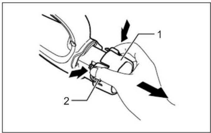
text_image
Diagram illustrating a mechanical or electrical component with labeled parts 1 and 2, showing directional arrows indicating movement or force.1
text_image
3 4 Transka2

text_image
53

natural_image
Illustration of hands using a tool to spread soil or vegetation, with no text or symbols present.4

natural_image
Line drawing of a person using a manual power shaver to cut a pile of material (no text or symbols)5
text_image
6 7 86

natural_image
Diagram of a person using a saw to cut through a slope with a numbered label (9) and no visible text or symbols.7
natural_image
Illustration of a hand using a power shaver to clean or spread debris (no text or symbols)8

natural_image
Illustration of a hand using a tool to clean or store material, with an upward arrow indicating flow (no text or symbols present)9
natural_image
Illustration of a hand using a tool to clean granular material, with an arrow indicating the process (no text or symbols present)10

text_image
10 11 12 1311 12
text_image
14[Non-Text]
text_image
1513 14
text_image
16[Non-Text]
text_image
17 18 20 1915 16
text_image
17[Non-Text]
text_image
2117 18

text_image
22 23
text_image
24 25
text_image
22 17 2319 20

text_image
22 26 27 2521 22

text_image
28 30 29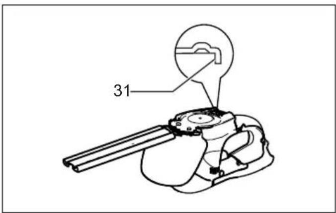
text_image
31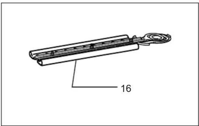
text_image
1623 24
text_image
2125 26

text_image
17 18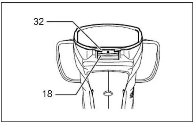
text_image
32 18
natural_image
Line drawing of a handheld device with two metal rods (no text or symbols)27 28
text_image
3329
text_image
34 35 36 3730
text_image
23 16 37
natural_image
Line drawing of a shoe being installed in a rack, showing the blade and base plate (no text or symbols)31 32
text_image
22 17 23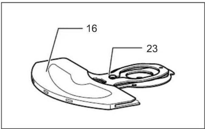
text_image
16 2333 34
text_image
24 25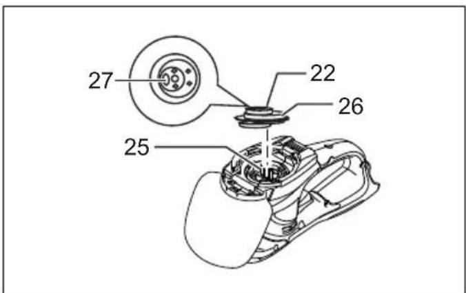
text_image
27 22 26 2535 36
text_image
30 29 28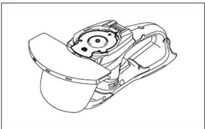
natural_image
Technical line drawing of a mechanical component with internal gears and housing (no text or symbols)37 38
text_image
17 1839 40

natural_image
Line drawing of a mechanical device with a rotating arrow indicating rotation (no text or symbols)
text_image
16
text_image
32 1841 42

text_image
17 23 22
text_image
17 23 22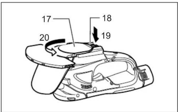
text_image
17 20 18 1943 44

text_image
3645 46
text_image
38 37
text_image
39 40 37
text_image
39 40 3747 48
natural_image
Illustration of a hand using a power tool to cut a surface with debris (no text or symbols)49 50

natural_image
Illustration of a hand using a power tool to cut a surface with grass (no text or symbols)
natural_image
Completely blank white image with no visible content, text, or symbols.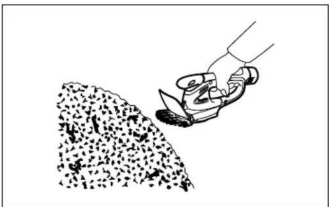
natural_image
Illustration of a hand using a tool to cut a pile of granular material (no text or symbols)51
ENGLISH (Original Instructions)
Explanation of general view
- Battery cartridge
- Button
- Lock-off button
- Switch trigger
- Indication lamp
- Trimming direction
- Tilt the blades
- Hedge surface to be trimmed
- String
- Clamping nuts
- Chip receiver
- Screws on the shear blades
- Blade cover to be always installed before installing the chip receiver
-
Brush
-
Machine oil
- Blade cover
- Undercover
- Locking lever
- Press
- Turn
- Screws
- Crank
- Shear blades
- Basic alignment line on the tool housing
- Pins
- Apply grease.
- Recessed part of crank
-
Oval holes that are overlapped
-
Hole in the base plate of shear blades
- Base plate
- Bent part of the base plate of shear blades
- Groove in the undercover
- Hook hole
- Grass shear blade
- Grass shear blade cover
- Storage case
- Base frame
- Groove
- Change lever
- Protrusion on base frame
SPECIFICATIONS
| Model UH200D | |
| Blade length 200 mm | |
| Strokes per minute (min ^-1 ) 1,250 | |
| Overall length 460 mm | |
| Net weight | 1.2 kg |
| Rated voltage | D.C. 10.8 V |
- Due to our continuing programme of research and development, the specifications herein are subject to change without notice.
- Specifications may differ from country to country.
• Weight according to EPTA-Procedure 01/2003
Symbols
END011-3
The following show the symbols used for the equipment. Be sure that you understand their meaning before use.

..... Take particular care and attention.


Read instruction manual.

Do not expose to rain.

Danger; be aware of thrown objects.

Keep bystanders away.

Cutting means continues to run after the motor is switched off.

Cd Ni-MH Li-ion
Only for EU countries
Do not dispose of electric equipment or battery pack together with household waste material! In observance of European Directive 2002/96/EC on waste electric and electronic equipment, 2006/66/EC on batteries and accumulators and waste
batteries and accumulators and their implementation in accordance with national laws, electric equipment and battery pack that have reached the end of their life must be collected separately and returned to an environmentally compatible recycling facility.
Intended use
ENE014-1
The tool is intended for trimming hedges.
General Power Tool Safety Warnings GEA010-1
WARNING Read all safety warnings and all instructions. Failure to follow the warnings and instructions may result in electric shock, fire and/or serious injury.
Save all warnings and instructions for future reference.
CORDLESS HEDGE TRIMMER SAFETY WARNINGS
GEB062-2
- Hold the power tool by insulated gripping surfaces only, because the cutter blade may contact hidden wiring. Cutter blades contacting a "live" wire may
make exposed metal parts of the power tool "live" and could give the operator an electric shock.
-
Keep all parts of the body away from the cutter blade. Do not remove cut material or hold material to be cut when blades are moving. Make sure the switch is off when clearing jammed material. A moment of inattention while operating the hedge trimmer may result in serious personal injury.
-
Carry the hedge trimmer by the handle with the cutter blade stopped. When transporting or storing the hedge trimmer always fit the cutting device cover. Proper handling of the hedge trimmer will reduce possible personal injury from the cutter blades.
-
Do not use the hedge trimmer in the rain or in wet or very damp conditions. The electric motor is not waterproof.
-
First-time users should have an experienced hedge trimmer user show them how to use the trimmer.
-
The hedge trimmer must not be used by children or young persons under 18 years of age. Young persons over 16 years of age may be exempted from this restriction if they are undergoing training under the supervision of an expert.
-
Use the hedge trimmer only if you are in good physical condition. If you are tired, your attention will be reduced. Be especially careful at the end of a working day. Perform all work calmly and carefully. The user is responsible for all damages to third parties.
-
Never use the trimmer when under the influence of alcohol, drugs or medication.
-
Check to make sure that the voltage and frequency of the power supply correspond to the specifications given on the identification plate. We recommend the use of a residual-current-operated circuit breaker (ground-fault circuit interrupter) with a tripping current of 30 mA or less, or an earth leakage current protector.
-
Work gloves of stout leather are part of the basic equipment of the hedge trimmer and must always be worn when working with it. Also wear sturdy shoes with anti-skid soles.
-
Before starting work check to make sure that the trimmer is in good and safe working order. Ensure guards are fitted properly. The hedge trimmer must not be used unless fully assembled.
-
Make sure you have a secure footing before starting operation.
-
Hold the tool firmly when using the tool.
-
Do not operate the tool at no-load unnecessarily.
-
Immediately switch off the motor and remove the battery cartridge if the cutter should come into contact with a fence or other hard object. Check the cutter for damage, and if damaged repair immediately.
-
Before checking the cutter, taking care of faults, or removing material caught in the cutter, always switch off the trimmer and remove the battery cartridge.
-
Switch off the trimmer and remove the battery cartridge before doing any maintenance work.
-
When moving the hedge trimmer to another location, including during work, always remove the battery cartridge. Never carry or transport the trimmer with the cutter running. Never grasp the cutter with your hands.
-
Clean the hedge trimmer and especially the cutter after use, and before putting the trimmer into storage for extended periods. Lightly oil the cutter and put on the cover. The cover supplied with the unit can be hung on the wall, providing a safe and practical way to store the hedge trimmer.
- Store the hedge trimmer with the cover on, in a dry room. Keep it out of reach of children. Never store the trimmer outdoors.
SAVE THESE INSTRUCTIONS.
WARNING:
DO NOT let comfort or familiarity with product (gained from repeated use) replace strict adherence to safety rules for the subject product. MISUSE or failure to follow the safety rules stated in this instruction manual may cause serious personal injury.
CORDLESS GRASS SHEAR SAFETY WARNINGS GEB070-2
WARNING! IMPORTANT READ CAREFULLY all safety warnings and all instructions BEFORE USE.
Failure to follow the warnings and instructions may result in electric shock, fire and/or serious injury.
Save all warnings and instructions for future reference.
General instructions
- To ensure correct operation, user has to read this instruction manual to make himself familiar with the handling of the equipment. Users insufficiently informed will risk danger to themselves as well as others due to improper handling.
- Never allow people unfamiliar with these instructions, people (including children) with reduced physical, sensory or mental capabilities, or lack of experience and knowledge to use the equipment. Local regulations can restrict the age of the operator.
- Use the equipment with the utmost care and attention.
- Operate the equipment only if you are in good physical condition. Perform all work calmly and carefully. Use common sense and keep in mind that the operator or user is responsible for accidents or hazards occurring to other people or their property.
- Never operate the machine while people, especially children, or pets are nearby.
- Never use the equipment after consumption of alcohol or drugs, or if feeling tired or ill.
- The motor is to be switched off immediately in case that the equipment shows any problem or abnormal sign.
- Switch off and remove the battery cartridge when resting and when leaving the equipment unattended, and place it in a safe location to prevent danger to others or damage to the equipment.
- Don't force the equipment. It will do the job better and with less likelihood of a risk of injury at the rate for which it was designed.
- Don't overreach. Keep proper footing and balance at all times.
Personal protective equipment
-
Dress Properly. The clothing worn should be functional and appropriate, i.e. it should be tight-fitting but not cause hindrance. Do not wear either jewelry or clothing which could become entangled. Wear protective hair covering to contain long hair.
-
Wear eye protection and stout shoes at all times while operating the machine.
Electrical and battery safety
- Avoid dangerous environment. Don't use the equipment in damp or wet locations or expose it to rain. Water entering an equipment will increase the risk of electric shock.
- Recharge only with the charger specified by the manufacturer. A charger that is suitable for one type of battery pack may create a risk of fire when used with another battery pack.
- Use power tools only with specifically designated battery packs. Use of any other battery packs may create a risk of injury and fire.
- When battery pack is not in use, keep it away from other metal objects, like paper clips, coins, keys, nails, screws or other small metal objects, that can make a connection from one terminal to another. Shorting the battery terminals together may cause burns or a fire.
- Under abusive conditions, liquid may be ejected from the battery; avoid contact. If contact accidentally occurs, flush with water. If liquid contacts eyes, additionally seek medical help. Liquid ejected from the battery may cause irritation or burns.
- Do not dispose of the battery(ies) in a fire. The cell may explode. Check with local codes for possible special disposal instructions.
- Do not open or mutilate the battery(ies). Released electrolyte is corrosive and may cause damage to the eyes or skin. It may be toxic if swallowed.
Starting up the equipment
- Make sure that there are no children or other people nearby, also pay attention to any animals in the working vicinity. Otherwise stop using the equipment.
- Before use always check that the equipment is safe for operation. Check the security of the cutting tool and the guard and the switch trigger/lever for easy and proper action. Check for clean and dry handles and test the function of the start/stop.
- Check damaged parts before further use of the equipment. A guard or other part that is damaged should be carefully checked to determine that it will operate properly and perform its intended function. Check for alignment of moving parts, binding of moving parts, breakage of parts, mounting, and any other condition that may affect its operation. A guard or other part that is damaged should be properly repaired or replaced by our authorized service center unless indicated elsewhere in this manual.
- Switch on the motor only when the hands and feet are away from the cutting tool.
- Before starting make sure that the cutting tool has no contact with any objects.
Method of operation
- Only use the equipment in good light and visibility. During the winter season beware of slippery or wet
areas, ice and snow (risk of slipping). Always ensure a safe footing.
-
Take care against injury to feet and hands from the cutting tool.
-
Never stand on a ladder and run the equipment.
-
Never climb up into trees to perform cutting operation with the equipment.
-
Never work on unstable surfaces.
-
Remove sand, stones, nails etc. found within the working range. Foreign particles may damage the cutting tool and can cause dangerous kick-backs.
-
Should the cutting tool hit stones or other hard objects, immediately switch off the motor and inspect the cutting tool.
-
Inspect the cutting tool at short regular intervals for damage (detection of hairline cracks by means of tapping-noise test).
-
Before commencing cutting, the cutting tool must have reached full working speed.
-
The cutting tool has to be equipped with the appropriate guard. Never run the equipment with damaged guards or without guards in place!
-
All protective installations and guards supplied with the equipment must be used during operation.
-
Always remove the battery cartridge from the equipment:
-
whenever leaving the equipment unattended;
- before clearing a blockage;
- before checking, cleaning or working on the equipment;
- after striking a foreign object;
-
whenever the equipment starts vibrating abnormally.
-
Always ensure that the ventilation openings are kept clear of debris.
Cutting Tools
- Employ only the correct cutting tool for the job in hand.
Maintenance instructions
- The condition of the equipment, in particular of the cutting tool of the protective devices must be checked before commencing work.
- Turn off the motor and remove the battery cartridge before carrying out maintenance, replacing cutting tools or cleaning the equipment or cutting tool.
- Check loose fasteners and damaged parts such as cracks in the cutting attachment.
- Follow instructions for lubricating and changing accessories.
- When not in use, store the equipment indoors in dry and high or locked-up place - out of the reach of children. Clean and maintain before storage.
- Use only the manufacturer's recommended replacement parts and accessories.
- Inspect and maintain the equipment regularly, especially before/after use. Have the equipment repaired only by our authorized service center.
- Keep handles dry, clean and free from oil and grease.
KEEP FOR FUTURE REFERENCE
WARNING:
DO NOT let comfort or familiarity with product (gained from repeated use) replace strict adherence to safety rules for the subject product. MISUSE or failure to
follow the safety rules stated in this instruction manual may cause serious personal injury.
IMPORTANT SAFETY INSTRUCTIONS
ENC007-4
FOR BATTERY CARTRIDGE
- Before using battery cartridge, read all instructions and cautionary markings on (1) battery charger, (2) battery, and (3) product using battery.
- Do not disassemble battery cartridge.
- If operating time has become excessively shorter, stop operating immediately. It may result in a risk of overheating, possible burns and even an explosion.
- If electrolyte gets into your eyes, rinse them out with clear water and seek medical attention right away. It may result in loss of your eyesight.
- Do not short the battery cartridge:
(1) Do not touch the terminals with any conductive material.
(2) Avoid storing battery cartridge in a container with other metal objects such as nails, coins, etc.
(3) Do not expose battery cartridge to water or rain.
A battery short can cause a large current flow, overheating, possible burns and even a breakdown.
- Do not store the tool and battery cartridge in locations where the temperature may reach or exceed 50^ C ( 122^ F).
- Do not incinerate the battery cartridge even if it is severely damaged or is completely worn out. The battery cartridge can explode in a fire.
- Be careful not to drop or strike battery.
- Do not use dropped or struck battery.
SAVE THESE INSTRUCTIONS.
Tips for maintaining maximum battery life
- Charge the battery cartridge before completely discharged. Always stop tool operation and charge the battery cartridge when you notice less tool power.
-
Never recharge a fully charged battery cartridge. Overcharging shortens the battery service life.
-
Charge the battery cartridge with room temperature at 10^ C - 40^ C ( 50^ F - 104^ F). Let a hot battery cartridge cool down before charging it.
FUNCTIONAL DESCRIPTION
CAUTION:
- Always be sure that the tool is switched off and the battery cartridge is removed before adjusting or checking function on the tool.
Installing or removing battery cartridge (Fig. 1)
- Always switch off the tool before insertion or removal of the battery cartridge.
- To remove the battery cartridge, withdraw it from the tool while pressing the buttons on both sides of the cartridge.
- To insert the battery cartridge, hold it so that the battery cartridge front shape fits to that of the battery installment opening and slip it into place. Always insert it all the way until it locks in place with a little click. If not, it may accidentally fall out of the tool, causing injury to you or someone around you.
- Do not use force when inserting the battery cartridge. If the cartridge does not slide in easily, it is not being inserted correctly.
Switch action (Fig. 2)
CAUTION:
- Before inserting the battery cartridge into the tool, always check to see that the switch trigger actuates properly and returns to the "OFF" position when released.
To prevent the switch trigger from being accidentally pulled, a lock-off button is provided.
To start the tool, depress the lock-off button and pull the switch trigger. Release the switch trigger to stop. The lock-off button can be pressed from either right or left side.
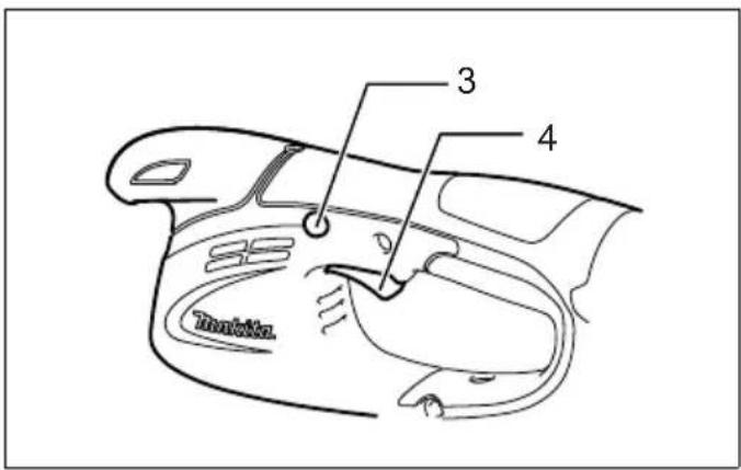
Indication lamp (Fig. 3)
Running the tool allows the indication lamp to show the battery cartridge capacity status.
When the tool is also overloaded and has stopped during operation, the lamp lights up in red.
Refer to the following table for the status and action to be taken for the indication lamp.
| Indication lamp Status Action to be taken | ||
| The lamp blinks in red. This indicates the appropriate time to replace the battery cartridge when the battery power becomes low. | Recharge the battery cartridge as soon as possible. | |
| The lamp lights up in red. (Note 1) This function works when the battery power is almost used up. At this time, tool stops immediately. | Recharge the battery cartridge. | |
| The lamp lights up in red. (Note 1) Auto stop due to overload. Turn off the tool. | ||
Note 1: The time at which the indication lamp lights up varies by the temperature around the work area and the battery cartridge conditions.
OPERATION
Refer to the Safety Warnings before operation.
CAUTION:
- Be careful not to accidentally contact a metal fence or other hard objects while trimming. The blade will break and may cause serious injury.
- Also, be careful for the shear blade not to contact the ground.
• Overreaching with a hedge trimmer, particularly from a ladder, is extremely dangerous. Do not work from anything wobbly or infirm. (Fig. 4)
Do not attempt to cut branches thicker than 10 mm diameter with this trimmer. These should first be cut with shears down to the hedge trimming level.
CAUTION:
- Do not cut off dead trees or similar hard objects. Failure to do so may damage the tool.
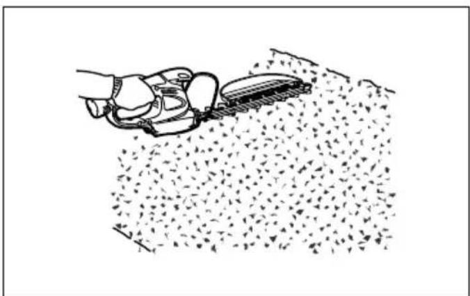
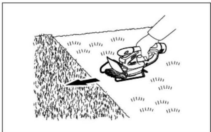
- Do not trim the grass or weeds while using hedge shear blade. The shear blade may entangle the grass or weeds. (Fig. 5)
Hold the trimmer with one hand, depress the lock-off button and pull the switch trigger and then move it in front of your body. (Fig. 6)
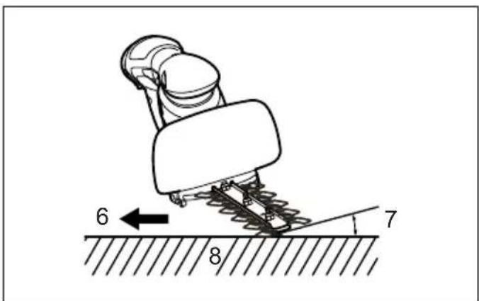
As a basic operation, tilt the blades towards the trimming direction and move it calmly and slowly at the speed rate of 3 - 4 seconds per meter. (Fig. 7)
To cut a hedge top evenly, it helps to tie a string at the desired hedge height and to trim along it, using it as a reference line. (Fig. 8)
Attaching the chip receiver (accessory) on the tool when trimming the hedge straight can avoid cut off leaves' being thrown away. (Fig. 9)
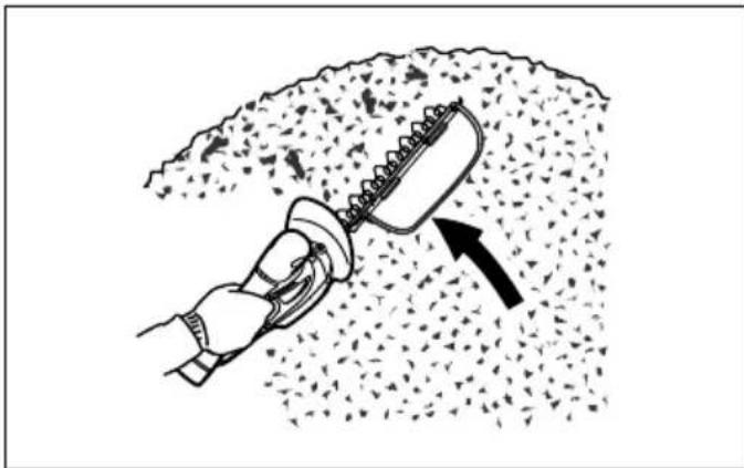
To cut a hedge side evenly, it helps to cut from the bottom upwards. (Fig. 10)
Trim boxwood or rhododendron from the base toward the top for a nice appearance and good job.
Installing or removing chip receiver (accessory)
CAUTION:
- Always be sure that the tool is switched off and the battery cartridge is removed before installing or removing chip receiver.
NOTE:
- When replacing the chip receiver, always wear gloves so that hands and face does not directly contact the blade. Failure to do so may cause personal injury.
- When replacing the chip receiver, always be careful not to contact the shear blades.
- The chip receiver receives cut-off leaves and alleviates collecting thrown-away leaves. This can be installed on either side of the tool. (Fig. 11)
Place the chip receiver on the shear blades so that its slits overlap with the screws on the shear blades and secure it using two clamping nuts.
To remove the chip receiver, loosen and remove the two clamping nuts and then take it out.
MAINTENANCE
CAUTION:
- Always be sure that the tool is switched off and the battery cartridge is removed before attempting to perform inspection or maintenance.
Cleaning the tool
Clean out the tool by wiping off dust with a dry or soap-dipped rag.
CAUTION:
- Never use gasoline, benzine, thinner, alcohol or the like. Discoloration, deformation or cracks may result.
Shear blade maintenance (Fig. 12)
Smear the blade before and once per hour during operation using machine oil or similars. (Fig. 13) After operation, remove dust from both sides of the blade with wired brush, wipe off it with a rag and then apply enough low-viscosity oil, such as machine oil etc. and spray-type lubricating oil.
CAUTION:
- Do not wash the blades in water. Failure to do so may cause rust or damage on the tool.
Removing or installing hedge shear blades
CAUTION:
- Before removing or installing shear blades, always be sure that the tool is switched off and the battery cartridge is removed.
- When replacing the shear blades, always wear gloves without removing blade cover so that hands and face do not directly contact the blade. Failure to do so may cause personal injury.
NOTE:
- Do not wipe off grease from the gear and crank. Failure to do so may cause damage to the tool.
- For specific way of removing and installing shear blades refer to the reverse of a package for accessory shear blades.
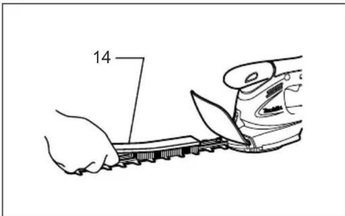
Removing the hedge shear blades (Fig. 14)
CAUTION:
• Install the blade cover before removing or installing the shear blades.
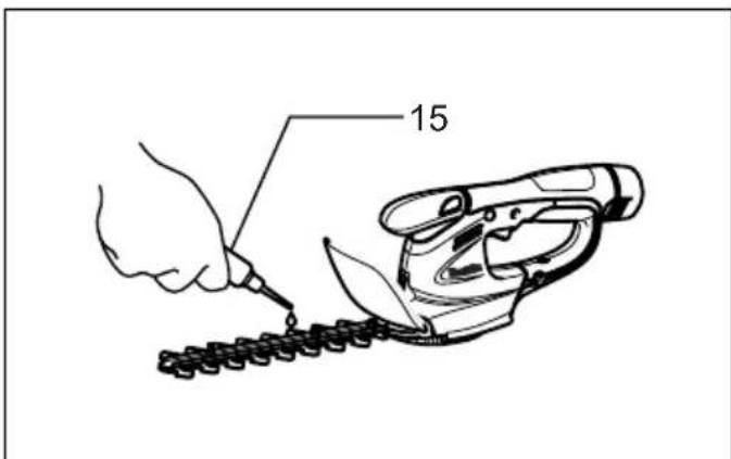
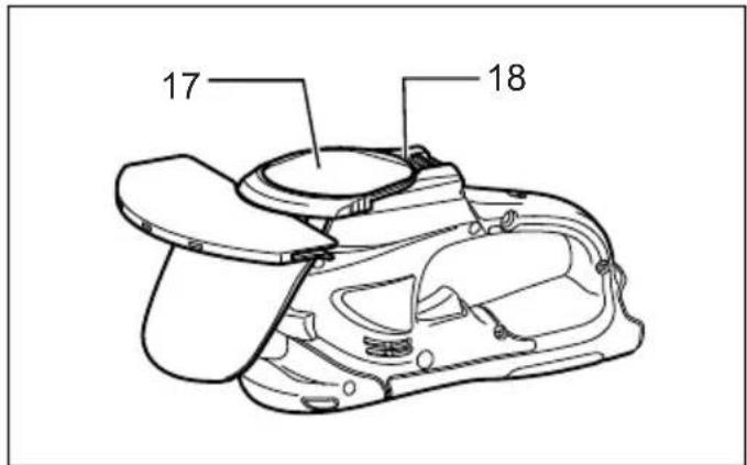
Reverse the tool. (Fig. 15)
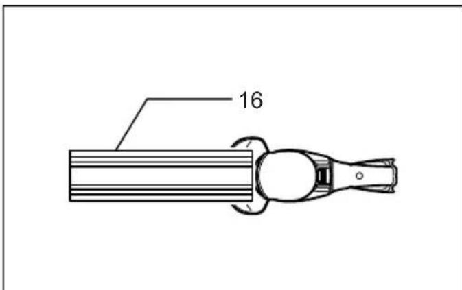
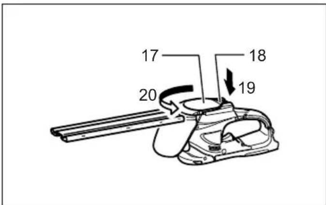
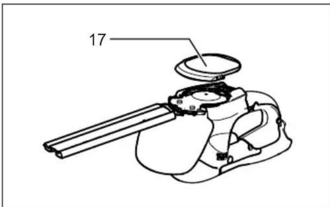
To remove the shear blades, press the locking lever and with the locking lever pressed turn the undercover counterclockwise until the symbol on the undercover is aligned with the symbol on the locking lever. (Fig. 16) Take out the undercover from the tool. (Fig. 17) Loosen two screws with a coin and similars and remove the shear blades.
NOTE:
- Do not remove the screws. Without removing the screws loosened, shear blades can be removed. (Fig. 18)
Remove the crank from the shear blades.
NOTE:
• The crank may remain in the tool.
Installing the hedge shear blades (Fig. 19)
Prepare the crank, the undercover and new shear blades. (Fig. 20)
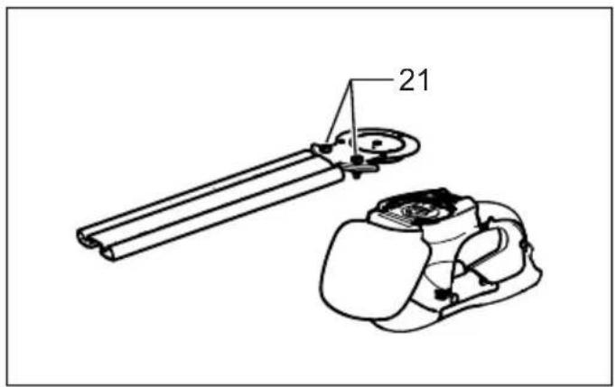
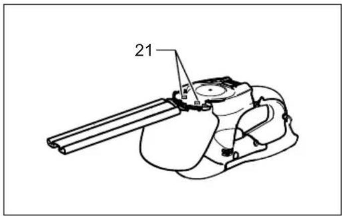
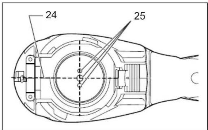
Adjust the three detent pin position so that these three pins are aligned with the basic alignment line on the tool housing. (Fig. 21)
Fit the crank with its recessed part facing downward onto the detent pins. At this time, apply a small amount of grease to the periphery of the crank using grease that the shear blades as optional accessory are provided with or that remains inside gear housing. (Fig. 22)
Overlap the oval hole in the upper blade with that in the lower one. Move the shear blades so that the hole in the base plate of shear blades are positioned in the center of these overlapped oval holes. (Fig. 23)
Take out the blade cover from the old shear blades and fit it onto the new ones for easy handling during the replacement of blades. (Fig. 24)
Turn the shear blades upside down and install it so that pin on the tool fit in the hole in the shear blades. Fit the bent part of the base plate of the shear blades to the groove in the tool housing. Then make sure that the base plate of the shear blades is set in place. (Fig. 25)
Tighten two screws with a coin or similar firmly. (Fig. 26)
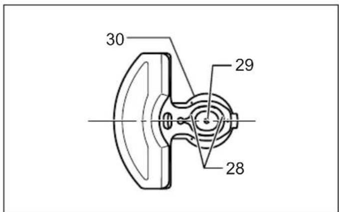
Place the undercover so that the symbol on the undercover is aligned with the symbol on the locking lever. (Fig. 27)
Press the undercover down and with the undercover pressed down turn the undercover clockwise until the symbol ☐ on the label is aligned with the symbol ☐ on the locking lever (the undercover is completely locked).
(Fig. 28)
At this time, make sure that the locking lever fits in the groove in the undercover.

CAUTION:
- Never use the tool without installing the undercover on it.
Remove the blade cover and then turn on the tool to check it for proper movement.
NOTE:
- When the shear blades does not operate properly, there is a poor fit between the blades and crank. Redo from the beginning.
Storage (Fig. 29)
The hook hole in the tool bottom is convenient for hanging the tool from a nail or screw on the wall.
Put the blade cover on the shear blades so that the blades are not exposed. Store the tool out of the reach of children carefully.
Store the tool in the place not exposed to water and rain. To maintain product SAFETY and RELIABILITY, repairs, carbon brush inspection and replacement, any other maintenance or adjustment should be performed by Makita Authorized Service Centers, always using Makita replacement parts.
ACCESSORIES

CAUTION:
• These accessories or attachments are recommended for use with your Makita tool specified in this manual. The use of any other accessories or attachments might
present a risk of injury to persons. Only use accessory or attachment for its stated purpose.
If you need any assistance for more details regarding these accessories, ask your local Makita Service Center.
• Hedge shear blade cover
• Hedge shear blade assembly
- Chip receiver for hedge trimming
- Makita genuine battery and charger
For cordless grass shear use (Fig. 30)
This tool can be used as a grass shear by using the grass shear blade (optional accessory) and 2-way change set.
To use this tool as a grass shear, replacing the hedge shear blades with the grass shear blades is required.
For removing the hedge trimmer blades, refer to the aforementioned section titled "Removing the hedge shear blades".
For installing the grass shear blade, refer to the section below titled "Installing or removing grass shear blades".
- Grass shear blade assembly (for Grass Shear)
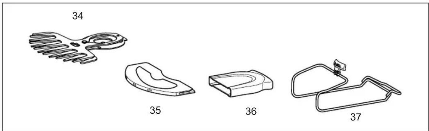
- 2-way change set consisting of the following three accessories
- Grass shear blade cover (for Grass Shear)
- Storage case (for blade bottom section)
- Base frame (for Grass Shear)
- Long handle attachment (for Grass Shear)
ASSEMBLY
CAUTION:
- Always be sure that the tool is switched off and the battery cartridge is removed before carrying out any work on the tool.
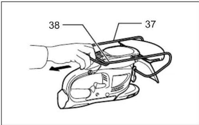
Installing or removing blade cover (Fig. 31 & 32)
CAUTION:
- Be careful not to contact the shear blade when installing or removing the blade cover. Contacting the shear blade may cause personal injuries.
Slide the blade cover from the tool's side until the shear blade completely hides itself and then push in it lightly towards the tool from the front.
To remove the blade cover, take the above installation procedure in reverse.
Installing or removing grass shear blades
CAUTION:
• Always be sure that the tool is switched off and the battery cartridge is removed before installing or removing shear blades. Failure to switch off and remove the battery cartridge from the tool may result in serious injury from accidental start-up.
- When replacing the shear blade, always wear gloves without removing blade cover so that hands and face do not directly contact the blade. Failure to do so may cause personal injury.
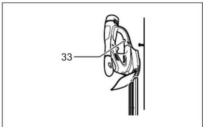
NOTE:
- Do not wipe off grease from the gear and crank. Failure to do so may cause damage to the tool.
- For specific way of removing and installing shear blades refer to the reverse of a package for accessory shear blades. (Fig. 33)
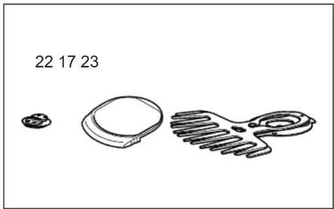
To install the grass shear blade, prepare the crank, undercover and new grass shear blade. (Fig. 34)
Take out the blade cover from the old shear blades and fit it onto the new ones for easy handling during the replacement of blades. (Fig. 35)
Adjust the three detent pin position so that these pins are lined up at right angle in relation to the basic alignment line on the tool housing. (Fig. 36)
Fit the crank with its recessed part facing upwards onto the detent pins. At this time, apply a small amount of grease to the periphery of the crank using grease that the shear blades as optional accessory are provided with or that remains inside gear housing. (Fig. 37)
Overlap the oval hole in the upper blade with that in the lower one. Move the shear blades so that the hole in the base plate of shear blades are positioned in the center of these overlapped oval holes. (Fig. 38)
Turn the shear blades upside down and install it so that the detent pins on the tool fit in the hole in the shear blades. Make sure that the shear blades are set in place securely as far as they reach the base plate. (Fig. 39)
Place the undercover so that the symbol on the undercover is aligned with the symbol on the locking lever. (Fig. 40)
Press the undercover down and with the undercover pressed down turn the undercover clockwise until the symbol on the label is aligned with the symbol on the locking lever (the undercover is completely locked).
(Fig. 41)
At this time, make sure that the locking lever fits in the groove in the undercover.
Remove the blade cover and then turn on the tool to check it for proper movement.
NOTE:
- When the shear blades does not operate properly, there is a poor fit between the blades and crank. Redo from the beginning. (Fig. 42)
Remove the base frame and place the tool upside down.

CAUTION:
- Before placing the tool upside down, be sure to remove the base frame. (Fig. 43)
To remove the shear blade, press the locking lever and with the locking lever pressed turn the undercover counterclockwise until the symbol on the undercover is aligned with the symbol on the locking lever. (Fig. 44)
Take out the undercover, shear blade and crank in order from the tool. (Fig. 45)
NOTE:
- In the 2-way usage, the removed hedge shear blade need to be sheared in the blade storage case and then stored for future use.
Installing or removing base frame

CAUTION:
- Before installing or removing base frame, be sure to install the blade cover.
- When installing or removing base frame, take care that your fingers are not be pinched between the tool and base frame. (Fig. 46)
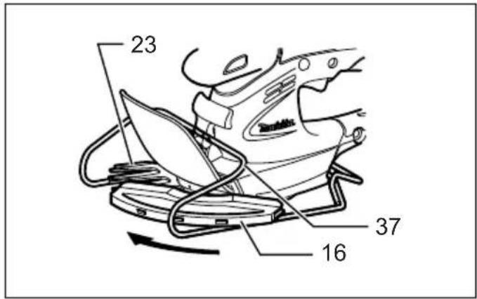
To remove the base frame, upset the tool and take it out of the groove grabbing its bottom. (Fig. 47)
To install the base frame, fit the protrusion of base frame near the change lever into the hole for the sheared grass height setting. With the base frame so fitted, pull the lower part of base frame and fit the other part of the base frame in the groove in the tool.
Adjusting the shearing height (Fig. 48)
Changing the position of holding the change lever allows three-stepped setting for sheared grass height (10 mm, 15 mm, 25 mm).
To change setting, tilt the change lever for the base frame position and with the change lever tilted move it up or down along the tool surface until the protrusion on base frame fits in one of the holes in the tool and release it.
OPERATION

WARNING:
- Keep hands away from blades.

CAUTION:
- Smear the blade before and once per hour during operation using machine oil or similar.
- Avoid operating the tool under the scorching sunlight as much as practicable. When operating the tool, be careful of your physical conditions. (Fig. 49)
Turn the tool on after adjusting the shearing height and hold it so that the foot of the tool rest on the ground. Then gently move the tool forward into the area to be cut.
(Fig. 50)
When trimming around curb, fence or trees, move the tool along them. Be careful for the blade not to contact them.
(Fig. 51)
When trimming sprouts or foliage of a small tree, remove the base frame from the tool and cut little by little.
Shear big branches to your desired height beforehand using branch scissors before using this tool.

CAUTION:
- When trimming twigs and foliage, do not attempt to trim too much at a time. Proceed gently. Also do not attempt to cut thick branches.
- Do not let the shear blades contact the grounds during operation. The blades will be dulled, causing poor performance.
- Do not trim wet grass or foliage of small trees.
Noise
ENG104-2
The typical A-weighted noise level determined according to EN60745:
Sound pressure level ( L_pA ): 73.7 dB (A)
Uncertainty (K): 2.5 dB (A)
The noise level under working may exceed 80 dB (A).
Wear ear protection.
Vibration
ENG244-1
The vibration emission value determined according to EN60745:
Vibration emission ( a_h ): 2.5 m/s ^2 or less
Uncertainty (K): 1.5 m/s ^4
ENG901-1
- The declared vibration emission value has been measured in accordance with the standard test method and may be used for comparing one tool with another.
- The declared vibration emission value may also be used in a preliminary assessment of exposure.

WARNING:
- The vibration emission during actual use of the power tool can differ from the declared emission value depending on the ways in which the tool is used.
- Be sure to identify safety measures to protect the operator that are based on an estimation of exposure in the actual conditions of use (taking account of all parts of the operating cycle such as the times when the tool is switched off and when it is running idle in addition to the trigger time).
For European countries only
ENH021-5
EC Declaration of Conformity
We Makita Corporation as the responsible manufacturer declare that the following Makita machine(s):
Designation of Machine:
Cordless Hedge Trimmer
Model No./ Type: UH200D
Specifications: see "SPECIFICATIONS" table.
are of series production and
Conforms to the following European Directives:
2000/14/EC, 2006/42/EC
And are manufactured in accordance with the following
standards or standardised documents:
EN60745
The technical documentation is kept by our authorised representative in Europe who is:
Makita International Europe Ltd.,
Michigan, Drive, Tongwell,
Milton Keynes, MK15 8JD, England
The conformity assessment procedure required by
Directive 2000/14/EC was in Accordance with annex V.
Measured Sound Power Level: 81.8 dB
Guaranteed Sound Power Level: 84 dB
27th August 2009

Tomoyasu Kato
Director
Makita Corporation
3-11-8, Sumiyoshi-cho,
Anjo, Aichi, JAPAN
Michigan, Drive, Tongwell,
Milton Keynes, MK15 8JD, Angleterre
3-11-8, Sumiyoshi-cho,
Anjo, Aichi, JAPAN
Makita International Europe Ltd., Michigan, Drive, Tongwell, Milton Keynes, MK15 8JD, Engla
Makita International Europe, Ltd., Michigan, Drive, Tongwell,
Milton Keynes, MK15 8JD, Inghilterra
3-11-8, Sumiyoshi-cho,
Anjo, Aichi, JAPAN
WAARSCHUWING Lees alle
BEWAAR VOOR LATERE NASLAG
⚠ WAARSCHUWING:
Makita International Europe Ltd., Michigan Drive, Tongwell,
Milton Keynes, MK15 8JD, Engeland
3-11-8, Sumiyoshi-cho,
Anjo, Aichi, JAPAN
Tomoyasu Kato Director
Makita Corporation
3-11-8, Sumiyoshi-cho, Anjo, Aichi, JAPAN
2000/14/EC, 2006/42/EC
Michigan, Drive, Tongwell,
Milton Keynes, MK15 8JD, Inglaterra
Tomoyasu Kato Director
Makita Corporation
3-11-8, Sumiyoshi-cho,
Anjo, Aichi, JAPAN
2000/14/EF, 2006/42/EF
Og er produceret i overensstemmelse med følgende
standarder eller standardiserede dokumenter: EN60745
Michigan, Drive, Tongwell,
Milton Keynes, MK15 8JD, England
3-11-8, Sumiyoshi-cho,
Anjo, Aichi, JAPAN
2000/14/EK, 2006/42/EK
Makita International Europe Ltd., Michigan, Drive, Tongwell,
Milton Keynes, MK15 8JD, England