
GVW865 - Dishwasher Pelgrim - Free user manual and instructions
Find the device manual for free GVW865 Pelgrim in PDF.

| Product type | Built-in dishwasher |
| Brand | Pelgrim |
| Model | GVW865 |
| Capacity | 12 place settings |
| Dimensions (H x W x D) | 820-870 x 596 x 550 mm |
| Door panel height | 650-720 mm (width 598 mm) |
| Voltage | 230 V |
| Frequency | 50 Hz |
| Number of programs | 12 |
| Available programs | Pre-rinse, Delicate, Glassware, Quick, Normal, Daily, Bio, Eco Bio, Heavy, Bio-plus, Intensive, Rinse |
| Options | Eco, Half load, No drying, Delayed start (1-9h) |
| Basket types | Height-adjustable upper basket, lower basket, cutlery basket |
| Filtration system | Multi-stage filters (microfilter, filter, coarse filter) |
| Spray arms | Removable upper and lower |
| Water softener | Adjustable to 5 positions |
| Safety | Aquastop system, automatic stop at end of program |
| Audible signal | Adjustable (on/off) |
| Water pressure | Adjustable (normal/low) |
| Reservoirs | Regenerating salt (capacity 1.7 kg), rinse aid (140 cc), detergent (25 g) |
| Weight (approx) | 45 kg |
Frequently Asked Questions - GVW865 Pelgrim
User questions about GVW865 Pelgrim
0 question about this device. Answer the ones you know or ask your own.
Ask a new question about this device
Download the instructions for your Dishwasher in PDF format for free! Find your manual GVW865 - Pelgrim and take your electronic device back in hand. On this page are published all the documents necessary for the use of your device. GVW865 by Pelgrim.
USER MANUAL GVW865 Pelgrim
Manual Dishwasher integrated
natural_image
Line drawing of a kitchen appliance with front panel and side panel (no text or symbols)GVW855
GVW865
Nederlands 1 - 21
English 22 - 43
Français 44 - 65
Deutsch 66 - 86
|Pelgrim|
fig. 1
B – programmakeuze-toets
natural_image
Illustration of a hand pouring liquid into a funnel inside a vehicle cabin (no text or symbols visible)fig. 3
Waterontharder
natural_image
Illustration of a hand using a tool to adjust or install a mechanical component, with no visible text or symbols.fig. 4a
| waterhardheid instellingen | ||
| Duitse Fransegraden graden | ||
| 0 - 4 °dH 0 - | 7 °dF stand 1 | (geen zout) |
| 5 - 15 °dH 8 | - 25 °dF stand 1 | |
| 16 - 23 °dH 26 | - 40 °dF stand 2 | |
| 24 - 31 °dH 41 | - 60 °dF stand 3 | |
| 32 - 47 °dH 61 | - 80 °dF stand 4 | |
| 48 - 58 °dF | 81 - 100 °dF | stand 5 |

fig. 4b
| waterhardheid instellingen | |
| Duitse Fransegraden graden | |
| 0 - 4 °dH 0 | 7 °dF stand 1(geen zout) |
| 5 - 9 °dH 0 | 18 °dF stand 1 |
| 10 - 22 °dH 16 | - 37 °dF stand 2 |
| 23 - 29 °dH 38 | - 50 °dF stand 3 |
| 30 - 35 °dH 51 | - 60 °dF stand 4 |
| 36 - 41 °dH 61 | - 70 °dF stand 5 |
natural_image
Line drawing of a hand holding a small object next to a mechanical structure with rollers (no text or symbols)fig. 7

natural_image
Technical line drawing of a mechanical assembly with pulleys and a bracket (no text or symbols)fig. 8
natural_image
Technical line drawing of a mechanical assembly with a hand operating it, showing internal components and an upward arrow (no text or symbols)fig. 9

natural_image
Illustration of a hand operating a mechanical device with a downward arrow indicating rotation (no text or symbols present)fig. 10
natural_image
Cross-sectional diagram of a cylindrical mechanical component with internal gear-like structure (no text or symbols)fig. 11
natural_image
Isometric technical diagram of a mechanical assembly with no visible text or symbolsfig. 12
natural_image
Diagram of a basket with two compartments and upward arrows indicating movement (no text or symbols)fig. 13
Geen water in de machine
oorzaak remedie
natural_image
Technical line drawing of a mechanical assembly with a bracket and a tool labeled 'R' (no text or symbols present)fig. 14
fig. 16a

fig 16b

natural_image
Technical diagram showing a mechanical assembly with an arrow indicating direction, alongside a circular component with a cross symbol (no text or labels)fig. 15

fig. 16c

fig. 16d
natural_image
Isometric line drawing of a rectangular object with a small protrusion and a vertical line, labeled 'fig. 17' (no text or symbols on the object itself)natural_image
Technical line drawing of a door panel assembly with mounting bracket (no text or symbols)fig. 18a
natural_image
Technical line drawing of a mechanical assembly with an inset showing a detail (no text or symbols)fig. 18b
natural_image
Technical line drawing of a mechanical assembly with a tool and circular component (no text or symbols)fig. 19
natural_image
Technical line drawing of a structural assembly with beams and supports (no text or symbols)fig. 20
Let op:
Appliance information A and B
(fig. 1)
A – upper basket
B – upper spray arm
C - lower basket
D - lower spray arm
E – water-softening salt container
F-filter
G - containers for detergent and rinse-aid
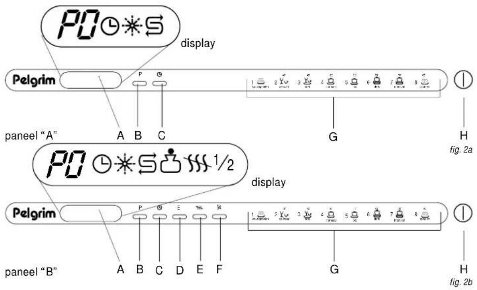
Control panel (fig. 2a and 2b)
A – display
B – programme selection button
C – adjustable starting-time button – up to 9 hours (if applicable)
D - ECO button (if applicable)
E - drying button (if applicable)
F-half-load button (if applicable)
G – programme overview
H - main switch
Personal preferences
Audible signal
When you press a button you hear an audible signal. You can switch this signal off.
- Press the and buttons at the same time. Press the button until the symbol appears on the display. Use the button to switch the audible signal off (appears on the display) or on (appears on the display).
Water pressure
You can adjust the water pressure in the dishwasher to the pressure of the supply water.
- Press the and buttons at the same time. Press the button until the symbol appears on the display. Use the button to switch button to switch from normal (appears on the display) to low pressure (appears on the display).
Display codes
The following information may appear on the display:
1 – programme selected / time delay to start of programme / error code.
2 - delayed start time indicator. The symbol lights up if the start time has been delayed.
3 - rinse aid indicator. The symbol lights up if the rinse aid reservoir needs refilling.
4 - salt indicator. The symbol lights up if the salt reservoir needs refilling.salt indicator. The symbol lights up if the salt reservoir needs refilling.
5 - economy programme indicator. The symbol lights up if the economy programme has been selected.
Introduction
When you have read these instructions for use, you will quickly be aware of all the facilities the appliance can offer you. You can read about safety and how you should look after the appliance. In addition you will find environmental tips and instructions that can help to save energy.
Keep the instructions for use and the installation instructions. Any later user of this appliance could benefit from them.
Table of contents GB
■ Appliance information ..... 22
■ Introduction ...... 23
■ Safety 24 - 26
Before using the appliance ..... 24
Things to watch out for 25
Controls 27-28
Programme overview 27
Explanation of programme ..... 28
Use 29 - 34
Salt, rinse-aid and detergent ..... 29
Baskets 32
The first cycle 34
Extra programmes 34
■ Faults 35 - 36
Error codes 35
Trouble shooting 36
■ Cleaning 37 - 38
■ Installation 38 - 39
■ Mounting 39 - 41
■ Disposal of packaging and appliance .. 42
Before using the appliance
The appliance should only be connected by a qualified fitter (see electrical connection).
- Do not use the appliance if it has been damaged during transport. Contact your dealer.
■ This appliance is designed for household use only.
- Do not use the appliance if you have wet hands or if you are standing on bare feet.
- Keep packaging material, such as plastic bags, polystyrene and wood out of the reach of children.
- Keep detergents out of the reach of children. Keep children away from the appliance: it is not a toy.
■ Disconnect the appliance before starting to clean or repair it, preferably, by taking the plug out of the socket or by turning off the mains switch.
■ Do not use an extension cable.
■ Never clean electrical appliances (mixer, food processor etc.) in the dishwasher.
- Do not place any plastic utensils on the heating element. Plastic objects could melt.
■ Never use detergents containing phosphates or bleaches. - Avoid limescale by regularly refilling the regenerative salts. Use only the special salt intended for dishwashers (do not use iodized salt).
■ Never fill the rinse-aid-, detergent- or salt compartments with solvents such as benzine, turpentine or alcohol. This could cause an explosion.
■ Regularly check that the sprinklers and the filter element are clean.
■ Never use the dishwasher without the filters. - Do not stand or sit on the open door of your dishwasher. The appliance may topple over.
- Do not touch the heating element, either during or immediately after the end of the washing programme.
Things to watch out for
Before you place kitchenware in the machine
■ First remove food remains. You thereby avoid blockages.
■ First soak any pots/pans that are very dirty.
Environmental tips
■ Save your dirty kitchenware and only use your dishwasher when one (in the case of the half-load option) or both baskets have been filled.
■ Always select the most suitable programme, depending on how dirty your dishes are.
■ Make no use, or as little use as possible, of the pre-rinse programme.
- If possible, connect the machine to a hot-water plant with a maximum temperature of 60°C.
China ware
Not suitable:
All sorts of china ware with an onglaze decoration or edge which you can see and feel. Also consider the shape of the china ware. Bell-shaped cups break more easily than straight-sided cups. Under no circumstances should you put porous earthenware in your dishwasher.
Suitable:
China ware fired at a temperature of 700/800 °C.
Do not use too much rinse-aid in this case, to
avoid any damage. Only white or single-colour china ware which is fired at a temperature of 1200/1300 °C is completely dishwasher proof.
Glass
Not suitable:
Crystal or hand-blown glassware; glass on which the decoration has been burnt in; glassware with a gold edging.
Suitable:
All other glass.
Cutlery
Not suitable:
Cutlery with a wooden, earthenware or china-ware handle. There is a big risk of cracks. In fact, there is a big risk of cracks for all wooden objects washed in a dishwasher. Cutlery made of chromium steel is not very suitable for washing in the dishwasher. In the case of this cutlery, there is a risk of corrosion (rust).
Suitable:
Cutlery made of chromium nickel steel 18/10. This high-quality cutlery is rustproof and acid-resistant. However, the blade of a knife may be made of a different material. Watch out for this. Silver or silver-plated cutlery is also dishwasher proof. But in this case the rinse-aid used must not contain any citric acid, since this damages the silver. Moreover, regular washing in the dishwasher may result in the silver becoming scratched.
Attention:
You will get longer-lasting pleasure from your cutlery and dishwasher if you follow these tips:
■ After using the cutlery – especially knives – rinse it under the tap. You hereby prevent it being damaged by food remains containing salt and acid.
■ Always place knives, forks and spoons in the dishwasher with the handle downwards.
- Do not put chromium nickel steel cutlery and chromium steel cutlery together in the dishwasher. Otherwise, you run the risk of rust contamination.
■ Take the cutlery out of the dishwasher immediately after the rinsing programme and dry it with a cloth. Never leave damp cutlery in the dishwasher.
■ Never put silver and stainless steel cutlery in one basket together.
■ Silver cutlery should never be allowed to come into contact with aluminium, since this can damage the silver.
■ Plastic pan handles can become dull.
Furthermore...
■ Plastic objects must be heat-resistant.
■ Aluminium pans, kitchenware and various types of glassware may become discoloured after being washed several times in the dishwasher. Certain sorts of decoration may lose their colour.
- Watch out for the indication "Suitable for the dishwasher" in the case of glazed pottery.
- When you buy new tableware, look for forms which are suitable for the dishwasher: such as straight, smooth sides, large openings, cavities which are not too deep, dishwasher-proof decoration, cutlery and earthenware.
Controls


| Programme overview | ||||||||||
| programme sel. | E- suitable switch | button | for gent prewash wash | amount of deter-rinse rinse | program sequence drying | drying | cold hot | no- | ||
| Pre-rinse 1 – | dishes and pans | – | cold | – | – | – | – | – | ||
| Delicate | 2 – | lightly soiled dishes | 25 | – | 45 °C | 1 | 65 °C | yes | $$ | |
| Glassware | 2 E | lightly soiled dishes, such as glasses and cups | 25 | – | 45 °C | 1 | 55 °C | yes | $ | |
| Fast | 3 – | medium and lightly-soiled dishes not caked with food remnants | 25 | – | 45 °C | 2 | – | – | – | |
| Normal | 4 – | dishes with average soiling and caked with food remnants | 30 | cold | 65 °C | 1 | 65 °C | yes | $ | |
| Daily | 4 E | lightly-soiled dishes not caked with food remnants | 30 | – | 65 °C | 1 | 65 °C | yes | $ | |
| Bio | 5 – | lightly-soiled dishes caked with food remnants | 30 | cold | 55 °C | 1 | 65 °C | yes | $ | |
| Eco Bio (*) | 5 E | lightly-soiled dishes caked with food remnants | 30 | – | 55 °C | 1 | 65 °C | yes | $ | |
| Strong | 6 – | heavily-soiled dishes caked with food remnants and pans with average soiling | 30 | cold | 68 °C | 2 | 68 °C | yes | $ | |
| Bio-plus (without pre-wash) | 6 E | dishes with average soiling and caked with food remnants | 30 | – | 68 °C | 2 | 68 °C | yes | $ | |
| Intensive 7 – | heavily-soiled dishes caked with food remnants and pans with average soiling | 30 | – | 70 °C | 2 | 70 °C | yes | $ | ||
| Rinse (**) | 8 – | dishes which need *freshening up* | – | – | – | 1 | 65 °C | yes | $$ | |
Only select pre-rinse with partial loads.
The half load program (1/2) is available for all programs, except "Pre rinse".
(*) Reference cycle according to EN 50242
(**) Before starting programme 8, you must make sure that the detergent reservoir lid is open.
You can select "no drying" (✗) where indicated. This shortens the programme and saves energy.
| Explanation of programmes | ||
| Symbol Suitable for... Programme | ||
| Pre-rinse Pre-rinsing of dishes. Rinsing to prevent food remnants drying on. | ||
| Delicate Lightly soiled dishes, Washing progr. at 45 °C; 1x rinse; rinsing with 45 °C such as glasses and cups. rinse aid at 65 °C; drying. | ||
| Fast Medium and lightly-soiled Washing progr. at 45 °C; 2x rinse. 45 °C dishes not caked with food remnants. | ||
| Normal 65 °C | Dishes with average soiling and caked with food remnants. | Pre-wash; washing progr. at 65 °C; 1x rinse; rinsing with rinse aid at 65 °C; drying. |
| Daily Lightly-55 °C | soiled dishes not Washing progr. at 55 °C; 1x rinse; caked with food remnants. | Rinsing with rinse aid at 65 °C; drying. |
| Bio 55 °C | Lightly-soiled dishes caked with food remnants. | Pre-wash; washing progr. at 55 °C; 1x rinse; rinsing with rinse aid at 65 °C; drying. |
| Eco Bio 55 °C | Lightly-soiled dishes caked with food remnants. | Washing progr. at 55 °C; 1x rinse; rinsing with rinse aid at 65 °C; drying. |
| Strong 68 °C | Dishes and pans with average soiling and caked with food remnants. | Pre-wash; washing progr. at 68 °C; 2x rinse; rinsing with rinse aid at 65 °C; drying. |
| Bio-plus 68 °C | Dishes and pans with average soiling and not caked with food remnants | Pre-wash; washing progr. at 68 °C; 2x rinse; rinsing with rinse aid at 65 °C; drying. |
| Intensive 70 °C | Heavily-soiled dishes caked with food remnants and pans with average soiling. | Pre-wash; washing progr. at 70 °C; 2x rinse; rinsing with rinse aid at 65 °C; drying. |
| Rinse | Dishes which need "freshening up". | 1x rinse; rinsing with rinse aid at 65 °C; drying. |
Salt, rinse-aid and detergent

natural_image
Illustration of a hand pouring a paper into a funnel inside a vehicle (no text or symbols visible)fig. 3
Water softener
The dishwasher is equipped with an automatic water softener which, if used with salt which is suitable for dishwashing machines, extracts hard constituents from the water. Hard water leaves behind white spots on the dry washing-up; moreover, the dishes and utensils will become dull in the course of time, losing their shine. The appliance can be adjusted in accordance with the degree of hardness of the tap water in your home and the related salt consumption.
■ At the time of leaving the factory, the machine is adjusted to an average degree of hardness.
■ After you have topped it up with salt, make care that you close the salt reservoir properly again. It is important that neither the detergent nor the washing water can flow over into the reservoir, since that could have a negative influence on the functioning of the regeneration device. The guarantee does not cover such a malfunction.
Topping-up the salt
Use only salt that is suitable for dishwashing machines for household use. If you make use of salt pellets, you must not fill the reservoir completely.
Under no circumstances should you make use of kitchen salt or industrial salt, since these contain non-soluble constituents which, over the course of time, can have a negative influence on the functioning of the water-softening device.
Top up the salt if the salt indicator symbol on the information display lights up.
The salt reservoir is located at the bottom of the dishwashing machine. After having first removed the lower rack, unscrew the reservoir cap in an anti-clockwise direction, and pour in the salt, using the funnel (which is supplied with the dishwashing machine) (fig. 3).
■ Remove any salt residue from the edge of the reservoir opening before you screw the cap closed again. The water-softener can contain approximately 1.7 kg of salt.
■ During the first washing programme, also pour 1 litre of water into the reservoir, along with the salt.
■ The salt reservoir must always be filled immediately before a washing programme. In this way, the overflowing salt solution is always removed simultaneously by the washing-up water. The long-term presence of salt solutions can cause corrosion of the housing.
Adjustment of the water-softener
The dishwasher has an automatic water softening device.
In all the models one must open the door to have access to the adjustment;
- in some models you'll find it on the right top hand side (fig. 4a),
- in some models you'll find it in the fixing ring nut inside the tub (fig. 4b).
In each case see the tables below and try to obtain the correspondence between the reference index on the adjustment device and the number referring to the level chosen.

natural_image
Illustration of a hand using a tool to adjust or install a mechanical component, with no visible text or symbols.fig. 4a
| water hardness setting | ||
| German French degrees degrees | ||
| 0 - 4 °dH 0 - | 7 °dF setting 1 | (no salt) |
| 5 - 15 °dH 8 | - 25 °dF setting 1 | |
| 16 - 23 °dH 26 | - 40 °dF setting 2 | |
| 24 - 31 °dH 41 | - 60 °dF setting 3 | |
| 32 - 47 °dH 61 | - 80 °dF setting 4 | |
| 48 - 58 °dF | 81 - 100 °dF | setting 5 |

fig. 4b
| water hardness setting | ||
| German French degrees degrees | ||
| 0 - 4 °dH 0 | 7 °dF setting 1 | (no salt) |
| 5 - 9 °dH 0 | 18 °dF setting 1 | |
| 10 - 22 °dH 16 | - 37 °dF setting 2 | |
| 23 - 29 °dH 38 | - 50 °dF setting 3 | |
| 30 - 35 °dH 51 | - 60 °dF setting 4 | |
| 36 - 41 °dH 61 | - 70 °dF setting 5 | |
Contact the Water Company to make enquiries about the hardness of the mains water.
Rinse-aid

fig. 5
- Open the rinsing agent reservoir (see fig. 5) on the inside of the door, next to the detergent reservoir.
The means of operation will depend on the type of dishwasher: the containers all work on the basis of the same principle.
■ Unscrew the lid of the rinse-aid reservoir in an anti-clockwise direction.
■ Pour rinse-aid into the container and then close it again.
The container has a capacity of 140 cc.
■ Every now and again check the level of the rinse-aid. The level gauge (A) is located to the upper left of the lid.
Reservoir empty: ○.
Reservoir full: ●.
■ Top up the rinse aid if the rinse-aid indicator symbol on the information display lights up.
■ The correct quantity of rinse-aid per washing cycle is adjustable.
Turn the knob (B) in the container to the desired setting (C). The amount of rinse-aid is in proportion to the numbers on the knob.
- Increase the amount (choose a higher number):
Washed kitchenware is dull or flecked as a result of dried drops of water.
- Reduce the amount (choose a lower number):
Washed kitchenware is sticky or has whitish streaks.
Remark:
As standard, the rinse-aid reservoir is set to an average dose.
Detergent

In the door, next to the rinsing agent reservoir, there is also a reservoir for the detergent (see fig. 6).
- Open the lid of the reservoir by pressing button (A).
- Fill the reservoir (B) with approx. 25 grammes of detergent. Follow the detergent manufacturer's guidelines.
■ If you select the "super" programme, please take the following steps:
Fill the reservoir with approximately 20 grammes of detergent, and fill the pre-wash detergent reservoir (C) with approximately 10 grammes of detergent. Close the lid.
Remark:
The container lid is opened automatically during the washing cycle in order to add the detergent to the water. If washing tablets are used – in a holder attached to the cutlery basket – the container should be closed.
Baskets
The dishwasher has a capacity of twelve covers. The lower rack is intended for washing-up which is extra dirty. The upper rack is intended for small and medium-sized washing-up, such as glasses, small plates, tea- and coffee cups and shallow dishes.
Half load (if this feature is included)
Your dishwasher offers you the option of operating with a half load.
Fill the upper basket and press the button.
When using this programme there must not be any kitchenware in the lower basket.
■ Fill the upper basket and press the
12 -button. When using this programme, there may be no washing-up standing in the lower basket.
Adjustment of the height of the upper basket
The top basket can be placed at two different levels depending on the height of the dishes to be washed. The appliance is equipped with one of the following systems:
- Pull the basket all the way out (to the front) and remove the guard on the right-hand side (see fig. 7). Remove the basket.
Place the other set of wheels in the rails (see fig. 8). Push the basket back into the machine and replace the guard.

natural_image
Line drawing of a hand holding a small object next to a mechanical structure with arrows indicating motion (no text or symbols)fig. 7

natural_image
Technical line drawing of a mechanical assembly with rollers and a bracket (no text or symbols)fig. 8
- Pull the basket out the limit position and pull its right-hand side up to allow larger plates to be placed in the bottom basket (see fig. 9). To return to the original position, pull the basket out again and press the release lever (see fig. 10).

natural_image
Technical line drawing of a mechanical assembly with a hand operating it (no text or symbols present)fig. 9

natural_image
Illustration of a hand pressing down on an electronic circuit board with a downward arrow indicating rotation (no text or symbols present)fig. 10
Upper basket in the high position
In this setting, the basket is suitable for small and medium kitchenware, such as glasses, small plates, cups, basins and light plastic objects which are heat-resistant.
Upper basket in the low position
In this setting, the basket is suitable for large plates (which are not too dirty).
Loading the top basket
■ Stack the plates with the top side facing forwards.
■ Stack cups and bowls or dishes with the opening down.
- On the left-hand side of the basket – at two levels – you can place cups and glasses. You can flip the upper draining racks upwards.
Loading the lower basket (see fig. 11)
- Like the upper basket, the lower basket can be completely pulled out by first fully opening the door.
■ Place soup, flat and dessert plates, pans, lids and saucers in the lower basket.
■ Place plates with their top side facing forwards, or towards the middle. Make sure that there is always space remaining between the plates, so that the water can flow freely over them.
■ Place bowls and pans with the opening down.

natural_image
Cross-sectional diagram of a cylindrical mechanical component with internal gear-like structure (no text or symbols)fig. 11
■ The plate racks can be flipped upwards (see fig. 12), depending on the model.

natural_image
Technical line drawing of a mechanical assembly with arrows indicating motion or force direction (no text or symbols)fig. 12
Cutlery container (see fig. 13)
■ The cutlery container is suitable for all types of cutlery.
In the cutlery container, place the knives, forks and spoons with their handles downwards. Always check whether or not the spray arms can rotate freely.
■ If only a small amount of cutlery has to be washed, the cutlery basket can be separated into two parts.

natural_image
Diagram of a wire basket with two compartments and arrows indicating movement (no text or symbols)fig. 13
The first cycle (see fig. 2a/2b)
■ Turn the tap on fully.
■ Open the door. The control buttons and the display can now be seen.
If no programme has been selected, "PO" appears on the display.
■ Press the programme selection button. The last selected programme appears on the display. Pressing the button repeatedly causes the other programmes to appear on the display one after the other (see the programme selection table on pages 27 and 28).
- When you press a button, you will hear an audible signal. If you do not hear an audible signal, then either the function concerned is not available or the audible signal has been switched off (see "Personal preferences"). Close the door and the programme will start automatically.
End of programme
■ The dishwasher switches itself off automatically when the programme has finished. An audible signal indicates when a programme has finished. "PO" appears on the display.
- The dishwasher can be switched off manually by keeping the programme selection button pressed for about three seconds until "PO" appears on the display. Then close the door.
- Unload the dishwasher. Be careful:
- The kitchenware could be hot.
- Unload the lower basket first. If you unload the upper basket first, drops of water could fall on the kitchenware in the lower basket.
Interruption in a running program
- Open the door carefully, so that there is no water squirting out of the machine.
- When the water is already heated up, close the door completely only after some minutes resting in leaned position. Add eventually extra loading. Caution:
– the tablewear inside can be very hot.
Extra programmes (if available)
Delaying the start time
The time at which a programme starts can be delayed for a minimum of one hour and a maximum of nine hours.
■ After switching the appliance on, you can set the start time you want with the button. The time remaining until the programme starts is shown on the display. The time display will disappear if you do not touch a button for five seconds or if you press another button. Press the button once to display the time remaining.
Economy programmes
E button
You can decrease the temperature of programmes 4 to 8 by means of the E button. This provides considerable savings in energy consumption. The duration of the programme is also shortened.
No drying (button)
This button switches off the drying programme at the end of the programme. The dishes dry exclusively from their own heat.
Half load (button)
With this button depressed, only the dishes in the top basket are washed. The cutlery basket can be placed on the right-hand side of the top basket. The lower basket should remain empty.
Error codes
Error codes can be shown on the display panel. You can reset error messages by operating the programme selection button. If the error message remains on the display panel, proceed as indicated below:
| error codeCode E1The level switch for the water level is not functioning. | remedyThis may be a temporary defect. Start the appliance again. If the display shows the same code again, phone the service department. | error codeCode E5Defect in the water supply.First check whether:– the tap has been turned on;– the filter in the supply piping is clogged;– the supply piping has been constricted. | remedyClose the door. The programme will start again at the point at which it was interrupted.Should the programme not start again, set the appliance to low water pressure (see page 22). If this does not help either, phone the service department. |
| Code E2The aquastop has come into operation. | Turn the device off using the main switch. Turn the device back on and restart the program. If the identical code is displayed again, call the service department.Turn the water tap off and remove the plug from the socket. Phone the service department to remedy the fault. | Code E6Heating without water. | Phone the service department to remedy the fault. |
| Code E7Defect in water discharge.First check whether:– the discharge hose has been constricted;– the discharge hose is obstructed. | Close the door. The programme will start again at the point at which it was interrupted. | ||
| Code E3A defect in the heating cycle. | This may be a temporary defect. Start the appliance again. If the display shows the same code again, phone the service department. | Code E8Fault in reading the memory. | Should the programme not start again, phone the service department. |
| Code E4Thermostat defective. | This may be a temporary defect. Start the appliance again. If the display shows the same code again, phone the service department. | Code E9Code for timer adjustment by the service department. | Switch the machine off and then on again. |
Trouble shooting
If the machine does not work properly, first check if you can solve the problem yourself with the help of the accompanying table. Often the cause of the problem is something very small.
The programme does not start
cause remedy
The plug is not in the Put the plug in the socket. socket.
The door is not closed Close the door. properly.
Defective fuse in Check the fuse-box. the fuse-box.
No water in the appliance
cause remedy
The water tap is not on. Turn the water tap on.
There is a kink in Make sure the water inlet the water inlet hose. is hanging freely.
There is another cap Remove the cap. located in the discharge hose, or in the discharge-hose connection on the siphon.
Programme interrupted
cause remedy
The water tap is not on Turn the water tap on fully. fully.
The tap filter is dirty. Clean the tap filter.
The trap cap of the siphon Remove the trap cap is in place. from the siphon.
The kitchenware is not clean
cause remedy
Wrong programme. Select the correct washing programme.
Spray arms blocked. Make sure that the spray
arms can rotate freely.
Check that the kitchenware
has been loaded properly.
Clean the filters.
Incorrect amount of Adjust the amount of detergent. detergent. Check that there
is still some salt in the salt
container. Make sure that
the salt container is
correctly adjusted to the
hardness of the water.
Kitchenware not dry and not gleaming
cause remedy
Wrong detergent used. Use a good detergent.
Incorrect amount of Use more detergent. detergent.
Whitish spots or streaks on the kitchenware
cause remedy
Incorrect amount of Use less rinse-aid. rinse-aid.
Dried drops of water on the kitchenware
cause remedy
Incorrect amount of Use more rinse-aid. rinse-aid.
Cleaning
First disconnect the appliance from the power supply (see also page 24).
Filters (see fig. 16a, 16b, 16c, 16d)
Spray arms
■ Remove the upper spray arm by unscrewing the locking device (R) (see fig. 14).

natural_image
Technical line drawing of a structural framework with a tool and labeled component 'R' (no text or symbols beyond label)fig. 14
Take out the lower spray arm by pulling it vertically upwards (see fig. 15). Rinse the spray arms clean under the tap. Put the spray arms back in the reverse order after cleaning.

fig. 16a

fig 16b

natural_image
Diagram of a mechanical device with a handle and internal components, no text or symbols presentfig. 15

fig. 16c

fig. 16d
■ Remove the lower spray arm.
■ Remove the filter group (C). Press the lips together slightly and unscrew the filter group by turning it to the left (anticlockwise) (1).
Take out the filter assembly by pulling it vertically upwards (2) (see fig. 16a).
■ Remove the microfilter (D). Push it out of the housing from underneath (see fig. 16b).
■ Remove the filter (F). Pull the filter out of the filter housing vertically (see fig. 16c).
■ Remove the large filter (G) (see fig. 16d).
■ Clean filters F and G under running water with a brush.
■ Reassemble the filter mesh and filter in reverse order.
Installation
Electrical connection
230 V - 50 Hz
General
If the appliance does not have a connecting cable and plug, then it may only be connected to the mains by an approved installer.
Note:
The power rating and required mains voltage are shown on the rating plate. Connection should take place according to national and local regulations.
If the input of the appliance exceeds 3 kW, the appliance has to be connected to an outlet with a rated current exceeding 13 Amps.
Technical information
| Connected load kW see identification plate |
| Dimensions: |
| Max. height mm 870 |
| Min. height mm 820 |
| Width mm 596 |
| Depth mm 550 |
| Door panel: |
| Max. height mm 720 |
| Min. height mm 650 |
| Depth mm 598 |
| Plinth: |
| Max. height mm 170 |
| Min. height mm 100 |
What else you should watch out for
■ Always fit tap, drainage and earthed plug/wall socket within reach.
■ Make sure that the skirting-board can be removed. It must be possible to take the dishwasher out of its recess for maintenance or repair work.
- Connect water inlet hose/aquastop to a self-venting water tap with a 3/4" screw connection.
Make sure that no dirt remains in a newly-installed water pipe.
- The dishwasher may be connected either to a cold-water tap or to a hot-water tap (maximum 60 °C).
If you connect the dishwasher to a hot-water tap, the washing time will be reduced by about twenty minutes.
However, the dishwasher will wash less efficiently. The 45 °C programme will therefore be carried out at a slightly higher temperature.
- Do not drill holes in the door or walls. The dishwasher could be damaged beyond repair.
Building-in
Fix the adjustable feet with the lock nuts beneath the side panels of the machine.
Adjusting the height
■ The height of the dishwasher may be adjusted from 820 to 870 mm by means of the adjustable feet. Before you do this, measure the height of the recess. If there is one central adjustable foot fitted at the rear of the appliance, this may be adjusted to the right height from the front of the appliance.
- It is advisable to place the appliance on a so-called dishwasher platform. Ask your kitchen dealer for information.
Mounting
Installing door panel (see fig. 17)

natural_image
Isometric line drawing of a rectangular object with a small protrusion and a central dot, labeled 'fig. 17' (no text or symbols on the object itself)- Place the template on the inside of the door panel. The top of the template is the top of the door panel.
■ Transfer the markings of the drill holes on the template onto the door.
■ If the door panel is made of solid wood, predrill the holes with a 2 mm drill (12 mm deep).
Note:
Allow for possible differences in the thickness of the panel (milled hollows or bevelled edges).

natural_image
Technical line drawing showing a mechanical assembly with a bracket and mounting bracket (no text or symbols)fig. 18a
- Fix the mounting material to the door, as indicated on the template.

natural_image
Technical line drawing of a mechanical assembly with an inset showing a detail (no text or symbols)fig. 18b
■ Attach the panel to the door of the dishwasher by pressing the upper pins (fig. 18a) into the slots of the plastic section. Slide the panel up a little. Screw the panel tight from the inside, as shown in figure 18b.
Adjusting the spring tension (see fig. 19)

natural_image
Technical line drawing of a mechanical assembly with a tool and circular component (no text or symbols)fig. 19
As standard setting, the door is adjusted to the lowest spring tension.
■ Increase the tension of the spring by turning the two adjusting screws in a clockwise direction with a screwdriver. The tension of the spring is correct if the door is in a state of equilibrium when open.
Positioning (see fig. 20)

natural_image
Technical line drawing of a structural frame with diagonal braces and support beams (no text or symbols)fig. 20
Note:
You should not allow the hoses to develop kinks or get flattened during the installation of the dishwasher in the recess.
■ Mount the metal plate provided to the underside of the unit top, moisture could damage the unit top.
■ Adjust the dishwasher so that it is level.
■ Mount the dishwasher to the unit top.
■ Mount the plinth in place.
- Carefully open the dishwasher to check whether or not the door hits the plinth.
If this is the case, mark the part of the skirting-board to be removed.
Leave a free space of three millimetres between the door and the skirting-board so that the door can open and close freely.
■ Make the sawn-off piece of skirting-board waterproof – with paint, for example – and replace the skirting-board.
What else you should watch out for
Do not make the free space around the appliance larger than three millimetres. If there is more free space, there is the risk of contact with electrical components of the appliance.
Water outlet
■ The outlet must be fitted with an odour-trap.
The drainage hose must hang free inside the outlet. The outlet may not be sealed off.
■ The drainage hose should not hang at a height higher than 80 cm. The minimum height is 32 cm.
Aquastop
The aquastop system has been built into the appliance.
■ The system blocks the water supply in the event of internal leakage. Turn off the water tap if this happens and investigate why the system has blocked the water supply. Contact the installer or the service department.
Disposal of packaging and appliances
The packaging of the appliance is recyclable. It consists of:
-cardboard
– polyethylene
– CFC free polystyrene (PS rigid foam)
– polypropylene straps around the box
Please dispose of these materials in a responsible way in accordance with the regulations of your local authority.
Your local authority will also be able to give you information about disposing of used household appliances in a responsible way.

natural_image
Illustration of a hand pouring liquid into a funnel inside a vehicle (no text or symbols)fig. 3
Adoucisseur d'eau
natural_image
Illustration of a hand using a tool to adjust or install a mechanical component, with no visible text or symbols.fig. 4a
| dureté de l’eau type de | ||
| degrés degrés réglageAllemands Français | ||
| 0 - 4 °dH 0 - | 7 °dF position 1(pas de sel) | |
| 5 - 15 °dH 8 | - 25 °dF position 1 | |
| 16 - 23 °dH 26 | - 40 °dF position 2 | |
| 24 - 31 °dH 41 | - 60 °dF position 3 | |
| 32 - 47 °dH 61 | - 80 °dF position 4 | |
| 48 - 58 °dH | 81 - 100 °dF | position 5 |

fig. 4b
| dureté de l'eau type de | ||
| degrés degrés réglageAllemands Français | ||
| 0 - 4 °dH 0 | - 7 °dF position 1(pas de sel) | |
| 5 - 9 °dH 0 | - 18 °dF position 1 | |
| 10 - 22 °dH 1 | 6 - 37 °dF position 2 | |
| 23 - 29 °dH 3 | 8 - 50 °dF position 3 | |
| 30 - 35 °dH 5 | 1 - 60 °dF position 4 | |
| 36 - 41 °dH 6 | 1 - 70 °dF position 5 | |
natural_image
Diagram of a hand holding a mechanical component next to a vehicle chassis (no text or symbols visible)fig. 7

natural_image
Technical line drawing of a mechanical assembly with wheels and a bracket (no text or symbols)fig. 8
natural_image
Technical line drawing of a mechanical assembly with no visible text or symbolsfig. 9

natural_image
Illustration of a hand pressing down on an electronic circuit board with a downward arrow indicating rotation (no text or symbols present)fig. 10
natural_image
Cross-sectional diagram of a cylindrical mechanical component with internal gear-like structure (no text or symbols)fig. 11
natural_image
Isometric technical diagram of a mechanical assembly with no visible text or symbolsfig. 12
natural_image
Diagram of a wire mesh basket with two compartments and directional arrows indicating movement (no text or symbols)fig. 13
Demi-charge (touche 1/2 )
natural_image
Technical line drawing of a mechanical assembly with a tool and labeled component R (no text or symbols beyond label)fig. 14
fig. 16a
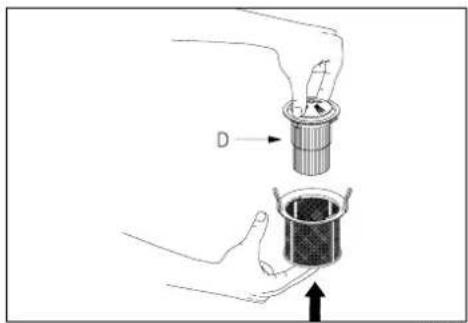
fig 16b

natural_image
Technical diagram showing a mechanical assembly with a lever and a circular component, no text or symbols present.fig. 15

fig. 16c
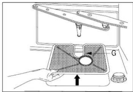
fig. 16d
natural_image
Isometric line drawing of a rectangular object with a small protrusion and a central hole, labeled 'fig. 17' (no text or symbols on the object itself)natural_image
Technical line drawing showing a door panel installation with a bracket and mounting bracket (no text or symbols)fig. 18a
natural_image
Technical line drawing of a mechanical assembly with an inset showing a detail (no text or symbols)fig. 18b
natural_image
Technical line drawing of a mechanical assembly with a tool and component, no visible text or symbolsfig. 19
natural_image
Technical line drawing of a structural panel assembly (no text or symbols)fig. 20
Note :

natural_image
Line drawing of a hand pouring a material into a funnel inside a vehicle (no text or symbols)Abb. 3
Wasserenthärter
natural_image
Illustration of a hand holding keys near a window with arrows indicating motion (no text or symbols)Abb. 4a
| Wasserhärte Einstellung | ||
| Deutsche Französische Härte Härte | ||
| 0 - 4 °dH 0 - | 7 °dF Position 1(kein Salz) | |
| 5 - 15 °dH 8 | - 25 °dF Position 1 | |
| 16 - 23 °dH 26 | - 40 °dF Position 2 | |
| 24 - 31 °dH 41 | - 60 °dF Position 3 | |
| 32 - 47 °dH 61 | - 80 °dF Position 4 | |
| 48 - 58 °dH | 81 - 100 °dF | Position 5 |

Abb. 4b
| Wasserhärte Einstellung | ||
| Deutsche Französische Härte Härte | ||
| 0 - 4 °dH 0 | - 7 °dF Position 1(kein Salz) | |
| 5 - 9 °dH 0 | - 18 °dF Position 1 | |
| 10 - 22 °dH 16 | - 37 °dF Position 2 | |
| 23 - 29 °dH 38 | - 50 °dF Position 3 | |
| 30 - 35 °dH 51 | - 60 °dF Position 4 | |
| 36 - 41 °dH 61 | - 70 °dF Position 5 | |
natural_image
Line drawing of a hand holding a tool interacting with a mechanical component (no text or symbols)Abb. 7

natural_image
Technical line drawing of a mechanical assembly with rollers and a bracket (no text or symbols)Abb. 8
natural_image
Technical line drawing of a mechanical assembly with no visible text or symbolsAbb. 9

natural_image
Illustration of a hand interacting with an electronic circuit board (no text or symbols visible)Abb. 10
natural_image
Cross-sectional diagram of a mechanical component with layered internal structure (no text or symbols)Abb. 11
natural_image
Isometric technical diagram of a mechanical assembly with no visible text or symbolsAbb. 12
natural_image
Diagram of a wire basket with two compartments and an upward arrow indicating motion (no text or symbols)Abb. 13
natural_image
Technical line drawing of a mechanical assembly with a bracket and a tool labeled 'R' (no text or symbols present)Abb. 14
natural_image
Technical diagram showing a mechanical assembly with a valve and a tray, no text or symbols presentAbb. 15
Abb. 16a

Abb. 16b

Abb. 16c

Abb. 16d
natural_image
Isometric line drawing of a rectangular object with a small protrusion and a central dot, labeled 'Abb. 17' (no text or symbols on the object itself)natural_image
Technical line drawing showing a door panel installation with a close-up view of the door (no text or symbols present)Abb. 18a
natural_image
Technical line drawing of a mechanical assembly with an inset showing a detail (no text or symbols)Abb. 18b
natural_image
Technical line drawing of a mechanical assembly with a tool and component, no visible text or symbolsAbb. 19
natural_image
Technical line drawing of a structural panel assembly (no text or symbols)Abb. 20
Bitte beachten:


- Waterontharder
- Geen water in de machine
- Let op:
- Appliance information A and B
- Control panel (fig. 2a and 2b)
- Personal preferences
- Audible signal
- Water pressure
- Display codes
- Introduction
- Table of contents GB
- Before using the appliance
- Things to watch out for
- Before you place kitchenware in the machine
- Environmental tips
- China ware
- Glass
- Cutlery
- Attention:
- Furthermore...
- Controls
- Salt, rinse-aid and detergent
- Water softener
- Topping-up the salt
- Adjustment of the water-softener
- Remark:
- Baskets
- Upper basket in the high position
- Upper basket in the low position
- Loading the top basket
- Loading the lower basket (see fig. 11)
- Cutlery container (see fig. 13)
- The first cycle (see fig. 2a/2b)
- End of programme
- Interruption in a running program
- Extra programmes (if available)
- Delaying the start time
- Economy programmes
- E button
- No drying (button)
- Half load (button)
- Error codes
- Trouble shooting
- The programme does not start
- No water in the appliance
- Programme interrupted
- The kitchenware is not clean
- Kitchenware not dry and not gleaming
- Whitish spots or streaks on the kitchenware
- Dried drops of water on the kitchenware
- Cleaning
- Spray arms
- Installation
- Electrical connection
- General
- Note:
- What else you should watch out for
- Building-in
- Adjusting the height
- Mounting
- Adjusting the spring tension (see fig. 19)
- Positioning (see fig. 20)
- Water outlet
- Aquastop
- Disposal of packaging and appliances
- Adoucisseur d'eau
- Demi-charge (touche 1/2 )
- Note :
- Wasserenthärter
- Bitte beachten:
Brand : Pelgrim
Model : GVW865
Category : Dishwasher