UT43103 - Saw HOMELITE - Free user manual and instructions
Find the device manual for free UT43103 HOMELITE in PDF.

User questions about UT43103 HOMELITE
0 question about this device. Answer the ones you know or ask your own.
Ask a new question about this device
Download the instructions for your Saw in PDF format for free! Find your manual UT43103 - HOMELITE and take your electronic device back in hand. On this page are published all the documents necessary for the use of your device. UT43103 by HOMELITE.
USER MANUAL UT43103 HOMELITE
UT43103 / 14 in. Electric Chain Saw
natural_image
Line drawing of a Honda electric chain saw with attached power outlet (no text or symbols)Your electric chain saw has been engineered and manufactured to Homelite's high standard for dependability, ease of operation, and operator safety. When properly cared for, it will give you years of rugged, trouble-free performance.

WARNING: To reduce the risk of injury, the user must read and understand the operator's manual before using this product.
Thank you for buying a Homelite product.
SAVE THIS MANUAL FOR FUTURE REFERENCE
■ Bar and Chain Combinations....30
■ Parts Ordering and Service .... Back Page
This product has many features for making its use more pleasant and enjoyable. Safety, performance, and dependability have been given top priority in the design of this product making it easy to maintain and operate.
* * *
Do not attempt to operate this unit until you have read thoroughly and understand completely all instructions, safety information, etc. contained in this manual. Failure to comply can result in accidents involving fire, electric shock, or serious personal injury.
READ ALL INSTRUCTIONS
BASIC SAFETY PRECAUTIONS
- Do not start cutting until you have a clear work area, secure footing, and a planned retreat path from the falling tree. Cluttered areas invite accidents.
- Keep ALL children, bystanders, visitors, and animals out of the work area while starting or cutting with the chain saw. Do not let visitors contact chain saw or extension cord.
■ Do not operate chain saw in explosive atmospheres, such as in the presence of flammable liquids, gases, or dust. Chain saws create sparks which may ignite the dust or fumes.
■ WARNING: Use outdoor extension cords marked SW-A, SOW-A, STW-A, STOW-A, SJW-A, SJTW-A, or SJTOW-A. These cords are rated for outdoor use and reduce the risk of electric shock. - Polarized Plugs. To reduce the risk of electric shock, this tool has a polarized plug (one blade is wider than the other). This plug will fit in a polarized outlet only one way. If the plug does not fit fully in the outlet, reverse the plug. If it still does not fit, contact a qualified electrician to install the proper outlet. Do not change the plug in any way.
■ Make sure your extension cord is in good condition. When using an extension cord, be sure to use one heavy enough to carry the current your product will draw. A wire gauge size (A.W.G.) of at least 14 is recommended for an extension cord 50 feet or less in length. A cord exceeding 100 feet is not recommended. If in doubt, use the next heavier gauge. The smaller the gauge number, the heavier the cord. An undersized cord will cause a drop in line voltage resulting in loss of power and overheating.
■ Inspect extension cords periodically and, if damaged, have repaired by a licensed electrician. Constantly stay aware of cord location. Following this rule will reduce the risk of electric shock or fire.
■ Dress Properly - Wear snug fitting clothing. Always wear heavy, long pants, long sleeves, overalls, jeans or chaps made of cut resistant material or ones that contain cut resistant inserts. Wear non-slip safety footwear. Wear non-slip heavy duty gloves to improve your grip and to protect your hands. Do not wear jewelry, short pants, sandals, or go barefoot. Do not wear loose fitting clothing, which could be drawn into the motor or catch the chain or underbrush. Secure hair so it is above shoulder level. Wear hearing and head protection.
■ Heavy protective clothing may increase operator fatigue, which could lead to heat stroke. During weather that is hot and humid, heavy work should be scheduled for early morning or late afternoon hours when temperatures are cooler.
■ Always wear eye protection with side shields marked to comply with ANSI Z87.1 as well as head protection when operating this equipment.
■ Always be aware of what you are doing when using the chain saw. Use common sense. Do not operate the chain saw when you are tired, ill, or under the influence of alcohol, drugs, or medication.
■ Do not expose the chain saw to rain.
■ Do not use the chain saw in damp or wet locations.
■ Always be aware of extension cord while operating chain saw. Take precautions to avoid tripping over cord. Keep cord away from chain and operator at all times. Never carry saw by the cord or pull it to disconnect from receptacle. Keep cord from oil and sharp edges.
■ Stay alert and pay attention to what you are doing. Use common sense when using this unit.
- Keep all parts of your body away from the saw chain when the unit is running.
■ Always carry the chain saw by the front handle with the unit unplugged and the guide bar and saw chain positioned to the rear. When
GENERAL SAFETY RULES
transporting your chain saw, use the appropriate guide bar scabbard.
■ Never let anyone use your chain saw who has not received adequate instructions in its proper use. This applies to rentals as well as privately owned saws.
■ Before you start the unit, make sure the saw chain is not contacting any object.
■ Stop the chain saw before setting it down.
■ To avoid accidental starting, never carry the unit with your finger on the switch trigger.
- Maintain the unit with care. Keep the cutting edge sharp and clean for best performance and to reduce the risk of injury. Follow instructions for lubricating and changing accessories.
- Keep handles dry, clean, and free of oil and grease.
- Do not operate a chain saw with one hand! Use a firm grip with thumbs and fingers encircling the chain saw handles. Serious injury to the operator, helpers, bystanders, or any combination of these persons may result from one-handed operation. A chain saw is intended for two-handed use.
■ Guard against electric shock - Avoid body contact with grounded surfaces such as metal pipes and wire fences. There is an increased risk of electric shock if your body is grounded.
- Do not operate a chain saw that is damaged, improperly adjusted, or not completely and securely assembled. Chain should slow to a stop when the switch trigger is released. If the chain continues to turn after the switch trigger has been released, have the unit serviced by your nearest Homelite service dealer.
- Check for damaged parts. Check for alignment of moving parts, binding of moving parts, breakage of parts, mounting, and any other conditions that may affect its operation. A guard or other part that is damaged should be properly repaired or replaced by an authorized service dealer unless otherwise indicated elsewhere in this manual.
■ All chain saw service, other than the items listed in the operation and maintenance sections,
should be performed by your nearest Homelite service dealer.
■ Always maintain a proper stance.
- Do not use chain saw if switch does not turn it on and off. Have defective switch replaced by authorized service center.
- Do not adapt your powerhead to a bow guide or use it to power any attachments or devices not listed for the saw.
■ Disconnect chain saw from power supply when not in use, before servicing, and when making adjustments and changing attachments, such as saw chain and guard.
■ Do not cut vines and/or small underbrush.
- Do not operate a chain saw in a tree, on a ladder, rooftop or scaffold; this is extremely dangerous.
NOTE: The size of the work area depends on the job being performed as well as the size tree or work piece involved. For example, felling a tree requires a larger work area than making bucking cuts.
■ Use extreme caution when cutting small size brush and saplings, because small material may catch the saw chain and be whipped toward you or pull you off balance.
■ When cutting a limb that is under tension, be alert for spring back so that you will not be struck when the tension in the wood fibers is released.
■ Do not force the chain saw. The job can be performed better and safer at the rate for which it was intended.
■ Always use the right product for your application. The chain saw should be used for cutting wood only. Never use the chain saw to cut plastic, masonry or non-wood building materials.
■ Do not use the chain saw for purposes not intended.
■ Store chain saw when not in use. Chain saw should be stored in a dry and high or locked area out of the reach of children. When storing chain saw place the scabbard on the bar and chain and store the chain saw in carrying case.
GENERAL SAFETY RULES
■ Save these instructions. Refer to them frequently and use them to instruct others who
may use this product. If you loan someone this product, loan them these instructions also.

WARNING:
Some dust created by power sanding, sawing, grinding, drilling, and other construction activities contains chemicals known to cause cancer, birth defects or other reproductive harm. Some examples of these chemicals are:
- lead from lead-based paints,
• crystalline silica from bricks and cement and other masonry products, and
• arsenic and chromium from chemically-treated lumber.
Your risk from these exposures varies, depending on how often you do this type of work. To reduce your exposure to these chemicals: work in a well ventilated area, and work with approved safety equipment, such as those dust masks that are specially designed to filter out microscopic particles.
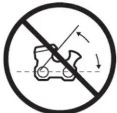
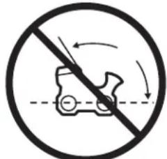
KICKBACK
See Figures 1 - 2.

WARNING:
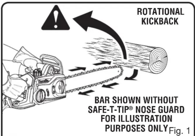
Kickback may occur when the moving chain contacts an object at the upper portion of the tip of the guide bar or when the wood closes in and pinches the saw chain in the cut. Contact at the upper portion of the tip of the guide bar can cause the chain to dig into the object and stop the chain for an instant. The result is a lightning fast, reverse reaction which kicks the guide bar up and back toward the operator. If the saw chain is pinched along the top of the guide bar, the guide bar can be driven rapidly back toward the operator. Either of these reactions can cause loss of saw control which can result in serious injury. Do not rely exclusively upon the safety devices built into the saw. As a chain saw user, you should take several steps to keep your cutting jobs free from accident or injury.
■ The following precautions should be followed to minimize kickback:
- Always grip the saw firmly with both hands. Hold the saw firmly with both hands when the unit is running. Place your right hand on the rear handle and your left hand on the front handle with your thumbs and fingers encircling the chain saw handles. A firm grip together with a stiff left arm will help you maintain control of the saw if kickback occurs.
text_image
ROTATIONAL KICKBACK BAR SHOWN WITHOUT SAFE-T-TIP® NOSE GUARD FOR ILLUSTRATION PURPOSES ONLYFig. 1
text_image
KICKBACK DANGER ZONE Fig. 2- Make sure that the area in which you are cutting is free from obstructions. Do not let the nose of the guide bar contact a log, branch, fence, or any other obstruction that could be hit while you are operating the saw.
- Always cut with the unit running. Fully squeeze the switch trigger and maintain cutting speed.
- Use replacement parts such as low kickback chain, SAFE-T-TIP® anti-kickback nose guards and special guide bars that reduce
GENERAL SAFETY RULES
the risks associated with rotational kickback. Use only the replacement guide bars and low kickback chains specified by the manufacturer for the saw.
■ With a basic understanding of kickback, you can reduce or eliminate the element of surprise. Sudden surprise contributes to accidents.
■ Do not overreach. Keep proper footing and balance at all times.
- Do not cut above shoulder height or overreach when cutting. Don't let nose of Guide Bar contact log, branch, ground or other obstruction.
- Keep the SAFE-T-TIP anti-kickback nose guard properly mounted on the guide bar to prevent rotational kickback.
■ Follow the sharpening and maintenance instructions for the saw chain.
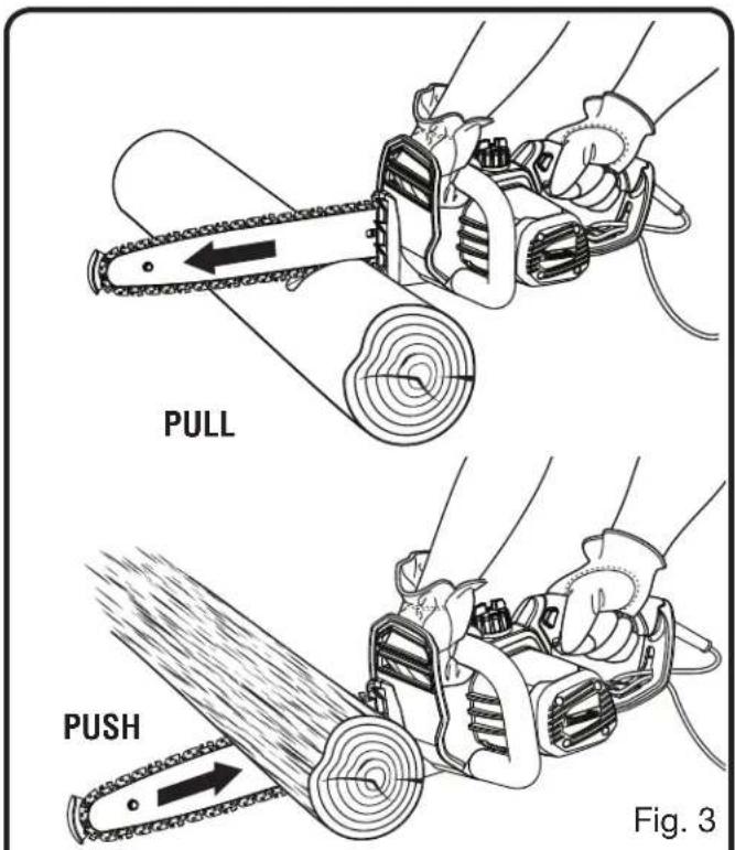
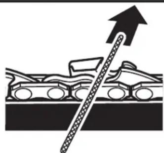
■ Push and Pull - This reaction force is always opposite to the direction the chain is moving where wood contact is made. Thus, the operator must be ready to control the PULL when cutting on the bottom edge of the bar, and PUSH when cutting along the top edge. See Figure 3.
UNDERSTANDING YOUR CHAIN SAW SAFETY DEVICES
See Figure 4.
SAFE-T-TIP® ANTI-KICKBACK NOSE GUARD
The SAFE-T-TIP ^® prevents rotational kickback from happening, because it covers the tip of the bar where kickback is generated. Never attempt any kind of cutting where the SAFE-T-TIP ^® would have to be removed from the bar tip.
The rakers (depth gauges) ahead of each cutter can minimize the force of a kickback reaction by preventing the cutters from digging in too deeply at the kickback zone. Only use replacement chain that is equivalent to original chain or has been certified as low kickback chain per ANSI B175.1.
Low kickback/skip tooth saw chain is a chain that has met the kickback performance requirements of ANSI B175.1 - 1991 (American National Standard for Power Tools - Gasoline-Powered Chain Saws-Safety Requirements) when tested on the representative sample of chain saws below 3.8 c.i.d. specified in ANSI B175.1 - 1991.
text_image
PULL PUSH Fig. 3
text_image
SAFE-T-TIP® Fig. 4As saw chains are sharpened during their useful life, they lose some of the low kickback qualities and extra caution should be used.
GUIDE BARS
Generally, guide bars with small radius tips have somewhat lower kickback potentials.
When making a replacement, be sure to order one of the Homelite bars listed for the saw in this operator's manual. The proper size SAFE-T-TIP® nose guard comes installed on the bar. Use only guide bars that have a provision for mounting the SAFE-T-TIP®.
SYMBOLS
| The following signal words and meanings are intended to explain the levels of risk associated with this product.SYMBOL SIGNAL MEANING | ||
 | DANGER: | Indicates an imminently hazardous situation, which, if not avoided, will result in death or serious injury. |
 | WARNING: | Indicates a potentially hazardous situation, which, if not avoided, could result in death or serious injury. |
 | CAUTION: | Indicates a potentially hazardous situation, which, if not avoided, may result in minor or moderate injury. |
| NOTICE: | (Without Safety Alert Symbol) Indicates a situation that may result in property damage. | |
| Some of the following symbols may be used on this product. Please study them and learn their meaning. Proper interpretation of these symbols will allow you to operate the product better and safer. SYMBOL NAME DESIGNATION/EXPLANATION | ||
 | Safety Alert Indicates a potential personal injury hazard. | |
 | Read The Operator's Manual | To reduce the risk of injury, user must read and understand operator's manual before using this product. |
 | Wear Eye and Head Protection | Always wear eye protection with side shields marked to comply with ANSI Z87.1, along with head protection. |
 | Wet Conditions Alert Do not expose to rain or use in damp locations. | |
 | SAFE-T-TIP Nose Guard | The SAFE-T-TIP nose guard on the guide bar helps prevent kickback. |
 | Operate With Two Hands Hold and operate the saw properly with both hands. | |
 | One Handed Do not operate the saw using only one hand. | |
 | Kickback DANGER! Beware of kickback. | |
 | Bar Nose Contact Avoid bar nose contact. | |
SYMBOLS
| Some of the following symbols may be used on this product. Please study them and learn their meaning. Proper interpretation of these symbols will allow you to operate the product better and safer. SYMBOL NAME DESIGNATION/EXPLANATION | ||
 | Wear Gloves | Wear non-slip, heavy-duty protective gloves when handling the chain saw. |
 | Wear Safety Footwear Wear non-slip safety footwear when using this equipment. | |
 | Keep Bystanders Away Keep all bystanders and animals at least 50 ft. away. | |
| V Volts Voltage | ||
| A Amperes Current | ||
| Hz Hertz Frequency (cycles per second) | ||
| W Watt Power | ||
| min Minutes Time | ||
| ~ | Alternating Current | Type of current |
| = | Direct Current | Type or a characteristic of current |
| n_0 | No Load Speed | Rotational speed, at no load |
| ☐ | Class II Construction | Double-insulated construction |
| .../min | Per Minute | Revolutions, strokes, surface speed, orbits etc., per minute |
ELECTRICAL
DOUBLE INSULATION
Double insulation is a concept in safety in electric power tools, which eliminates the need for the usual three-wire grounded power cord. All exposed metal parts are isolated from the internal metal motor components with protecting insulation. Double insulated tools do not need to be grounded.

WARNING:
The double insulated system is intended to protect the user from shock resulting from a break in the tool's internal insulation. Observe all normal safety precautions to avoid electrical shock.
NOTE: Servicing of a product with double insulation requires extreme care and knowledge of the system and should be performed only by a qualified service technician. For service, we suggest you return the product to your nearest authorized service center for repair. Always use original factory replacement parts when servicing.
ELECTRICAL CONNECTION
This product has a precision-built electric motor. It should be connected to a power supply that is 120V, AC only (normal household current), 60 Hz. Do not operate this product on direct current (DC). A substantial voltage drop will cause a loss of power and the motor will overheat. If the product does not operate when plugged into an outlet, double-check the power supply.
EXTENSION CORDS
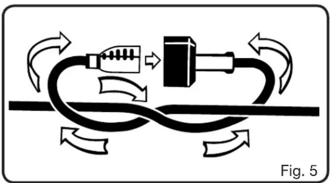
See Figure 5.
When using a power tool at a considerable distance from a power source, be sure to use an extension cord that has the capacity to handle the current the product will draw. An undersized cord will cause a drop in line voltage, resulting in overheating and loss of power. Use the chart to determine the minimum wire size required in an extension cord. Only round jacketed cords listed by Underwriter's Laboratories (UL) should be used.
When working outdoors with a product, use an extension cord that is designed for outside use. This type of cord is designated with “W-A” or “W” on the cord’s jacket.
Before using any extension cord, inspect it for loose or exposed wires and cut or worn insulation.
A proper extension cord is available at an authorized service center.
It is possible to tie the extension cord and power cord in a knot to prevent them from becoming disconnected during use. Make the knot as shown in figure 5, then connect the plug end of the power cord into the receptacle end of the extension cord. This method can also be used to tie two extension cords together.
natural_image
Diagram of a cable fastening process with directional arrows indicating flow (no text or symbols)**Ampere rating (on product data plate)
0-2.0 2.1-3.4 3.5-5.0 5.1-7.0 7.1-12.0 12.1-16.0
Cord Length Wire Size (A.W.G.)
| 25' | 16 | 16 | 16 | 16 | 14 | 14 |
| 50' | 16 | 16 | 16 | 14 | 14 | 12 |
| 100' | 16 | 16 | 14 | 12 | 10 | — |
**Used on 12 gauge - 20 amp circuit.
NOTE: AWG = American Wire Gauge

WARNING:
Keep the extension cord clear of the working area. Position the cord so that it will not get caught on lumber, tools, or other obstructions while you are working with a power tool. Failure to do so can result in serious personal injury.

WARNING:
Check extension cords before each use. If damaged replace immediately. Never use the product with a damaged cord since touching the damaged area could cause electrical shock resulting in serious injury.
GLOSSARY OF TERMS
Bar Tip Guard
An attachment that may be provided on the end of the guide bar to prevent the chain at the end of the guide bar from contacting the wood.
Bucking
The process of cross cutting a felled tree or log into lengths.
Chain Saw Powerhead
A chain saw without the saw chain and guide bar.
Clutch
A mechanism for connecting and disconnecting a driven member to and from a rotating source of power.
Drive Sprocket or Sprocket
The toothed part that drives the saw chain.
Felling
The process of cutting down a tree.
Felling Back Cut
The final cut in a tree felling operation made on the opposite side of the tree from the notching undercut.
Front Hand Guard
A structural barrier between the front handle of a chain saw and the guide bar, typically located close to the hand position on the front handle, and sometimes employed as an activating lever for a chain brake.
Front Handle
The support handle located at or toward the front of the chain saw. This handle is for the left hand.
Guide Bar
A solid railed structure that supports and guides the saw chain.
Kickback
The backward or upward motion, or both, of the guide bar occurring when the saw chain near the nose of the top area of the guide bar contacts any object such as a log or branch, or when the wood closes in and pinches the saw chain in the cut.
Kickback (Pinch)
The rapid pushback of the saw which can occur when the wood closes in and pinches the moving saw chain in the cut along the top of the guide bar.
Kickback (Rotational)
The rapid upward and backward motion of the saw which can occur when the moving saw chain near the upper portion of the tip of the guide bar contacts an object, such as a log or branch.
Low-Kickback Chain
A chain that complies with the kickback performance requirements of ANSI B175.1 when tested on a representative sample of chain saws.
Normal Cutting Position
Those positions assumed in performing the bucking and felling cuts.
Notching Undercut
A notch cut in a tree that directs the tree's fall.
Oiler Control
A system for oiling the guide bar and saw chain.
Rear Handle
The support handle located at or toward the rear of the saw. It normally contains the switch trigger. This handle is for the right hand.
Reduced Kickback Guide Bar
A guide bar which has been demonstrated to reduce kickback significantly.
Replacement Saw Chain
A chain that complies with the kickback performance requirements of ANSI B175.1 when tested with specific chain saws. It may not meet the ANSI performance requirements when used with other saws.
Saw Chain
A loop of chain having cutting teeth that cut the wood, and that is driven by the motor and is supported by the guide bar.
Spiked Bumper (Spike)
The pointed tooth or teeth for use when felling or bucking to pivot the saw and maintain position while sawing.
Switch Trigger
A device that when operated will complete or interrupt an electrical power circuit to the motor of the chain saw.
Switch Linkage
The mechanism that transmits motion from a trigger to the switch.
Switch Lock-out
A movable stop that prevents the unintentional operation of the switch until manually actuated.
FEATURES
PRODUCT SPECIFICATIONS
UT43103
Bar length....14 in.
Chain pitch .... 375 in.
Chain gauge .050 in.
Chain type ....Low Profile Skip Tooth
Drive sprocket 7-tooth
Input 120 V, AC only, 60 Hz, 9 Amps
Chain oil tank capacity....6 oz.
Weight - No bar, chain, or lubricant....7.8 lbs.
text_image
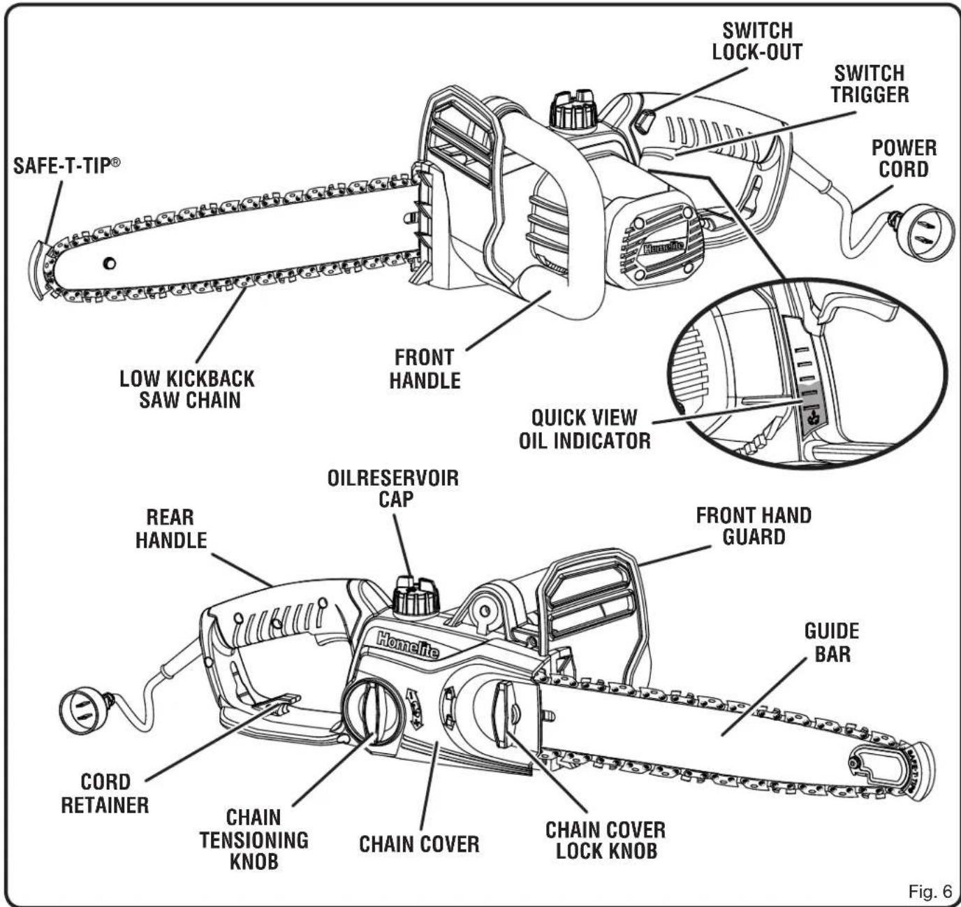
SAFE-T-TIP® SWITCH LOCK-OUT SWITCH TRIGGER POWER CORD LOW KICKBACK SAW CHAIN FRONT HANDLE QUICK VIEW OIL INDICATOR OILRESERVOIR CAP REAR HANDLE Homelife CHAIN TENSIONING KNOB CHAIN COVER CHAIN COVER LOCK KNOB CORD RETAINER GUIDE BAR Figure 6FEATURES
KNOW YOUR CHAIN SAW
See Figure 6.
The safe use of this product requires an understanding of the information on the tool and in this operator's manual as well as a knowledge of the project you are attempting. Before use of this product, familiarize yourself with all operating features and safety rules.
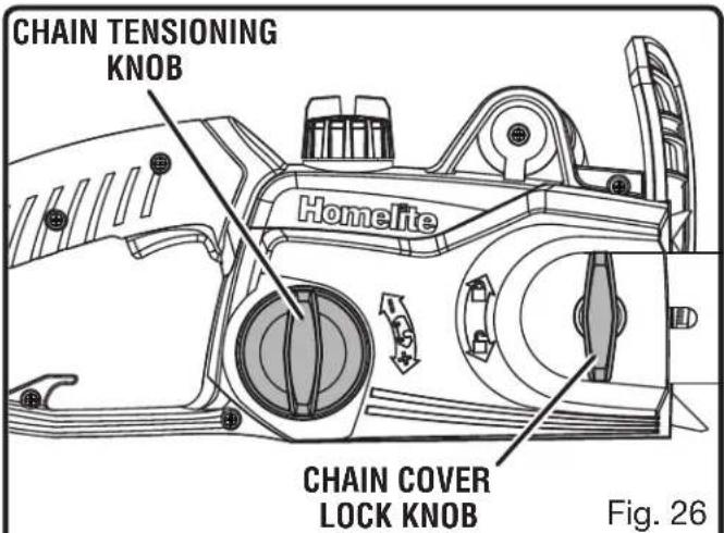
CHAIN TENSIONING KNOB
This feature allows user to adjust the tension of the chain.
GUIDE BAR
The factory-equipped guide bar has a small radius tip that offers a somewhat lower kickback potential.
The low kickback saw chain helps minimize the force of a kickback reaction by preventing the cutters from digging in too deeply at the kickback zone.
QUICK VIEW OIL INDICATOR
Semi-transparent oil reservoir that allows user to see when to add oil.
SAFE-T-TIP® ANTI-KICKBACK NOSE GUARD
The Safe-T-Tip® Anti-Kickback Nose Guard is an attach-ment provided on the end of the guide bar to prevent the chain on the end of the guide bar from contacting the wood.
SWITCH LOCK-OUT
A control feature designed to prevent the motor from being accidentally started.
SWITCH TRIGGER
Squeeze the switch trigger to operate the unit after switch lock-out has been pushed in. Release the switch trigger to stop the unit.
ASSEMBLY
UNPACKING
This product has been shipped completely assembled.
■ Carefully remove the product and any accessories from the box. Make sure that all items listed in the packing list are included.

WARNING:
Do not use this product if any parts on the Packing List are already assembled to your product when you unpack it. Parts on this list are not assembled to the product by the manufacturer and require customer installation. Use of a product that may have been improperly assembled could result in serious personal injury.
■ Inspect the product carefully to make sure no breakage or damage occurred during shipping.
■ Do not discard the packing material until you have carefully inspected and satisfactorily operated the product.
■ If any parts are damaged or missing, please call 1-800-242-4672 for assistance.
PACKING LIST
Chain Saw
Sleeve
Operator's Manual

WARNING:
If any parts are damaged or missing do not operate this product until the parts are replaced. Use of this product with damaged or missing parts could result in serious personal injury.
ASSEMBLY

WARNING:
Do not attempt to modify this product or create accessories not recommended for use with this product. Any such alteration or modification is misuse and could result in a hazardous condition leading to possible serious personal injury.

WARNING:
Do not connect to power supply until assembly is complete. Failure to comply could result in accidental starting and possible serious personal injury.
OPERATION

DANGER:
Never use near power lines or other electric sources. Contact with power lines or electric sources will result in death by electrocution or serious injury.

WARNING:
Do not allow familiarity with this product to make you careless. Remember that a careless fraction of a second is sufficient to inflict serious injury.

WARNING:
Always wear eye protection with side shields marked to comply with ANSI Z87.1, along with head protection. Failure to do so could result in objects being thrown into your eyes and other possible serious injuries.

WARNING:
Do not use any attachments or accessories not recommended by the manufacturer of this product. The use of attachments or accessories not recommended can result in serious personal injury.
APPLICATIONS
You may use this product for the purposes listed below:
■ Basic limbing, felling, and woodcutting
■ Removing buttress roots

text_image
CHAIN LUBRICANT OIL RESERVOIR CAP QUICK VIEW OIL INDICATOR Fig. 7ADDING BAR AND CHAIN LUBRICANT
See Figure 7
Use HOMELITE Bar and Chain Lubricant. It is designed for chains and chain oilers, and is formulated to perform over a wide temperature range with no dilution required.
NOTE: Chain saw comes from the factory with no bar and chain oil added. Level should also be checked after every 20 minutes of use and refilled as needed.
■ Remove oil cap.
■ Carefully pour the bar and chain oil into the tank.
■ Wipe off excess oil.
- Check and fill the oil tank when quick view oil indicator is below the second to last indicator line.
■ Repeat as needed.
NOTE: Do not use dirty, used or otherwise contaminated oils. Damage may occur to the bar or chain.
OPERATION
NOTE: It is normal for oil to seep from the saw when not in use. To prevent seepage, empty the oil tank after each use then run for one minute. When storing the unit for a long period of time (three months or longer) be sure the chain is lightly lubricated; this will prevent rust on the chain and bar sprocket.
CONNECTING TO POWER SUPPLY
See Figure 8
This chain saw is designed with a cord retainer that prevents the extension cord from being pulled loose while using.
■ Form a loop with the end of the extension cord.
■ Insert loop portion of extension cord through the opening in the side of the rear handle and place over cord hitch.
■ Slowly pull loop against cord retainer until the slack is removed.
- Plug chain saw into extension cord.
NOTE: Failure to remove all excess cord slack from extension cord retainer could result in plug loosening from receptacle.
STARTING AND STOPPING THE CHAIN SAW
See Figure 9.

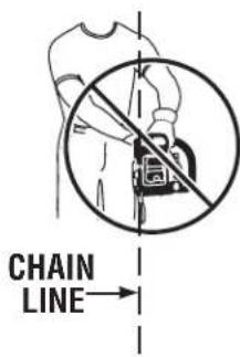
WARNING:
Keep body to the left of the chain line. Never straddle the saw or chain, or lean over past the chain line.
Starting the chain saw:
■ Make sure chain tension is at desired setting. Refer to Adjusting the Chain Tension in the Maintenance section of this manual.
■ Make sure the chain cover lock knob is tight to the chain cover.
■ Make sure no objects or obstructions are in immediate vicinity which could come in contact with the bar and chain.
■ Press and hold the switch lock-out. This makes the switch trigger operational.
■ Press and hold the switch trigger, release the switch lock-out and continue to squeeze the switch trigger for continued operation.

text_image
RETENUE DE CORDON EXTENSION CORD Fig. 8
text_image
SWITCH LOCK-OUT SWITCH TRIGGER Homelite Fig. 9Stopping the chain saw:
NOTE: It is normal for the chain to coast to a stop once the trigger switch is released.
■ Release the switch trigger to stop the chain saw.
■ Upon release of the switch trigger, the switch lock-out will be automatically reset to the lock position.
PREPARING FOR CUTTING PROPER GRIP ON HANDLES
See Figure 10.
See General Safety Rules for appropriate safety equipment.
■ Wear non-slip gloves for maximum grip and protection.
■ Hold the saw firmly with both hands. Always keep your left hand on the front handle and your right hand on the rear handle so that your body is to the left of the chain line.
OPERATION

WARNING:
Never use a left-handed (cross-handed) grip or any stance that would place your body or arm across the chain line.
- Maintain a proper grip on the saw whenever the motor is running. The fingers should encircle the handle and the thumb is wrapped under the handlebar. This grip is least likely to be broken by a kickback or other sudden reaction of the saw. Any grip in which the thumb and fingers are on the same side of the handle is dangerous because a slight kick of the saw can cause loss of control.

WARNING:
DO NOT operate the switch trigger with your left hand and hold the front handle with your right hand. Never allow any part of your body to be in the chain line while operating a saw. Improper operation of the chain saw could result in serious personal injury.
text_image
CHAIN LINE →PROPER CUTTING STANCE
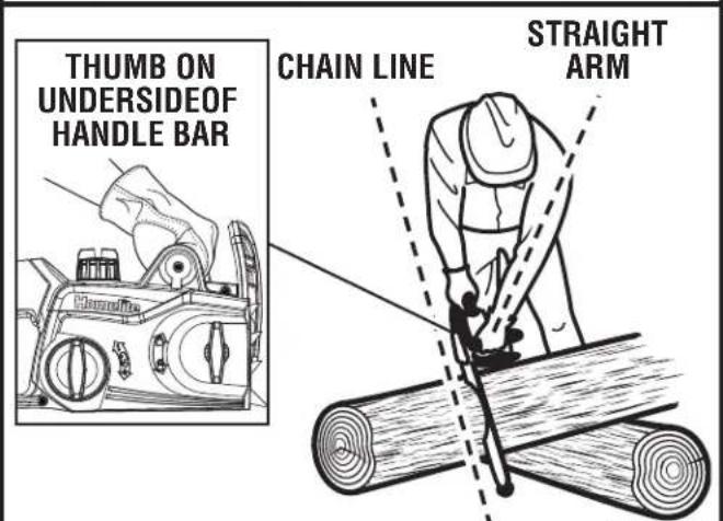
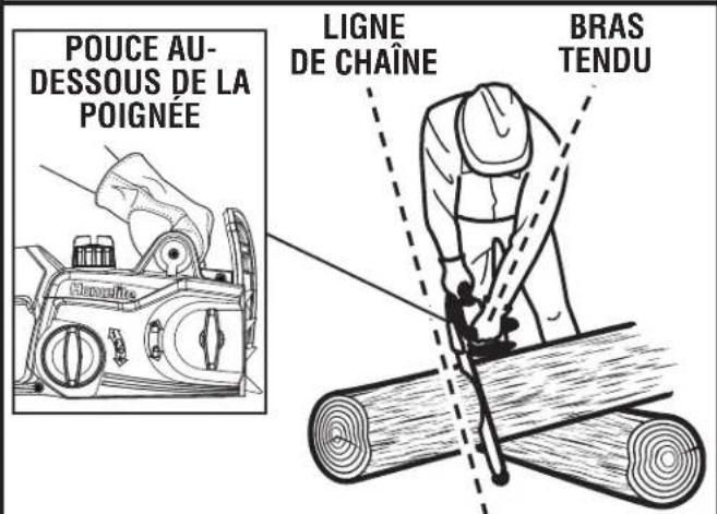
See Figure 11.

WARNING:
Always use the proper cutting stance described in this section. Never kneel when using the chain saw, except when felling a tree as illustrated in Figure 12. Kneeling could result in loss of stability and control of the chain saw, resulting in serious personal injury.
■ Balance your weight with both feet on solid ground.
- Keep left arm with elbow locked in a “straight arm” position to withstand any kickback force.
- Keep your body to the left of the chain line.
- Keep your thumb on underside of handlebar.

text_image
PROPER HAND GRIP POSITION PROPER GRIP IMPROPER GRIP Hamelife HamelifeFig. 10
text_image
THUMB ON UNDERSIDEOF HANDLE BAR CHAIN LINE STRAIGHT ARMFig. 11
BASIC OPERATING/CUTTING PROCEDURES
Practice cutting a few small logs using the following technique to get the "feel" of using the saw before you begin a major sawing operation.
■ Take the proper stance in front of the wood with the saw idling.
OPERATION
■ Press the switch lock-out and squeeze the switch trigger then release switch lock-out and let the chain accelerate to full speed before entering the cut.
■ Begin cutting with the saw against the log.
- Keep the unit running the entire time you are cutting, maintain a steady speed.
- Allow the chain to cut for you; exert only light downward pressure. Forcing the cut could result in damage to the bar, chain, or motor.
■ Release the switch trigger as soon as the cut is completed, allowing the chain to stop. If you run the saw without a cutting load, unnecessary wear can occur to the chain, bar, and unit.
■ Do not put pressure on the saw at the end of the cut.
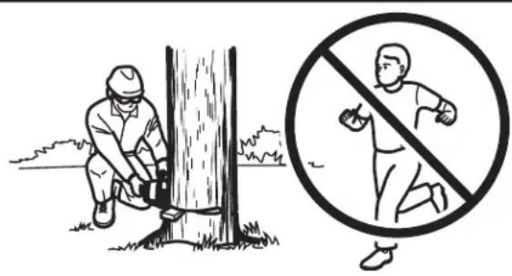
WORK AREA PRECAUTIONS
See Figure 12.
- Cut only wood or materials made from wood; no sheet metal, no plastics, no masonry, no non-wood building materials.
- Never allow children to operate the saw. Allow no person to use this chain saw who has not read this operator's manual or received adequate instructions for the safe and proper use of this chain saw.
- Keep everyone – helpers, bystanders, children, and animals – a SAFE DISTANCE from the cutting area. During felling operations, the safe distance should be a least twice the height of the largest trees in the felling area. During bucking operations, keep a minimum distance of 15 feet between workers.
■ Always cut with both feet on solid ground to prevent being pulled off balance.
■ Do not cut above shoulder height as a saw held higher is difficult to control against kickback forces.
■ Do not fell trees near electrical wires or buildings. Leave this operation for professionals. - Cut only when visibility and light are adequate for you to see clearly.
text_image
Illustration showing a worker using a tree to cut the tree with a prohibition symbol indicating no running or blocking.Fig. 12
FELLING TREES
HAZARDOUS CONDITIONS

WARNING:
Do not fell trees during periods of high wind or heavy precipitation. Wait until the hazardous weather has ended.
When felling a tree, it is important that you heed the following warnings to prevent possible serious injury.
- Do not cut down trees having an extreme lean or large trees with rotten limbs, loose bark, or hollow trunks. Have these trees pushed or dragged down with heavy equipment, then cut them up.
■ Do not cut trees near electrical wires or buildings. - Check the tree for damaged or dead branches that could fall and hit you during felling.
■ Periodically glance at the top of the tree during the backcut to assure the tree is going to fall in the desired direction.
If the tree starts to fall in the wrong direction, or if the saw gets caught or hung up during the fall, leave the saw and save yourself!
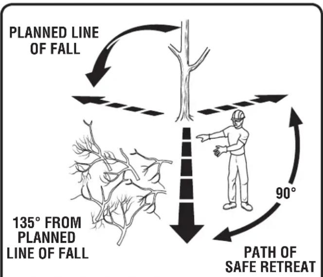
PROPER PROCEDURE FOR TREE FELLING
See Figures 13 - 16.
■ Felling a tree — When bucking and felling operations are being performed by two or more persons, at the same time, the felling operation should be separated from the bucking operation
OPERATION
by a distance of at least twice the height of the tree being felled. Trees should not be felled in a manner that would endanger any person, strike any utility line or cause any property damage. If the tree does make contact with any utility line, the utility company should be notified immediately.
■ Operator should keep on the uphill side of terrain as the tree is likely to roll or slide after it is felled.
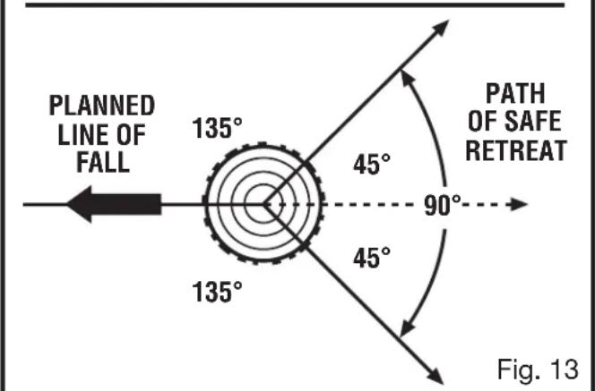
- Pick your escape route (or routes in case the intended route is blocked). Clear the immediate area around the tree and make sure there are no obstructions in your planned path of retreat. Clear the path of safe retreat approximately 135° from the planned line of fall.
■ Consider the force and direction of the wind, the lean and balance of the tree, and the location of large limbs. These things influence the direction in which the tree will fall. Do not try to fell a tree along a line different from its natural line of fall.
■ Remove dirt, stones, loose bark, nails, staples, and wire from the tree where felling cuts are to be made.
■ Notched Undercut. Cut a notch about 1/3 the diameter of the trunk in the side of the tree. Make the notch cuts so they intersect at a right angle to the line of fall. This notch should be cleaned out to leave a straight line. To keep the weight of the wood off the saw, always make the lower cut of the notch before the upper cut.
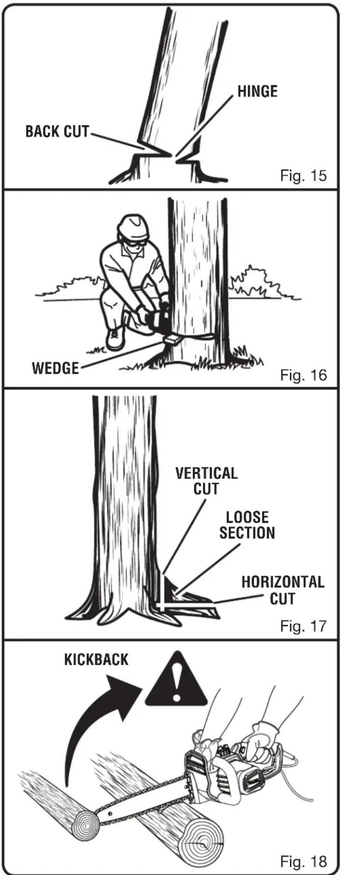
■ Felling Backcut. As the felling cut gets close to the hinge the tree should begin to fall. If there is any chance the tree may not fall in the desired direction or it may rock back and bind the saw chain, stop cutting before the felling cut is complete and use wedges of wood, plastic or aluminum to open the cut and drop the tree along its desired line of fall. Make the backcut level and horizontal, and at a minimum of 2 in. above the horizontal cut of the notch.
NOTE: Never cut through to the notch. Always leave a band of wood between the notch and back cut (approximately 2 in. or 1/10 the diameter of the tree). This is called “hinge” or “hingewood.” It controls the fall of the tree and prevents slipping or twisting or shootback of the tree off the stump.
flowchart
graph TD
    A["Planned Line of Fall"] --> B["Tree"]
    B --> C["Path of Safe Retreat"]
    C --> D["135° FROM PLANNED LINE OF FALL"]
    D --> E["90° Arrow"]
    style A fill:#f9f,stroke:#333
    style B fill:#ccf,stroke:#333
    style C fill:#cfc,stroke:#333
    style D fill:#fcc,stroke:#333
    style E fill:#ffc,stroke:#333
text_image
PLANNED LINE OF FALL 135° 45° 90° PATH OF SAFE RETREAT 135° 45° Fig. 13
text_image
HINGE 2 in. OR 1/10 DIA NOTCH - APPROX.1/3 DIAMETER OF TRUNK BACK CUT 2 in. Fig. 14- On large diameter trees, stop the back cut before it is deep enough for the tree to either fall or settle back on the stump. Then insert soft wooden or plastic wedges into the cut so they do not touch the chain. Drive wedges in, little by little, to help jack the tree over.
OPERATION
■ When bucking or felling with a wedge, it may be necessary to remove the SAFE-T-TIP anti-kickback device to allow the bar to be drawn through the cut. After you complete the cut, reinstall the tip immediately.
As tree starts to fall, stop the chain saw and put it down immediately. Retreat along the cleared path, but watch the action in case something falls your way.
■ Be alert for overhead limbs falling and watch your footing.

WARNING:
Never cut through to the notch when making a back cut. The hinge controls the fall of the tree, this is the section of wood between the notch and backcut.
REMOVING BUTTRESS ROOTS
See Figure 17.
A buttress root is a large root extending from the trunk of the tree above the ground. Remove large buttress roots prior to felling. Make the horizontal cut into the buttress first, followed by the vertical cut. Remove the resulting loose section from the work area. Follow the correct tree felling procedure as stated in Proper Procedure For Tree Felling after you have removed the large buttress roots.
BUCKING
See Figure 18.
Bucking is the term used for cutting a fallen tree to the desired log length.
■ Always make sure your footing is secure and your weight is distributed evenly on both feet.
■ Cut only one log at a time.
■ Support small logs on a saw horse or another log while bucking.
- Keep a clear cutting area. Make sure that no objects can contact the guide bar nose and chain during cutting, this can cause kickback. To avoid the danger, keep the SAFE-T-TIP anti-kickback device attached while cutting. Refer to Kickback earlier in this manual.
OPERATION
When bucking on a slope, always stand on the uphill side of the log. To maintain complete control of the chain saw when cutting through the log, release the cutting pressure near the end of the cut without relaxing your grip on the chain saw handles. Do not let the chain contact the ground. After completing the cut, wait for the saw chain to stop before you move the chain saw. Always stop the motor before moving from tree to tree.
BUCKING WITH A WEDGE
See Figure 19.
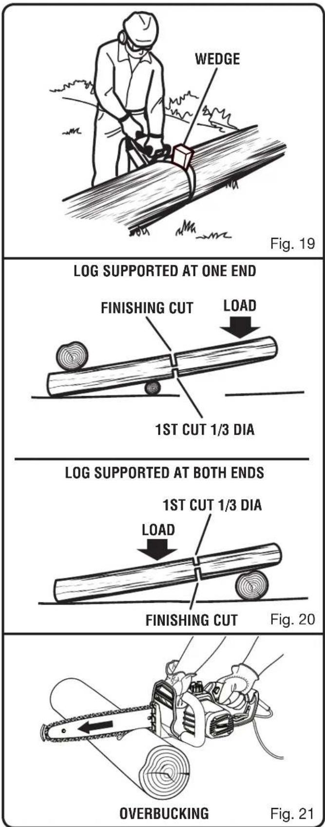
If the wood diameter is large enough for you to insert a soft bucking wedge without touching the chain, you should use the wedge to hold the cut open to prevent pinching.
NOTE: When bucking or felling with a wedge, you may need to remove the SAFE-T-TIP anti-kickback device to allow the bar to be drawn through the cut. After you complete the cut, reinstall the tip.
BUCKING LOGS UNDER STRESS
See Figure 20.
Make the first bucking cut 1/3 of the way through the log and finish with a 2/3 cut on the opposite side. As you cut the log, it will tend to bend. The saw can become pinched or hung in the log if you make the first cut deeper than 1/3 of the diameter of the log.
Give special attention to logs under stress to prevent the bar and chain from pinching.
OVERBUCKING
See Figure 21.
Begin on the top side of the log with the bottom of the saw against the log; exert light pressure downward. Note that the saw will tend to pull away from you.
text_image
WEDGE Fig. 19 LOG SUPPORTED AT ONE END FINISHING CUT LOAD 1ST CUT 1/3 DIA LOG SUPPORTED AT BOTH ENDS 1ST CUT 1/3 DIA LOAD FINISHING CUT Fig. 20 OVERBUCKING Fig. 21OPERATION
UNDERBUCKING
See Figure 22.
Begin on the under side of the log with the top of the saw against the log; exert light pressure upward. During underbucking, the saw will tend to push back at you. Be prepared for this reaction and hold the saw firmly to maintain control.
LIMBING
See Figure 23.
Limbing is removing branches from a fallen tree.
■ Work slowly, keeping both hands on the chain saw with a firm grip. Always make sure your footing is secure and your weight is distributed evenly on both feet.
■ Leave the larger support limbs under the tree to keep the tree off the ground while cutting.
■ Limbs should be cut one at a time. Remove the cut limbs from the work area often to help keep the work area clean and safe.
■ Branches under tension should be cut from the bottom up to avoid binding the chain saw.
- Keep the tree between you and the chain saw while limbing. Cut from the side of the tree opposite the branch you are cutting.
PRUNING
See Figure 24.
Pruning is trimming limbs from a live tree.
■ Work slowly, keeping both hands on the chain saw with a firm grip. Always make sure your footing is secure and your weight is distributed evenly on both feet.
■ Do not cut from a ladder, this is extremely dangerous. Leave this operation for professionals.
■ Do not cut above shoulder height as a saw held higher is difficult to control against kickback.

OPERATION
■ When pruning trees it is important not to make the finishing cut next to the main limb or trunk until you have cut off the limb further out to reduce the weight. This prevents stripping the bark from the main member.
■ Underbuck the branch 1/3 through for your first cut.
- Your second cut should overbuck to drop the branch off.
■ Now make your finishing cut smoothly and neatly against the main member so the bark will grow back to seal the wound.

WARNING:
If the limbs to be pruned are above shoulder height, hire a professional to perform the pruning. Cutting above shoulder height could result in an accident, causing serious personal injury.
CUTTING SPRINGPOLES
See Figure 25.
A springpole is any log, branch, rooted stump, or sapling which is bent under tension by other wood so that it springs back if the wood holding it is cut or removed. On a fallen tree, a rooted stump has a high potential of springing back to the upright position during the bucking cut to separate the log from the stump. Watch out for springpoles — they are dangerous.

WARNING:
Springpoles are dangerous and could strike the operator, causing the operator to lose control of the chain saw. This could result in severe or fatal injury to the operator.
MAINTENANCE

WARNING:
Before performing any maintenance, make sure the tool is unplugged from the power supply. Failure to comply could result in accidental starting and possible serious personal injury.

WARNING:
When servicing, use only identical Homelite replacement parts. Use of any other parts may create a hazard or cause product damage.

WARNING:
Always wear eye protection with side shields marked to comply with ANSI Z87.1, along with head protection. Failure to do so could result in objects being thrown into your eyes and other possible serious injuries.
GENERAL MAINTENANCE
Avoid using solvents when cleaning plastic parts. Most plastics are susceptible to damage from various types of commercial solvents and may be damaged by their use. Use clean cloths to remove dirt, dust, lubricant, grease, etc.

WARNING:
Do not at any time let brake fluids, gasoline, petroleum-based products, penetrating lubricants, etc., come in contact with plastic parts. Chemicals can damage, weaken or destroy plastic which may result in serious personal injury.
LUBRICATION
All of the bearings in this product are lubricated with a sufficient amount of high grade lubricant for the life of the unit under normal operating conditions. Therefore, no further lubrication is required.
text_image
CHAIN TENSIONING KNOB Homelite CHAIN COVER LOCK KNOB Fig. 26
text_image
MOUNTING SURFACE BAR CHAIN CHAIN COVER CHAIN COVER LOCK KNOBFig. 27
REPLACING THE GUIDE BAR AND CHAIN
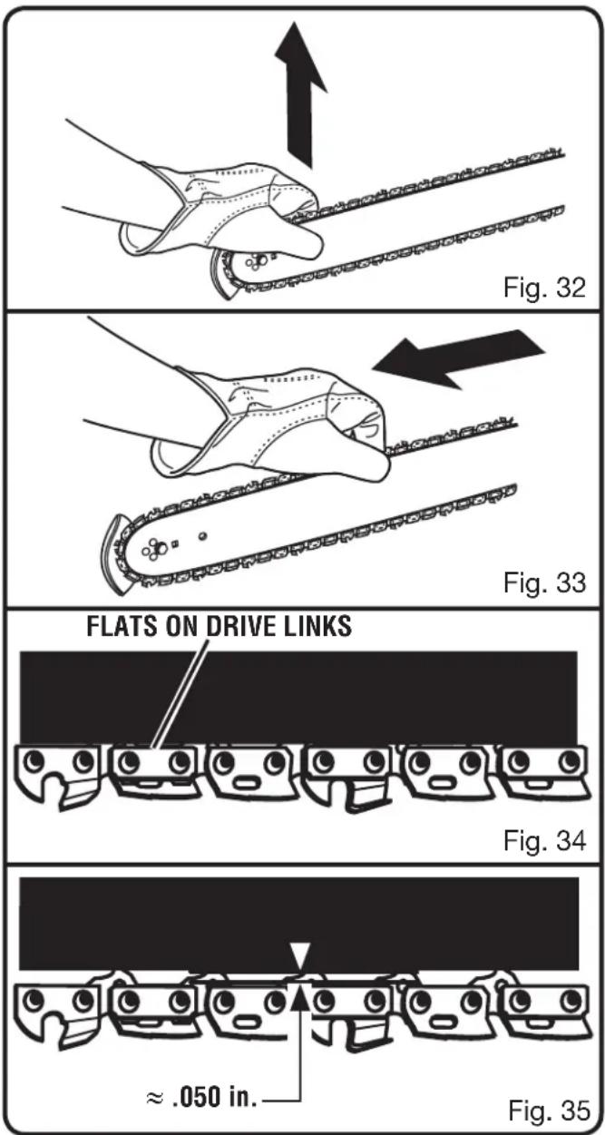
See Figures 26 - 33.

WARNING:
Never start the motor before installing the guide bar, chain, chain cover, and chain cover lock knob. Starting the motor without all parts and the chain at proper tension may result in serious personal injury.

WARNING:
To avoid serious personal injury, read and understand all the safety instructions in this section.
MAINTENANCE

CAUTION:
Always wear gloves when handling the bar and chain; these components are sharp and may contain burrs.

WARNING:
Never touch or adjust the chain while the motor is running. The saw chain is very sharp; always wear protective gloves when performing maintenance to the chain to avoid possible serious lacerations.

text_image
CUTTERS CHAIN ROTATION CHAIN DRIVE LINKS Fig. 28
text_image
BAR GROOVE CHAIN DRIVE LINKS Fig. 29
text_image
CHAIN TENSIONING PIN HOLE BAR STUDS CHAIN COVER CHAIN COVER LOCK KNOB CHAIN TENSIONING PIN Fig. 30
text_image
HomeLite CHAIN TENSIONING KNOB Fig. 31MAINTENANCE
NOTE: When replacing the guide bar and chain, always use the specified bar and chain listed in the Bar and Chain Combinations section later in this manual.
■ Disconnect chain saw from power supply.
■ Rotate the chain cover lock knob counterclockwise and remove knob.
■ Remove the chain cover.
■ Remove the bar and chain from the mounting surface.
■ Remove the old chain from the bar.
■ Lay out the new saw chain in a loop and straighten any kinks. The cutters should face in the direction of chain rotation. If they face backwards, turn the loop over.
■ Place the chain drive links into the bar groove as shown.
NOTE: Make certain of direction of chain.
■ Position the chain so there is a loop at the back of the bar.
■ Hold the chain in position on the bar and place the loop around the sprocket.
■ Fit the bar flush against the mounting surface so that the bar studs are in the long slot of the bar.

WARNING:
When placing the bar on the bar studs, ensure that the chain tensioning pin is in the chain tension pin hole. Failure to properly place the chain tensioning pin in the chain tensioning pin hole could cause the chain to come loose, resulting in serious personal injury.
■ Replace the chain cover.
■ Replace the chain cover lock knob; rotate knob clockwise to tighten. The bar should still be free to move for tension adjustment.
■ Remove all slack from the chain by turning the chain tensioning knob clockwise until the chain seats snugly against the bar with the drive links in the bar groove.
- Lift the tip of the guide bar up to check for sag.
- Release the tip of the guide bar and turn the chain tensioning knob 1/2 turn clockwise. Repeat this process until sag does not exist.
■ Hold the tip of the guide bar up and tighten the chain cover lock knob.
The chain is correctly tensioned when there is no sag on the underside of the guide bar, the chain is snug, but it can be turned by hand without binding.
NOTE: If chain is too tight, it will not rotate. Loosen the chain cover lock knob slightly and turn the chain tensioning knob 1/4 turn counterclockwise. Lift the tip of the guide bar up and retighten the chain cover lock knob. Ensure that the chain will rotate without binding.
MAINTENANCE
ADJUSTING THE CHAIN TENSION
See Figures 34 - 35.

WARNING:
Never touch or adjust the chain while the motor is running. The saw chain is very sharp. Always wear protective gloves when performing maintenance on the chain.
■ Stop the motor and disconnect from power supply before setting the chain tension.
■ Slightly loosen the chain cover lock knob.
■ Turn the chain tensioning knob clockwise to tension the chain.
NOTE: A cold chain is correctly tensioned when there is no slack on the underside of the guide bar, the chain is snug, and it can be turned by hand without binding.
■ Rotate the chain cover lock knob clockwise to secure.
Retention the chain whenever the flats on the drive links hang out of the bar groove.
NOTE: During normal saw operation, the temperature of the chain increases. The drive links of a correctly tensioned warm chain will hang approximately .050 in. out of the bar groove.
NOTE: New chains tend to stretch; check the chain tension frequently and tension as required.
NOTICE:
A chain tensioned while warm may be too tight upon cooling. Check the “cold tension” before next use.
CHAIN MAINTENANCE
See Figures 36 - 37.

WARNING:
Before performing any maintenance, make sure the tool is unplugged from the power supply. Failure to comply could result in accidental starting and possible serious personal injury.
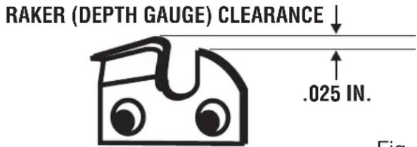
RAKER (DEPTH GAUGE) CLEARANCE

text_image
.025 in. Fig.Fig. 36
INSPECT DRIVE SPROCKET
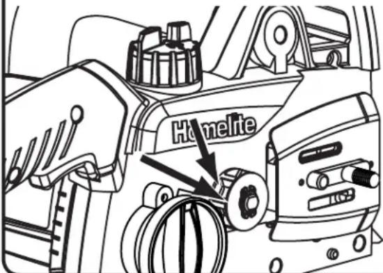
text_image
HämelteFig. 37
Use only a low-kickback chain on this saw. This fast-cutting chain provides kickback reduction when properly maintained.
For smooth and fast cutting, maintain the chain properly.
The chain requires sharpening when the wood chips are small and powdery, the chain must be forced through the wood during cutting, or the chain cuts to one side. During maintenance of the chain, consider the following:
■ Improper filing angle of the side plate can increase the risk of severe kickback.
■ Raker (depth gauge) clearance.
- Too low increases the potential for kick-back.
- Not low enough decreases cutting ability.
If the cutter teeth hit hard objects such as nails and stones, or are abraded by mud or sand on the wood, have an authorized service center sharpen the chain.
NOTE: Inspect the drive sprocket for wear or damage when replacing the chain. If signs of wear or damage are present in the areas indicated, have the drive sprocket replaced by an authorized service center.
MAINTENANCE
NOTE: If you do not fully understand the correct procedure for sharpening the chain after reading the instructions that follow, have the saw chain sharpened by an authorized service center or replace with a recommended low-kickback chain.
SHARPENING THE CUTTERS
See Figures 38 - 41.
Be careful to file all cutters to the specified angles and to the same length, as fast cutting can only be obtained when all cutters are uniform.

WARNING:
Before performing any maintenance, make sure the tool is unplugged from the power supply. Failure to comply could result in accidental starting and possible serious personal injury.

WARNING:
The saw chain is very sharp. Always wear protective gloves when performing maintenance to the chain to prevent serious personal injury.
■ Tension the chain prior to sharpening. Refer to Adjusting The Chain Tension.
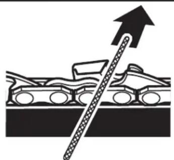
■ Use a 5/32 in. diameter round file and holder. Do all of your filing at the midpoint of the bar.
- Keep the file level with the top plate of the tooth. Do not let the file dip or rock.
■ Using light but firm pressure. Stroke towards the front corner of the tooth.
■ Lift the file away from the steel on each return stroke.
- Put a few firm strokes on every tooth. File all left hand cutters in one direction. Then move to the other side and file the right hand cutters in the opposite direction.
■ Remove filings from the file with a wire brush.
NOTICE:
A dull or improperly sharpened chain can cause excessive motor speed during cutting, which may result in severe motor damage.

text_image
CUTTING CORNER TOP PLATE SIDE PLATE RIVET HOLE DEPTH GAUGE HEEL TOE GULLET Fig. 38
natural_image
Mechanical assembly diagram showing a chain with a rod and an arrow indicating direction (no text or symbols)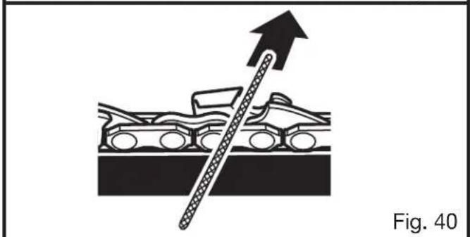
natural_image
Diagram showing a mechanical assembly with a rod inserted into a housing, labeled Fig. 40 (no text or symbols on the diagram itself)
text_image
LEFT HAND CUTTERS RIGHT HAND CUTTERS Fig. 41WARNING:
Improper chain sharpening increases the potential of kickback, which could result in serious personal injury.
MAINTENANCE

WARNING:
Failure to replace or repair a damaged chain could cause serious injury.
TOP PLATE FILING ANGLE
See Figure 42
■ CORRECT 30° – file holders are marked with guide marks to align file properly to produce correct top plate angle.
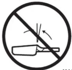
■ LESS THAN 30° – for cross cutting.
■ MORE THAN 30^ – feathered edge dulls quickly.
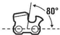
SIDE PLATE ANGLE
See Figure 43.
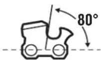
■ CORRECT 80° – Produced automatically if you use the correct diameter file in the file holder.
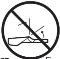
■ HOOK – “Grabs” and dulls quickly; increases the potential of KICKBACK. Results from using a file with a diameter too small or a file held too low.
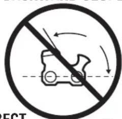
■ BACKWARD SLOPE – Needs too much feed pressure; causes excessive wear to the bar and chain. Results from using a file with a diameter too large or file held too high.
MAINTAINING DEPTH GAUGE CLEARANCE
See Figure 44 - 46.
- Maintain the depth gauge at a clearance of .025 in. Use a depth gauge tool for checking the depth gauge clearances.
■ Every time the chain is filed, check the depth gauge clearance.
■ Use a flat file and a depth gauge jointer to lower all gauges uniformly. Use a .025 in. depth gauge jointer. After lowering each depth gauge, restore original shape by rounding the front. Be careful not to damage adjoining drive links with the edge of the file.
■ Depth gauges must be adjusted with the flat file in the same direction the adjoining cutter was filed with the round file. Use care not to contact cutter face with flat file when adjusting depth gauges.
TOP PLATE FILING ANGLE

CORRECT
LESS THAN 30°
natural_image
Prohibition sign showing a crossed-out tool without any text or symbolsMORE THAN 30°
text_image
Fig. 2T Fig.INCORRECT
Fig. 42
SIDE PLATE FILING ANGLE
CORRECT
HOOK

text_image
Prohibition sign with a crossed-out robot icon and directional arrows, indicating no movement or safety warning.BACKWARD SLOPE
text_image
ECTINCORRECT
Fig. 43
text_image
RAKER (DEPTH GAUGE) CLEARANCE .025 IN. Fig.Fig. 44
DEPTH GAUGE JOINTER

text_image
FLAT FLOW FLAT FILEFig. 45
MAINTENANCE
MAINTAINING THE GUIDE BAR
See Figure 47.

WARNING:
Make sure the chain has stopped before you do any work on the saw.
Proper maintenance will maximize the useful life of the guide bar.
Each day of use:
Clean the bar and check for wear and damage. Feathering or burring of the bar rails is a normal process of bar wear, but such faults should be smoothed with a file as soon as they occur.
Each week of use:
■ Reverse the guide bar on the saw to distribute the wear.
■ Lubricate the socket at the end of the guide bar using a grease syringe in the lubricating hole.
■ Turn the guide bar and check that the lubrication holes and chain groove are free from impurities.
A bar with any of the following faults should be replaced immediately:
■ Wear inside the bar rails that permits the chain to lay over sideways
■ Bent guide bar
■ Cracked or broken rails
- Spread rails
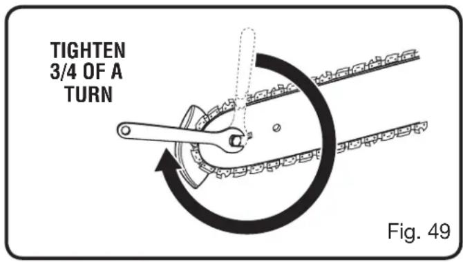
MOUNTING THE SAFE-T-TIP® NOSE GUARD
See Figures 48 - 49.
■ Disconnect chain saw from power supply.
■ Mount the SAFE-T-TIP on the bar nose.
■ Fit the locking rivet or tab in the recessed hole in the guide bar.
■ Tighten the screw with wrench until snug.
■ From the snug position, tighten the screw an additional 3/4 of a turn using a wrench.

MAINTAINING THE SAFE-T-TIP® NOSE GUARD
See Figures 47 - 48.

WARNING:
Although the guide bar comes with a SAFE-T-TIP antikickback device already installed, check the tightness of the mounting screw before each use to avoid possible serious personal injury.
MAINTENANCE
Use the following instructions to tighten the mounting screw of the nose guard. These are specially hardened screws. If you cannot install the screw tightly, replace both the screw and the SAFE-T-TIP before further operation.
NOTE: Do not replace the screw with an ordinary screw. Use only identical replacement parts from the manufacturer when replacing parts.
In addition to preventing chain contact with solid objects at the nose of the bar, the SAFE-T-TIP also helps keep the chain away from abrasive surfaces, such as the ground. Keep it on the right hand side of the bar where it will be between the chain and the ground during flush with ground cutting.
The mounting screw requires a 5/16 in. wrench (or adjustable wrench) to achieve the recommended torque of 35 to 45 in. lb. A torque within this range can be achieved by using the following method.
■ Tighten the screw with wrench until snug.
■ From the snug position, tighten the screw an additional 3/4 of a turn using a wrench.
STORING THE PRODUCT
■ Clean all foreign material from the product. Store it in a well-ventilated place that is inaccessible to children. Keep away from corrosive agents such as garden chemicals and de-icing salts.
text_image
TIGHTEN 3/4 OF A TURN Fig. 49BAR AND CHAIN COMBINATIONS
Chain specifications: .375 in. pitch, low profile skip tooth, .050 in. chain gauge
Length of Bar Guide Bar Part Number Chain Part Number Drive Links
14 in. 310625001 901212001 52
TROUBLESHOOTING
| Problem Possible Cause Solution | ||
| Bar and chain running hot and smoking. | Check chain tension for over tight conditionChain oil tank empty. | Tension chain. Refer to Adjusting Chain Tension earlier in this manual.Check oil tank. |
| Motor runs, but chain is not rotating. | Chain tension too tight.Check guide bar and chain assembly.Check guide bar and chain for damage. | Retention chain, Refer to Adjusting Chain Tension earlier in this manual.Refer to Replacing Bar and Chain earlier in this manual.Inspect guide bar and chain for damage. |
| Motor runs, chain rotates but does not cut. | Dull chain.Chain on backwards. | Sharpen chain.Reverse direction of chain. |
| Chain tensioning dial is difficult to turn. | Tip of guide bar is not raised.Chain cover lock knob is too tight. | Raise tip of guide bar while rotating tension adjustment dial.Press in the clutch cover lock knob and rotate counterclockwise to slightly loosen the clutch cover before attempting to adjust chain tension. |

text_image
NEED HELP CALL 1-800-242-4672 www.homelite.comCALL US FIRST
For any questions about operating or maintaining your product, call the Homelite® Help Line!
Your product has been fully tested prior to shipment to ensure your complete satisfaction.
WARRANTY
LIMITED WARRANTY STATEMENT
Homelite Consumer Products, Inc., (“Homelite”) warrants to the original retail purchaser that this HOMELITE brand outdoor product is free from defect in material and workmanship and agrees to repair or replace, at Homelite’s, discretion, any defective product free of charge within these time periods from the date of purchase.
■ Two years for all models if used for personal, family, or household use;
■ 90 days for any unit used for other purposes, such as rental or commercial.
This warranty extends to the original retail purchaser only and commences on the date of the original retail purchase.
Any part of the this product manufactured or supplied by Homelite and found in the reasonable judgment of Homelite to be defective in material or workmanship will be repaired or replaced without charge for parts and labor by a Homelite authorized service center.
The product, including any defective part, must be returned to an authorized service dealer within the warranty period. The expense of delivering the product to the dealer for warranty work and the expense of returning it back to the owner after repair or replacement will be paid by the owner. Homelite's responsibility in respect to claims is limited to making the required repairs or replacements and no claim of breach of warranty shall be cause for cancellation or rescission of the contract of sale of any HOMELITE brand product. Proof of purchase will be required by the dealer to substantiate any warranty claim. All warranty work must be performed by a Homelite authorized service center.
This warranty is limited to ninety (90) days from the date of original retail purchase for any HOMELITE brand product that is used for rental or commercial purposes, or any other income-producing purpose.
This warranty does not cover any HOMELITE brand product that has been subject to misuse, neglect, negligence, or accident, or that has been operated in any way contrary to the operating instructions as specified in this operator's manual. This warranty does not apply to any damage to the product that is the result of improper maintenance or to any product that has been altered or modified. The warranty does not extend to repairs made necessary by normal wear or by the use of parts or accessories which are either incompatible with the HOMELITE brand product or adversely affect its operation, performance, or durability. In addition, this warranty does not cover:
A. Tune-ups – Spark Plugs, Carburetor, Carburetor Adjustments, Ignition, Filters
B. Wear items – Bump Knobs, Outer Spools, Cutting Lines, Inner Reels, Starter Pulleys, Starter Ropes, Drive Belts, Tines, Felt Washers, Hitch Pins, Mulching Blades, Blower Fans, Blower and Vacuum Tubes, Vacuum Bags and Straps, Guide Bars, Saw Chains
Homelite reserves the right to change or improve the design of any HOMELITE brand product without assuming any obligation to modify any product previously manufactured.
ALL IMPLIED WARRANTIES ARE LIMITED IN DURATION TO THE STATED WARRANTY PERIOD. ACCORDINGLY, ANY SUCH IMPLIED WARRANTIES INCLUDING MERCHANTABILITY, FITNESS FOR A PARTICULAR PURPOSE, OR OTHERWISE, ARE DISCLAIMED IN THEIR ENTIRETY AFTER THE EXPIRATION OF THE APPROPRIATE TWO-YEAR, ONE-YEAR, OR NINETY-DAY WARRANTY PERIOD. HOMELITE'S OBLIGATION UNDER THIS WARRANTY IS STRICTLY AND EXCLUSIVELY LIMITED TO THE REPAIR OR REPLACEMENT OF DEFECTIVE PARTS AND HOMELITE DOES NOT ASSUME OR AUTHORIZE ANYONE TO ASSUME FOR THEM ANY OTHER OBLIGATION. SOME STATES DO NOT ALLOW LIMITATIONS ON HOW LONG AN IMPLIED WARRANTY LASTS, SO THE ABOVE LIMITATION MAY NOT APPLY TO YOU. HOMELITE ASSUMES NO RESPONSIBILITY FOR INCIDENTAL, CONSEQUENTIAL, OR OTHER DAMAGES INCLUDING, BUT NOT LIMITED TO, EXPENSE OF RETURNING THE PRODUCT TO AN AUTHORIZED HOMELITE SERVICE CENTER AND EXPENSE OF DELIVERING IT BACK TO THE OWNER, MECHANIC'S TRAVEL TIME, TELEPHONE OR TELEGRAM CHARGES, RENTAL OF A LIKE PRODUCT DURING THE TIME WARRANTY SERVICE IS BEING PERFORMED, TRAVEL, LOSS OR DAMAGE TO PERSONAL PROPERTY, LOSS OF REVENUE, LOSS OF USE OF THE PRODUCT, LOSS OF TIME, OR INCONVENIENCE. SOME STATES DO NOT ALLOW THE EXCLUSION OR LIMITATION OF INCIDENTAL OR CONSEQUENTIAL DAMAGES, SO THE ABOVE LIMITATION OR EXCLUSION MAY NOT APPLY TO YOU.
This warranty gives you specific legal rights, and you may also have other rights which vary from state to state.
This warranty applies to all HOMELITE brand products manufactured by or for Homelite and sold in the United States and Canada.
To locate your nearest Homelite authorized service center, dial 1-800-242-4672 or log on to our website at www.homelite.com.
NOTES
RÈGLES DE SÉCURITÉ GÉNÉRALES

AVERTISSEMENT :
text_image
Diagram showing a vehicle collision with an explosion symbol and directional arrows, likely illustrating a collision or collision scenario.ZONE DE
DANGER DE
REBOND
Fig. 2
natural_image
Diagram of a cable fastening process with a plug and connector, showing curved arrows indicating motion (no text or symbols)NOTE : AWG = American Wire Gauge

AVERTISSEMENT :
text_image
TENUE CORRECTE DES POIGNÉESTENUE INCORRECTE
PRISE CORRECTE

natural_image
Line drawing of a homelite device with handle and wheels (no text or symbols)
natural_image
Technical line drawing of a mechanical device with a hand holding a circular component, no text or symbols presentFig. 10
text_image
POUCE AU- DESSOUS DE LA POIGNÉE LIGNE DE CHAÎNE BRAS TENDUFig. 11
natural_image
Illustration of a worker using a tool to cut a tree trunk while running, with a no-smoking circle showing the person running (no text or symbols present)Fig. 12
TRONÇONNAGE AVEC COINS
Voir la figure 19.
natural_image
Mechanical assembly diagram showing a chain with a central rod and an upward arrow (no text or symbols)Fig. 39
natural_image
Diagram showing a car being towed with a diagonal rod, indicating force or motion (no text or symbols present)Fig. 40
natural_image
No crossed-out diagram of a tool without any text or symbolsINCORRECT
PLUS DE 30°

natural_image
No crossed-out diagram of a tool without any text or symbolsFig. 42
ANGLE D'AFFÛTAGE DE LA PLAQUE LATÉRALE
dotés
CORRECT
CROCHET
text_image
Prohibition sign with a car and directional arrows, indicating no movement or restrictionINCORRECT
ANGLE ARRIÈRE
natural_image
Prohibition sign showing a vehicle crossed out by a diagonal line, indicating no movement or restriction (no text present)Fig. 43
natural_image
Diagram of a cable fastening process with a plug and connector, showing curved arrows indicating motion (no text or symbols)natural_image
Illustration of a person using a power tool to cut tree bark with a prohibition symbol (no text or labels)Fig. 12
TALA DE ÁRBOLES CONDICIONES PELIGROSAS

ADVERTENCIA:
natural_image
Line drawing of a manual power saw cutting through a chain (no text or symbols)TRONZADO POR ARRIBA
Fig. 21
FUNCIONAMIENTO
TRONZADO POR ABAJO
Vea la figura 22.
natural_image
Diagram of a mechanical device with a diagonal line crossing it and an arrow pointing downward (no text or symbols)Fig. 39
natural_image
Diagram showing a mechanical component with an upward arrow, no text or symbols presentFig. 40

ADVERTENCIA:
The engine exhaust from this product contains chemicals known to the State of California to cause cancer, birth defects, or other reproductive harm.
CALIFORNIA PROPOSITION 65

AVERTISSEMENT :
For parts or service, contact your nearest Homelite authorized service dealer. Be sure to provide all relevant information when you call or visit. For the location of the authorized service dealer nearest you, please call 1-800-242-4672 or visit us online at www.homelite.com.
REPAIR PARTS
The model number of this product is found on a plate or label attached to the housing. Please record the serial number in the space provided below.
MODEL NO. UT43103
SERIAL NO.
