UT10680 - Saw HOMELITE - Free user manual and instructions
Find the device manual for free UT10680 HOMELITE in PDF.

User questions about UT10680 HOMELITE
0 question about this device. Answer the ones you know or ask your own.
Ask a new question about this device
Download the instructions for your Saw in PDF format for free! Find your manual UT10680 - HOMELITE and take your electronic device back in hand. On this page are published all the documents necessary for the use of your device. UT10680 by HOMELITE.
USER MANUAL UT10680 HOMELITE
To register your Homelite product, please visit: http://register.homelite.com/
Your chain saw has been engineered and manufactured to our high standard for dependability, ease of operation, and operator safety. When properly cared for, it will give you years of rugged, trouble-free performance.

WARNING: To reduce the risk of injury, the user must read and understand the operator's manual before using this product.
Thank you for buying a Homelite product.
SAVE THIS MANUAL FOR FUTURE REFERENCE
■ Specific Safety Rules 4-5
■ Bar and Chain Combinations....38
■ Parts Ordering and Service .... Back Page
This product has many features for making its use more pleasant and enjoyable. Safety, performance, and dependability have been given top priority in the design of this product making it easy to maintain and operate.
* * *
Read and understand all instructions. Failure to follow all instructions listed below, may result in electric shock, fire and/or serious personal injury.
READ ALL INSTRUCTIONS
-
Know your tool. Read the operator's manual carefully. Learn the saw's applications and limitations as well as the specific potential hazards related to this tool.
■ Kickback may occur when the nose or tip of the guide bar touches an object, or when the wood closes in and pinches the saw chain in the cut. Tip contact in some cases may cause a lightning-fast reverse reaction, kicking the guide bar up and back toward the operator. Pinching the saw chain along the top of the guide bar may push the guide bar rapidly back toward the operator. Either of these reactions may cause you to lose control of the saw, which could result in serious personal injury. Do not rely exclusively upon the safety devices built into the saw. As a chain saw user, you should take several steps to keep your cutting jobs free from accident or injury. -
With a basic understanding of kic you can reduce or eliminate the element of surprise. Sudden surprise contributes to accidents.
- Keep a good firm grip on the saw with both hands when the engine is running. Place your right hand on the rear handle and your left hand on the front handle with your thumbs and fingers encircling the chain saw handles. A firm grip together with a stiff left arm will help you maintain control of the saw if kickback occurs.
- Make sure that the area in w cutting is free from obstructions. DO NOT let the nose of the guide bar contact a log, branch, fence, or any other obstruction that could be hit while you are operating the saw.
- Cut at high engine speeds. Always cut with the engine running at full speed. Fully
squeeze the throttle trigger and maintain a steady cutting speed.
- Do not overreach or cut above chest height.
- Follow the manufacturer's sharpening a maintenance instructions for the saw chain.
- Only use replacement bars and cha specified by the manufacturer or the equivalent.
■ Do not operate a chain saw with one hand. Serious injury to the operator, helpers, bystanders, or any combination of these persons may result from one-handed operation. A chain saw is intended for two-handed use.
■ Do not operate a chain saw when you are fatigued. Fatigue causes carelessness. Be more cautious before rest periods and towards the end of your shift. Never operate a chain saw when you are tired or under the influence of medication, drugs, or alcohol.
■ Use safety footwear. Wear snug-fitting clothing, protective gloves, and eye, hearing, and head protection devices.
■ Heavy protective clothing may increase operator fatigue, which could lead to heat stroke. During weather that is hot and humid, heavy work should be scheduled for early morning or late afternoon hours when temperatures are cooler.
■ Do not stand on any unstable surface while using the chain saw, that includes ladders, scaffolds, trees, rooftops, etc.
■ Use caution when handling fuel. Move the chain saw at least 30 feet from the fueling point before starting the engine.
■ Do not allow other persons to be near the chain saw when starting or cutting with the chain saw. Keep bystanders and animals out of the work area.
■ Do not start cutting until you have a clear work area, secure footing, and a planned retreat path from the falling tree.
- Keep all parts of your body away from the saw chain when the engine is running.
■ Always carry the chain saw with the engine stopped and the chain brake engaged, the
GENERAL SAFETY RULES
guide bar and saw chain to the rear, and the muffler away from your body. When transporting the chain saw, use the appropriate guide bar scabbard.
- Do not operate a chain saw that is damaged, improperly adjusted, or not completely and securely assembled. Be sure that the saw chain stops moving when the throttle control trigger is released.
■ Shut off the engine before setting the chain saw down. Do not leave the engine running unattended. As an additional safety precaution, apply the chain brake prior to setting down the saw.
■ Use extreme caution when cutting small-size brush and saplings because slender material may catch the saw chain and be whipped toward you or pull you off balance.
■ When cutting a limb that is under tension, be alert for springback so that you will not be struck when the tension in the wood fibers is released. - Keep the handles dry, clean, and free of oil or fuelmixture.
■ Beware of carbon monoxide poisoning. Operate the chain saw only in well-ventilated areas.
■ Do not operate a chain saw in a tree unless you have been specifically trained to do so.
■ Do not cut from a ladder; this is extremely dangerous.
All chain saw service, other than the items listed in the instruction manual and all maintenance, should be performed by competent chain saw service personnel. (For example, if improper tools are used to remove the flywheel or if an improper tool is used to hold the flywheel in order to remove the clutch, structural damage to the flywheel could occur and subsequently could cause the flywheel to burst.)
■ Always have a fire extinguisher available when using chain saw.
■ Use only the replacement guide bars and low kickback chains specified for the saw.
■ Do not adapt the powerhead to a bow guide or use it to power any attachments or devices not listed for the saw.
The gas powered saw (or electrically powered saw) is classified by CSA as a Class 1C (or Class 2C) saw. It is intended for infrequent use by homeowners, cottagers, and campers, and for such general applications as clearing, pruning, cutting firewood, etc. It is not intended for prolonged use. Prolonged periods of operation can cause circulatory problems in the user's hands due to vibration. For such use, it may be appropriate to use a saw having an anti-vibration feature.
■ Save these instructions. Refer to them frequently and use to instruct other users. If you loan someone this product, loan them these instructions also.
SPECIFIC SAFETY RULES

WARNING:
The warnings, labels, and instructions found in this section of the operator's manual are for your safety. Failure to follow all instructions may result in serious personal injury.
■ Do not cut vines and/or small underbrush (a diameter of less than 3 in.).
■ Muffler surfaces are very hot during and after operation of the chain saw; keep all body parts
away from the muffler. Serious burns may occur if contact is made with the muffler.
■ Always hold the chain saw with both hands when the engine is running. Use a firm grip with thumbs and fingers encircling the chain saw handles.
■ Never let anyone use the chain saw who has not received adequate instructions in its proper use. This applies to rentals as well as privately owned saws.
SPECIFIC SAFETY RULES
■ Before you start the engine, make sure the saw chain is not contacting any object.
■ Wear snug-fitting clothing. Always wear heavy, long pants, long sleeves, boots, and gloves. Do not wear jewelry, short pants, sandals, or go barefoot. Do not wear loose fitting clothing, which could be drawn into the engine or catch the chain or underbrush. Wear overalls, jeans, or chaps made of cut-resistant material or ones that contain cut-resistant inserts. Secure hair so that it is above shoulder level.
■ Wear non-slip safety footwear and heavy-duty gloves to improve your grip and to protect your hands.
■ Wear eye protection with side shields marked to comply with ANSI Z87.1, along with hearing and head protection, when operating this equipment.
- Keep bystanders and animals out of the work area. Do not allow other persons to be nearby during starting or cutting with the chain saw.
NOTE: The size of the work area depends on the job being performed as well as the size tree or workpiece involved. For example, felling a tree requires a larger work area than making other cuts (i.e., bucking cuts, etc.).
- Keep SAFE-T-TIPanti-kickback nose guard properly mounted on the guide bar to prevent rotational kickback.
■ Follow the sharpening and maintenance instructions for the saw chain.
■ Never operate a chain saw that is damaged, improperly adjusted, or is not completely and securely assembled. Be sure that the saw chain stops moving when the throttle control trigger is released. If the saw chain moves at idle speed, the carburetor may need adjusting. Refer to Adjusting the Carburetor in the Maintenance section of this manual. If the saw chain still moves at idle speed after adjustment has been made, contact an authorized service center for adjustment and discontinue use until the repair is made.
This product is intended for infrequent use by homeowners and other occasional users for general applications such as clearing, pruning, cutting firewood, etc. It is not intended for prolonged use. Prolonged periods of operation can cause circulatory problems in the user's hands due to vibration. For such use, it may be appropriate to use a product having an anti-vibration feature.
REFUELING (DO NOT SMOKE!)
■ To reduce the risk of fire and burn injury, handle fuel with care. It is highly flammable.
■ Mix and store fuel in a container approved for gasoline.
■ Mix fuel outdoors where there are no sparks or flames.
■ Select bare ground, stop the engine, and allow it to cool before refueling.
■ Loosen the fuel cap slowly to release pressure and to keep fuel from escaping around the cap.
■ Tighten the fuel cap securely after refueling.
■ Wipe spilled fuel from the unit. Move 30 feet away from refueling site before starting engine.
■ Never attempt to burn off spilled fuel under any circumstances.
KICKBACK
■ Kickback is a dangerous reaction that can lead to serious injury. Do not rely only on the safety devices provided with the saw. As a chain saw user, you must take special safety precautions to help keep your cutting jobs free from accident or injury. See the General Safety Rules and Operation sections of this manual for added information on kickback and how to avoid serious personal injury.
SYMBOLS
| The following signal words and meanings are intended to explain the levels of risk associated with this product. SYMBOL SIGNAL MEANING | ||
 | DANGER: | Indicates an imminently hazardous situation, which, if not avoided, will result in death or serious injury. |
 | WARNING: | Indicates a potentially hazardous situation, which, if not avoided, could result in death or serious injury. |
 | CAUTION: | Indicates a potentially hazardous situation, which, if not avoided, may result in minor or moderate injury. |
| CAUTION: | (Without Safety Alert Symbol) Indicates a situation that may result in property damage. | |
SYMBOLS
| Some of the following symbols may be used on this product. Please study them and learn their meaning. Proper interpretation of these symbols will allow you to operate the product better and safer. SYMBOL NAME DESIGNATION/EXPLANATION | ||
 | Safety Alert Indicates a potential personal injury hazard. | |
 | Read Operator's Manual | To reduce the risk of injury, user must read and understand operator's manual before using this product. |
 | Wear Eye, Hearing, and Head Protection | Wear eye protection with side shields marked to comply with ANSI Z87.1 as well as hearing and head protection when operating this equipment. |
 | SAFE-T-TIP Nose Guard | The SAFE-T-TIP nose guard on the guide bar helps prevent rotational kickback. |
 | No Smoking No smoking, sparks, or open flame. | |
 | Operate With Two Hands | Hold and operate the saw properly with both hands. |
 | One Handed Do not operate the saw using only one hand. | |
 | Carbon Monoxide | Engines produce carbon monoxide which is an odorless, deadly poison. Do not operate in an enclosed area. |
 | Kickback DANGER! Beware of kickback. | |
 | Bar Nose Contact Avoid bar nose contact. | |
 | Wear Gloves | Wear non-slip, heavy-duty protective gloves when handling the chain saw. |
 | Wear Safety Footwear | Wear non-slip safety footwear when using this equipment. |
 | Gasoline and Lubricant | Use unleaded gasoline intended for motor vehicle use with an octane rating of 87 [(R + M)/2] or higher. This product is powered by a 2-cycle engine and requires pre-mixing gasoline and 2-cycle lubricant. |
 | Keep Bystanders Away Keep all bystanders and animals at least 50 ft. away. | |
GLOSSARY OF TERMS
Bucking
The process of cross cutting a felled tree or log into lengths.
Chain Brake
A device used to stop the saw chain.
Chain Saw Powerhead
A chain saw without the saw chain and guide bar.
Clutch
A mechanism for connecting and disconnecting a driven member to and from a rotating source of power.
Drive Sprocket or Sprocket
The toothed part that drives the saw chain.
Felling
The process of cutting down a tree.
Felling Back Cut
The final cut in a tree felling operation made on the opposite side of the tree from the notching undercut.
Front Hand Guard
A structural barrier between the front handle of a chain saw and the guide bar, typically located close to the hand position on the front handle, and sometimes employed as an activating lever for a chain brake.
Front Handle
The support handle located at or toward the front of the chain saw. This handle is for the left hand.
Guide Bar
A solid railed structure that supports and guides the saw chain.
Kickback
The backward or upward motion, or both, of the guide bar occurring when the saw chain near the nose of the top area of the guide bar contacts any object such as a log or branch, or when the wood closes in and pinches the saw chain in the cut.
Kickback (Pinch)
The rapid pushback of the saw which can occur when the wood closes in and pinches the moving saw chain in the cut along the top of the guide bar.
Kickback (Rotational)
The rapid upward and backward motion of the saw which can occur when the moving saw chain near the upper portion of the tip of the guide bar contacts an object, such as a log or branch.
Low-Kickback Chain
A chain that complies with the kickback performance requirements of ANSI B175.1 when tested on a representative sample of chain saws.
Normal Cutting Position
Those positions assumed in performing the bucking and felling cuts.
Notching Undercut
A notch cut in a tree that directs the tree's fall.
Rear Handle
The support handle located at or toward the rear of the saw. It normally contains the throttle. This handle is for the right hand.
Reduced Kickback Guide Bar
A guide bar which has been demonstrated to reduce kickback significantly.
Replacement Saw Chain
A chain that complies with the kickback performance requirements of ANSI B175.1 when tested with specific chain saws. It may not meet the ANSI performance requirements when used with other saws.
SAFE-T-TIP® Nose Guard
An attachment that may be provided on the end of the guide bar to prevent the chain at the end of the guide bar from contacting the wood.
Saw Chain
A loop of chain having cutting teeth that cut the wood, and that is driven by the motor and is supported by the guide bar.
Springpole
A small tree (sapling) or limb that is bent or trapped under tension. It may “spring back” rapidly when cut, causing a dangerous situation.
FEATURES
PRODUCT SPECIFICATIONS
Bar length:
UT10548 14 in.
UT10568 16 in.
UT10588....18 in.
Chain pitch 0.375 in.
Chain gauge 0.050 in.
Chain type .... Low Profile Skip Tooth
Drive sprocket 6-tooth
Engine displacement....42cc
Engine power 2 HP min.
Idle engine speed .....2,600-3,400 r/min. (RPM)
Fuel tank capacity 11.5 oz.
Chain lubricant tank capacity....6.5 oz.
Weight - No bar, chain, fuel or lubricant ... 9.8 lbs.

text_image
STARTER GRIP AND ROPE TRIGGER RELEASE MUFFLER THROTTLE TRIGGER CHAIN OIL CAP STARTER HOUSING FRONT HAND GUARD/ CHAIN BRAKE CYLINDER COVER FRONT HANDLE REAR HANDLE CLUTCH COVER SAFE-T-TIP® BAR MOUNTING NUTS CHAIN TENSIONING SCREW Fig. 1aFEATURES
text_image
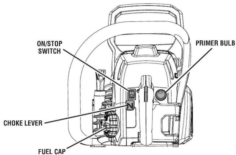
ON/STOP SWITCH PRIMER BULB CHOKE LEVER FUEL CAPFig. 1b
KNOW YOUR CHAIN SAW
See Figures 1a - 1b.
The safe use of this product requires an understanding of the information on the product and in this operator's manual as well as a knowledge of the project you are attempting. Before use of this product, familiarize yourself with all operating features and safety rules.
CHOKE LEVER
The choke lever opens and closes the choke valve in the carburetor. Positions available include FULL CHOKE and RUN.
FRONT HAND GUARD / CHAIN BRAKE
The chain brake is designed to quickly stop the chain from rotating. When the front hand guard/chain brake is pushed toward the bar, the chain should stop immediately. The chain brake does not prevent kickback.
GUIDE BAR
The factory-equipped guide bar has a small radius tip that offers a somewhat lower kickback potential.
The low kickback saw chain helps minimize the force of a kickback reaction by preventing the cutters from digging in too deeply at the kickback zone.
PRIMER BULB
The primer bulb pumps fuel from the fuel tank to the car buretor.
SAFE-T-TIP® ANTI-KICKBACK NOSE GUARD
The SAFE-T-TIP® Anti-Kickback Nose Guard is an attachment provided on the end of the guide bar to prevent the chain on the end of the guide bar from contacting the wood.
THROTTLE TRIGGER
The throttle trigger is used for controlling chain rotation.
ASSEMBLY
UNPACKING
This product has been shipped completely assembled.
- Carefully remove the product and any accessories from the box. Make sure that all items listed in the packing list are included.

WARNING:
Do not use this product if it is not completely assembled or if any parts appear to be missing or damaged. Use of a product that is not properly and completely assembled could result in serious personal injury.
■ Inspect the product carefully to make sure no breakage or damage occurred during shipping.
■ Do not discard the packing material until you have carefully inspected and satisfactorily operated the product.
■ If any parts are damaged or missing, please call 1-800-242-4672 for assistance.
PACKING LIST
Chain Saw
Scabbard
Combination Wrench
2-Cycle Engine Lubricant
Bar and Chain Lubricant (UT10588 only)
18 in. Replacement Chain (UT10588 only)
Case (not included with the UT10548)
Operator's Manual

WARNING:
If any parts are damaged or missing do not operate this product until the parts are replaced. Use of this product with damaged or missing parts could result in serious personal injury.

WARNING:
Do not attempt to modify this product or create accessories not recommended for use with this product. Any such alteration or modification is misuse and could result in a hazardous condition leading to possible serious personal injury.
NOTE: The chain saw has been fully factory tested. It is normal to find some slight lubricant residue on the saw. Read and remove all hang tags and store with the Operator's Manual.
OPERATION

WARNING:
Do not allow familiarity with this product to make you careless. Remember that a careless fraction of a second is sufficient to inflict serious injury.

WARNING:
Muffler surfaces are very hot during and after operation of the chain saw; keep all body parts away from the muffler. Serious burns may occur if contact is made with the muffler.
OPERATION

WARNING:
Always wear eye protection with side shields marked to comply with ANSI Z87.1, along with hearing and head protection. Failure to do so could result in objects being thrown into your eyes and other possible serious injuries.

WARNING:
Do not use any attachments or accessories not recommended by the manufacturer of this product. The use of attachments or accessories not recommended can result in serious personal injury.

WARNING:
Operation of this equipment may create sparks that can start fires around dry vegetation. A spark arrestor may be required. The operator should contact local fire agencies for laws or regulations relating to fire prevention requirements.
APPLICATIONS
You may use this product for the purposes listed below:
■ Basic limbing, felling, and bucking
■ Removing buttress roots

WARNING:
Always shut off engine before fueling. Never add fuel to a machine with a running or hot engine. Move at least 30 ft. from refueling site before starting the engine. DO NOT SMOKE and stay away from open flames or sparks. Failure to safely handle fuel could result in serious personal injury.
FUEL AND REFUELING
HANDLING THE FUEL SAFELY

WARNING:
Check for fuel leaks. A leaking fuel cap is a fire hazard and must be replaced immediately. If you find any leaks, correct the problem before using the product. Failure to do so could result in a fire that could cause serious personal injury.
■ Always handle fuel with care; it is highly flammable.
■ Always refuel outdoors and do not inhale fuel vapors.
■ Do not let gasoline or lubricant come in contact with skin.
- Keep gasoline and lubricant away from the eyes. If gasoline or lubricant comes in contact with the eyes, wash them immediately with clean water. If irritation is still present, see a doctor immediately.
■ Clean up spilled fuel immediately.
Refer to Refueling in the Specific Safety Rules section of this manual for additional safety information.
OXYGENATED FUELS
DO NOT USE E85 FUEL. IT WILL VOID YOUR WARRANTY.
NOTE: Fuel system damage or performance problems resulting from the use of an oxygenated fuel containing more than the percentages of oxygenates stated below are not covered under warranty.
Ethanol. Gasoline containing up to 10% ethanol by volume (commonly referred to as E10) is acceptable. E85 is not.
OPERATION
MIXING THE FUEL
This product is powered by a 2-cycle engine and requires pre-mixing gasoline and 2-cycle lubricant. Pre-mix unleaded gasoline and 2-cycle engine lubricant in a clean container approved for gasoline. DO NOT mix quantities larger than usable in a 30-day period.
Recommended fuel: This engine is certified to operate on unleaded gasoline intended for automotive use.
NOTE: We recommend you use Homelite premium 2-cycle lubricant or an equivalent high-quality synthetic 2-cycle lubricant in this product. Mix at 2.6 oz. per gallon (US).
Do not use automotive lubricant or 2-cycle outboard lubricant.
HIGH QUALITY 2-CYCLE ENGINE LUBRICANT CASOLINE LUBRICANT

. (US) (3.8 liter) 2.6 oz. (76 ml)
FILLING THE FUEL TANK
See Figure 2.
■ Clean the surface around the fuel cap to prevent contamination.
■ Loosen the fuel cap slowly, by turning counterclockwise.
- Carefully pour the fuel mixture into the tank. Avoid spillage.
■ Prior to replacing the fuel cap, clean and inspect the gasket.
- Immediately replace the fuel cap and hand tighten, by turning clockwise. Wipe up any fuel spillage.
■ Move at least 30 ft. away from refueling area before starting the product.
NOTE: It is normal for the engine to emit smoke during and after the first use.

text_image
50:1 & LUBRICANT MIX Fig. 2OPERATION
ADDING BAR AND CHAIN LUBRICANT
See Figure 3.
Use HOMELITE Bar and Chain Lubricant. It is designed for chains and chain oilers, and is formulated to perform over a wide temperature range with no dilution required. Chain saw should use approximately one tank of lubricant per tank of fuel.
NOTE: Do not use dirty, used, or otherwise contaminated lubricants. Damage may occur to the oil pump, bar, or chain.
■ Carefully pour the bar and chain lubricant into the oil tank.
■ Fill the oil tank every time you fuel the engine.
Check the operating condition of the chain brake prior to each use.
■ Engage the chain brake by rotating your left hand around the front handle, allowing the back of your hand to push the chain brake lever/hand guard toward the bar while the chain is rotating rapidly. Be sure to maintain both hands on the saw handles at all times.
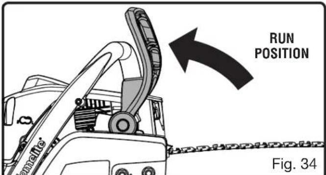
■ Reset the chain brake back into the RUN position by grasping the top of the chain brake lever/hand guard and pulling toward the front handle until you hear a click.

WARNING:
If the chain brake does not stop the chain immediately, or if the chain brake will not stay in the run position without assistance, take the saw to an authorized service center for repair prior to use.
STARTING THE ENGINE
See Figures 6 - 11.
Starting the product differs depending on whether the engine is cold or warm.

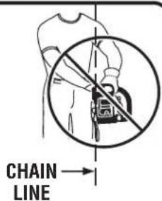
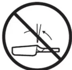
WARNING:
Keep your body to the left of the Never straddle the saw or chain, or lean over past the chain line.

text_image
LUNA JUSI SLIT MAYA Fig. 3
text_image
BRAKE POSITION Fig. 4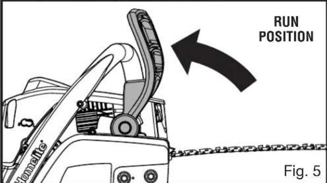
text_image
RUN POSITION Fig. 5
text_image
STARTER GRIP AND ROPE Fig. 6chain line.
OPERATION
■ Place the chain saw on level ground and ensure that no objects or obstructions are in the immediate vicinity that could come in contact with the bar and chain.
■ Hold the front handle firmly with your left hand and put your right foot onto the base of the rear handle.
To start a cold engine:
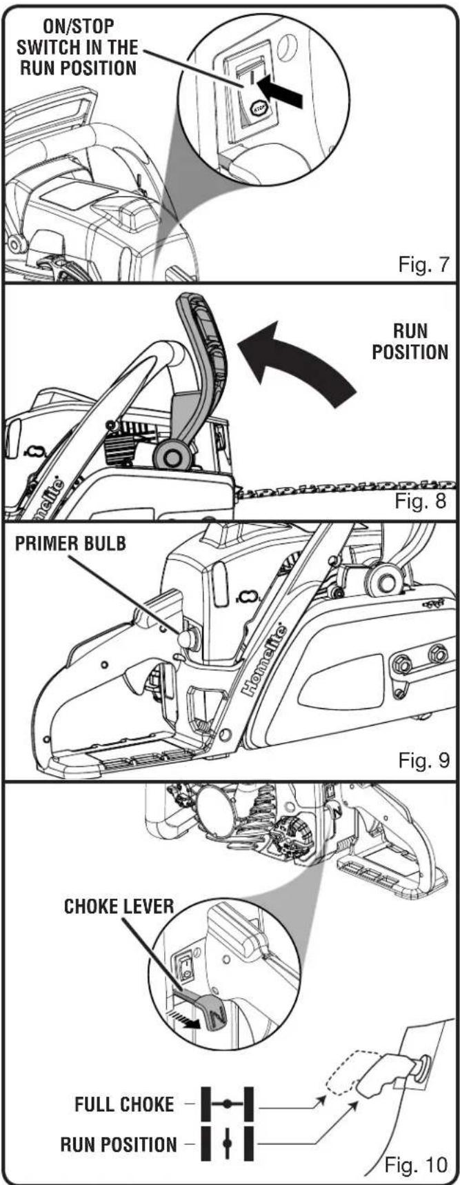
■ Set the on/stop switch to the RUN (1) position.
■ Make sure the chain brake is in the run position by pulling back on the lever/hand guard.
■ Fully press and release the primer bulb 7 times.
■ Pull choke lever all the way out to FULL position.
■ When the temperature is above 50^ F, pull the starter grip and rope until the engine attempts to start, but no more than 3 times. When the temperature is below 50^ F, pull the starter grip and rope until the engine attempts to start, but no more than 5 times.
■ Push choke lever to RUN position.
■ Pull starter grip and rope until engine runs.
NOTE: Allow the saw to run in this position 15-30 seconds, depending upon the temperature.
■ Depress the trigger release and squeeze and release the throttle trigger to return the engine to idle.
CAUTION:
Failure to release partial throttle when chain brake lever is in the brake position will result in serious damage to the unit. Never squeeze and hold the throttle trigger while the chain brake is in the brake position.
To start a warm engine:
■ Set the on/stop switch to the RUN (1) position.
■ Make sure the chain brake is in the run position by pulling back on the lever/hand guard.
■ Pull choke lever out to FULL CHOKE position then push immediately back to RUN position to set fast idle.
text_image
ON/STOP SWITCH IN THE RUN POSITION Fig. 7 RUN POSITION Primer Bulb Honneette Fig. 8 Fig. 9 CHOKE LEVER FULL CHOKE RUN POSITION Fig. 10OPERATION
■ Pull starter grip and rope until engine runs, but no more than 5 times. If engine does not start after 5 pulls, use cold engine starting procedure.
■ Squeeze and release the throttle trigger to return the engine to idle.
STOPPING THE ENGINE
See Figures 12 - 13.
Release the throttle trigger and let the engine return to idle. To stop the engine, move the on/stop switch to the STOP (position. Do not put the chain saw on the ground when the chain is still moving. For additional safety, set the chain brake when the saw is not in use.
In the event that the on/stop switch will not stop the saw, pull the choke lever out to the fully extended position (FULL CHOKE) and engage chain brake to stop the engine. If the on/stop switch will not stop the saw when set to the STOP position, have the on/stop switch repaired before using the chain saw again to prevent unsafe conditions or serious injury.
NOTE: When you are finished using the saw, always relieve tank pressure by loosening, then retightening, the chain oil and fuel caps. Allow the engine to cool before storing.
ADJUSTING IDLE SPEED
See Figure 14.

WARNING:
The chain will move around the guide bar when adjusting the idle speed. Wear all protective clothing and keep all bystanders, children, and pets at least 50 ft. away. Make adjustments with the unit supported on a stable surface so that the chain/guide bar does not contact the ground or any object. Keep all parts body away from the chain/guide bar and muffler. Failure to follow these instructions could result in serious personal injury.
If the engine starts, runs, and accelerates, but will not idle, turn the idle speed screw "T" clockwise to increase idle speed.

text_image
TRIGGER RELEASE THROTTLE TRIGGER Fig. 11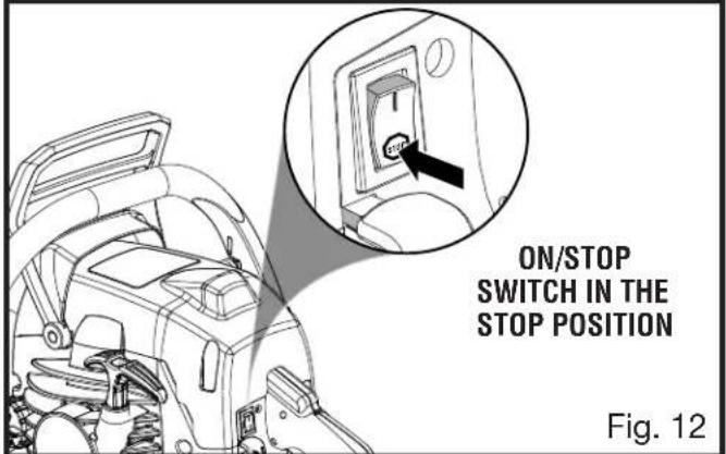
text_image
ON/STOP SWITCH IN THE STOP POSITION Fig. 12
text_image
BRAKE POSITION Fig. 13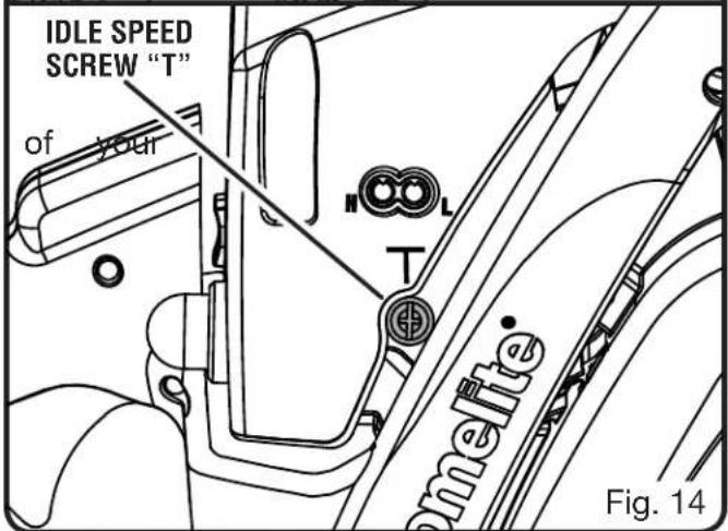
text_image
IDLE SPEED SCREW "T" of your N T lemette Fig. 14OPERATION
If the chain turns at idle, turn the idle speed screw "T" counterclockwise to reduce the idle RPM and stop the chain movement. If the saw chain still moves at idle speed, contact an authorized service center for adjustment and discontinue use until the repair is made.

WARNING:
THE SAW CHAIN SHOULD NEVER TURN AT IDLE. Turn the idle speed screw "T" counterclockwise to reduce the idle RPM and stop the chain, or contact an authorized service center for adjustment and discontinue use until the repair is made. Serious personal injury may result from the saw chain turning at idle.
PULL AND PUSH
See Figure 15.
The reaction force of the saw is always opposite to the direction the chain is moving. Thus, the operator must be ready to control the PULL when cutting on the bottom edge of the bar and the PUSH when cutting along the top edge.
NOTE: The chain saw has been fully factory tested. It is normal to find some slight oil residue on the saw.

text_image
PULL PUSH Fig. 15
WARNING:
KICKBACK occurs when the moving contacts an object at the upper portion of the tip of the guide bar or when the wood closes in and pinches the saw chain in the cut. Contact at the upper portion of the tip of the guide bar can cause the chain to dig into the object and stop the chain for an instant. The result is a lightning-fast reverse reaction which kicks the guide bar up and back toward the operator. If the saw chain is pinched along the top of the guide bar, the guide bar can be driven rapidly back toward the operator. Either of these reactions can cause loss of saw control, which can result in serious injury.
Do not rely exclusively upon the safety devices built into the saw. As a chain saw user, you should take steps to keep your cutting jobs free from accident or injury. See General Safety Rules for more details.
OPERATION
KICKBACK PRECAUTIONS
See Figures 16 - 17.
Rotational kickback occurs when the moving chain contacts an object at the Kickback Danger Zone of the guide bar. The result is a lightning-fast reverse reaction, which kicks the guide bar up and back towards the operator. This reaction can cause loss of control, which can result in serious injury.
PREPARING FOR CUTTING
PROPER GRIP ON HANDLES
See Figure 18.
See General Safety Rules for appropriate safety equipment.
■ Wear non-slip gloves for maximum grip and protection.
■ Hold the saw firmly with both hands. Always keep your left hand on the front handle and your right hand on the rear handle so that your body is to the left of the chain line.

WARNING:
Never use a left-handed (cross-handed) grip or any stance that would place your body or arm across the chain line.
- Maintain a proper grip on the saw whenever the engine is running. The fingers should encircle the handle and the thumb is wrapped under the handlebar. This grip is least likely to be broken by a kickback or other sudden reaction of the saw. Any grip in which the thumb and fingers are on the same side of the handle is dangerous because a slight kick of the saw can cause loss of control.

WARNING:
DO NOT operate the throttle trigger with your left hand and hold the front handle with your right hand. Never allow any part of your body to be in the chain line while operating a saw.
text_image
CHAIN LINE
text_image
KICKBACK DANGER ZONE Fig. 16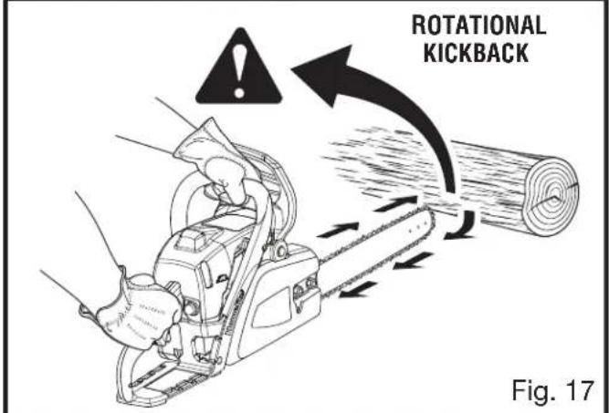
text_image
ROTATIONAL KICKBACK Fig. 17
text_image
PROPER HAND GRIP POSITION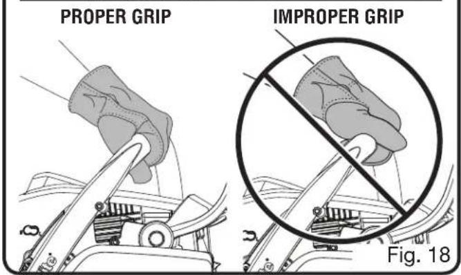
text_image
PROPER GRIP IMPROPER GRIP Fig. 18OPERATION
PROPER CUTTING STANCE
See Figure 19.

WARNING:
Always use the proper cutting stance described in this section. Never kneel when using the chain saw, except when felling a tree as illustrated in Figure 20. Kneeling could loss of stability and control of the chain saw, resulting in serious personal injury.
■ Balance your weight with both feet on solid ground.
- Keep left arm with elbow locked in a “straight arm” position to withstand any kickback force.
- Keep your body to the left of the chain line.
- Keep your thumb on underside of handlebar.
WORK AREA PRECAUTIONS
See Figure 20.
- Cut only wood or materials made from wood; no sheet metal, no plastics, no masonry, no non-wood building materials.
- Never allow children to operate the saw. Allow no person to use this chain saw who has not read this operator's manual or received adequate instructions for the safe and proper use of this chain saw.
- Keep everyone – helpers, bystanders, children, and animals, a SAFE DISTANCE from the cutting area. During felling operations, the safe distance should be a least twice the height of the largest trees in the felling area. During bucking operations, keep a minimum distance of 15 feet between workers.
■ Always cut with both feet on solid ground to prevent being pulled off balance.
■ Do not cut above chest height as a saw held higher is difficult to control against kickback forces.
■ Do not fell trees near electrical wires or buildings. Leave this operation for professionals. - Cut only when visibility and light are adequate for you to see clearly.

text_image
THUMB ON UNDERSIDEOF HANDLE BAR sult in CHAIN LINE STRAIGHT ARM Fig. 19
natural_image
Illustration of a worker using a tool near a tree with a prohibition symbol (no text or labels)BASIC OPERATING/CUTTING PROCEDURES
Practice cutting a few small logs using the following technique to get the “feel” of using the saw before you begin a major sawing operation.
■ Take the proper stance in front of the wood with the saw idling.
■ Accelerate the engine to full throttle just before entering the cut by squeezing the throttle trigger.
■ Begin cutting with the saw against the log.
- Keep the engine at full throttle the entire time you are cutting.
- Allow the chain to cut for you; exert only light downward pressure. Forcing the cut could result in damage to the bar, chain, or engine.
■ Release the throttle trigger as soon as the cut is completed allowing the engine to idle. Running the saw at full throttle without a cutting load can result in unnecessary wear to the chain, bar, and engine.
OPERATION
■ Do not put pressure on the saw at the end of the cut.
FELLING TREES
HAZARDOUS CONDITIONS

WARNING:
Do not fell trees during periods of high wind or heavy precipitation. Wait until the hazardous weather has ended.
When felling a tree, it is important that you heed the following warnings to prevent possible serious injury.
- Do not cut down trees having an extreme lean or large trees with rotten limbs, loose bark, or hollow trunks. Have these trees pushed or dragged down with heavy equipment, then cut them up.
■ Do not cut trees near electrical wires or buildings. - Check the tree for damaged or dead branches that could fall and hit you during felling.
■ Periodically glance at the top of the tree during the backcut to assure the tree is going to fall in the desired direction.
If the tree starts to fall in the wrong direction, or if the saw gets caught or hung up during the fall, leave the saw and save yourself!
PROPER PROCEDURE FOR TREE FELLING
See Figures 21 - 24.
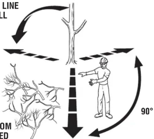
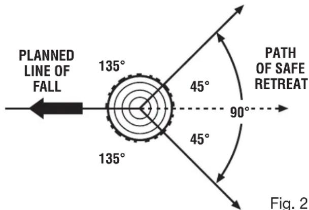
- Pick your escape route (or routes in case the intended route is blocked). Clear the immediate area around the tree and make sure there are no obstructions in your planned path of retreat. Clear the path of safe retreat approximately 135° from the planned line of fall.
- Consider the force and direction of the wind, the lean and balance of the tree, and the location of large limbs. These things influence the direction in which the tree will fall. Do not try to fell a tree along a line different from its natural line of fall.
- Cut a notch about 1/3 the diameter of the trunk in the side of the tree. Make the notch cuts so they intersect at a right angle to the line of fall.
PLANNED LINE OF FALL
flowchart
graph TD
    A["Tree"] -->|LINE LL| B["Downward arrow"]
    B --> C["Rightward arrow"]
    C --> D["90° Rotation"]
    D --> E["Human Figure"]
    style A fill:#f9f,stroke:#333
    style B fill:#ccf,stroke:#333
    style C fill:#cfc,stroke:#333
    style D fill:#fcc,stroke:#333
    style E fill:#ffc,stroke:#333
PATH OF SAFE RETREAT
text_image
PLANNED LINE OF FALL 135° 45° 90° PATH OF SAFE RETREAT 135° 45° Fig. 2Fig. 21

text_image
HINGE 2 in. OR 1/10 DIA NOTCH - APPROX. 1/3 DIAMETER OF TRUNK BACK CUT 2 in.Fig. 22
OPERATION
This notch should be cleaned out to leave a straight line. To keep the weight of the wood off the saw, always make the lower cut of the notch before the upper cut.
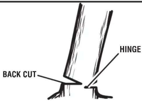
■ Make the backcut level and horizontal, and at a minimum of 2 in. above the horizontal cut of the notch.
NOTE: Never cut through to the notch. Always leave a band of wood between the notch and back cut (approximately 2 in. or 1/10 the diameter of the tree). This is called “hinge” or “hingewood.” It controls the fall of the tree and prevents slipping or twisting or shootback of the tree off the stump.
■ On large diameter trees, stop the back cut before it is deep enough for the tree to either fall or settle back on the stump. Then insert soft wooden or plastic wedges into the cut so they do not touch the chain. Drive wedges in, little by little, to help jack the tree over.
NOTE: When bucking or felling with a wedge, it may be necessary to remove the SAFE-T-TIP® anti-kickback device to allow the bar to be drawn through the cut. After you complete the cut, reinstall the tip immediately.
As tree starts to fall, stop the chain saw and put it down immediately. Retreat along the cleared path, but watch the action in case something falls your way.

WARNING:
Never cut through to the notch when making a back cut. The hinge controls the fall of the tree, this is the section of wood between the notch and backcut.
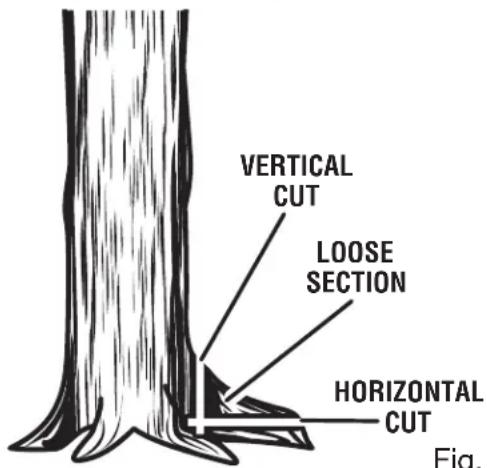
REMOVING BUTTRESS ROOTS
See Figure 25.
A buttress root is a large root extending from the trunk of the tree above the ground. Remove large buttress roots prior to felling. Make the horizontal cut into the buttress first, followed by the vertical cut. Remove the resulting loose section from the work area. Follow the correct tree felling procedure as stated in Proper Procedure For Tree Felling after you have removed the large buttress roots.
text_image
BACK CUT HINGEFig. 23

text_image
WEDGE Fig.Fig. 24
text_image
VERTICAL CUT LOOSE SECTION HORIZONTAL CUT Fig.Fig. 25
OPERATION
BUCKING
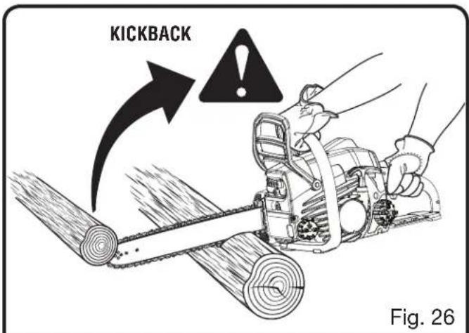
See Figure 26.
Bucking is the term used for cutting a fallen tree to the desired log length.
■ Cut only one log at a time.
■ Support small logs on a saw horse or another log while bucking.
- Keep a clear cutting area. Make sure that no objects can contact the guide bar nose and chain during cutting, this can cause kickback. To avoid the danger, keep the SAFE-T-TIP® anti-kickback device attached while cutting. Refer to Kickback in the Specific Safety Rules section of this manual for more information.
■ During bucking operations, stand on the uphill side so that the cut-off section of the log cannot roll over you.
■ Sometimes it is impossible to avoid pinching (with just standard cutting techniques) or difficult to predict which way a log will settle when cut.
BUCKING WITH A WEDGE
See Figure 27.
If the wood diameter is large enough for you to insert a soft bucking wedge without touching the chain, you should use the wedge to hold the cut open to prevent pinching.
NOTE: When bucking or felling with a wedge, you may need to remove the SAFE-T-TIP® anti-kickback device to allow the bar to be drawn through the cut. After you complete the cut, reinstall the tip.
text_image
KICKBACK Fig. 26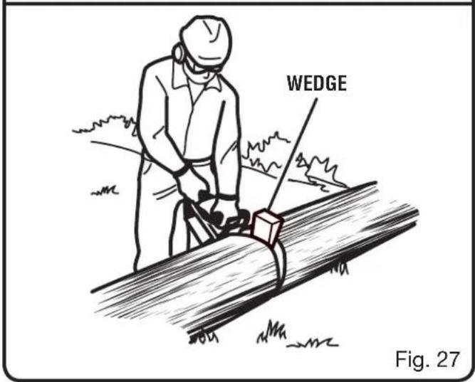
text_image
WEDGE Fig. 27OPERATION
BUCKING LOGS UNDER STRESS
See Figure 28.
Make the first bucking cut 1/3 of the way through the log and finish with a 2/3 cut on the opposite side. As you cut the log, it will tend to bend. The saw can become pinched or hung in the log if you make the first cut deeper than 1/3 of the diameter of the log.
Give special attention to logs under stress to prevent the bar and chain from pinching.
OVERBUCKING
See Figure 29.
Begin on the top side of the log with the bottom of the saw against the log; exert light pressure downward. Note that the saw will tend to pull away from you.
UNDERBUCKING
See Figure 30.
Begin on the under side of the log with the top of the saw against the log; exert light pressure upward. During underbucking, the saw will tend to push back at you. Be prepared for this reaction and hold the saw firmly to maintain control.
LOG SUPPORTED AT ONE END

text_image
FINISHING CUT LOAD 1ST CUT 1/3 DIALOG SUPPORTED AT BOTH ENDS

text_image
1ST CUT 1/3 DIA LOAD FINISHING CUT Fig. 28Fig. 28

text_image
OVERBUCKING Fig. 29Fig. 29

text_image
UNDERBUCKINGFig. 30
OPERATION
LIMBING AND PRUNING
See Figures 31 - 32.
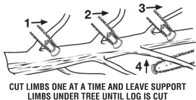
■ Work slowly, keeping both hands on the saw with a firm grip. Maintain secure footing and balance.
- Keep the tree between you and the chain while limbing.
■ Do not cut from a ladder. This is extremely dangerous. Leave this operation for professionals.
■ Do not cut above chest height. A saw held higher than chest height is difficult to control against kickback.

WARNING:
Never climb into a tree to limb or prune. Do not stand on ladders, platforms, rooftops, a log, or in any position which can cause you to lose your balance or control of the saw.
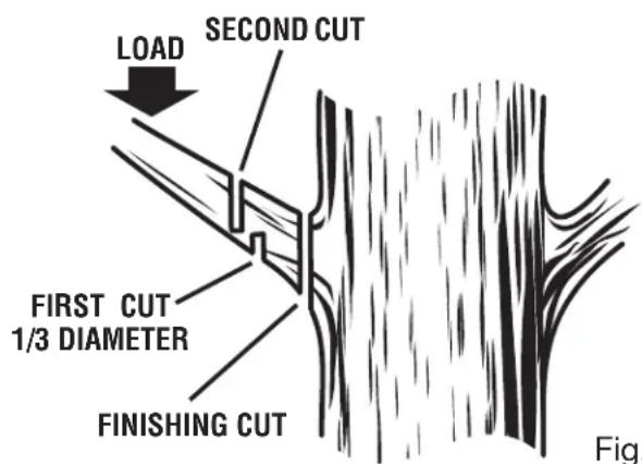
- When pruning trees it is important not to make the flush cut next to the main limb or trunk until you have cut off the limb further out to reduce the weight. This prevents stripping the bark from the main member.
- Underbuck the branch 1/3 through for your first cut.
• Overbuck the branch to drop it. - Finish by cutting smoothly and neatly against the main member so the bark will grow back to seal the wound.

WARNING:
If the limbs to be pruned are above chest height, hire a professional to perform the pruning.
CUTTING SPRINGPOLES
See Figure 33.
A springpole is any log, branch, rooted stump, or sapling which is bent under tension by other wood so that it springs back if the wood holding it is cut or removed. On a fallen tree, a rooted stump has a high potential of springing back to the upright position during the bucking cut to separate the log from the stump. Watch out for springpoles — they are dangerous.
text_image
LOAD SECOND CUT FIRST CUT 1/3 DIAMETER FINISHING CUT Fig.Fig. 31
text_image
1 2 3 4 CUT LIMBS ONE AT A TIME AND LEAVE SUPPORT LIMBS UNDER TREE UNTIL LOG IS CUTFig. 32

natural_image
Simple line drawing of a tree trunk with leaves and a small structure nearby (no text or symbols)SPRINGPOLE
Fig. 33

WARNING:
Springpoles are dangerous and could strike the operator, causing the operator to lose control of the chain saw. This could result in severe or fatal injury to the operator.
MAINTENANCE

WARNING:
Make sure the on/stop switch is in the STOP “ ” position and the chain has stopped before performing any maintenance on the saw. Failure to do so may result in serious personal injuries.

WARNING:
Muffler surfaces are very hot during and after operation of the chain saw; keep all body parts away from the muffler. Serious burns may occur if contact is made with the muffler.

WARNING:
When servicing, use only identical Homelite replacement parts. Use of any other parts may create a hazard or cause product damage.

WARNING:
Aways wear eye protection with side shields marked to comply with ANSI Z87.1, along with hearing and head protection. Failure to do so could result in objects being thrown into your eyes and other possible serious injuries.
GENERAL MAINTENANCE
Avoid using solvents when cleaning plastic parts. Most plastics are susceptible to damage from various types of commercial solvents and may be damaged by their use. Use clean cloths to remove dirt, dust, lubricant, grease, etc.

WARNING:
Do not at any time let brake fluids, gasoline, petroleum-based products, penetrating oils, etc., come in contact with plastic parts. Chemicals can damage, weaken or destroy plastic which may result in serious personal injury.
text_image
RUN POSITION Fig. 34
text_image
BAR MOUNTING NUTS COMBINATION WRENCH Fig. 35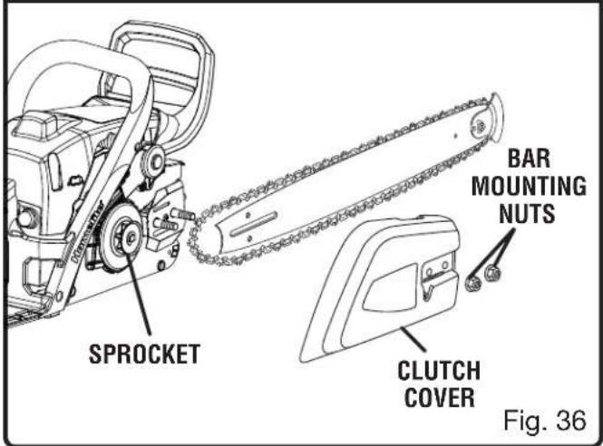
text_image
SPROCKET BAR MOUNTING NUTS CLUTCH COVER Fig. 36LUBRICATION
All of the bearings in this product are lubricated with a sufficient amount of high grade lubricant for the life of the unit under normal operating conditions. Therefore, no further lubrication is required.
MAINTENANCE
REPLACING THE GUIDE BAR AND CHAIN
See Figures 34 - 43.

DANGER:
Never start the engine before installing the guide bar, chain, clutch cover, and clutch drum. Without all these parts in place, the clutch can fly off or explode, exposing the user to possible serious injury.

WARNING:
To avoid serious personal injury, read and understand all the safety instructions in this section.
■ Always place the switch in the STOP "STAR" position before you work on the saw.
■ Make sure the chain brake is not set by pulling the chain brake lever/hand guard towards the front handle to the run position.
NOTE: When replacing the guide bar and chain, always use the specified bar and chain listed in the Bar and Chain Combinations section later in this manual.
■ Wear gloves when handling the chain and bar. These components are sharp and may contain burrs.
■ Remove the bar mounting nuts using the combination wrench provided.
■ Remove the clutch cover.
■ Remove the bar and chain from the mounting surface.
■ Remove the old chain from the bar.
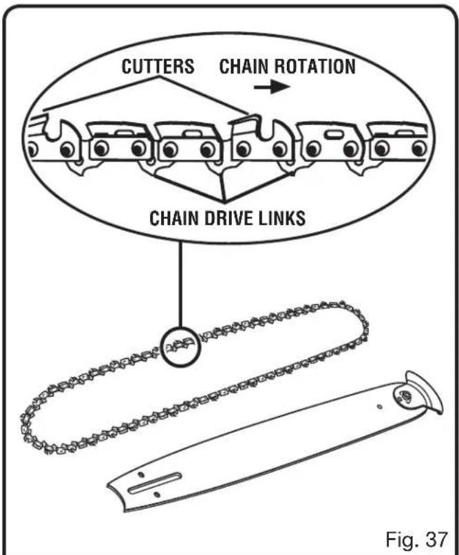
■ Lay out the new saw chain in a loop and straighten any kinks. The cutters should face in the direction of chain rotation. If they face backwards, turn the loop over.
■ Place the chain drive links into the bar groove as shown.
■ Position the chain so there is a loop at the back of the bar.
■ Hold the chain in position on the bar and place the loop around the sprocket.
text_image
CUTTERS CHAIN ROTATION CHAIN DRIVE LINKS Fig. 37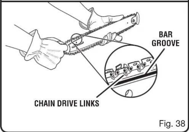
text_image
BAR GROOVE CHAIN DRIVE LINKS Fig. 38■ Fit the bar flush against the mounting surface so that the bar studs are in the long slot of the bar.
■ Replace the clutch cover ensuring that the adjusting pin in the clutch cover is in the bar chain tensioning pin hole and that both bar studs are securely in their respective holes in the clutch cover.
NOTE: The adjusting pin may need to be slightly repositioned with the chain tensioning screw
MAINTENANCE
so that it is aligned with the position of the bar chain tensioning pin hole.
■ Replace the clutch cover and bar mounting nuts.
■ Finger-tighten the bar mounting nuts. The bar must be free to move for tension adjustment.
■ Remove all slack from the chain by turning the chain tensioning screw clockwise until the chain seats snugly against the bar with the drive links in the bar groove.
■ Lift the tip of the guide bar up to check for sag.
■ Hold the tip of the guide bar up and tighten the bar mounting nuts securely.
The chain is correctly tensioned when there is no sag on the underside of the guide bar, the chain is snug, but it can be turned by hand without binding. Ensure that the chain brake is not set.
NOTE: If chain is too tight, it will not rotate. Loosen the bar nuts slightly and turn the tension adjuster 1/4 turn counterclockwise. Lift the tip of the guide bar up and retighten the bar nuts securely. Ensure that the chain will rotate without binding.

text_image
CLUTCH COVER ADJUSTING PIN CHAIN TENSIONING PIN HOLE SPROCKET CLUTCH COVER BAR MOUNTING NUTS Fig. 39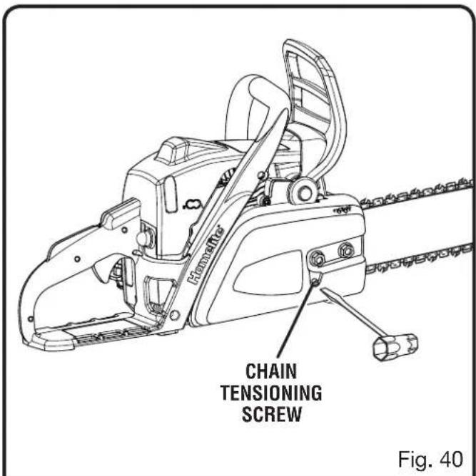
text_image
FlemmerGear CHAIN TENSIONING SCREW Fig. 40
text_image
GUIDE BAR Fig. 41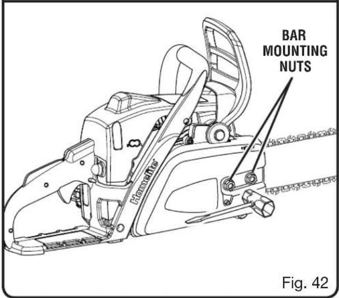
text_image
BAR MOUNTING NUTS Monette Fig. 42MAINTENANCE
ADJUSTING THE CHAIN TENSION
See Figures 44 - 46.

WARNING:
Never touch or adjust the chain while the engine is running. The saw chain is very sharp. Always wear protective gloves when performing maintenance on the chain.
■ Stop the engine before setting the chain tension.
■ Make sure the bar mounting nuts are loosened to finger tight.
■ Turn the chain tensioning screw clockwise to increase tension the chain.
NOTE: A cold chain is correctly tensioned when there is no slack on the underside of the guide bar, the chain is snug, and it can be turned by hand without binding.
■ Retension the chain whenever the flats on the drive links hang out of the bar groove.
NOTE: During normal saw operation, the temperature of the chain increases. The drive links of a correctly tensioned warm chain will hang approximately 0.050 in. out of the bar groove. The tip of the supplied combination wrench can be used as a guide to help determine the correct warm chain tension.
NOTE: New chains tend to stretch; check the chain tension frequently and tension as required.

CAUTION:
A chain tensioned while warm may be too tight upon cooling. Check the “cold tension” before next use to avoid possible injury.

MAINTENANCE
CHAIN MAINTENANCE
See Figures 47 - 48.

CAUTION:
Check that the switch is in the STOP "STOP" position before you work on the saw.
Use only a low-kickback chain on this saw. This fast-cutting chain provides kickback reduction when properly maintained.
For smooth and fast cutting, maintain the chain properly.
The chain requires sharpening when the wood chips are small and powdery, the chain must be forced through the wood during cutting, or the chain cuts to one side. During maintenance of the chain, consider the following:
■ Improper filing angle of the side plate can increase the risk of severe kickback.
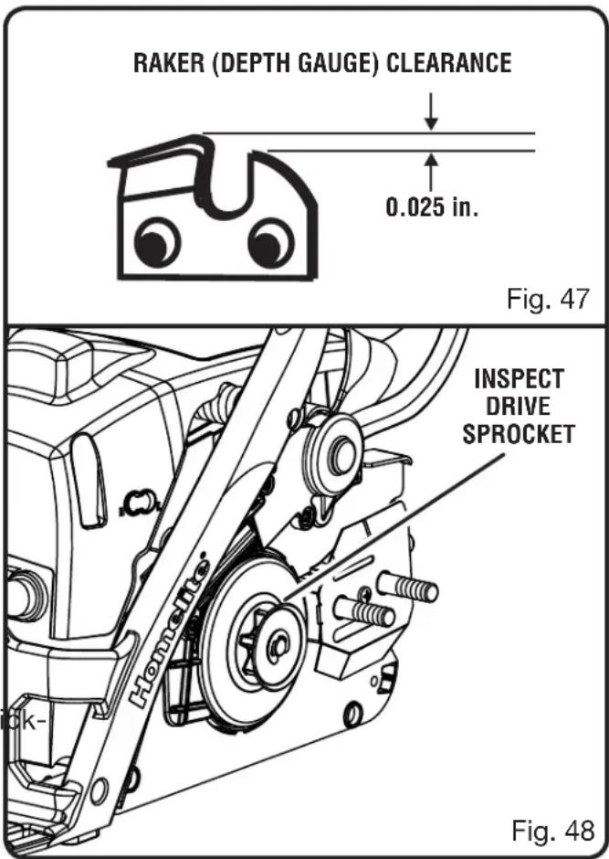
■ Raker (depth gauge) clearance.
- Too low increases the potential for back.
• Not low enough decreases cutting ability.
If the cutter teeth hit hard objects such as nails and stones, or are abraded by mud or sand on the wood, have an authorized service center sharpen the chain.
NOTE: Inspect the drive sprocket for wear or damage when replacing the chain. If signs of wear or damage are present in the areas indicated, have the drive sprocket replaced by an authorized service center.
NOTE: If you do not fully understand the correct procedure for sharpening the chain after reading the instructions that follow, have the saw chain sharpened by an authorized service center or replace with a recommended low-kickback chain.
text_image
RAKER (DEPTH GAUGE) CLEARANCE 0.025 in. Fig. 47 INSPECT DRIVE SPROCKET Homette Fig. 48MAINTENANCE
SHARPENING THE CUTTERS
See Figures 49 - 52.
Be careful to file all cutters to the specified angles and to the same length, as fast cutting can only be obtained when all cutters are uniform.

WARNING:
The saw chain is very sharp. Always wear protective gloves when performing maintenance to the chain to prevent serious personal injury.
■ Tension the chain prior to sharpening. Refer to Adjusting The Chain Tension.
■ Use a 5/32 in. diameter round file and holder. Do all of your filing at the midpoint of the bar.
- Keep the file level with the top plate of the tooth. Do not let the file dip or rock.
■ Using light but firm pressure. Stroke towards the front corner of the tooth.
■ Lift the file away from the steel on each return stroke.
- Put a few firm strokes on every tooth. File all left hand cutters in one direction. Then move to the other side and file the right hand cutters in the opposite direction.
■ Remove filings from the file with a wire brush.
CAUTION:
A dull or improperly sharpened chain can cause excessive engine speed during cutting, which may result in severe engine damage.

WARNING:
Improper chain sharpening increases the potential of kickback.

WARNING:
Failure to replace or repair a damaged chain can cause serious injury.

text_image
TOP PLATE RIVET HOLE HEEL GULLET CUTTING CORNER SIDE PLATE DEPTH GAUGE TOE Fig. 4Fig. 49

natural_image
Mechanical device with diagonal cutting tool and load applied, no visible text or symbolsFig. 50
natural_image
Diagram of a vehicle climbing a ramp with an upward arrow, no text or symbols presentFig. 51

text_image
LEFT HAND CUTTERS RIGHT HAND CUTTERSFig. 52
MAINTENANCE
TOP PLATE FILING ANGLE
See Figure 53.
■ CORRECT 30° – file holders are marked with guide marks to align file properly to produce correct top plate angle.
■ LESS THAN 30° – for cross cutting.
■ MORE THAN 30^ – feathered edge dulls quickly.
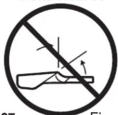
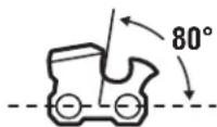
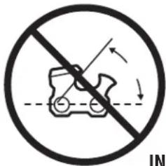
SIDE PLATE ANGLE
See Figure 54.
■ CORRECT 80° – Produced automatically if you use the correct diameter file in the file holder.
■ HOOK – “Grabs” and dulls quickly; increases the potential of KICKBACK. Results from using a file with a diameter too small or a file held too low.
■ BACKWARD SLOPE – Needs too much feed
TOP PLATE FILING ANGLE

CORRECT
LESS THAN 30°
natural_image
Prohibition sign showing a crossed-out tool without any text or symbolsMORE THAN 30°
text_image
CT FigINCORRECT
Fig. 53
SIDE PLATE FILING ANGLE
CORRECT
HOOK
text_image
Prohibition sign with a diagonal line crossing a vehicle silhouette, indicating no change or restriction.BACKWARD SLOPE

text_image
ECT FigFig. 54
pressure; causes excessive wear to the bar and chain. Results from using a file with a diameter too large or file held too high.
MAINTAINING DEPTH GAUGE CLEARANCE
See Figure 55 - 57.
- Maintain the depth gauge at a clearance of 0.025 in. Use a depth gauge tool for checking the depth gauge clearances.
■ Every time the chain is filed, check the depth gauge clearance.
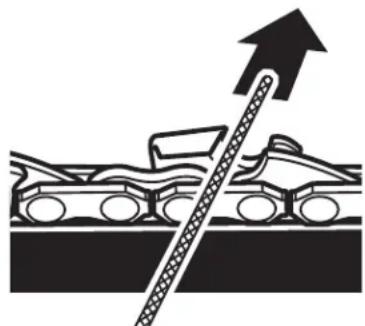
■ Use a flat file and a depth gauge jointer to lower all gauges uniformly. Use a 0.025 in. depth gauge jointer. After lowering each depth gauge, restore original shape by rounding the front. Be careful not to damage adjoining drive links with the edge of the file.
■ Depth gauges must be adjusted with the flat file in the same direction the adjoining cutter was filed with the round file. Use care not to contact cutter face with flat file when adjusting depth gauges.
RAKER (DEPTH GAUGE) CLEARANCE

text_image
0.025 in. FigFig. 55
DEPTH GAUGE JOINTER

text_image
DEPA AND BOCOMEN FLAT FILEFig. 56

flowchart
graph TD
    A["Step 1"] --> B{Decision}
    B --> C["Step 2"]
RESTORE ORIGINAL SHAPE BY ROUNDING THE FRONT
Fig. 57
MAINTENANCE
MAINTAINING THE GUIDE BAR
See Figure 58.

CAUTION:
Make sure the chain has stopped before you do any work on the saw.
Every week of use, reverse the guide bar on the saw to distribute the wear for maximum bar life. The bar should be cleaned every day of use and checked for wear and damage.
Feathering or burring of the bar rails is a normal process of bar wear. Such faults should be smoothed with a file as soon as they occur.
A bar with any of the following faults should be replaced:
■ Wear inside the bar rails that permits the chain to lay over sideways
■ Bent guide bar
■ Cracked or broken rails
- Spread rails
Lubricate guide bars with a sprocket at their tip weekly. Using a grease syringe, lubricate weekly in the lubricating hole. Turn the guide bar and check that the lubrication holes and chain groove are free from impurities.
MOUNTING THE SAFE-T-TIP® NOSE GUARD
See Figures 59 - 60.
■ Stop the engine and disconnect the spark plug wire.
■ Mount the SAFE-T-TIP on the bar nose.
■ Fit the locking tab in the recessed slot in the guide bar.
■ Tighten the mounting screw with wrench until snug.
■ From the snug position, tighten the mounting screw an additional 3/4 of a turn using a wrench.

MAINTAINING THE SAFE-T-TIP® NOSE GUARD
See Figures 59 - 60.

CAUTION:
Make sure the chain has stopped before you do any work on the saw.

WARNING:
Although the guide bar comes with a SAFET-TIP® antikickback device already installed, check the tightness of the mounting screw before each use.
MAINTENANCE
Use the following instructions to tighten the mounting screw of the nose guard. These are specially hardened screws. If you cannot install the screw tightly, replace both the screw and the SAFE-T-TIP® before further operation.
NOTE: Do not replace the screw with an ordinary screw. Use only identical replacement parts from the manufacturer when replacing parts.
In addition to preventing chain contact with solid objects at the nose of the bar, the SAFE-T-TIP ^® also helps keep the chain away from abrasive surfaces, such as the ground. Keep it on the right hand side of the bar where it will be between the chain and the ground during flush with ground cutting.
The mounting screw requires a 5/16 in. wrench (or adjustable wrench) to achieve the recommended torque of 35 to 45 in. lb. A torque within this range can be achieved by using the following method.
■ Tighten the screw with wrench until snug.
■ From the snug position, tighten the screw an additional 3/4 of a turn using a wrench.
CLEANING THE AIR FILTER
See Figures 61 - 62.
■ Activate the chain brake.
■ Remove the two screws holding the cylinder cover.
■ Lift the front of the cylinder cover past chain brake lever.
■ Lift the back of the cylinder cover past the handle.
■ Before removing the air filter from the carburetor, blow or brush as much loose dirt and sawdust from around the carburetor and chamber as possible.
NOTE: Make sure to pull the choke rod out to keep the carburetor from being contaminated.
■ Lift the air filter off the air filter base.
Choose one of the following cleaning options:
■ To lightly clean, tap the filter against a smooth, flat surface to dislodge most saw dust and dirt particles.

text_image
CYLINDER COVER SCREWS Fig. 61 AIR FILTER Fig. 62■ After every 5 hours of operation, clean in warm soapy water, rinse, and let dry completely. Replace with a new filter after every 25 hours of use.
NOTE: An alternate method is to clean the filter with compressed air. Always wear eye protection to avoid eye injury.
■ Reinstall the air filter.
NOTE: If you use an air hose for drying, blow through both side of filter.
CAUTION:
Make sure the air filter is correctly replaced before reassembly. Never run the engine without the air filter, as this may cause serious damage to the chain saw.
MAINTENANCE
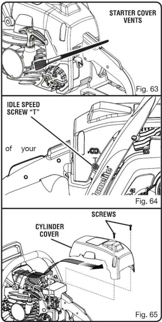
CLEANING THE STARTER UNIT
See Figure 63.
Use a brush or compressed air to keep the cooling vents of the starter assembly free and clean of debris.
ADJUSTING THE CARBURETOR
See Figure 64.

WARNING:
The chain will move around the guide bar when adjusting the idle speed. Wear all protective clothing and keep all bystanders, children, and pets at least 50 ft. away. Make adjustments with the unit supported on a stable surface so that the chain/guide bar does not contact the ground or any object. Keep all parts body away from the chain/guide bar and muffler. Failure to follow these instructions could result in serious personal injury.
Before adjusting the carburetor:
■ Use a brush or compressed air to clean the starter cover vents.
■ Clean the air filter. Refer to Cleaning the Air Filter in the Maintenance section of this manual.
- Allow the engine to warm up prior to adjustment of engine idle speed.

WARNING:
Weather conditions and altitude may affect carburetion. Do not allow bystanders close to the chain saw while adjusting the carburetor.
Idle Speed Adjustment — The idle speed adjustment controls how much the throttle valve stays open when the throttle trigger is released. To adjust:
■ Turn idle speed screw "T" clockwise to increase idle speed.
■ Turn idle speed screw "T" counterclockwise to decrease idle speed.

WARNING:
THE SAW CHAIN SHOULD NEVER TURN AT IDLE. Serious personal injury may result from the saw chain turning at idle.
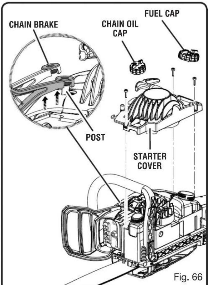
MAINTENANCE
CLEANING THE ENGINE
See Figures 65 - 68.
Clean the cylinder fins and flywheel fins with compressed air or a brush periodically. Dangerous overheating of the engine may occur due to impurities on the cylinder.

WARNING
Never run the saw without all the parts, including the clutch cover and starter housing, securely in place.
Because parts can fracture and pose a danger of thrown objects, leave repairs of the flywheel and clutch to factory trained authorized service center personnel.
■ Remove the screws and cylinder cover as described previously.
■ Clean the cylinder fins.
■ Lift the chain brake over the post.
■ Lay the chain saw on its side with the bar and chain on the ground.
■ Remove the chain oil and fuel caps.
■ Remove the three screws that hold the starter housing in place.
■ Lift off the starter cover and set aside.
■ Replace chain oil and fuel caps to prevent contamination during cleaning.
■ Clean the flywheel fins.
■ Remove the chain oil and fuel caps.
■ Replace the starter housing. Reinstall screws and secure.
■ Replace the chain oil and fuel caps.
■ Replace the cylinder cover. Reinstall screws and secure.
■ Replace the chain brake on the post.
NOTE: Check to ensure that the air filter is in the proper position before reinstalling the cylinder cover.
NOTE: If you notice a power loss with the gas-powered tool, the exhaust port and muffler may be blocked with carbon deposits. These deposits may need to be removed to restore performance. We highly recommend that only qualified service technicians perform this service.
text_image
CHAIN BRAKE POST CHAIN OIL CAP FUEL CAP STARTER COVER Fig. 66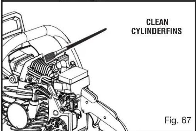
text_image
CLEAN CYLINDERFINS Fig. 67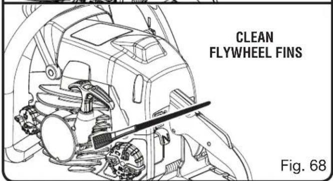
text_image
CLEAN FLYWHEEL FINS Fig. 68MAINTENANCE
CHECKING THE FUEL FILTER
See Figure 69.
Check the fuel filter periodically. If contaminated or damaged, have fuel filter replaced by an authorized service center.
REPLACING THE SPARK PLUG
See Figure 70.
This engine uses a Champion RCJ-6Y with 0.025 in. electrode gap. Use an exact replacement and replace every 50 hours or more frequently, if necessary.
■ Loosen the spark plug by turning it counterclockwise with a wrench.
■ Remove the spark plug.
■ Hand thread the new spark plug, turning it clockwise. Tighten securely with wrench.
NOTE: Be careful not to cross-thread the spark plug. Cross-threading will seriously damage the cylinder.
CLEANING THE EXHAUST PORT, MUFFLER, AND SPARK ARRESTOR
NOTE: Depending on the type of fuel used, the type and amount of lubricant used, and/or your operating conditions, the exhaust port, muffler, and/or spark arrestor screen may become blocked with carbon deposits. If you notice a power loss with your gas powered tool, you may need to remove these deposits to restore performance. We highly recommend that only qualified service technicians perform this service.
The spark arrestor must be cleaned or replaced every 50 hours or yearly to ensure proper performance of your product. Spark arrestors may be in different locations depending on the model purchased. Please contact your nearest service dealer for the location of the spark arrestor for your model.

WARNING:
To avoid a fire hazard, never run the chain saw without the spark arrestor in place.

text_image
FUEL FILTER Fig. 69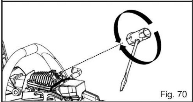
natural_image
Diagram showing mechanical assembly with a hammer and gear, no text or symbols present
text_image
CLEAN THE CHAIN BRAKE Honneette Fig. 71INSPECTING AND CLEANING CHAIN BRAKE
See Figure 71.
■ Always keep the chain brake mechanism clean and lightly brush the linkage.
■ Always test the chain brake performance after cleaning. Refer to Operating Chain Brake for additional information.
MAINTENANCE
WARNING:
Even with daily cleaning of the mechanism, the dependability of a chain brake to perform under field conditions cannot be certified. Keep the SAFE-T-TIP® nose guard on the saw's guide bar and use proper cutting techniques.
STORING THE PRODUCT
■ Clean all foreign material from the product. Store it in a well-ventilated place that is inaccessible to children. Keep away from corrosive agents such as garden chemicals and de-icing salts.
■ Abide by all Federal and local regulations for the safe storage and handling of gasoline.
When storing 1 month or longer:
- Drain all fuel from tank into a container approved for gasoline.
■ Run the engine until it stops. This will remove all fuel-lubricant mix that could become stale and leave varnish and gum in the fuel system.
■ Squeeze primer bulb several times to purge fuel from carburetor.
- Drain all bar and chain lubricant from tank into a container approved for oil.
■ Always place the scabbard over the guide bar and chain before transporting or storing the unit.
Please have an authorized service center adjust this engine if it is to be run above 2000 feet. Failure to do so may result in poor engine performance and increased emissions. An engine adjusted for high altitudes can not be run at 2000 feet or lower. In doing so, the engine will overheat and cause serious engine damage. Please have an authorized service center restore high altitude modified engines to the original factory specification before operating below 2000 feet.
EMISSIONS MAINTENANCE SCHEDULE AND WARRANTED PARTS LIST
| Emissions Parts Inspect Clean Before Every Every 25 Hours Each Use | Replace Clean Every Replace 25 Hours 5 Hours | Every or Yearly | or Yearly | 50 Hours |
AIR FILTER ASSY
includes:
Filter ....X....X
CARBURETOR ASSY
includes:
Heat Dam
Gaskets
FUEL TANK ASSY
includes:
Fuel Lines....X
Fuel Cap....X
Fuel Filter
IGNITION ASSY
includes:
Spark Plug....X
ALL EMISSIONS-RELATED PARTS ARE WARRANTED FOR TWO YEARS OR FOR THE PERIOD OF TIME PRIOR TO THE PARTS FIRST SCHEDULED REPLACEMENT WHICH EVER COMES FIRST.
BAR AND CHAIN COMBINATIONS
Chain specifications: 3/8 in. pitch, .05 in. chain gauge
Length of Bar Guide Bar Part Number Chain Part Number Drive Links
14 in. 310625001 901212001 52
16 in. 310626001 901212002 56
18 in. 310627001 671258001 62
TROUBLESHOOTING
| Problem Possible Cause Solution | ||
| Engine will not start. [Make sure on/stop switch is in the RUN (I) position.] | No spark.Engine is flooded. | Clean or replace spark plug. Reset spark plug gap. Refer to Spark Plug Replacement earlier in this manual.With the on/stop switch OFF, remove spark plug. Move choke lever to RUN position (pushed in completely) and pull starter cord 15 to 20 times. This will clear excess fuel from engine. Clean and reinstall spark plug. Set on/stop switch to RUN (I) position. Push and fully release primer bulb 7 times. Pull starter three times with choke lever at RUN. If engine does not start, move choke lever to FULL CHOKE and repeat normal starting procedure. If engine still fails to start, repeat procedure with a new spark plug. |
| Engine starts but will not accelerate properly. | Carburetor requires “L” (Low Jet) adjustment. | Contact an authorized service center for carburetor adjustment. |
| Engine starts, then dies. | Carburetor requires “L” (Low Jet) adjustment. | Contact an authorized service center for carburetor adjustment. |
| Engine starts but will not run properly at high speed. | Carburetor requires “H” (High Jet) adjustment. | Contact an authorized service center for carburetor adjustment. |
| Engine does not reach full speed and/or emits excessive smoke. | Lubricant/fuel mixture incorrect.Air filter is dirty.Carburetor requires “H” (High Jet) adjustment. | Use fresh fuel and the correct 2-cycle lubricant mix ratio.Clean air filter. Refer to Cleaning the Air Filter in the Maintenance section of this manual.Contact an authorized service center for carburetor adjustment. |
TROUBLESHOOTING
| Problem Possible Cause Solution | ||
| Engine starts, runs, and accelerates but will not idle. | Carburetor requires adjustment to idle speed. | Turn idle speed screw “T” clockwise to increase idle speed. Refer toAdjusting the Carburetorin the Maintenancesection of this manual. |
| Chain turns at idle. | Carburetor requires adjustment to idle speed.Air leak in the intake system. | Turn idle speed screw “T” counterclockwise to decrease speed. Refer toAdjusting the Carburetorin theMaintenancesection of this manual.Contact an authorized service center for a rebuild kit. |
| Bar and chain running hot and smoking. | Chain oil tank empty. | Oil tank should be filled every time fuel tank is filled. |
| Chain tension is too tight. | Tension chain per instructions inAdjusting the Chain Tensionin theMaintenancesection of this manual. | |
| Oiler is not functioning. | Run at half throttle 30 to 45 seconds. Stop saw and check for lubricant dripping from SAFE-T-TIP®and guide bar. If lubricant is present, the chain may be dull or bar may be damaged. If no lubricant is on the SAFE-T-TIP®, contact an authorized service center. | |
| Engine starts and runs, but chain is not rotating. | Chain brake is engaged. | Release chain brake. Refer toOperating the Chain Brakein theOperationsection of this manual. |
| Chain tension is too tight. | Tension chain per instructions inAdjusting the Chain Tensionin theMaintenancesection of this manual. | |
| Guide bar and chainassembled incorrectly. | Refer toReplacing the Guide Bar and Chainin the Maintenancesection of this manual. | |
| Guide bar and/or chain are damaged. | Inspect guide bar and chain for damage. | |
| Drive sprocket teeth damaged | Contact an authorized service center for drive sprocket replacement. | |

text_image
NEED HELP ? CALL 1-800-242-4672 www.homelite.comCALL US FIRST
For any questions about operating or maintaining your product, call the Homelite® Help Line!
Your product has been fully tested prior to shipment to ensure your complete satisfaction.
WARRANTY
LIMITED WARRANTY STATEMENT
Homelite Consumer Products, Inc., (“Homelite”) warrants to the original retail purchaser that this HOMELITE brand outdoor product is free from defect in material and workmanship and agrees to repair or replace, at Homelite’s, discretion, any defective product free of charge within these time periods from the date of purchase.
■ Two years if the product is used for personal, family or household use;
■ 90 days for any unit used for other purposes, such as rental or commercial.
This warranty extends to the original retail purchaser only and commences on the date of the original retail purchase.
Any part of the this product manufactured or supplied by Homelite and found in the reasonable judgment of Homelite to be defective in material or workmanship will be repaired or replaced without charge for parts and labor by a Homelite authorized service center.
The product, including any defective part, must be returned to an authorized service dealer within the warranty period. The expense of delivering the product to the dealer for warranty work and the expense of returning it back to the owner after repair or replacement will be paid by the owner. Homelite's responsibility in respect to claims is limited to making the required repairs or replacements and no claim of breach of warranty shall be cause for cancellation or rescission of the contract of sale of any HOMELITE brand product. Proof of purchase will be required by the dealer to substantiate any warranty claim. All warranty work must be performed by a Homelite authorized service center.
This warranty is limited to ninety (90) days from the date of original retail purchase for any HOMELITE brand product that is used for rental or commercial purposes, or any other income-producing purpose.
This warranty does not cover any HOMELITE brand product that has been subject to misuse, neglect, negligence, or accident, or that has been operated in any way contrary to the operating instructions as specified in this operator's manual. This warranty does not apply to any damage to the product that is the result of improper maintenance or to any product that has been altered or modified. The warranty does not extend to repairs made necessary by normal wear or by the use of parts or accessories which are either incompatible with the HOMELITE brand product or adversely affect its operation, performance, or durability. In addition, this warranty does not cover:
B. Wear items - Bump Knobs, Outer Spools, Lines, Inner Reels, Starter Pulleys, Starter Ropes, Drive Belts, Tines, Felt Washers, Hitch Pins, Mulching Blades, Blower Fans, Blower and Vacuum Tubes, Vacuum Bags and Straps, Guide Bars, Saw Chains, Blades
Homelite reserves the right to change or improve the design of any HOMELITE brand product without assuming any obligation to modify any product previously manufactured.
ALL IMPLIED WARRANTIES ARE LIMITED IN DURATION TO THE STATED WARRANTY PERIOD. ACCORDINGLY, ANY SUCH IMPLIED WARRANTIES INCLUDING MERCHANTABILITY, FITNESS FOR A PARTICULAR PURPOSE, OR OTHERWISE, ARE DISCLAIMED IN THEIR ENTIRETY AFTER THE EXPIRATION OF THE APPROPRIATE TWO-YEAR OR NINETY-DAY WARRANTY PERIOD. HOMELITE'S OBLIGATION UNDER THIS WARRANTY IS STRICTLY AND EXCLUSIVELY LIMITED TO THE REPAIR OR REPLACEMENT OF DEFECTIVE PARTS AND HOMELITE DOES NOT ASSUME OR AUTHORIZE ANYONE TO ASSUME FOR THEM ANY OTHER OBLIGATION. SOME STATES DO NOT ALLOW LIMITATIONS ON HOW LONG AN IMPLIED WARRANTY LASTS, SO THE ABOVE LIMITATION MAY NOT APPLY TO YOU. HOMELITE ASSUMES NO RESPONSIBILITY FOR INCIDENTAL, CONSEQUENTIAL, OR OTHER DAMAGES INCLUDING, BUT NOT LIMITED TO, EXPENSE OF RETURNING THE PRODUCT TO AN AUTHORIZED HOMELITE SERVICE CENTER AND EXPENSE OF DELIVERING IT BACK TO THE OWNER, MECHANIC'S TRAVEL TIME, TELEPHONE OR TELEGRAM CHARGES, RENTAL OF A LIKE PRODUCT DURING THE WARRANTY SERVICE IS BEING PERFORMED, TRAVEL, LOSS OR DAMAGE TO PERSONAL PROPERTY, LOSS OF REVENUE, LOSS OF USE OF THE PRODUCT, LOSS OF TIME, OR INCONVENIENCE. SOME STATES DO NOT ALLOW THE EXCLUSION OR LIMITATION OF INCIDENTAL OR CONSEQUENTIAL DAMAGES, SO THE ABOVE LIMITATION OR EXCLUSION MAY NOT APPLY TO YOU.
This warranty gives you specific legal rights, and you may also have other rights which vary from state to state.
This warranty applies to all HOMELITE brand products manufactured by or for Homelite and sold in the United States and Canada.
To locate your nearest Homelite authorized service center, dial 1-800-242-4672 or log on to our website at www.homelite.com.
A. Tune-ups - Spark Plugs, Carburetor, Carburetor
Adjustments, Ignition, Filters
WARRANTY
THE FOLLOWING CALIFORNIA AIR RESOURCES BOARD (CARB) STATEMENT ONLY APPLIES TO MODEL NUMBERS REQUIRED TO MEET THE CARB REQUIREMENTS.
HOMELITE CONSUMER PRODUCTS, INC., LIMITED WARRANTY STATEMENT FOR FEDERAL AND CALIFORNIA EMISSION CONTROL SYSTEMS NON-ROAD AND SMALL OFF-ROAD ENGINES
YOUR WARRANTY RIGHTS AND OBLIGATIONS
The U.S. Environmental Protection Agency (EPA), the California Air Resources Board (CARB), and Homelite Consumer Products, Inc., are pleased to explain the Emissions Control System Warranty on your non-road or small off-road engine. In California, new equipment that uses small off-road engines must be designed, built, and equipped to meet the state's stringent anti-smog standards. In other states, new 2011 and later model year non-road engines must be designed, built, and equipped at the time of sale to meet the U.S. EPA regulations for small non-road engines. The non-road engine must be free from defects in materials and workmanship which cause it to fail to conform with U.S. EPA standards for the first two years of engine use from the date of sale to the ultimate purchaser. Homelite Consumer Products, Inc., must warrant the emission control system on your non-road or small off-road engine for the period of time listed above provided there has been no abuse, neglect, or improper maintenance of your non-road or small off-road engine.
Your emission control system may include parts such as the carburetor or fuel injection system, the ignition system, catalytic converters, fuel tanks, valves, filters, clamps, connectors, and other associated components. Also included may be hoses, belts and connectors, and other emission-related assemblies.
Where a warrantable condition exists, Homelite Consumer Products, Inc., will repair your non-road or small off-road engine at no cost to you, including diagnosis, parts, and labor performed at an authorized service center for HOMELITE® brand outdoor products.
MANUFACTURER'S WARRANTY COVERAGE:
This product's emissions control system is warranted for two years. If any emission-related part on your engine is defective, the part will be repaired or replaced by Homelite Consumer Products, Inc., free of charge.
OWNER'S WARRANTY RESPONSIBILITIES
(a) As the non-road or small off-road engine owner, you are responsible for the performance of the required maintenance listed in your operator's manual. Homelite Consumer Products, Inc., recommends that you retain all receipts covering maintenance on your non-road or small off-road engine, but Homelite Consumer Products, Inc., cannot deny warranty solely for the lack of receipts or for your failure to ensure the performance of all scheduled maintenance. (b) As the non-road or small off-road engine owner, you should be aware, however, that Homelite Consumer Products, Inc., may deny you warranty coverage if your non-road or small off-road engine or a part has failed due to abuse, neglect, improper maintenance, or unapproved modifications.
(c) You are responsible for presenting your non-road or small off-road engine to an authorized service dealer as soon as a problem exists. The warranty repairs should be completed in a reasonable amount of time, not to exceed 30 days.
If you have any questions regarding your warranty rights and responsibilities, you should contact a Homelite Consumer Products, Inc., Customer Representative at 1-800-242-4672.
DEFECT WARRANTY COVERAGE REQUIREMENTS:
(a) The warranty period begins on the date the engine or equipment is delivered to an ultimate purchaser.
(b) General Emissions Warranty Coverage. Homelite Consumer Products, Inc., warrants to the ultimate purchaser and each subsequent purchaser that your non-road or small off-road engine is designed, built, and equipped at the time of sale to conform with all applicable regulations adopted by the California Air Resources Board or the United States Environmental Protection Agency; and that it is free from defects in materials and workmanship which cause the engine to fail to conform with applicable regulations for a period of two years from the date the non-road or small off-road engine is purchased by the initial purchaser. Any replacement part or service that is equivalent in performance and durability may be used in non-warranty maintenance or repairs, and shall not reduce the warranty obligations of Homelite Consumer Products, Inc.
(c) The warranty on emissions-related parts will be interpreted as follows: Any warranted part that is not scheduled for replacement as required in the Maintenance Schedule is warranted for two years. If any such part (including any part that is scheduled only for regular inspection) fails during the period of warranty coverage, it will be repaired or replaced at any HOMELITE ^10 Authorized Service Center at no charge. Any such part repaired or replaced under warranty will be warranted for the remaining warranty period. A statement to the effect of “repair or replace as necessary” would not reduce the period of warranty coverage. Any warranted part that is scheduled for replacement as required maintenance in the Maintenance Schedule
is warranted for the period of time prior to the first scheduled replacement point for that part. Any such part repaired or replaced under warranty is warranted for the remainder of the period prior to the first scheduled replacement point, and will be repaired or replaced at any HOMELITE ^25 Authorized Service Center for no charge until that replacement point is reached.
Homelite Consumer Products, Inc., shall remedy warranty defects at any authorized HOMELITE® Authorized Service Center, including any distribution center that may be franchised to service the subject engines. Any diagnostic work done at a HOMELITE® Authorized Service Center shall be free of charge to the owner if such work determines that a warranted part is defective. Any manufacturer-approved or equivalent replacement part may be used for any warranty maintenance or repairs on emission-related parts, and must be provided free of charge to the owner if the part is still under warranty. Homelite Consumer Products, Inc., is liable for damages to other engine components caused by the failure of a warranted part still under warranty.
Add-on or modified parts that are not exempted by the California Air Resource Board may not be used. The use of any non-exempted add-on or modified parts will be grounds for disallowing a warranty claim. Homelite Consumer Products, Inc., will not be liable to warrant failures of warranted parts caused by the use of a non-exempted add-on or modified part.
The Emission Parts List specifically defines the emission-related warranted parts. Homelite Consumer Products, Inc., will provide any documents that describe its warranty procedures or policies within five days upon request by the California Air Resources Board.
EMISSIONS PARTS LIST
Emissions parts vary from product to product. Your emissions control system warranty applies to any of the following components that may be included on your product:
(1) Fuel Metering System
(i) Carburetor and internal parts (and/or pressure regulator or fuel injection system).
(ii) Air/fuel ratio feedback and control system.
(iii) Cold start enrichment system.
(iv) Fuel Tank.
(2) Air Induction System
(i) Controlled hot air intake system.
(ii) Intake manifold.
(iii) Air filter.
(3) Ignition System
(i) Spark plugs.
(ii) Magneto or electronic ignition system.
(iii) Spark advance/retard system.
(4) Exhaust Gas Recirculation (EGR) System
(i) EGR valve body and carburetor spacer, if applicable.
(ii) EGR rate feedback and control system.
(5) Air Injection System
(i) Air pump or pulse valve.
(ii) Valves affecting distribution of flow.
(iii) Distribution manifold.
(6) Catalyst or Thermal Reactor System
(i) Catalytic converter.
(ii) Thermal reactor.
(iii) Exhaust manifold.
(7) Particulate Controls
(i) Traps, filters, precipitators, and any other device used to capture particulate emissions.
(8) Miscellaneous Items Used in Above Systems
(i) Electronic controls.
(ii) Vacuum, temperature, and time sensitive valves and switches.
(iii) Hoses, belts, connectors, and assemblies.
Homelite Consumer Products, Inc., will furnish with each new engine written instructions for its maintenance and use by the owner.
RÈGLES DE SÉCURITÉ GÉNÉRALES

AVERTISSEMENT :
APPROVISIONNEMENT EN CARBURANT (NE PAS FUMER!)
TENUE CORRECTE DES POIGNÉES
Voir la figure 18.
text_image
TENUE CORRECTE DES POIGNÉES
text_image
PRISE CORRECTE TENUE INCORRECTE Fig. 18UTILISATION

AVERTISSEMENT :
TRONÇONNAGE AVEC COINS
Voir la figure 27.
text_image
COIN Fig. 27UTILISATION
DÉBITAGE DE BILLES SOUS CONTRAINTE
Voir la figure 28.
natural_image
Illustration of a hand using a chainsaw to cut wood or metal (no text or symbols present)COUPE PAR LE DESSUS
Fig. 29
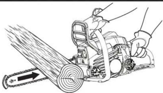
natural_image
Illustration of a manual power saw cutting through a chain (no text or symbols)COUPE PAR LE DESSOUS
Fig. 30
UTILISATION

AVERTISSEMENT :
natural_image
Diagram of a tree trunk with leaves and a small house, labeled 'FOUET' and 'Fig. 33' (no text or symbols on the diagram itself)ENTRETIEN

AVERTISSEMENT :
natural_image
Mechanical device with diagonal cutting tool and horizontal rod, showing motion direction (no text or symbols)Fig. 50

natural_image
Diagram of a vehicle climbing a track with an upward arrow indicating motion (no text or symbols)Fig. 51
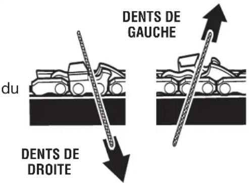
text_image
du DENTS DE DROITE DENTS DE GAUCHEFig. 52
accroît le
ENTRETIEN
ANGLE D'AFFÛTAGE DE LA PLAQUE SUPÉRIEURE
Voir la figure 53.
natural_image
Prohibition sign showing a crossed-out tool with motion lines, enclosed in a circle (no text or symbols)INCORRECT
PLUS DE 30°
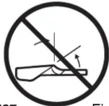
text_image
ST FiFig. 53
ANGLE D'AFFÛTAGE DE LA PLAQUE LATÉRALE

CORRECT
CROCHET
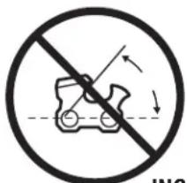
text_image
INCINCORRECT
ANGLE ARRIÈRE

text_image
FCTFig. 54
natural_image
Simple line drawing of a stylized car head with two eyes (no text or symbols)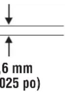
Fig. 55
COUPLEUR DE LIMITEUR DE PROFONDEUR

text_image
LIME PLATEFig. 56

flowchart
graph TD
    A["Robot icon"] --> B["R"]
    C["Robot icon"] --> B["R"]
RENDRE LA FORME
D'ORIGINE EN
ARRONDISSANT
L'AVANT
Fig. 57
ENTRETIEN
natural_image
Illustration of a person using a tool to cut a tree trunk, labeled 'CUÑA' and 'Fig.' (no other text or symbols)Fig. 24
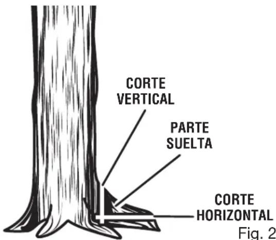
text_image
CORTE VERTICAL PARTE SUELTA CORTE HORIZONTAL Fig. 2Fig. 25

text_image
CONTRAGOLPE Fig. 26FUNCIONAMIENTO
TRONZADO CON CUÑA
Vea la figura 27.
natural_image
Illustration of a hand using a chain-link tool to cut a chain, with an arrow indicating the process (no text or symbols present)natural_image
Mechanical assembly diagram showing a cutting tool interacting with a block, labeled Fig. 50 (no text or symbols on the diagram itself)
natural_image
Diagram showing a car climbing a ramp with an upward arrow, labeled Fig. 51 (no text or symbols on the diagram itself)MANTENIMIENTO
natural_image
Prohibition sign showing a crossed-out tool without any text or symbolsFORMA INCORRECTA
MÁS DE 30°
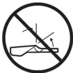
text_image
Prohibition sign showing a hand holding a tool with motion arrows, enclosed in a circleFig. 53
text_image
Prohibition sign with crossed-out car and downward arrows, indicating no change or restrictionFORMA INCORRECTA
Fig. 54
natural_image
Simple line drawing of a car head with two eyes and a curved handle (no text or symbols)
0,6 mm (0,025 pulg.)
This product, its exhaust, and other substances that may become airborne from its use may contain chemicals, including lead, known to the State of California to cause cancer, birth defects, or other reproductive harm. Wash hands after handling.
PROPOSITION 65 DE LA CALIFORNIE

VERTISSEMENT :
For parts or service, contact your nearest Homelite authorized service dealer. Be sure to provide all relevant information when you call or visit. For the location of the authorized service dealer nearest you, please call 1-800-242-4672 or visit us online at www.homelite.com.
REPAIR PARTS
The model number of this product is found on a plate or label attached to the housing. Please record the serial number in the space provided below.
MODEL NO.
SERIAL NO.

DÉPANNAGE
1428 Pearman Dairy Road, Anderson, SC 29625
1-800-242-4672 • www.homelite.com
A subsidiary of Techtronic Industries Co., Ltd. • OTC: TTNDY