
Paint Crew - Paint gun WAGNER - Free user manual and instructions
Find the device manual for free Paint Crew WAGNER in PDF.

| Product Type | High Pressure Airless Paint Sprayer |
| Brand | WAGNER |
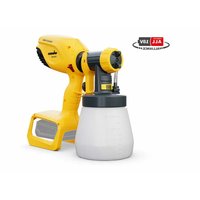
| Model | Paint Crew |
| Power Supply | 230 V - 240 V, 50 Hz |
| Maximum Pressure | 19.3 MPa (193 bar) |
| Flow Rate at 140 bar | 0.9 L/min |
| Container Capacity | 7.5 L |
| Weight Ready to Spray | 10.5 kg |
| High Pressure Hose Length | 7.5 m |
| Nozzles Supplied | 409 (angle 40°, ø 0.23 mm) and 515 (angle 50°, ø 0.38 mm) |
| Filters Supplied | Red filter (fluid materials) and white filter (thick materials) |
| Pump Type | Piston Pump |
| Maximum Noise Level | 81 dBA |
| Maximum Material Temperature | 43 °C |
| Usable Materials | Water-based paints, interior emulsions, acrylics, glazes, wood protection products, strippers, primers, disinfectants, oils (non-solvent) |
| Safety | Safety lock on trigger, mandatory grounding, injection protection |
| Maintenance | Clean after each use, regular cleaning of filters and nozzle |
| Wear Parts | Nozzles, filters, seals (available as spare parts) |
| Warranty | 2 years (excluding wear parts and commercial use) |
| Standards | CE, EN 60335-1, EN 1953 |
Frequently Asked Questions - Paint Crew WAGNER
User questions about Paint Crew WAGNER
0 question about this device. Answer the ones you know or ask your own.
Ask a new question about this device
Download the instructions for your Paint gun in PDF format for free! Find your manual Paint Crew - WAGNER and take your electronic device back in hand. On this page are published all the documents necessary for the use of your device. Paint Crew by WAGNER.
USER MANUAL Paint Crew WAGNER
natural_image
Line drawing of a steam purifier with hoses and control panel (no text or symbols)
natural_image
Warning symbol: black exclamation mark inside a triangle (no text or numbers)natural_image
Mechanical diagram showing a pipe connection with arrows indicating motion (no text or symbols)natural_image
Technical illustration of a mechanical assembly with hands and a tool (no text or symbols)natural_image
Technical illustration of a mechanical assembly with a magnified inset showing internal components (no text or symbols)PISTOLE ENTSICHERN
natural_image
Technical line drawing of a spray gun and its internal structure (no text or symbols)natural_image
Hand holding a spray gun applying paint to a surface (no text or symbols visible)natural_image
Technical illustration of a spray gun and a mechanical component, showing internal structure with no visible text or symbols.natural_image
Line drawing of a hand inserting a spring into a coiled spring (no text or symbols)
natural_image
Technical line drawing of a mechanical device with internal components and a separate view (no text or symbols)natural_image
Hand holding a spray gun with spray nozzle, spraying water onto a surface (no text or symbols visible)natural_image
Solid black rectangle with horizontal white stripes (no text or symbols)natural_image
Technical illustration of a spray gun and a mechanical component, showing internal structure with no visible text or symbols.natural_image
Hand holding a spray gun applying paint to a surface (no text or symbols visible)natural_image
Technical line drawing of a mechanical assembly with hands and a tool (no text or symbols)natural_image
Technical illustration of a mechanical clamp or clamp tool with a hanger and directional arrow (no text or symbols)

natural_image
Technical diagram of a mechanical assembly with no visible text or symbolsnatural_image
Technical line drawing of a mechanical assembly with springs and housing (no text or symbols)natural_image
Mechanical diagram showing a pipe connection with arrows indicating motion (no text or symbols)WARTUNG
TÄGLICHE WARTUNG
natural_image
Illustration of a coiled cable or hose with a connector (no text or symbols visible)Deutsch
SPRITZGERÄT

OWNER'S MANUAL • READ THIS MANUAL FOR COMPLETE INSTRUCTIONS

natural_image
Line drawing of a steam purifier with hoses and control panel (no text or symbols)
natural_image
Warning symbol: white exclamation mark inside a triangle on black background (no text or numbers)! NOT FOR COMMERCIAL USE !
USABEL MATERIALS
Only for water based materials.
- Internal emulsions
- Paints
- Acrylic paints
- Glazes
- wood preservatives
- Mordants
- Primers
- Wash primer
- Plant protective agents
- Under sealants
- Hollow-space sealants
- Disinfection agents
- Oils
UNSUITABLE MATERIALS
- Solvent based paints and lacuers
- Paints and lacquers containing heavily abrasive components like outdoor emulsion / dispersion wall paints
- Silicate paints
WARNING!
Airless-equipment creates an extreme high spray pressure.
- Never bring fingers, hands or other body parts in contact with the spray jet!
Never point the spray gun at oneself, other persons or animals.
Never operate the spray gun without protection.
Attention!
Injury hazard through injection underneath the skin!
With skin injuries caused by coating material or solvents immediately consult a physician. Inform the physician regarding the used coating material or the solvent that caused the injury.
-
In accordance with the manual, following rules should be observed prior to each start-up:
-
Faulty equipment is not to be operated.
-
Secure Wagner-spray gun with safety catch at trigger handle.
-
Verify earth.
-
check all connections for tightness.
Instructions for regular cleaning and maintenance of the equipment should be followed strictly.
-
Prior to all maintenance on the equipment and after every interruption following guidelines should be observed:
-
Relieve pressure in spray gun and hose.
- Secure Wagner-spray gun with safety catch at trigger handle.
- Switch off motor.
Pay attention to safety! SAFETY INSTRUCTIONS FOR
AIRLESS SPRAYING
- Read the manual carefully and follow the given instructions to avoid danger.
- Only use spray materials with a flash point of 21^ C ( 32^ C in UK) or higher, without additional heating.
- In workplaces falling under the explosion protection regulations, the equipment is not to be used.
- When spraying, there should not be any ignition sources in the area; e.g. open fire, smoking of cigarettes, cigars or tobacco-pipes, sparks, incandescent wire, hot surfaces etc.
- Attention! Hazard of injury through injection. Never point the spray gun at oneself, other persons and animals. Never touch the spray jet with the fingers or the hand. Due to the extreme high spray pressure, it causes very serious injuries. Never use the spray gun without contact protection. Always secure the spray gun when assembling or dismantling the nozzle and during an intermission, in order to avoid accidental operation.
- When spraying, wear respiratory equipment and safety glasses. To avoid illnesses follow manufacturer's handling instructions of the used materials, solvents and cleansing agents when preparing, processing and cleaning the equipment. To protect the skin, protective clothing, gloves and possibly skin lotion are required.
- The spray gun and the high pressure hose between machine and spray gun should comply with the rated pressure of the machine. Exclusively use WAGNER-original high-pressure hoses.
- As a result of flowspeed, electrostatic charging is possible. Upon discharge, this can lead to the formation of sparks or flames. Therefore, it is essential that the equipment is always earthed through the electrical installation. The electrical connection should always be made through socket outlets with earthing contact in accordance with regulations.
- When working indoors, an adequate ventilation should be guaranteed to exhaust solvent fumes.
- Extraction systems should be installed on site in accordance with local regulations.

SAFETY INFORMATION • READ ALL SAFETY
INFORMATION BEFORE OPERATING THE EQUIPMENT

- The objects to be coated have to be earthed.
- Cleaning of equipment. Never spray off equipment with a sharp jet, especially not with a high-pressure or steam-pressure cleaner. Short circuit hazard through penetrating water.
- Do not spray any liquid of unknown hazard potential.
- Cover areas that are not to be sprayed. Keep in mind when working that wind, for example, can transport paint mist over great distances and cause damage.
Manual
Congratulations for the purchase of your WAGNER Airless high pressure spray gun.
Read this manual carefully before the initial use of this equipment and observe the safety instructions. Keep manual and safety instructions carefully stored.
You have purchased a quality product which requires careful maintenance and care in order to function perfectly.
Important! After each use, the equipment should be cleaned.
Not cleaning the equipment leads to malfunctioning! For faults caused by crud, no guarantee claim will be granted. In case of malfunctioning, check the cleaned equipment once again prior to sending it in to the service department.
Technical data Paint Crew
Voltage 230V-240V, 50 Hz
Power consumption 625 W
Maximum pressure 19,3 MPa
(193 bar)
Flow rate at 140 bar (0 bar) 0,9 l/min
(1,6 l/min)
Maximum temperature of coating material 43°C
Maximum sound level 81 dBA)*
Maximum ambient temperature 40°C
Pump system piston pump
volume upper container, max. 7,5 l
Turning nozzle, with fast cleaning ability 409 + 515
Weight, ready to spray 10,5 kg

WARNING!
If the supply cord of this appliance is damaged, it must only be replaced by a repair shop appointed by the manufacturer, because special purpose tools are required.
Warning: Do not connect the blue or brown wire to the earth terminal of the plug! The wires in this mains lead are coloured in accordance with the following code:
green/yellow = earth blue = neutral brown = live
As the colours of the wires in the mains lead of this appliance may not correspond with the coloured markings identifying the terminals in your plug, proceed as follows:
The wire which is coloured green and yellow must be connected to the terminal in the plug which is marked with the letter E or by the earth symbol or coloured green or green and yellow.
◆ The wire which is coloured blue must be connected to the terminal which is marked with the letter N or coloured black.
◆ The wire which is coloured brown must be connected to the terminal which is marked with the letter L or coloured brown.
◆ Should the moulded plug have to be replaced, never re-use the defective plug or attempt to plug it into a different 13 A socket. This could result in an electric shock.
◆ Should it be necessary to exchange the fuse in the plug only use fuses approved by ASTA in accordance with BS 1362. 13 Amp fuses may be used.
◆ To ensure that the fuse and fuse carrier are correctly mounted please observe the provided markings or colour coding in the plug.
◆ After changing the fuse, always make sure that the fuse carrier is correctly inserted. With out the fuse carrier, it is not permissible to use the plug.
◆ The correct fuses and fuse carriers are available from your local electrical supplies stockist.
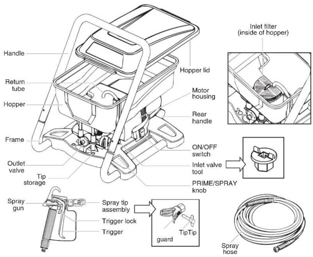
COMPONENTS AND ASSEMBLY
COMPONENTS
- Spray gun with filter
- Spray tip assembly
- 7,5 mtr. long, 1/4 Zoll diameter high pressure hose.
TOOLS NEEDED FOR ASSEMBLY
- Two adjustable wrenches.
WARNING
Do not plug in the unit until setup is complete.
CONTROLS AND FUNCTIONS
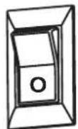
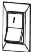
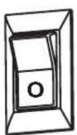
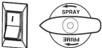
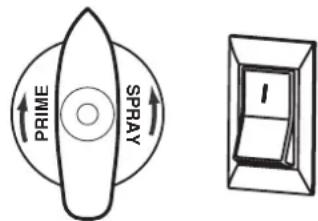
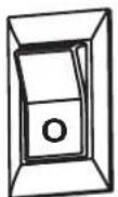
ON/OFF switch.....The ON/OFF switch turns the unit on and off (O = OFF, I = ON)
Spray Gun ....The spray gun controls the delivery of the fluid being pumped.
Spray Hose....The spray hose connects the gun to the pump.
Return Tube......Fluid is sent back out through the return tube to the hopper when priming.
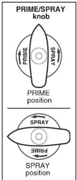
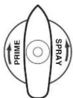
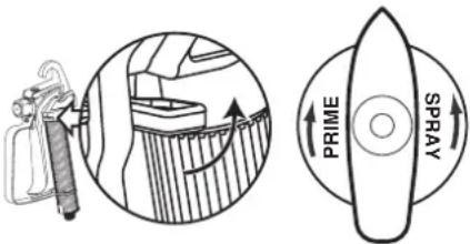
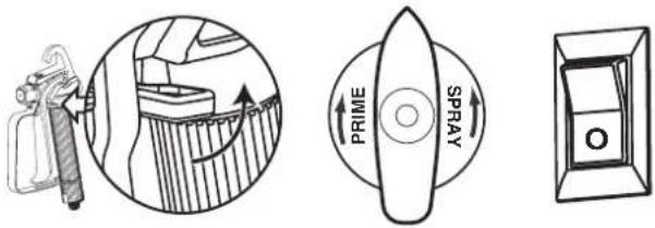
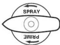
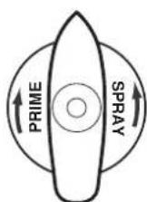
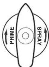
PRIME/SPRAY knob .....The PRIME/SPRAY knob directs fluid to the spray hose when set to SPRAY, or the return tube when set to PRIME.

ASSEMBLY

Place the handle over the unit frame. Insert the bolts and tighten the wing nuts over the lock washers.
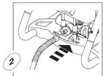
natural_image
Mechanical diagram showing a pipe connection with arrows indicating motion (no text or symbols)Thread one end of the high pressure spray hose to the outlet valve. Tighten with an adjustable wrench. Attach return tube to hopper.
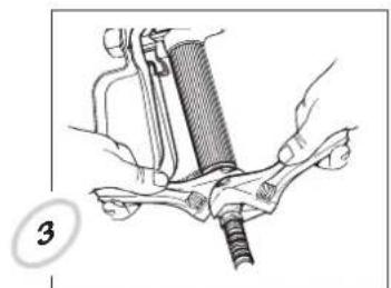
natural_image
Illustration of hands using a mechanical tool to adjust or install a component (no text or symbols visible)Thread the other end of the hose to the spray gun. Hold the gun with one adjustable wrench, and tighten the hose nut with the other.
LOCKING AND UNLOCKING THE GUN

WARNING

Always lock the trigger off when attaching the spray tip or when the spray gun is not in use.
LOCKING THE GUN
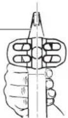
The gun is secured when the trigger lock is at a 90° angle (perpendicular) to the trigger in either direction.

natural_image
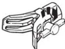
Technical illustration of a mechanical device with an inset showing a magnified view of internal components (no text or symbols)UNLOCKING THE GUN
To unlock the gun, turn the trigger lock to be in line with the trigger.

natural_image
Technical line drawing of a spray gun and its internal structure (no text or symbols)The spray tip SHOULD NOT be attached until after the sprayer and spray hose has been purged and primed.
PLUGGING IN THE SPRAYER
-
Check that the ON/OFF switch is in the OFF position.
-
The connection must be made by correctly grounded plug socket.

PRESSURE RELIEF PROCEDURE
WARNING
Be sure to follow the pressure relief procedure when shutting the unit off FOR ANY PURPOSE. This procedure is used to relieve pressure from the spray hose.
-
Lock the spray gun off and flip the ON/OFF switch to the OFF position.
-
Turn the PRIME/SPRAY knob to PRIME.

natural_image
Illustration of a hand using a spray gun to apply material onto a surface (no text or symbols visible)-
Unlock the spray gun and then trigger it onto a scrap piece of wood or cardboard.
-
Lock the spray gun.
EMPTYING THE HOPPER
Follow these instructions if the hopper is filled with material and 1) your sprayer malfunctions or 2) you finish your spraying project without using all the material in the hopper.
- Perform all the steps of the Pressure Relief Procedure (page 5).


natural_image
Technical illustration of a spray gun and its internal structure, showing no text or symbols-
Remove the lid from the hopper.
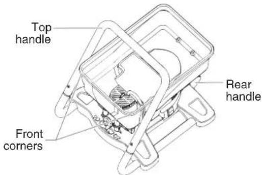
-
Grab top handle of the sprayer with one hand, grab rear handle with the other.
-
Lift and tilt the sprayer so that material will pour from one of the front corners of the hopper and into its original container.
WARNING
CAUTION
The unit, when filled with spraying material, can be heavy. Make sure to lift with your legs and not your back in order to reduce the risk of injury.
Make sure your floors and furnishings are protected with drop cloths to avoid property damage.
PAINT STRAINING
It is recommended that in order to avoid premature tip and filter clogging you should strain your paint before spraying. Follow manufacturer's recommendations.
CHOOSING THE CORRECT SPRAY GUN FILTER
Use the proper gun filter based on the tip size being used.
Tip Size Paint Filter
409 For thin materials like Red filter
40° spray angle/ - Acrylic paints
0,23 mm hole - Primers
- Stains...
515 For thick materials like White filter
50° spray angle/ - Internal emulsions
0,38 mm hole - Latex paints
- Hollow-space sealants...
PURGING AND PRIMING
PURGING AND PRIMING THE PUMP
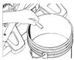
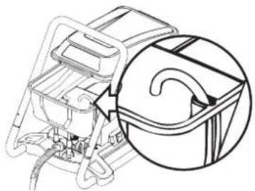
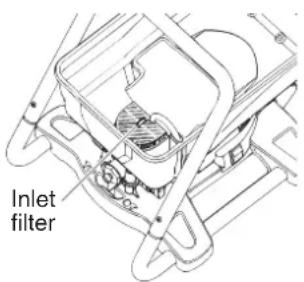
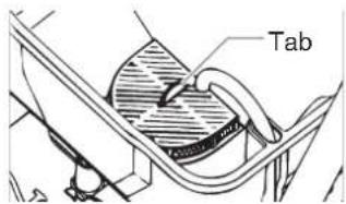
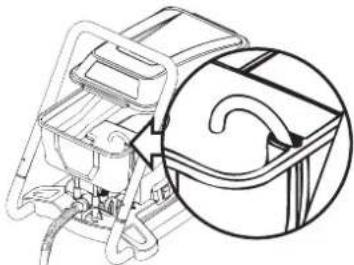
- Make sure the inlet filter is in place inside the hopper. If it is not, snap in place as shown.
- Push the tab on top of the filter down once. This will ensure proper operation of the inlet valve.
- Pull the return tube from the hopper and hold it over a waste container.
- Turn the PRIME/SPRAY knob to PRIME.
- Plug in the sprayer, and move the ON/OFF switch to the ON position.
Any fluids remaining in the pump and the return tube will flow out of the return tube. Let the pump run until no fluid is coming from the return tube.
- Switch the pump to OFF. Remove the return tube from the waste container and secure it to the hopper.

natural_image
Line drawing of a hand inserting a spring into a container (no text or symbols)
natural_image
Technical line drawing of a mechanical device with internal components and a circular inset showing airflow or flow direction (no text or symbols)- Fill your hopper with the material you plan to spray. Do not exceed the fill line as shown. Replace the hopper lid.
- Leave the PRIME/SPRAY knob on PRIME and switch your unit ON once more and make sure that material is flowing from the return tube.
PURGING AND


Your sprayer is now purged. Move to Purging and Priming the Spray Hose.
PRIMING THE SPRAY HOSE
- Unlock the spray gun and turn the PRIME/SPRAY knob to PRIME.
Your spray tip SHOULD NOT be attached to your spray gun when purging your spray hose.

- Trigger and HOLD the spray gun into a waste container


If the PRIME/SPRAY knob is still on SPRAY, there will be high pressure in the hose and spray gun until the PRIME/SPRAY knob is turned to PRIME.
- While holding the trigger, switch the pump ON.
- While holding the trigger, turn the PRIME/SPRAY knob to SPRAY. Hold the trigger until all air, water, or solvent is purged from the spray hose and paint is flowing freely (read warnings below).


Keep hands clear from fluid stream.
- Release trigger, turn the PRIME/SPRAY knob to PRIME and turn pump OFF.
- Trigger the gun into the waste container once more to be sure that no pressure is left in the hose.
- Lock the spray gun off.
- Thread the spray tip assembly onto the gun. Tighten by hand.
Begin tightening the tip at this angle

to achieve the desired spray angle when tight.
Your hose is now purged and primed.
SPRAYING
PRACTICE
CAUTION
Be sure that the paint hose is free of kinks and clear of objects with sharp cutting edges.
- Switch the pump ON and turn the PRIME/SPRAY knob to SPRAY.

- When the motor shuts off, unlock the spray gun and spray a test area to check the spray pattern.

When enough pressure has built up in the hose, the motor will shut off automatically. The motor will cycle on and off automatically as it needs pressure.

Good spray pattern

natural_image
Solid black rectangle with horizontal white stripes (no text or symbols)Bad spray pattern (tailing)
If your pattern is tailing, your spray tip might have an obstruction, your spray gun filter might be clogged or your spray tip might be worn or color is diluted too few. Refer to Spraying Troubleshooting on the next page.
SPRAYING TECHNIQUE
The key to a good paint job is an even coating over the entire surface. This is done by using even strokes. Follow the TIPS, below.
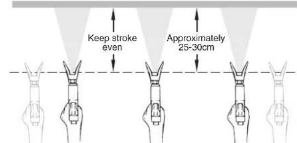
TIP: Keep your arm moving at a constant speed and keep the spray gun at a constant distance from the surface. The best spraying distance is 25 to 30 cm between the spray tip and the surface.
Even coat throughout
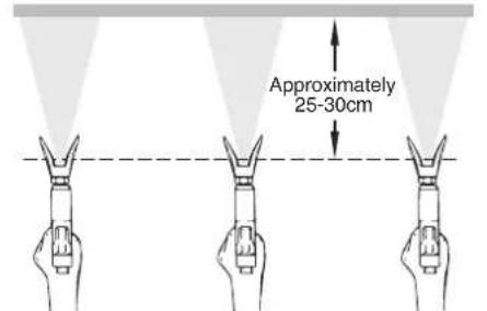
Keep stroke smooth and at an even speed.
TIP: Keep the spray gun perpendicular to the surface, otherwise one end of the pattern will be thicker than the other.
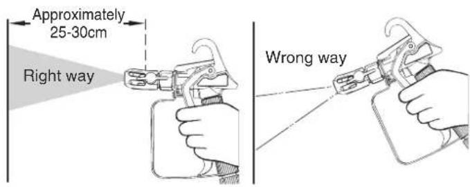
TIP: Keep the spray gun at right angles to the surface. This means moving your entire arm back and forth rather than just flexing your wrist.
Light Coat Ligh Heavy Coat

natural_image
Three hand gestures with pointed tips under a spotlight, no text or symbols presentDo not flex wrist while spraying.
TIP: The spray gun should be triggered by turning it on and off with each stroke. Do not trigger the gun during the middle of a stroke. This will result in an uneven spray and splotchy coverage.
Proper way to trigger the spray gun
Start stroke End stroPull trigger Release triggerKeep steady
ADDITIONAL TIPS
Overlap each stroke by about 30%. This will ensure an even coating.
When you stop painting, follow PRESSURE RELIEF PROCEDURE and unplug electrical cord.
Keep the hopper lid placed on the hopper during spraying. This will prevent debris from falling into your spray material. IF YOU EXPECT TO BE AWAY FROM YOUR SPRAYER FOR MORE THAN ONE HOUR, FOLLOW THE SHORT-TERM STORAGE PROCEDURE DESCRIBED IN THE STORAGE SECTION OF THIS MANUAL (page 11).
SPRAYING TROUBLESHOOTING
The following is a short list of minor difficulties you might encounter while spraying. If any of these occur, it will reduce the flow of material, making your spray pattern poor, or material will fail to spray from the gun.
• Clogged spray tip
• Clogged gun filter
• Clogged inlet filter
Follow the guidelines on this page to correct any one of these problems.
UNCLOGGING THE SPRAY TIP


Do not attempt to unclog or clean the tip with your finger.

Do not use a needle or other sharp pointed instrument to clean the tip. The hard tungsten carbide can chip.
If the spray pattern becomes distorted or stops completely while the gun is triggered, follow these steps:
- Turn the pump off, and release the trigger and lock the gun off.

natural_image
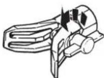
Technical illustration showing a device with a magnified inset of its internal structure (no text or symbols)- Rotate the reversible tip arrow 180^ so that the point of the arrow is toward the rear of the gun (CLEAN position).
Under pressure, the spray tip may be very difficult to turn. Turn the PRIME/SPRAY knob to PRIME and trigger the gun. This will relieve pressure and the tip will turn more easily.
- Turn the PRIME/SPRAY knob to SPRAY.
natural_image
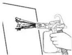
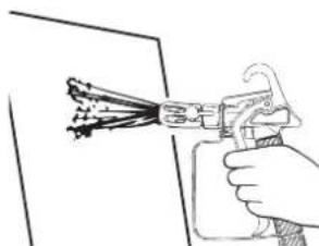
Hand holding a spray gun applying paint to a surface (no text or symbols visible)- Unlock the gun and squeeze the trigger, pointing the gun at a scrap piece of wood or cardboard. This allows pressure in the spray hose to blow out the obstruction. When the nozzle is clean, paint will come out in a high
If paint still will not spray from the spray tip, follow the steps on the next column.
- Release the trigger and lock the gun off.
- Reverse the tip so the arrow points forward again (SPRAY position).
- Unlock the gun and resume spraying.
UNCLOGGING THE SPRAY GUN FILTER
This filter must be cleaned every time you use your sprayer. When using thicker paints, the filter might need to be cleaned more often.
- Perform Pressure Relief Procedure (page 5).
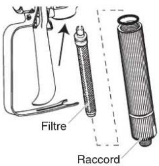
- Unclip the trigger guard from the filter housing by pulling outward from the filter housing. Unscrew the housing.
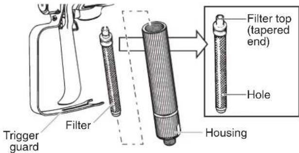
- Remove the filter from the spray gun housing and clean with the appropriate cleaning solution (warm, soapy water)
When cleaning filter, look for sediments in the spraying material you are using. Refer to Paint Straining, (page 5).
- Inspect the filter for holes (see Hole picture, above). Replace if holes are found.

NEVER POKE THE FILTER WITH A SHARP INSTRUMENT!
- Replace the cleaned filter, tapered end first, into the gun housing.
The tapered end of the filter must be loaded properly into the gun. Improper assembly will result in a plugged tip or no flow from the gun. - Replace the housing and spring and snap the trigger guard back into the housing.
UNCLOGGING THE INLET FILTER
- Perform Pressure Relief Procedure, (page 5).
- Empty the hopper of all spraying material (see Emptying the Hopper, page 5).
- Remove the inlet filter from the hopper. You may need to use a screwdriver to pry the filter loose.
- Clean the inlet filter using the appropriate cleaning solution (warm, soapy water).
- Replace filter.

If after having completed all of the steps on this page you are still experiencing problems spraying, refer to the TROUBLESHOOTING page (page 12)
IMPORTANT CLEANING NOTES!
READ THESE NOTES AND WARNINGS BEFORE YOU START TO CLEAN YOUR SPRAYER!
- Clean your sprayer and components using warm, soapy water.
• Make sure to dispose cleaning solution properly when finished cleaning your sprayer. - Thorough cleaning and lubrication of the sprayer is the most important step you can take to ensure proper operation after storage.
PURGING THE PAINT HOSE
These steps will allow you to recover excess paint left over in the paint hose.
- Lock the gun, remove spray tip assembly, and turn the PRIME/SPRAY knob to PRIME.
- Dump out any remaining spray material from the hopper back into its container (see Emptying the Hopper, page 5).
- Fill the hopper with the appropriate cleaning solution.
- Hold the spray gun against the side of the paint can and hold the trigger.

- While holding the trigger, turn the pump ON, and turn the PRIME/SPRAY knob to SPRAY.
Let the pump run until all paint is purged from the hose and cleaning solution is coming out of the gun.
- Release the trigger and turn the PRIME/SPRAY knob to PRIME.
- Hold the spray gun against the side of a separate container and hold the trigger.

- Turn the PRIME/SPRAY knob to SPRAY and trigger the gun until the fluid coming out of the gun is clear.
You might need to add more cleaning solution to the hopper.
- Turn the PRIME/SPRAY knob to PRIME and trigger gun once more to relieve pressure.
- Move on to Rinsing the Hopper.
RINSING THE HOPPER
- Thoroughly rinse out the hopper using the appropriate cleaning solution.
Make sure you do not drip any cleaning solution into the motor housing.
- Remove the inlet filter from the bottom of the hopper and clean. You may need to use a screwdriver to pry the filter loose.
- Replace the filter and properly dispose of the cleaning solution.
FLUSHING THE SPRAYER
- Fill the hopper with NEW cleaning solution.
- Turn the PRIME/SPRAY knob to PRIME, turn the pump to ON.
- Let the pump circulate the cleaning solution out the return tube for 2-3 minutes.
- Turn the pump OFF.

- Properly dispose of cleaning solution and move on to Cleaning the Spray Gun Components, next page.
CLEANUP (CONTINUED)
INLET/OUTLET VALVES
CLEANING THE SPRAY GUN COMPONENTS
- Perform Pressure Relief Procedure, page 5.
- Remove spray gun from the paint hose using adjustable wrenches.

natural_image
Technical line drawing of a mechanical assembly with hands operating a tool (no text or symbols visible)- Remove filter from spray gun (refer to Unclogging the Spray Gun Filter, page 8).
- Remove spray tip from spray guard assembly.
natural_image
Technical illustration of a clamp tool with a hanger and directional arrow (no text or symbols)
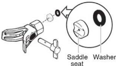
- Clean spray tip and filter with a soft-bristled brush and the appropriate cleaning solution. Be sure to remove and clean the washer and saddle seat located in the rear of the spray tip assembly.

natural_image
Line drawing of two hands holding a string, no text or symbols present- Pour a few drops of household oil inside the gun housing (see area indicated below by arrow).
- Reassemble spray gun:
• install gun filter tapered-end first, and,
• install spray tip, saddle seat and washer, and replace spray guard assembly.


- Thread the paint hose back onto the spray gun. Tighten with a wrench.
IMPORTANT!
If you cleaned your pump, it is recommended that you flush the pump again using warm, soapy water to prepare it for storage. Repeat Flushing the Pump instructions.
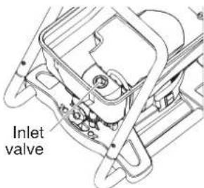
CLEANING THE INLET VALVE
Cleaning or servicing the inlet valve may be required if the unit has priming problems. This may be caused by improper cleaning and/or storage. Replacement kits may be ordered by calling customer service.
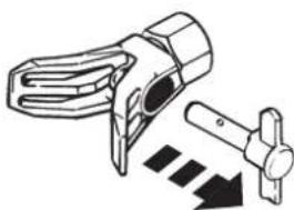
- Remove the inlet filter from the bottom of the hopper. You may need to use a screwdriver to pry the filter loose.
- Insert the inlet valve tool into the inlet fitting. Twist counter-clockwise and remove from its housing.

natural_image
Mechanical component diagram showing a valve and adjustment knob (no text or symbols)You will need to attach the inlet valve tool to a ratchet 3/8 Zoll wrench extension in order to remove it.
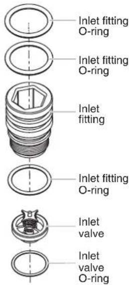
- Inspect the three inlet fitting O-rings on the inlet fitting. Clean or replace, and lubricate with household oil.
DO NOT remove the O-rings on the inlet fitting to clean them. Remove ONLY if you plan to replace them.
- Retrieve the inlet valve and the inlet valve O-ring from the inlet fitting housing. Clean or replace and lubricate the O-ring with a light household oil.
- Set the inlet valve O-ring back into the housing, and set the inlet valve on top of it.
- Replace inlet fitting into the housing. Tighten with the inlet valve tool and ratchet.
REPLACING THE OUTLET VALVE
Replacement of the outlet valve may be necessary if your spray performance remains poor after having performed all the steps contained in the Spraying Troubleshooting section of this manual. Replacement valves are available by calling customer service.
- Unscrew the outlet valve from the outlet valve housing using an adjustable wrench.
- Inspect the inside of the outlet valve housing. Remove any accumulated paint.
- Replace with a new outlet valve. Tighten into outlet valve housing with an adjustable wrench.

natural_image
Technical line drawing of a mechanical assembly with no visible text or symbolsSTORAGE
SHORT-TERM STORAGE (UP TO 8 HOURS)
SHUTDOWN
- Perform all the steps of the PRESSURE RELIEF PROCEDURE (page 5).
-
Pour 1/2 cup water slowly on top of the paint to prevent it from drying. Replace the hopper lid.
-
Wrap the spray gun assembly in a damp cloth and place it in a plastic bag. Seal the bag shut.

-
Unplug the sprayer.
-
Place the sprayer in a safe place out of the sun for short-term storage.
STARTUP
-
Remove the gun from the plastic bag and stir the water into the paint.
-
Check to be sure the PRIME/SPRAY knob is set to PRIME.

-
Plug sprayer in and turn the switch to ON.
-
Turn the PRIME/SPRAY knob to SPRAY.
-
Test the sprayer on a practice piece and begin spraying.
PREPARING THE SPRAYER FOR LONG-
TERM STORAGE
- Make sure you have already completed the Cleanup steps on pages 9-10.
- Remove the inlet filter. You may need to use a screwdriver to pry it loose.

- Pour approximately two ounces of light household oil into the inlet valve.
-
Remove hose from outlet valve, place a rag over the outlet valve, and turn the switch ON. Let the unit run for five seconds.
-
Switch the pump OFF.

- Replace the inlet filter and push the tab on the filter.
-
Wipe the entire unit, hose and gun with a damp cloth to remove accumulated paint.
-
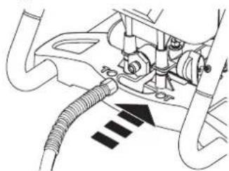
Replace the high pressure hose to the outlet valve and replace the hopper lid.
natural_image
Mechanical assembly diagram showing hoses and tubing with no visible text or symbolsMAINTENANCE
DAILY MAINTENANCE
The only daily maintenance necessary is thorough cleaning. Follow the cleaning procedures in this manual.
EXTENDED MAINTENANCE
Some pump parts eventually wear out from use and must be
replaced. The following is a list of available repair kits. Pump performance is the only reliable indicator of when to replace wear parts. Refer to the Troubleshooting section for more information on when to use these kits.
Kit Part # Description
0418912 Inlet and outlet valve kit Service kits available at WAGNER sales shelf
TROUBLESHOOTING
WARNING
Before servicing, always release system pressure by following PRESSURE RELIEF PROCEDURE (page 5).
PROBLEM
| A. The sprayer does not start. |
| B. The sprayer starts but does not draw in paint when the PRIME/SPRAY knob is set to PRIME. |
| C. The sprayer draws up paint but the pressure drops when the gun is triggered. |
| D. The PRIME/SPRAY valve is on SPRAY and there is flow through the return tube. |
| E. The spray gun leaks. |
| F. The tip assembly leaks. |
| G. The spray gun will not spray. |
| H. The paint pattern is tailing. |
CAUSE
| 1. The sprayer is not plugged in. |
| 2. The ON/OFF switch is set to OFF. |
| 3. The sprayer shuts off while still under pressure. |
| 4. No voltage is coming from the wall plug. |
| 5. The extension cord is damaged or has too low a capacity. |
| 6. There is a problem with the motor. |
| 1. The unit will not prime properly or has lost prime. |
| 2. The hopper is empty. |
| 3. The unit is not on level ground. |
| 4. The inlet filter is clogged. |
| 5. The inlet or outlet valve is stuck. |
| 6. The inlet valve is worn or damaged. |
| 7. The PRIME/SPRAY valve is plugged. |
| 1. The spray tip is worn. |
| 2. The inlet filter is clogged. |
| 3. The gun or spray tip filter is plugged. |
| 4. The paint is too heavy or coarse. |
| 5. The outlet valve assembly is dirty or worn. |
| 6. The inlet valve assembly is damaged or worn. |
| 1. The PRIME/SPRAY valve is dirty or worn. |
| 1. |
| Internal parts of the gun are worn or dirty. |
| 1. The tip was assembled incorrectly. |
| 2. A seal is worn. |
| 1. The spray tip or the gun filter is plugged. |
| 2. The spray tip is in the CLEAN position. |
| 3. PRIME/SPRAY knob not set on SPRAY. |
| 1. The gun, the tip, or the inlet filter is plugged. |
| 2. The tip is worn. |
| 3. The paint is too thick. |
| 4. Pressure loss. |
SOLUTION
| 1. Plug the sprayer in. |
| 2. Turn the ON/OFF switch to ON. |
| 3. Motor will cycle ON and OFF while spraying as it needs pressure. This is normal. Resume painting. |
| 4. Properly test the power supply voltage. |
| 5. Replace the extension cord. |
| 6. Take sprayer to Wagner Authorized Service Center. |
| 1. Try to prime the unit again. |
| 2. Refill the hopper. |
| 3. Relocate unit to level ground. |
| 4. Clean the inlet filter. |
| 5. Clean the inlet and outlet valves and replace any worn parts.* Inlet may be stuck from old paint. Push inlet filter tab to release. |
| 6. Replace the inlet valve.* |
| 7. Take sprayer to Wagner Authorized Service Center. |
| 1. Replace the spray tip with a new tip.** |
| 2. Clean the inlet filter. |
| 3. Clean or replace the proper filter. Always keep extra filters on hand. |
| 4. Thin or strain the paint. |
| 5. Clean or replace the outlet valve assembly.* |
| 6. Replace the inlet valve.* |
| 1. Take sprayer to Wagner Authorized Service Center. |
| 1. Take the sprayer to a Wagner Authorized Service Center. |
| 1. Check the tip assembly and assemble properly. |
| 2. Replace the seal.* |
| 1. Clean the spray tip or gun filter. Review Unclogging the Spray Tip. |
| 2. Put the tip in the SPRAY position. |
| 3. Turn the PRIME/SPRAY knob to SPRAY. |
| 1. Clean the filters and strain the paint. |
| 2. Replace the spray tip. |
| 3. Thin the paint. |
| 4. Refer to Causes and Solutions for problem C. |
SPRAY GUN
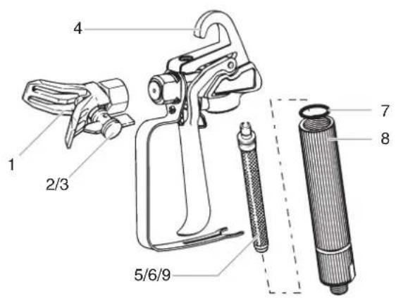
English
Item Part # Description Quantity
1 0501011 Guard Assembly ....1
2◆ 0418910 Tip 409....1
3◆ 0418911 Tip 515....1
4 0515229 Complete gun assembly ....1
5◆ 0418913 Filter red....1
6◆ 0418914 Filter white....1
7◆ 0515228 Seal....1
8 0515227 Filter housing....1
9◆ 0418915 Filter yellow....1
◆ Wear parts: Not covered by guarantee
Wear parts available at WAGNER sales shelf
SPRAY HOSE
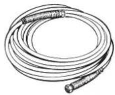
natural_image
Illustration of a coiled cable or hose with a bulbous end cap (no text or symbols)English
Part Number
0270192
Description
1/4" X 7,5 m spray hose
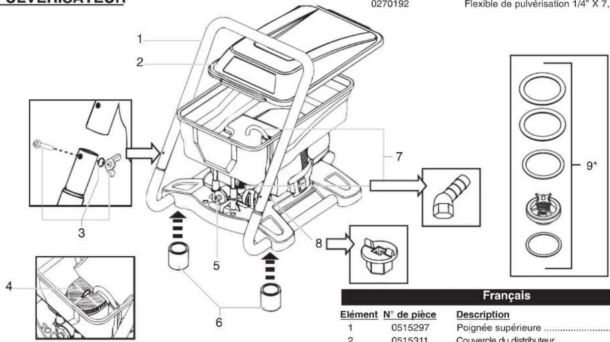
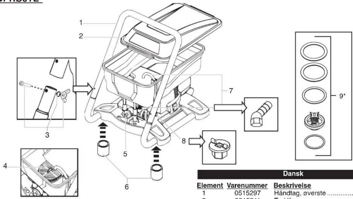
SPRAYER
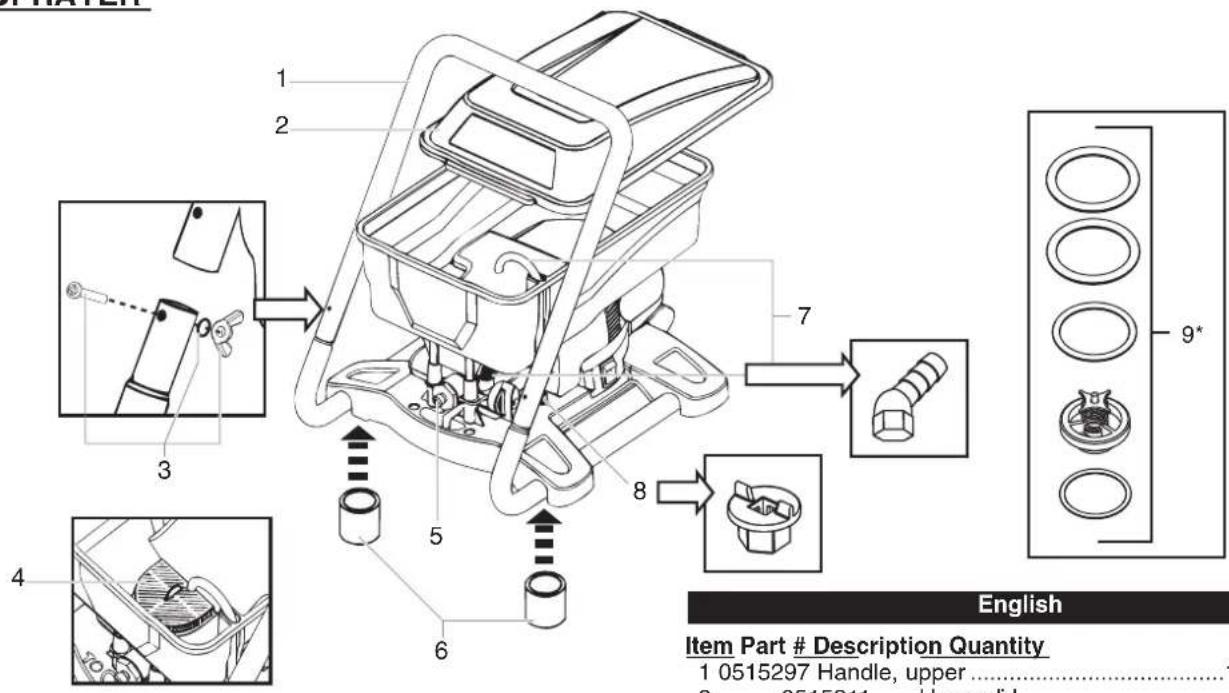
English
Item Part # Description Quantity
1 0515297 Handle, upper ....1
2 0515311 Hopper lid....1
3 0515225 Bolt, washer, and wing nut kit....1
4 0515421 Inlet filter....1
5+9◆ 0418912 Inlet and outlet valve kit....1
6 0515372 Feet....4
7 0515226 Return tube/fitting ....1
8 0515370 Inlet valve tool....1
Replacement parts available by calling customer service.
◆ Wear parts: Not covered by guarantee
Wear parts available at WAGNER sales shelf
2 years guarantee
The guarantee runs for two years, counting from the date of sale (sales slip).
It covers and is restricted to free-of-charge rectification of faults which are demonstrably attributable to the use of faulty materials in manufacture, or assembly errors; or free-of-charge replacement of the defective parts. The guarantee does not cover incorrect use or commissioning or fitting or repair work which is not stated in our operating instructions.
Wearing parts are also excluded from the guarantee. The guarantee excludes commercial use. We expressly reserve the right to fulfil the guarantee.
The guarantee expires if the tool is opened up by persons other than WAGNER service personnel.
Transport damage, maintenance work and loss and damage due to faulty maintenance work are not covered by the guarantee. Under any guarantee claim, there must be proof of purchase of the tool through submission of the original receipt.
Wherever legally possible, we exclude all liability for injury, damage or consequential loss, especially if the tool has been used for a purpose other than that stated in the operating instructions, commissioned or repaired other than in accordance with our operating instructions or if repairs are performed by someone who is unqualified.
We reserve the right to perform any repairs in excess of those stated in our operating instructions.
Wear parts (marked with ◆ in the parts list) are not covered by the WAGNER guarantee.
In case of guarantee or repair, please refer to your point of sale.
Disposal instructions!

The appliance and accessories should be recycled in an environmentally friendly way. Do not dispose of the appliance with household waste. Support environmental protection by taking the appliance to a local collection point or obtain information from a specialist retailer.
WAGNER®
PAINT CREW®
PULVÉRISATEUR AIRLESS À HAUTES PERFORMANCES
MANUEL DE L'UTILISATEUR • LIRE CE MANUEL POUR OBTENIR DES DIRECTIVES COMPLÈTES

natural_image
Line drawing of a mechanical pump assembly with hoses and control panel (no text or symbols)
natural_image
Warning symbol with exclamation mark inside a triangle (no text or numbers)natural_image
Mechanical assembly diagram showing hoses and tubing with directional arrows (no text or labels)natural_image
Illustration of hands using a mechanical tool to adjust or install a component (no text or symbols visible)natural_image
Technical illustration of a spray gun with a magnified inset showing internal components (no text or symbols)DÉVERROUILLER LE PISTOLET
natural_image
Technical line drawing of a spray gun and a mechanical component, shown with an inset circular detail (no text or symbols)natural_image
Hand holding a spray gun with a tool, spraying water onto a surface (no text or symbols visible)
natural_image
Technical illustration of a spray gun and its internal structure, showing no text or symbolsnatural_image
Line drawing of a hand placing a circular object into a cylindrical container (no text or symbols)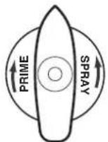


natural_image
Technical line drawing of a mechanical device with internal components and a circular inset view (no text or symbols)natural_image
Hand holding a spray gun with a tool emitting particles from a surface (no text or symbols visible)natural_image
Solid black rectangle with horizontal white stripes (no text or symbols)Formation de filaments
natural_image
Technical illustration of a spray gun and its internal structure, showing no text or symbolsnatural_image
Hand holding a spray gun with multiple wires being sprayed (no text or symbols visible)natural_image
Technical line drawing of a mechanical clamp or bracket assembly (no text or symbols)natural_image
Technical illustration of a clamp tool with a hanger and directional arrow (no text or symbols)
natural_image
Technical diagram of a vehicle's engine compartment showing valve, gear, and directional arrows (no text or labels)natural_image
Technical line drawing of a mechanical assembly with no visible text or symbolsRANGEMENT
RANGEMENT À COURT TERME (JUSQU'À 8 HEURES)
PRÉPARATION POUR LE RANGEMENT
natural_image
Technical diagram of a mechanical assembly with hoses and tubing (no text or symbols)MAINTENANCE
ENTRETIEN QUOTIDIEN
natural_image
Illustration of a coiled cable or hose with two connectors (no text or symbols)Français
PULVÉRISATEUR
natural_image
Technical line drawing of a mechanical device with hoses and control panel (no text or symbols)
natural_image
Warning symbol: white exclamation mark inside a triangle on black background (no text or numbers)! Ikke TIL ERHVERVSMAESSIG BRUG !
BRUGBARE MATERIALER
natural_image
Mechanical diagram showing a vehicle's engine and hoses with directional arrows (no text or labels)natural_image
Illustration of hands using a mechanical tool to adjust or install a component (no text or symbols visible)natural_image
Technical illustration of a mechanical device with a magnified inset showing internal components (no text or symbols)ÄBNING AF PISTOLEN
natural_image
Technical illustration of a spray gun and its internal structure (no text or symbols)natural_image
Hand holding a spray gun applying paint to a surface (no text or symbols visible)
natural_image
Technical illustration of a spray gun and a mechanical component, showing internal structure with no visible text or symbols.natural_image
Line drawing of a hand inserting a circular component into a coiled spring (no text or symbols)


natural_image
Technical line drawing of a mechanical device with internal components and a circular inset view (no text or symbols)natural_image
Solid black rectangle with horizontal white stripes (no text or symbols)natural_image
Three hand gestures with focused lighting, no text or symbols presentnatural_image
Technical illustration showing a door panel and a magnified view of a mechanical component (no text or symbols)natural_image
Hand holding a spray gun applying paint to a surface (no text or symbols visible)natural_image
Illustration of a spray gun and a mechanical component with an arrow indicating motion (no text or symbols)
natural_image
Technical line drawing of a mechanical assembly with hands operating a tool (no text or symbols visible)natural_image
Technical illustration of a mechanical clamp or clamp tool with a hanger and directional arrow (no text or symbols)

natural_image
Technical line drawing of a mechanical component with no visible text or symbolsnatural_image
Technical line drawing of a mechanical assembly with springs and housing (no text or symbols)OPBEVARING
KORTTIDSOPBEVARING (OP TIL 8 TIMER)
NEDLUKNING
- Udfør alle trinene i TRYKUDLIGNINGSPROCEDUREN (side 5).

natural_image
Mechanical assembly diagram showing hoses and tubing with no visible text or symbolsVEDLIGEHOLDELSE
DAGLIG VEDLIGEHOLDELSE
natural_image
Illustration of a coiled cable or hose with a bulbous end cap (no text or symbols)Dansk
Varenummer Beskrivelse
0270192 1/4" X 7,5 m sprøjteslange
SPR∅JTE
CE Declaration of Conformity
We declare under sole responsibility that this product conforms to the following relevant stipulations: 73/23/EWG, 98/37/EWG, 89/336 EWG; 2002/95/EG; 2002/96/EG Applied harmonised norms: EN 60335-1:2002; EN 1953:1998; EN 55014-1:2002; EN 55014-2:2001; EN 61000-3-2:2000; EN 61000-3-3:2001

J. Wagner GmbH
D-88677 Markdorf Managing Director Development Manager

J. Wagner GmbH
Tramway Industrial Estate
Banbury, Oxon OX16 5RN

+44/12 95/26 53 53 +44/12 95/27 54 87


Wagner Spraytech Scandinavia A/S
Kornmarksvej 26
2605 Brøndby

+45/43 27 18 18 +45/43 43 05 28


J. Wagner AG
Industriestraße 22
9450 Altstätten

+41/71/7 57 22 11 +41/71/7 57 23 23


Wagner Sverige AB
Muskötgatan 19
S-254 66 Helsingborg

+46 42 15 00 20 +46 42 15 00 35


Wagner Spraytech Benelux B. V.
Zoonebaan 10
3542 EC-Utrecht

+31/30/2 41 41 55 +31/30/2 41 17 87


Wagner France S.a.r.l.
Copyright by J. Wagner GmbH

Wagner Spol s.r.o.
Nedašovská 345
15500 Praha 5

+420/2/57 95 04 12 +420/2/57 95 10 52


J. Wagner Spraytech Ibérica S.A.
Ctra. N-340, Km 1245,4
08750 Molins de Rei (Barcelona)

+34/93/6 80 00 28 +34/93/6 68 01 56


Adresa servisa:
GMA Elektromehanika d.o.o.
Cesta Andreja Bitenca 115,
41-605 Swietochlowice

+48/32/2 45 06 19 +48/32/2 41 42 51


Adresa servisa:
EL-ME-HO
Horvacanska 25
10000 Zagreb/Kroatien

+385(-1) 3 01 02 68


Wagner Spraytech Australia Pty. Ltd.,
14-16 Kevlar Close,
Braeside, VIC 3195/Australia

+61/3/95 87 20 00 +61/3/95 80 91 20
www.wagner-group.com
Not responsible for errors and changes.


- PISTOLE ENTSICHERN
- WARTUNG
- TÄGLICHE WARTUNG
- USABEL MATERIALS
- UNSUITABLE MATERIALS
- WARNING!
- Airless-equipment creates an extreme high spray pressure.
- Attention!
- Injury hazard through injection underneath the skin!
- Pay attention to safety! SAFETY INSTRUCTIONS FOR
- AIRLESS SPRAYING
- SAFETY INFORMATION • READ ALL SAFETY
- INFORMATION BEFORE OPERATING THE EQUIPMENT
- Manual
- Congratulations for the purchase of your WAGNER Airless high pressure spray gun.
- Important! After each use, the equipment should be cleaned.
- Technical data Paint Crew
- COMPONENTS AND ASSEMBLY
- COMPONENTS
- TOOLS NEEDED FOR ASSEMBLY
- WARNING
- CONTROLS AND FUNCTIONS
- ASSEMBLY
- LOCKING AND UNLOCKING THE GUN
- LOCKING THE GUN
- UNLOCKING THE GUN
- PLUGGING IN THE SPRAYER
- PRESSURE RELIEF PROCEDURE
- EMPTYING THE HOPPER
- CAUTION
- PAINT STRAINING
- CHOOSING THE CORRECT SPRAY GUN FILTER
- Tip Size Paint Filter
- PURGING AND PRIMING
- PURGING AND PRIMING THE PUMP
- PURGING AND
- PRIMING THE SPRAY HOSE
- Keep hands clear from fluid stream.
- SPRAYING
- PRACTICE
- SPRAYING TECHNIQUE
- ADDITIONAL TIPS
- SPRAYING TROUBLESHOOTING
- UNCLOGGING THE SPRAY TIP
- UNCLOGGING THE SPRAY GUN FILTER
- UNCLOGGING THE INLET FILTER
- IMPORTANT CLEANING NOTES!
- READ THESE NOTES AND WARNINGS BEFORE YOU START TO CLEAN YOUR SPRAYER!
- PURGING THE PAINT HOSE
- RINSING THE HOPPER
- FLUSHING THE SPRAYER
- CLEANUP (CONTINUED)
- INLET/OUTLET VALVES
- CLEANING THE SPRAY GUN COMPONENTS
- IMPORTANT!
- CLEANING THE INLET VALVE
- REPLACING THE OUTLET VALVE
- STORAGE
- SHORT-TERM STORAGE (UP TO 8 HOURS)
- SHUTDOWN
- STARTUP
- PREPARING THE SPRAYER FOR LONG-
- TERM STORAGE
- MAINTENANCE
- DAILY MAINTENANCE
- EXTENDED MAINTENANCE
- Kit Part # Description
- TROUBLESHOOTING
- Before servicing, always release system pressure by following PRESSURE RELIEF PROCEDURE (page 5).
- English
- Item Part # Description Quantity
- years guarantee
- Disposal instructions!
- WAGNER®
- DÉVERROUILLER LE PISTOLET
- RANGEMENT
- RANGEMENT À COURT TERME (JUSQU'À 8 HEURES)
- PRÉPARATION POUR LE RANGEMENT
- ENTRETIEN QUOTIDIEN
- BRUGBARE MATERIALER
- ÄBNING AF PISTOLEN
- OPBEVARING
- KORTTIDSOPBEVARING (OP TIL 8 TIMER)
- NEDLUKNING
- VEDLIGEHOLDELSE
- DAGLIG VEDLIGEHOLDELSE
- Dansk
- Varenummer Beskrivelse
- CE Declaration of Conformity
- www.wagner-group.com
Brand : WAGNER
Model : Paint Crew
Category : Paint gun