DW383 - Saw DEWALT - Free user manual and instructions
Find the device manual for free DW383 DEWALT in PDF.

User questions about DW383 DEWALT
0 question about this device. Answer the ones you know or ask your own.
Ask a new question about this device
Download the instructions for your Saw in PDF format for free! Find your manual DW383 - DEWALT and take your electronic device back in hand. On this page are published all the documents necessary for the use of your device. DW383 by DEWALT.
USER MANUAL DW383 DEWALT
text_image
Technical diagram of a mechanical device with numbered parts labeled 1 to 5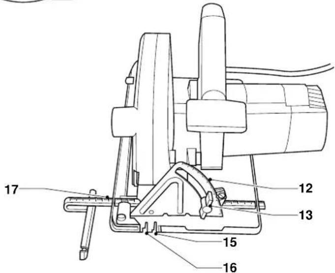
text_image
Technical diagram of a mechanical device with numbered parts labeled 12 through 17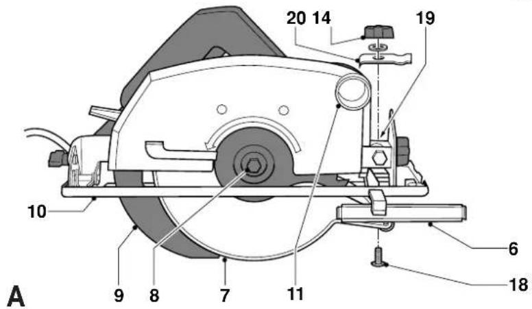
text_image
20 14 19 10 6 A 9 8 7 11 18


text_image
Technical diagram of a mechanical device with numbered parts labeled 10, 13, and 12B
text_image
Technical diagram of a mechanical device with numbered components labeled 7, 8, and 23C


text_image
2 mm MAX 2 mm 24 9D
text_image
Technical diagram of a sewing machine with labeled parts 25 and 26, showing mechanical components and measurement lines.E
271315162822 21


Dansk 1
Deutsch 7
English 14
Español 21
Français 28
Italiano 35
Nederlands 42
Norsk 49
Português 55
Suomi 62
Svenska 68
Türkçe 74
Ελληνικα 81
RUNDSAV DW383
Tillykke!
You have chosen a DeWALT Power Tool. Years of experience, thorough product development and innovation make DeWALT one of the most reliable partners for professional Power Tool users.
Table of contents
| Technical data en - 1 |
| EC-Declaration of conformity en - 1 |
| Safety instructions en - 2 |
| Package contents en - 3 |
| Description en - 4 |
| Electrical safety en - 4 |
| Mains plug replacement (U.K. & Ireland only) en - 4 |
| Using an extension cable en - 4 |
| Assembly and adjustment en - 5 |
| Instructions for use en - 6 |
| Maintenance en - 7 |
| Guarantee en - 7 |
Technical data
| DW383 | ||
| Voltage V 230 | ||
| (U.K. & Ireland only) V 230/115 | ||
| Power input | W 1,700 | |
| No load speed | min ^-1 | 4,900 |
| Maximum cutting depth at 90° | mm 86 | |
| Blade diameter mm max/min | mm 210-235 | |
| Blade body thickness max/min | mm 3 | |
| Blade bore | mm 30 | |
| Weight | kg 8.4 | |
| Fuses: | ||
| Europe | 230 V tools | 10 Amperes, mains |
| U.K. & Ireland | 230 V tools | 13 Amperes, in plugs |
The following symbols are used throughout this manual:

Denotes risk of personal injury, loss of life or damage to the tool in case of non-observance of the instructions in this manual.

Denotes risk of electric shock.
EC-Declaration of conformity

DW383
DEWALT declares that these power tools have been designed in compliance with: 89/392/EEC, 89/336/EEC, 73/23/EEC, EN 50144, EN 55104, EN 55014, EN 61000-3-2 & EN 61000-3-11.
For more information, please contact D≡WALT at the address below, or refer to the back of the manual.
Level of sound pressure according to 86/188/EEC & 89/392/EEC, measured according to EN 50144:
| DW383 | |||
| L_UA | (sound pressure) | dB(A)* | 90.0 |
| L_UAA | (acoustic power) | dB(A) | 102.0 |
* at the operator's ear

Take appropriate measures for the protection of hearing if the sound pressure of 85 dB(A) is exceeded.
Weighted root mean square acceleration value according to EN 50144:
| DW383 | |
| < 2.5 m/s ^2 |
Director Engineering and Product Development Horst Großmann
X. fopsmann
When using Power Tools, always observe the safety regulations applicable in your country to reduce the risk of fire, electric shock and personal injury. Read the following safety instructions before attempting to operate this product. Keep these instructions in a safe place!
General
1 Keep work area clean Cluttered areas and benches can cause accidents.
2 Consider work area environment Do not expose Power Tools to humidity. Keep work area well lit. Do not use Power Tools in the presence of inflammable liquids or gases.
3 Guard against electric shock Prevent body contact with earthed surfaces (e.g. pipes, radiators, cookers and refrigerators). For use under extreme conditions (e.g. high humidity, when metal swarf is being produced, etc.) electric safety can be improved by inserting an isolating transformer or a (FI) earth-leakage circuit-breaker.
4 Keep children away Do not let children come into contact with the tool or extension cord. Supervision is required for those under 16 years of age.
5 Extension cords for outdoor use When the tool is used outdoors, always use extension cords intended for outdoor use and marked accordingly.
6 Store idle tools When not in use, Power Tools must be stored in a dry place and locked up securely, out of reach of children.
7 Dress properly Do not wear loose clothing or jewellery. They can be caught in moving parts. Preferably wear rubber gloves and non-slip footwear when working outdoors. Wear protective hair covering to keep long hair out of the way.
8 Wear safety goggles Also use a face or dust mask in case the operations produce dust or flying particles.
9 Beware of maximum sound pressure Take appropriate measures for the protection of hearing if the sound pressure of 85 dB(A) is exceeded.
10 Secure workpiece Use clamps or a vice to hold the workpiece. It is safer and it frees both hands to operate the tool.
11 Do not overreach Keep proper footing and balance at all times.
12 Avoid unintentional starting Do not carry the plugged-in tool with a finger on the switch. Be sure that the switch is released when plugging in.
13 Stay alert Watch what you are doing. Use common sense. Do not operate the tool when you are tired.
14 Disconnect tool Shut off power and wait for the tool to come to a complete standstill before leaving it unattended. Unplug the tool when not in use, before servicing or changing accessories.
15 Remove adjusting keys and wrenches Always check that adjusting keys and wrenches are removed from the tool before operating the tool.
16 Use appropriate tool The intended use is laid down in this instruction manual. Do not force small tools or attachments to do the job of a heavy-duty tool. The tool will do the job better and safer at the rate for which it was intended.
Warning! The use of any accessory or attachment or performance of any operation with this tool, other than those recommended in this instruction manual may present a risk of personal injury.
17 Do not abuse cord Never carry the tool by its cord or pull it to disconnect from the socket. Keep the cord away from heat, oil and sharp edges.
18 Maintain tools with care Keep the tools in good condition and clean for better and safer performance. Follow the instructions for maintenance and changing accessories. Inspect the tool cords at regular intervals and, if damaged, have them repaired by an authorized DeWALT repair agent. Inspect the extension cords periodically and replace them if damaged. Keep all controls dry, clean and free from oil and grease.
19 Check for damaged parts Before using the tool, carefully check it for damage to ensure that it will operate properly and perform its intended function.
ENGLISH
Check for misalignment and seizure of moving parts, breakage of parts and any other conditions that may affect its operation. Have damaged guards or other defective parts repaired or replaced as instructed.
Do not use the tool if the switch is defective. Have the switch replaced by an authorized DeWALT repair agent.
20 Have your tool repaired by an authorized DEWALT repair agent
This Power Tool is in accordance with the relevant safety regulations. To avoid danger, electric appliances must only be repaired by qualified technicians.
Additional safety rules for circular saws
Plugging into the mains, switching ON and OFF
- Always ensure that the Power Tool is switched OFF before plugging into the mains.
- Remove the blade changing spanner from the saw blade locking screw before switching ON.
- Do not switch OFF before the saw blade is running freely.
When sawing
- Remove all nails and metal objects from the workpiece before starting work.
- Do not attempt to saw extremely small workpieces.
- After switching OFF, never attempt to stop the saw blade by pressing against the side of the blade.
- Never put the saw down on a table or work bench unless switched OFF.
• Always use the riving knife, except for inserted cuts.
Operational protection devices
- Ensure that all devices screening the saw blade are in perfect working order.
- Never jam the saw blade guards.
- Free a jammed saw blade guard immediately and do not use the saw if the guard is jammed.
- Do not remove the riving knife.
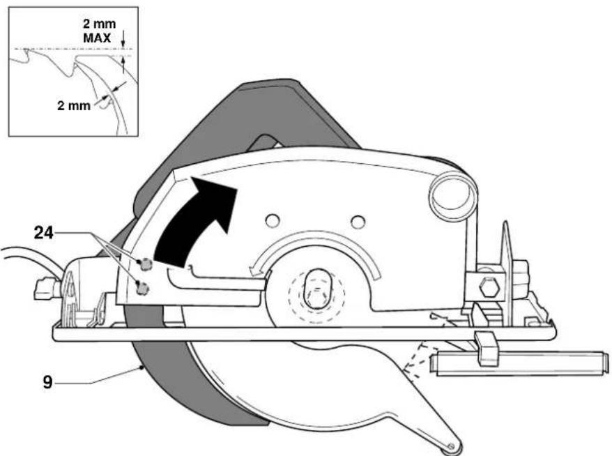
- The riving knife should be correctly set; the distance between the toothed rim and the riving knife should be 2 mm and the height difference should be 2 mm or less (fig. D).
en - 3
Checking and changing the saw blade
- Only saw blades conforming to the specifications contained in these operating instructions may be used.
- Saw blades made of high alloy, high speed steel (HSS steel) should not be used. Good results are achieved using carbide-tipped or CrV saw blades.
- Only sharp saw blades in perfect working condition should be used; cracked or bent saw blades should be discarded and replaced at once.
- Ensure that the saw blade is securely fixed and rotates in the correct direction.
Using in a fixed position
- When using a saw bench ensure that the width of the sawing gap is sufficient to take the saw blade being used.
- When cutting narrow workpieces (width less than 80 mm) longitudinally, use a rip fence guide along the longitudinal edge.
- When sawing with the workpiece clamped tight, devices should be used to prevent the workpiece kicking back.
- When sawing circular sections of wood use a device to hold the workpiece steady on both sides of the saw blade to prevent slipping.
- Ensure that pieces of wood sawn off the workpiece cannot be caught up by the teeth of the saw blade and thrown in the air.
Guard against kickback
- Kickback occurs when the saw begins to stall rapidly and is driven back towards the operator. Release the switch immediately if the blade sticks or the saw stalls.
- Keep the saw blades sharp.
- Support large panels near the cutting area.
- Use a fence or straight edge guide when ripping; do not force the tool.
- Do not remove the saw from the work during a cut while the saw blade is rotating. Release the ON/OFF-switch and wait for the saw blade to come to a halt.
Package contents
The package contains:
1 Circular Saw with 1 general purpose TCT blade
1 Parallel fence
1 Saw blade wrench
1 Instruction manual
1 Exploded drawing
- Check for damage to the tool, parts or accessories which may have occurred during transport.
• Take the time to thoroughly read and understand this manual prior to operation.
Description (fig. A)
Your DeWALT DW383 Circular Saw is a versatile Power Tool that has been designed for professional sawing of wood and plastic. Abrasive cutting wheels are available for cutting metal and stone.
1 ON/OFF-switch with lock-off device
2 Carrying handle
3 Locking lever for depth of cut
4 Motor cover
5 Front handle
6 Parallel fence
7 Blade guard
8 Blade bolt
9 Riving knife
10 Saw shoe
11 Dust extraction outlet
12 Bevel scale
13 Locking screw for bevel locking system
14 Locking screw for parallel fence
15 Mark for bevel cut
16 Mark for straight cut
17 Parallel fence scale
18 Bolt
19 Hole
20 Bracket
Electrical safety
The electric motor has been designed for one voltage only. Always check that the power supply corresponds to the voltage on the rating plate.

Your DeWALT tool is double insulated in accordance with EN 50144; therefore no earth wire is required.
Mains plug replacement (U.K. & Ireland only)
- Should your mains plug need replacing and you are competent to do this, proceed as instructed below. If you are in doubt, contact an authorized DeWALT repair agent or a qualified electrician.
- Disconnect the plug from the supply.
- Cut off the plug and dispose of it safely; a plug with bared copper conductors is dangerous if engaged in a live socket outlet.
- Only fit 13 Amperes BS1363A approved plugs fitted with the correctly rated fuse (1).
- The cable wire colours, or a letter, will be marked at the connection points of most good quality plugs. Attach the wires to their respective points in the plug (see below). Brown is for Live (L) (2) and Blue is for Neutral (N) (4).
- Before replacing the top cover of the mains plug ensure that the cable restraint (3) is holding the outer sheath of the cable firmly and that the two leads are correctly fixed at the terminal screws.
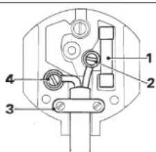
text_image
Technical diagram of a mechanical or electrical component with numbered parts labeled 1, 2, 3, and 4.
Never use a light socket.
Never connect the live (L) or neutral (N) wires to the earth pin marked E or 12
For 115 V units with a power rating exceeding 1500 W, we recommend to fit a plug to BS4343 standard.
Using an extension cable
If an extension cable is required, use an approved extension cable suitable for the power input of this tool (see technical data). The minimum conductor size is 1.5 mm^2 .
When using a cable reel, always unwind the cable completely.
ENGLISH
Also refer to the table below.
| Conductor size (mm2) Cable rating (Amperes) |
| 0.75 6 |
| 1.00 10 |
| 1.50 15 |
| 2.50 20 |
| 4.00 25 |
Cable length (m)
7.5 15 25 30 45 60
| Voltage Amperes Cable rating (Amperes) | ||||||||||
| 1 | 1 | 5 | 0 | - | 2 | . | 0 | 6 | 6 | 6 |
| 2.1 - | 3.4 | 6 | 6 | 6 | 6 | 15 | 15 | |||
| 3.5 - | 5.0 | 6 | 6 | 10 | 15 | 20 | 20 | |||
| 5.1 - | 7.0 | 10 | 10 | 15 | 20 | 20 | 25 | |||
| 7.1 - | 12.0 | 15 | 15 | 20 | 25 | 25 | - | |||
| 12.1 - | 20.0 | 20 | 20 | 25 | - | - | - | |||
| 230 | 0 - | 2.0 | 6 | 6 | 6 | 6 | 6 | 6 | 6 | |
| 2.1 - | 3.4 | 6 | 6 | 6 | 6 | 6 | 6 | 6 | ||
| 3.5 - | 5.0 | 6 | 6 | 6 | 6 | 6 | 10 | 15 | ||
| 5.1 - | 7.0 | 10 | 10 | 10 | 10 | 15 | 15 | |||
| 7.1 - | 12.0 | 15 | 15 | 15 | 15 | 20 | 20 | |||
| 12.1 - | 20.0 | 20 | 20 | 20 | 20 | 20 | 25 | - | ||
Voltage drops
Inrush currents cause short-time voltage drops. Under unfavourable power supply conditions, other equipment may be affected.
If the system impedance of the power supply is lower than 0.25 Ω, disturbances are unlikely to occur.
Assembly and adjustment

Prior to assembly and adjustment always unplug the tool.
Depth of cut adjustment (fig. A)
- Loosen the adjustment system by lifting the lever (3).
- Raise or lower the front handle (5) to set the correct depth of cut.
- Expose the blade to check the depth of cut.
- Lock the adjustment system by pushing the lever (3) down.

For optimal results, allow the saw blade to protrude from the workpiece by about 5 - 8 mm.
Mounting and adjusting the parallel fence (fig. A & E)
The parallel fence (6) is used for cutting parallel to the edge of the workpiece.
Mounting
- Insert the parallel fence (6) in the saw shoe (10) as shown.
- Insert the bolt (18) into the hole (19).
- Place the clamping bracket (20) over the bolt and tighten the locking screw (14).
6 6 1 0
Adjusting
- Slacken the locking screw (14) and set the parallel fence (6) to the desired width. The adjustment can be read on the scale (17).
- Tighten the locking screw (14).
The marks (21) and (22) can be used as a guide: mark (21): for standard steel blades
mark (22): for TCT blades
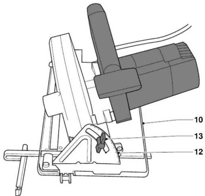
Bevel adjustment (fig. A & B)
The bevel angle can be adjusted between 0° and 45°.
- Slacken the locking screw (13).
- Set the bevel angle by tilting the saw shoe (10). The angle can be read on the bevel scale (12).
- Tighten the locking screw (13).
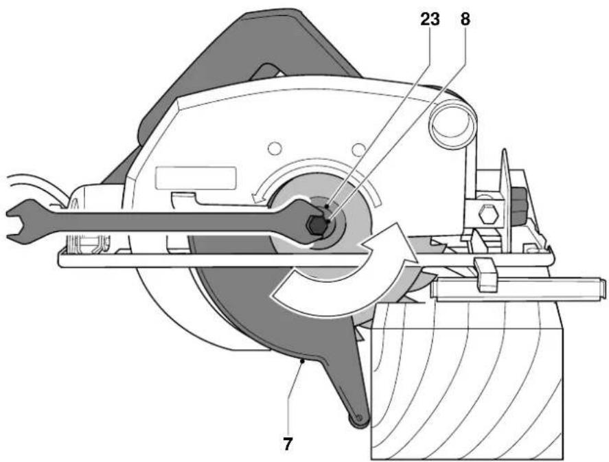
Removing and installing the saw blade (fig. C)
- Open the blade guard (7).
- Rotate the saw blade until a screwdriver can be inserted into the hole in the blade. This will prevent the blade from rotating while being loosened.
- If no screwdriver is available, or if the saw blade used does not have a hole, lock the blade by pressing the teeth into a piece of wood.
- Loosen and remove the blade bolt (8) and the outer arbour collar (23) using the wrench supplied.
- Replace the saw blade. The teeth must point in the direction of rotation, which is shown by the arrow on the upper guard housing.
- Reinstall the outer arbour collar and tighten the blade bolt (8).
en - 5
18
Adjusting the riving knife (fig. D)
For the correct adjustment of the riving knife (9), refer to the inset in figure D. Adjust the clearance of the riving knife when the saw blade is changed or whenever necessary.
- Adjust the depth of cut to 0 mm to access the clamping screws of the riving knife.
- Loosen both screws (24) and pull out the riving knife to its maximum length.
- Adjust the clearance and tighten the screws.
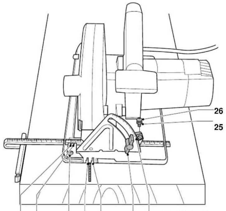
Adjusting the blade to perpendicular position (fig. E)
- Use a square to check that the blade is perpendicular to the saw shoe.
- If adjustment is required, slacken the nut (25) of the stop (26) and locking screw (13).
- Adjust the blade until the pointer (27) reads exactly 0^ and tighten the nut (25) and the locking screw (13).
Adjusting the cutting line marks (fig. E)
The marks for bevel cuts (15) and for straight cuts (16) have two grooves each:
narrow groove: for centering standard steel blades wider groove: for centering TCT blades
To adjust, proceed as follows:
- With the blade locked at 90^ , make a trial cut of approx. 400 mm.
- Withdraw the saw slightly.
- Slacken the screw (28) and align the cut and the mark (16).
• Firmly tighten the screw (28).
Both cutting line marks are now correctly adjusted.
Instructions for use

• Always observe the safety instructions and applicable regulations.
- Ensure the material to be sawn is secured in place.
- Apply only a gentle pressure to the tool and do not exert side pressure on the saw blade.
- Avoid overloading
- Do not use your saw for pocket cuts.
Prior to operation:
- Make sure the guards have been mounted correctly. The saw blade guard must be in closed position.
- Make sure the saw blade rotates in the direction of the arrow on the blade.
Switching ON and OFF (fig. A)
For safety reasons the ON/OFF-switch (1) of your Circular Saw is equipped with a lock-off device.
- Slide the ON/OFF-switch (1) backwards to unlock the tool.
- To run the tool, press the ON/OFF-switch. As soon as the ON/OFF-switch is released the lock-off device is automatically activated to prevent unintended starting of the machine.

Do not switch the tool ON or OFF when the saw blade touches the workpiece or other materials.
Holding the Circular Saw (fig. A)
- Hold your DeWALT Power Tool by the main grip and the front handle (5) to guide the saw properly.
- The cut being smoother at the side where the saw blade leaves the workpiece, clamp it with the back facing the saw blade.
- Follow the line drawn on the workpiece using the mark (16) and lead the cord away in line with the rear of the tool.
- In case of a bevel angle of 45^ follow the line drawn on the workpiece using the mark (15).

Dust extraction (fig. A)
Your DEWALT Circular Saw is fitted with a dust extraction outlet (11).
- Whenever possible, connect a dust extraction device designed in accordance with the relevant regulations regarding dust emission.
•Vacuum hoses of most common vacuum cleaners will fit directly into the dust extraction outlet.
Consult your dealer for further information on the appropriate accessories.


ENGLISH
Maintenance
Your DeWALT Power Tool has been designed to operate over a long period of time with a minimum of maintenance. Continuous satisfactory operation depends upon proper tool care and regular cleaning.

Lubrication
Your Power Tool requires no additional lubrication.

Cleaning
Keep the ventilation slots clear and regularly clean the housing with a soft cloth.

Unwanted tools and the environment
Take your tool to an authorized DEWALT repair agent where it will be disposed of in an environmentally safe way.
GUARANTEE
- 30 DAY NO RISK SATISFACTION GUARANTEE If you are not completely satisfied with the performance of your DeWALT tool, simply return it within 30 days, complete as purchased, to a participating Dealer, or an authorized DeWALT repair agent, for a full refund or exchange. Proof of purchase must be produced
• ONE YEAR FREE SERVICE CONTRACT •
If you need maintenance or service for your DeWALT tool, in the 12 months following purchase, it will be undertaken free of charge at an authorized DeWALT repair agent. Proof of purchase must be produced. Includes labour and spare parts for Power Tools. Excludes accessories.
• ONE YEAR FULL WARRANTY •
If your DeWALT product becomes defective due to faulty materials or workmanship within 12 months from the date of purchase, we guarantee to replace all defective parts free of charge or, at our discretion, replace the unit free of charge provided that:
• The product has not been misused.
• Repairs have not been attempted by unauthorized persons.
• Proof of purchase date is produced.
This guarantee is offered as an extra benefit and is additional to consumers statutory rights.
For the location of your nearest authorized DeWALT repair agent, please use the appropriate telephone number on the back of this manual.
en - 7
SIERRA CIRCULAR DW383
¡Enhorabuena!
Director Engineering and Product Development Horst Großmann

text_image
X. fopsmannL'emballage contient:
Director Engineering and Product Development Horst Großmann

text_image
H. JopsmannDeWALT, Richard-Klinger-Straße 40, D-65510, Idstein, Duitsland
nl - 1
42
Director Engineering and Product Development Horst Großmann

text_image
X. fopsmannDeWALT, Richard-Klinger-Straße 40, D-65510, Idstein, Tyskland
49
no - 1
NORSK
Sikkerhetsforskrifter
Director Engineering and Product Development Horst Großmann

text_image
X. fopsmannDeWALT, Richard-Klinger-Straße 40, D-65510, Idstein, Alemanha
55
pt - 1
PORTUGUÊS
15 Tire as chaves de aperto
Montagem e ajuste da guia paralela (fig. A & E) The parallel fence (6) is used for cutting parallel to the edge of the workpiece.
Montagem
Director Engineering and Product Development Horst Großmann

text_image
X. fopsmannDirector Engineering and Product Development Horst Großmann

text_image
X. fopsmannDeWALT, Richard-Klinger-Straße 40, D-65510, Idstein, Tyskland
sv - 1
68
Säkerhetsinstruktioner
| DW383 | ||
| L_pA (ses siddeti) | dB(A)* | 94,0 |
| L_t/A (akustik gücü) | dB(A) | 102,0 |