T611 - Treadmills SportsArt - Free user manual and instructions
Find the device manual for free T611 SportsArt in PDF.

User questions about T611 SportsArt
0 question about this device. Answer the ones you know or ask your own.
Ask a new question about this device
Download the instructions for your Treadmills in PDF format for free! Find your manual T611 - SportsArt and take your electronic device back in hand. On this page are published all the documents necessary for the use of your device. T611 by SportsArt.
USER MANUAL T611 SportsArt
SPORTSART T611 TREADMILL
TABLE OF CONTENTS
-
INTRODUCTION.... 1
INTRODUCTION. Specifications.... 2 -
SAFETY PRECAUTIONS.... 3
-
LIST OF PARTS.... 8
-
ASSEMBLING THE PRODUCT.... 10
STEP 0 Remove Packaging Material.... 11
STEP 1 Install the Pedestals.... 13
STEP 2 Install.the.Display.... 20
STEP 3 Move.the.Treadmill.... 23
STEP 4 Level.the.Treadmill.... 24
STEP 5 Install.the.Power.Cord.... 25
STEP 6 Align.the.Walk.Belt.... 26
STEP 7 Adjust Walk Belt Tightness.... 27
STEP 8 Safety.Key.Cord.Installation.... 28
- UNDERSTANDING THE T611 DISPLAY CONSOLE
DISPLAY Overview.... 30
DISPLAY Windows.... 31
DISPLAY Keys.... 32
- OTRIEDATING THE T611
OPERATION Quick Start.... 34
OPERATION User.I.D.Selection 34
OPERATION Workout Settings 35
OPERATION Workout Programs.... 35
OPERATION User Parameter Settings.... 39
- ABOUT HEART RATE DETECTION AND PRESENTATION
HEART RATE Telemetry....41
HEART RATE Contact.... 41
- GUIDELINES FOR EXERCISE
HOW HARD SHOULD I EXERCISE? 43
HOW LONG SHOULD I EXERCISE? 43
HOW OFTEN SHOULD I EXERCISE? 43
- MAINTENANCE
MAINTENANCE Error Messages.... 44
MAINTENANCE Fuse Replacement.... 45
MAINTENANCE Lubrication 46
MAINTENANCE Lubrication Prompt.... 46
MAINTENANCE Lubrication Procedure 47
MAINTENANCE Check List.... 50
MAINTENACE One-Year Maintenance Log....52
10.BLOCK DIAGRAM....53
1. INTRODUCTION
Thank you for purchasing a high quality product from SportsArt Fitness. Constructed of robust materials and built for years of trouble-free usage, the SportsArt T611 Treadmill was designed and manufactured to become an integral part of your fitness regimen. This product is a unique tool made to help you obtain your fitness goals. But like every tool, it must be used properly. Please read and abide by instructions in this manual. Understanding the correct use of this equipment will help you achieve your exercise goals safely and effectively.
text_image
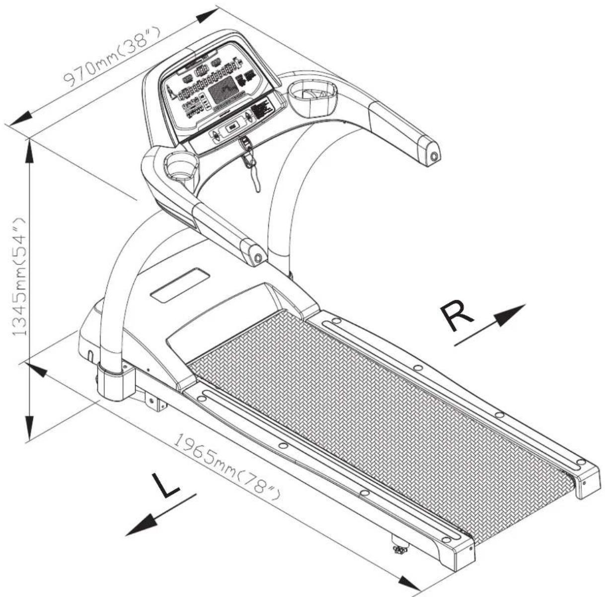
970mm(38") 1345mm(54") 1965mm(78") RINTRODUCTION Specifications
T611 Product Specifications
Speed range: 0.1 to 12.0 mph; 0.2 to 20 kph
Incline range: 0 to 15%
Motor: 3 hp
Display type: LED
Running surface: 20 x 58 inches; 508 x 1473 mm
Workout programs: Programmable interval, random, hill (x3), glute (30-minute and 45-minute programs), quick start, manual/track
Heart rate control programs: weight loss, cardio conditioning, ZoneTrainer™
Feedback: Calories, distance, speed, incline, time, calories per hour, METs, pace, actual heart rate, weight loss target heart rate, cardio target heart rate, ActivZone™
Maximum user weight: 400 lb., 180 kg
Product dimensions: 77.5 x 38 x 53 inches; 1965 x 970 x 1345 mm
Product weight: 229 lb.; 503 kg
Fuse: (120V) 15 A (slow); (220V) 10 A (slow)
2. SAFETY PRECAUTIONS
Your SportsArt treadmill was designed and built for optimum safety. However certain precautions apply whenever you use your treadmill.
Please read the entire manual before assembly and operation. Also, please note the following safety precautions:
IMPORTANT SAFETY PRECAUTIONS
- Please read the instructions carefully and install the treadmill as instructed.
- Assemble and operate the treadmill on a solid, level surface. DO NOT use outdoors or near water.
- Never allow children on or near the treadmill.
- Check the treadmill before every use. Make sure all parts are assembled, and all fasteners are tightened. DO NOT use the treadmill if the unit is disassembled in any way.
- Keep your hands away from moving parts.
- Wear proper workout clothing; DO NOT wear loose clothing. DO NOT wear shoes with leather soles or high heels. Tie all long hair back. Do not go barefoot on this product.
- Be careful when mounting and dismounting the unit.
- The walk belt will not stop immediately if any object becomes caught in the belts or rollers.
- DO NOT use accessories that are not specifically recommended by the manufacturer. Such parts might cause injuries or cause the unit to fail.
- Unplug from outlet before servicing or removing of any parts.
- Close supervision is necessary when this treadmill is used by, or near children, invalids, or disabled persons.
- Use this treadmill only for its intended use as described in this manual.
- Never operate this treadmill if it has been damaged in any way. If it is not working properly, or has been dropped or damaged, contact your dealer.
- DO NOT carry this treadmill by the power cord or use the cord as a handle.
- Keep the power cord away from heated surfaces.
-
Keep all air ventilation areas free of blockage.
-
Never drop or insert any object into any opening.
- DO NOT operate where aerosol (spray) products are being used or where oxygen is being administered.
• The user weight limit for this treadmill is 180 kg (400 lb.).
Note that the top speed setting of 12 mph (20 kph) is suitable for users of up to 125 kg (275 lb.). Note also that speed may automatically decrease to avoid the overload of electronic components.
- Product performance depends on adequate power supply. Each light commercial treadmill requires one 15-Amp (for 110 V areas) or one 10-Amp (for 220 V areas) dedicated circuit for proper operation.
- This treadmill is not intended for use by persons (including children) with reduced physical, sensory or mental capabilities, or lack of experience and knowledge, unless they have been given supervision or instruction concerning use of the treadmill by a person responsible for their safety.
• Children should be supervised to ensure that they do not play with the treadmill.
- Treadmills should be positioned away from walls to avoid injury due to falls. Be sure that the back of the treadmill has at least six to seven feet of clearance from a ledge, wall or window. The power supply and wiring should be located away from walking paths or taped to prevent tripping when stepping on or off of the running belt.
CAUTION
If you feel any pain or abnormal sensation, STOP YOUR WORKOUT and consult you physician immediately. Work within your recommended exercise level. DO NOT work to exhaustion.
Before beginning any exercise program, you should consult with your doctor. It is recommended that you undergo a complete physical examination.
DO NOT stand on the walk belt when starting the treadmill. Straddle the belt with one foot on each landing strip.
To prevent injury, stand on landing strips (side rails) before starting the treadmill.
To reduce the risk of electric shock, unplug this treadmill from the electrical outlet immediately after use and before cleaning it or removing covers.
Improper grounding can increase the risk of electric shock. Check with a qualified technician if you are in doubt as to whether the treadmill is properly grounded. DO NOT modify the plug provided with the product; If the plug does not fit the outlet, have the proper outlet installed by a qualified technician.
Always use the safety key when operating the treadmill.
Note: This equipment has been tested and found to comply with the limits for a Class B digital device, pursuant to part 15 of the FCC Rules. These limits are designed to provide reasonable protection against harmful interference in a residential installation. This equipment generates, uses and can radiate radio frequency energy and, if not installed and used in accordance with the instructions, may cause harmful interference to radio communications. However, there is no guarantee that interference will not occur in a particular installation.
The expense to correct such interference must be borne by the product owner or operator.
WARNINGS AND CAUTIONS(FRENCH)
text_image
Technical diagram of a treadmill with labeled parts including control panel, airbags, and battery pack| Assembly Parts | |||||
| No. | Name Qty | No. | QtyDescription | ||
| A1 | Display | 1 | A9 | Hardware kit | 1 |
| A2 | Cowling/handlebars | 1 | A10 | Power cord | 1 |
| A3 | Right pedestal | 1 | A11 | Lube applicator tube | 1 |
| A4 | Feeder cord | 1 | Lubricant | 4 | |
| A5 | Pedestal cover | 2 | |||
| A6 | Body | 1 | |||
| A7 | Left pedestal | 1 | |||
| A8 | Owner's manual | 1 | |||
A hardware kit is provided in the packaging of this product. Please inspect the hardware kit for the following items.
| Parts in the Hardware Kit | ||||
| No. | Name | Qty | NotesSpecification | |
| 21 | Screw cap (flat) | 2 | ||
| 22 | Screw cap (curved) | 2 | ||
| 23 | Safety key | 1 | ||
| T-shaped Allen wrench | 1 | M6 | ||
| T-shaped Allen wrench | 1 | M4 | ||
| L-shaped Allen wrench | 1 | M5 | ||
| Phillips head tool | 1 | |||
| Fuse | 1 | 110V-15A | ||
| 220V-10A | ||||
If you discover items missing or damaged in shipping, please contact the SportsArt Service Department. Keep the hardware kit in a secure place for future use. Tools may be needed to disassemble the product in preparation for moving or other activities.
Some components are installed on the product. These items will be needed for product assembly.
| Parts on the Product | |||
| No. | Name | Specification | |
| 31 | Serrated washer | D18*d8.5*t2.0*19T | |
| Mushroom top inner hex screw | M8*P1.25*L20 | ||
| 32 | Serrated washer (curved) | D18*d8.5*t2.0 | |
| Mushroom top inner hex screw | M8*P1.25*L20 | ||
| 33 | Mushroom top inner hex screw | M5*0.8*L12 | |
| 34 | Phillips screw | M4*P0.7*L10 | |
4. ASSEMBLING THE PRODUCT
Please follow instructions below to assemble this treadmill. Note: For brevity, throughout this manual, the word "screws" is used where screws, washers, and other hardware may be involved. Also, the words "left" and "right" are used in reference to the product and its parts. Note that, as such, these designations correspond to the left and right sides of a person in position to exercise on the product. Also note that some parts are marked "L" for left or "R" for right.
This product is designed for assembly by one person. But in some cases, depending on personal strength and experience, two people may be needed for product assembly. Get help if you need it, and plan for a safe assembly and product operation by considering the following:
- The site. Do not install this product in an area of high humidity. Exposure to extensive water vapor, chlorine, bromine, ammonia, and other chemicals can damage the product and present a hazard to exercisers.
- The surface. A solid, level surface is required for proper operation of this product.
- The space. Allow enough space around the product for safe mounting and dismounting.
- Electrical issues. Make sure that the actual power supply matches product specifications. Be aware that some components maintain an electric charge even after the power supply has been disconnected. Turn off the product, wait five minutes, and unplug the product before removing covers. Before moving the product, tuck the power cord out of the way to avoid running over it.
Not abiding by instructions in this manual can present a hazard to people and the product.
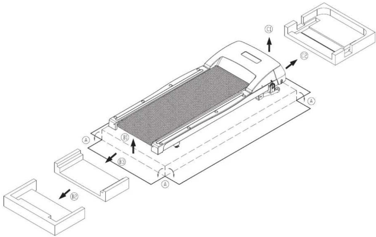
STEP 0 Remove Packaging Material
Follow steps A, B, and C to prepare the product for assembly.
A. Remove the packaging material. Then cut the box flaps to lay them flat on the ground.
B. Lift the rear of the treadmill to remove packaging material in the rear and center of the box.
C. Lift the front of the treadmill to remove packaging material at the front of the treadmill.
text_image
Technical diagram of a vehicle chassis with labeled components and assembly stepsMake sure that the walk belt is in the correct position in relation to both walk belt guides. The guides should press the sides of the walk belt downward, away from the treadmill body, as in the image marked √ The image marked X shows the incorrect position; the side of the walk belt is pressed upward, toward the treadmill body. If the walk belt is in the incorrect position, turn roller adjustment screws in position A counterclockwise until the sides of the belt can be placed in the correct position. Then follow step 6 to adjust walk belt tension.

text_image
Technical diagram of a device's internal structure with labeled parts and inspection annotations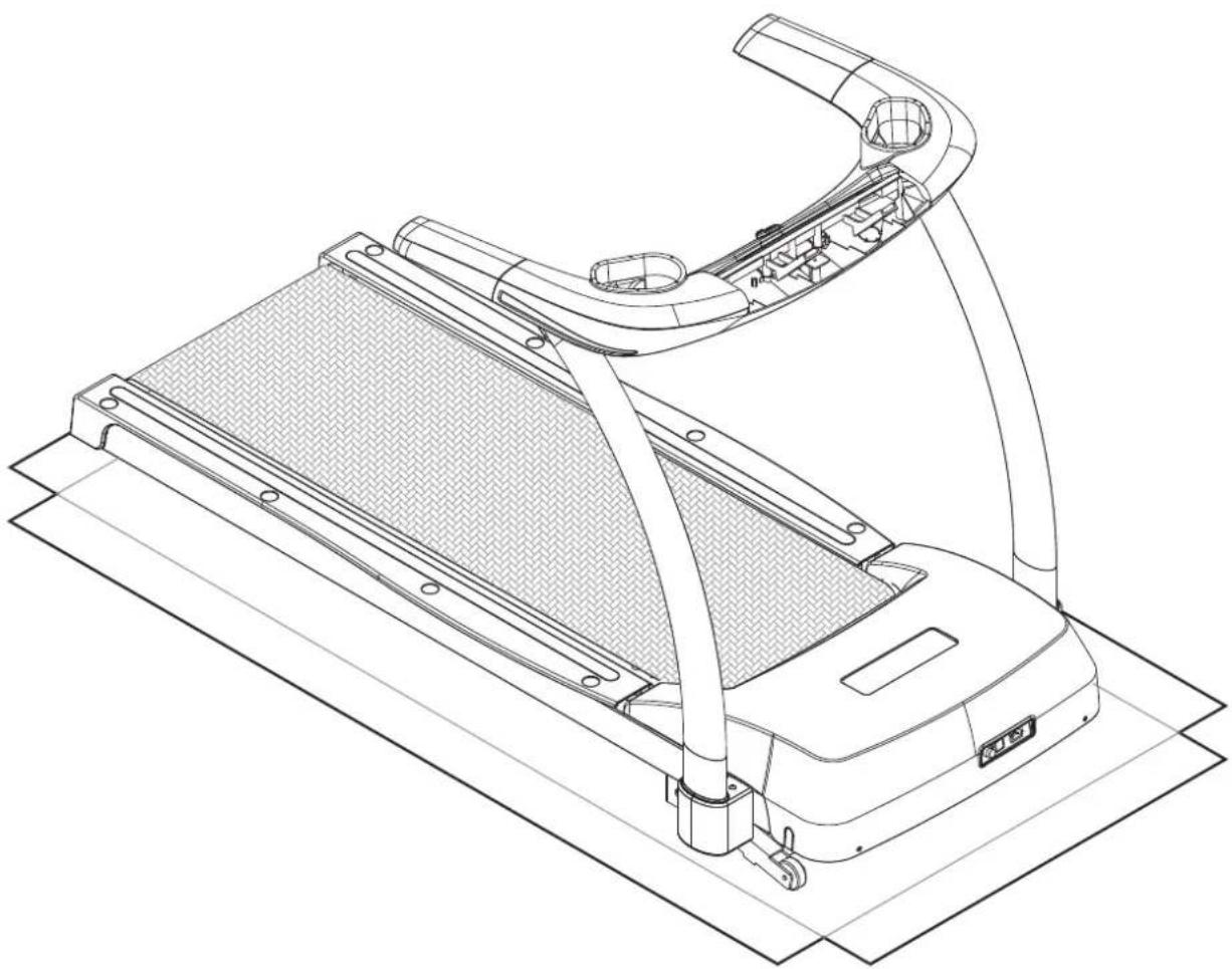
natural_image
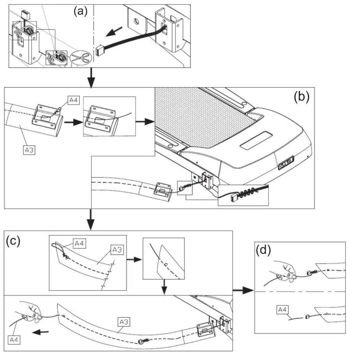
Technical line drawing of a treadmill with handle and seat assembly (no text or symbols)1-1. Remove screws (80) in the left and right pedestal bases. Remove screws (33) from the left and right pedestals (A7, A3)
text_image
Technical diagram of a car interior with labeled parts and directional arrows indicating assembly or movement
text_image
A7 A3 331-2. Fboread steplate darbleight(d)the right pedestal (A3).
(a) First, cut the zip tie that secures the data cable to the right pedestal base. Then Pull the data cable through the hole as shown.
(b) Place the right pedestal (A3) flat on the ground with its bottom part facing the data cable. Untie the feeder cord (A4) from the lower part of the pedestal. Tie the feeder cord (A4) onto the end of the data cable.
(c) Untie the feeder cord (A4) from the top of the right pedestal (A3). Then, from the top of the pedestal, pull the feeder cord, thus threading the data cable through the pedestal.
(d) After the data cable is threaded through the pedestal, untie the feeder cord (A4) from the data cable.
flowchart
graph TD
    A["(a)"] --> B["Switching cable"]
    B --> C["Internal circuit"]
    C --> D["Component 1: Cable connector"]
    D --> E["Component 2: Cable connector"]
    E --> F["Component 3: Cable connector"]
    F --> G["Component 4: Cable connector"]
    G --> H["Final terminal connection"]

    subgraph (a)
        I["Switch"] --> J["Coiled cable"]
        J --> K["Switch"]
        K --> L["Switch"]
        L --> M["Switch"]
        M --> N["Switch"]
        N --> O["Switch"]
        O --> P["Switch"]
        P --> Q["Switch"]
        Q --> R["Switch"]
    end

    subgraph (b)
        S["A3"] --> T["A4"]
        T --> U["Internal cable"]
        U --> V["Internal cable"]
        V --> W["Internal cable"]
        W --> X["Internal cable"]
        X --> Y["Internal cable"]
        Y --> Z["Internal cable"]
        Z --> AA["Internal cable"]
    end

    subgraph (c)
        AB["A4"] --> AC["A3"]
        AC --> AD["Internal cable"]
        AD --> AE["Internal cable"]
        AE --> AF["Internal cable"]
        AF --> AG["Internal cable"]
        AG --> AH["Internal cable"]
        AH --> AI["Internal cable"]
        AI --> AJ["Internal cable"]
    end

    subgraph (d)
        AK["A4"] --> AL["A4"]
        AL --> AM["Internal cable"]
        AM --> AN["Internal cable"]
        AN --> AO["Internal cable"]
        AO --> AP["Internal cable"]
        AP --> AQ["Internal cable"]
        AQ --> AR["Internal cable"]
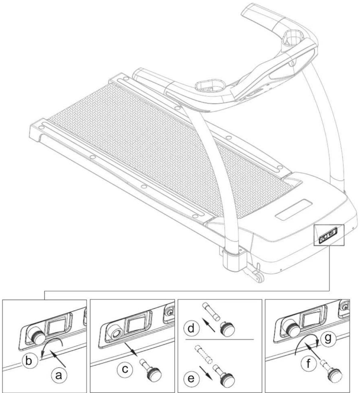
1-3. After threading the data cable into the right pedestal, follow the steps below to secure the pedestals.
(a) Insert pedestal base covers (A5) separately onto the left and right pedestals (A7, A3).
(b) Insert the right pedestal (A3) onto the right pedestal base. Insert the left pedestal

text_image
(a) A3 A5 A7
text_image
A3 A7 (b)1-4. Hand-tighten screws (31) on both left and right pedestals (A7, uA8) not fully secure these screws yet.

text_image
A3 A7 311-5. Follow steps (a) through (g) to assemble the cowling/handlebar assembly.
(a) First, remove screws (31), (32) from the cowling/handlebar assembly (A2).
(b) Set one side of the cowling/handlebar assembly onto the left pedestal (A7).
(c) Connect the data cable (A3) in the right pedestal to the cable (A2) in the cowling/handlebar assembly.

text_image
(a) A2 32 31 ③2 ③1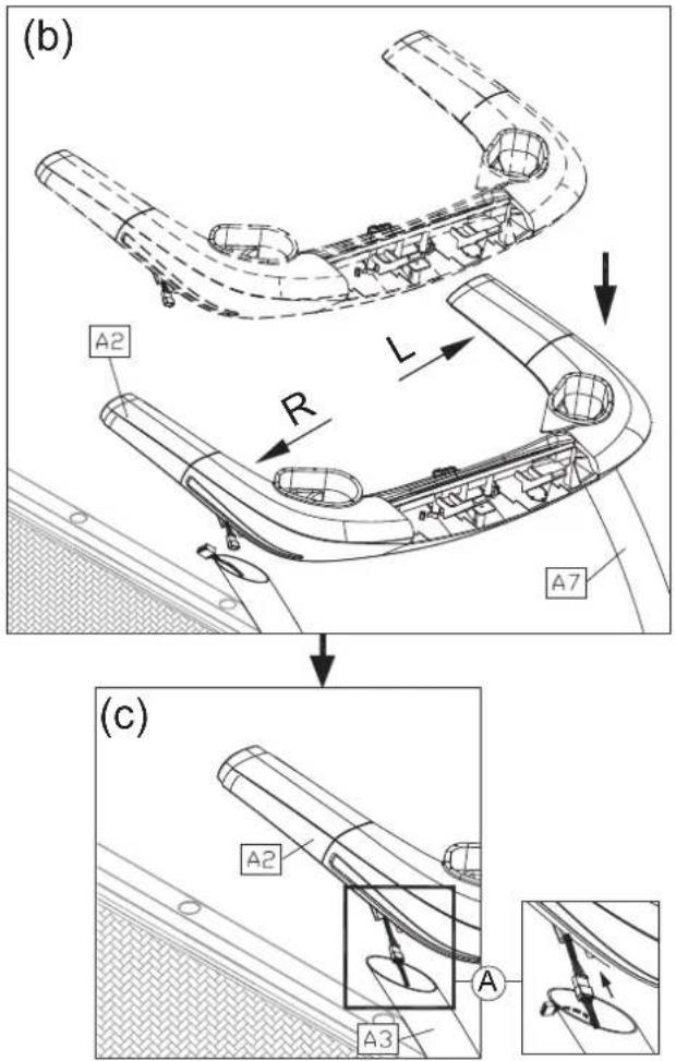
text_image
(b) A2 R L A7 (c) A2 A A3(d) Tuck the data cable into the pedestal. Then insert the right side of the handlebar into the right pedestal (A3).
(e) Loosely secure handlebar screws (31)(32), but do not fully secure these screws. First secure pedestal base screws (see step 1-4). Then secure screws (32) in area B. Then secure screws (31) in area C.
(f) Insert the screw covers (21)(22) into the screw heads.
(g) Finally, push pedestal base covers (A5) into place and secure them with screws (33).

text_image
Technical diagram showing a mechanical assembly with labeled components and an inset image of a light bulb.
natural_image
Line drawing of a treadmill with control panel and mesh tray (no text or symbols)Follow steps (instalboughdig) lay.
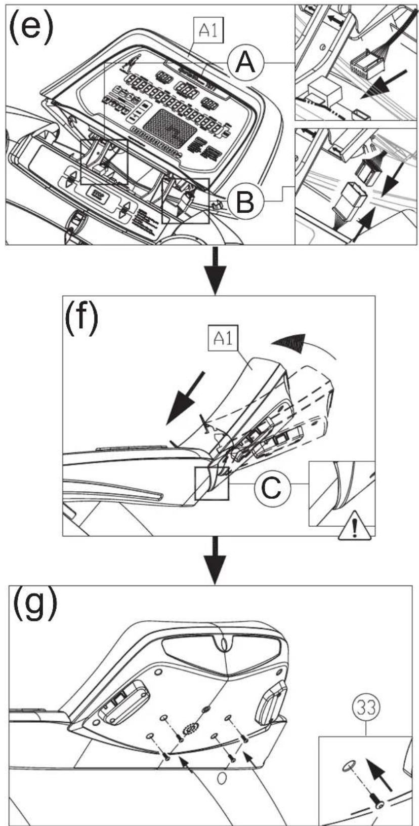
(a) First, remove display connection screws (33) from the cowling/handlebar assembly (A2).
(b) To avoid damaging the display, insert the display (A1), as indicated by the arrows, onto the cowling/handlebar assembly (A2).
(c) Then, tilt the display (A1) slightly.
(d) Temporarily secure the display by asserting pressure as indicated by the arrows.

flowchart
graph TD
    A["(a)"] --> B["Assembly of car air"]
    B --> C["Part 33"]
    C --> D["Assembly of air valve"]
    D --> E["(b)"]
    E --> F["Assembly of air vent"]
    F --> G["Part B"]
    G --> H["Assembly of air tank"]
    H --> I["(c)"]
    I --> J["Assembly of air valve"]
    J --> K["(d)"]
(e) Connect cables in positions A and B.
(f) After connecting cables, tuck them away safely. Then slightly lift the display (A1) and press it into place. Make sure that the plastic of the display lower cover rests on the outside of the cowling/handlebar assembly plastic.
(g) Use screws (33) to secure the display (A1).
text_image
(e) A1 A B (f) A1 C (g) ③3STEP 3 Move the Treadmill
Please follow steps (a), (b), and (c) to put the to put the treadmill in place for use.
(a) From the back of the treadmill, grip the frame with both hands. Then lift and push.
(b) With the front of the treadmill slanted downward, use the front transport wheels to roll the unit.
(c) Push the unit into place for use.
(a)

natural_image
Technical line drawing of a treadmill with an inset showing internal components (no text or symbols)(b)

natural_image
Technical line drawing of a mechanical lever system with curved arm and pivot (no text or symbols)(c)

natural_image
Diagram showing a treadmill being processed, with no visible text or symbolsSTEP 4 Level the Treadmill
4-1. Push down on the end of the treadmill. Inspect whether levelers touch the ground evenly.
4-2. If the unit does not sit flat on the floor, follow steps (a), (b), and (c) to level the unit.
(a) Rotate the leveler nut downward.
(b) Rotate the leveler foot downward so it presses the floor.
(c) Secure the leveler nut upward against the frame to secure this position.

text_image
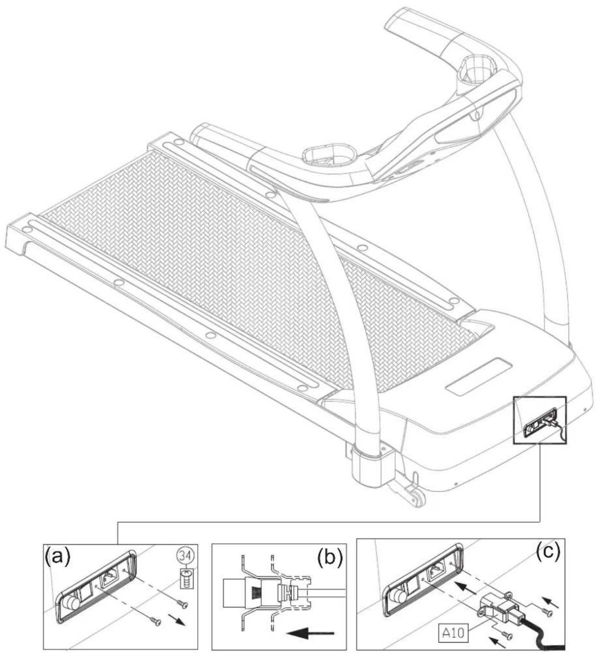
transport wheel (A) A space B transport wheel (B) ✓ × (a) (b) (c)STEP 5 Install the Power Cord
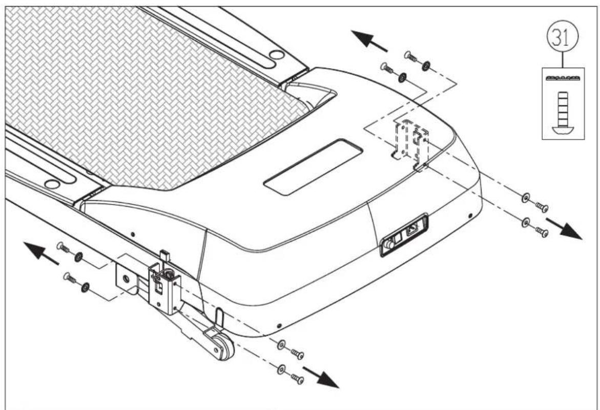
Please follow instructions below to install the power cord onto the treadmill.
(a) First, remove screws (34) from the power cord connector.
(b) Insert the end of the power cord into the connector on the product.
(c) Secure the power cord screws (34) as shown (c). Insert the other end of the power cord into an appropriate wall power outlet.
(d) The power switch on the product has two sides, one marked “-” and the other marked “o”. Turn on the product by pressing the “-” side of the switch. Turn off the product by pressing the “o” side of the switch.
text_image
Technical diagram of a treadmill device with labeled components and exploded views (a, b, c)STEP 6 Align the Walk Belt
The treadmill walk belt should rotate in the center of the deck, with equal spacing on both sides. If the walk belt tends to be a closed to screw side that
side clockwise no more than 1/4 turn. This extends that side of the rear roller toward the back, pushing the walk belt toward the other side.

text_image
Technical line drawing of a treadmill with labeled components and a cross-sectional view showing A = B area.STEP 7 Adjust Walk Belt Tightness
If the walk belt seems to pause during use, the walk belt may be too loose. Stop using the treadmill and inspect walk belt tightness. At the center of the walk belt length, grasp both sides of the walk belt as shown in illustration (A) and (B). You should be able to lift the walk belt 30 mm (1 1/8 inch) or to 3 kg (6.6 lb.) of pressure. If the walk belt is too loose, rotate both rear roller adjustment screws clockwise 1/4 turn at a time. And inspect the belt tightness. Repeat the same procedure until the walk belt tightness is just right. But do not over-tighten the walk belt. If the walk belt is too tight, turn rear roller adjustment screws on both sides counterclockwise 1/2 turn at a time.
Note: Finger guard placement should be secured at a distance of 2 mm from the rear roller. If the distance exceeds 6 mm, adjust finger guard placement by removing both left and right landing strips, loosening finger guard screws and sliding finger guards into the proper position. Secure finger guard screws in the position shown in figure C. For more information, please refer to lubrication instructions.
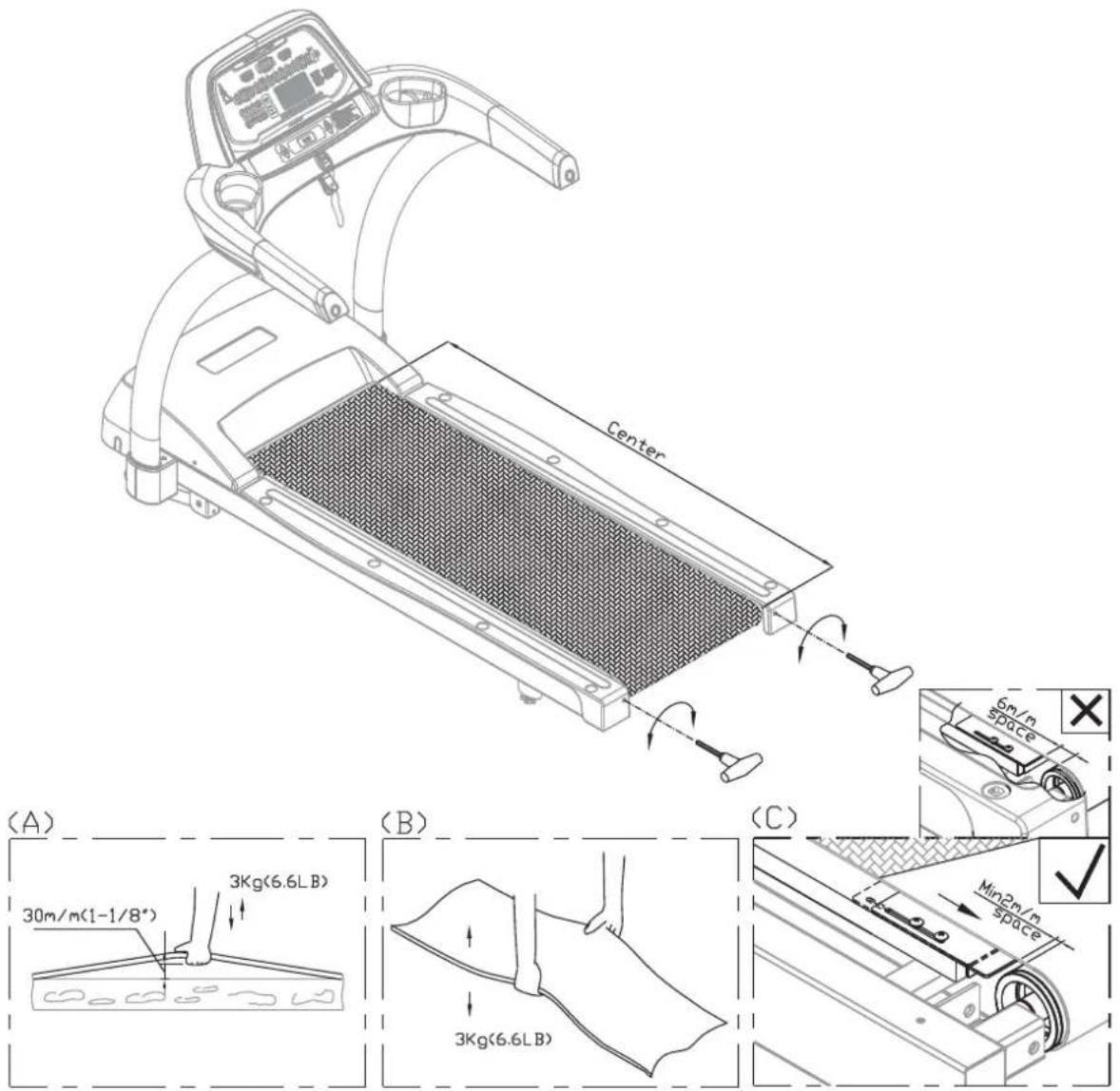
text_image
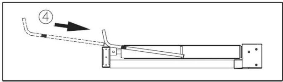
Center 30m/m(1-1/8") 3Kg(6.6LB) 3Kg(6.6LB) 6m/m space Min2m/m space (A) (B) (C)STEP 8 Safety Key Cord Installation
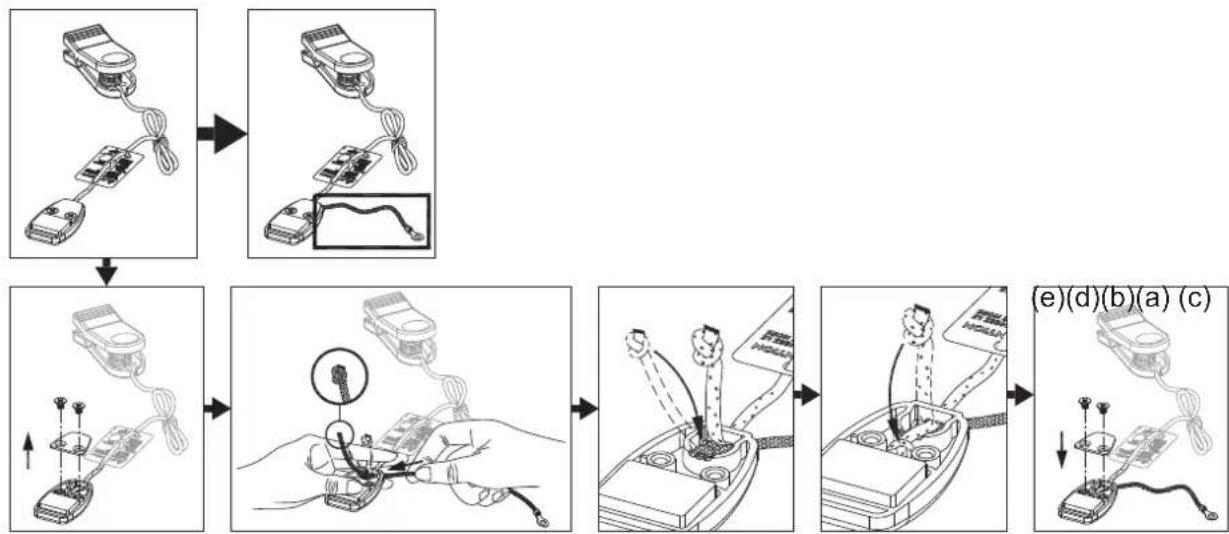
For home use, do not secure the safety key onto the product. Safety regulations require that the safety key be detachable to prevent unsupervised product use of the treadmill by children.
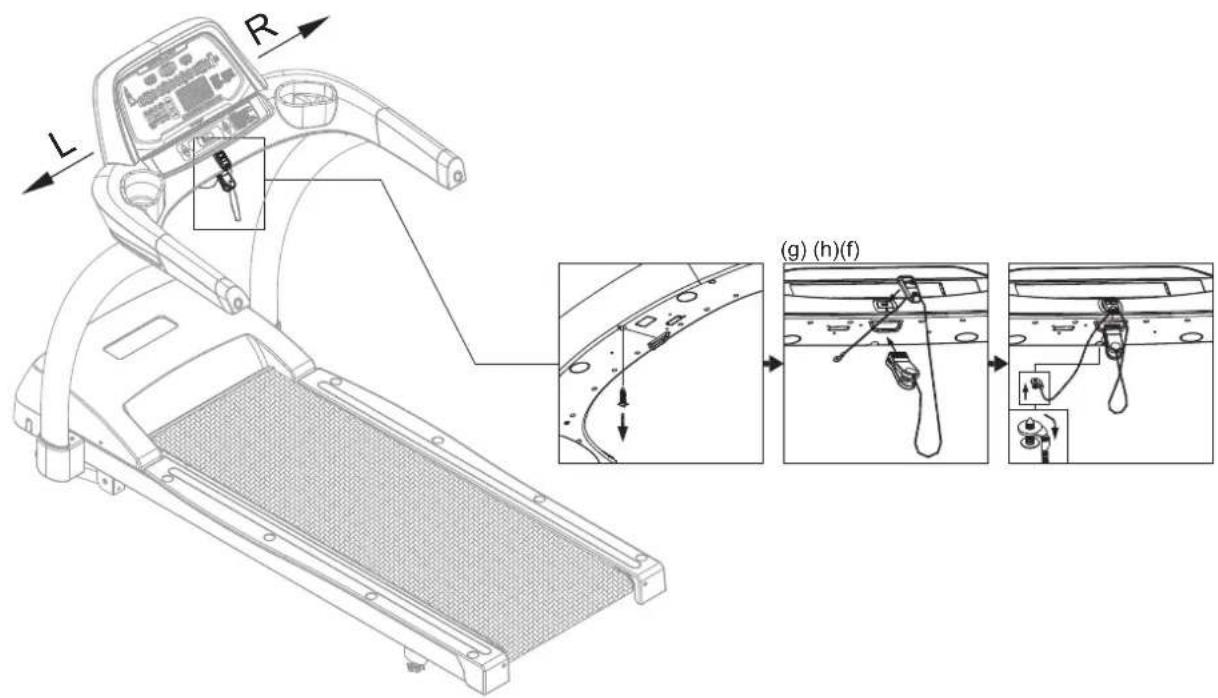
For light commercial use, the safety key can be secured to the treadmill to prevent the key from being removed and lost. To do so, follow instructions in steps (a)-(e) on this page and (f)-(h) on the following page.
(a) Use a Phillips screwdriver to remove screws from the safety key magnet case.
(b) Insert the safety key cord into the hole. Tie a knot in the end of the cord.
(c) Insert the knot as shown into the cavity of the plastic case.
(d) Put the other cord on top of the safety key cord as shown. Make sure cords are between the screw holes.
(e) Secure the cover and screws.
Note: Screws must fit flat against the cover.
flowchart
graph TD
    A["Sensor Input"] --> B["Measurement Cable"]
    B --> C["Measurement Cable with Cable"]
    C --> D["Measurement Cable with Cable"]
    D --> E["Measurement Cable with Cable"]
    E --> F["Measurement Cable with Cable"]
    F --> G["Terminal Connection"]
    G --> H["Terminal Connection"]
    style A fill:#f9f,stroke:#333
    style B fill:#f9f,stroke:#333
    style C fill:#f9f,stroke:#333
    style D fill:#f9f,stroke:#333
    style E fill:#f9f,stroke:#333
    style F fill:#f9f,stroke:#333
    style G fill:#f9f,stroke:#333
    style H fill:#f9f,stroke:#333
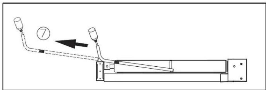
Secure the safety key to the treadmill as follows in steps (f)-(h)
(f) Remove one screw on the left as shown.
(g) Put the safety key in its place.
(h) Insert the screw back into the loop. Secure the screw back into place. Bend the loop downward 90^ .
Note: The cord should extend from the loop, facing the user.
text_image
Technical diagram of a treadmill with labeled parts and exploded view showing internal components and adjustment stepsNote: The safety key should not be secured to the product if there is a risk that children or anyone else might operate the product in an unsafe manner. To prevent the unsafe operation of this product, adults in homes should remove the safety key and unplug the treadmill after use. In light commercial settings, all possible precautions must be taken to prevent unsafe use of this product.
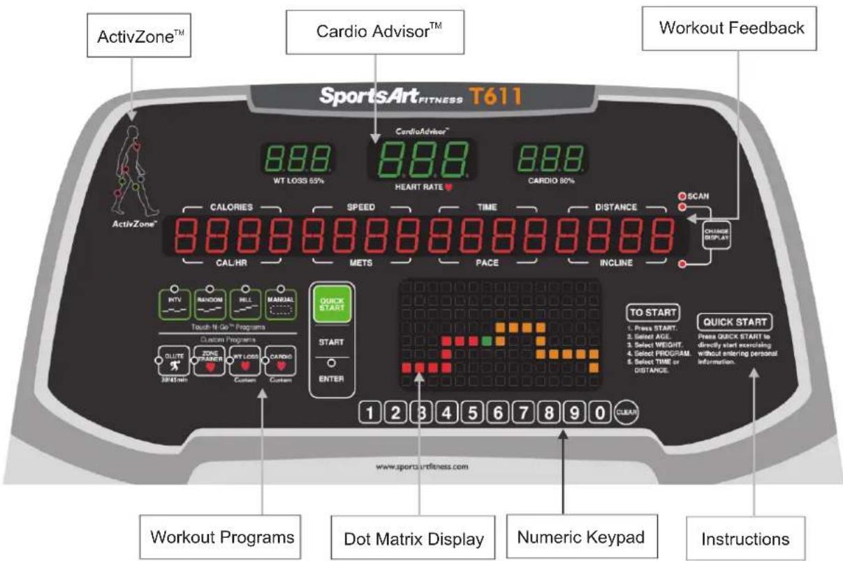
5. UNDERSTANDING THE T611 DISPLAY CONSOLE
v
The T611 treadmill is designed for user convenience. With better feedback about your workout, you get better results. The following explains the display window and key functions. Please read this manual, understand the display functions, and thereby get optimum enjoyment and benefit from this product.
text_image
ActivZone™ Cardio Advisor™ Workout Feedback SportsArt_FITNESS T611 8.88. WT LOSS 65% 8.88. HEART RATE ♥ 8.88. CARDIO 80% 8.88. CALORIES SPEED TIME DISTANCE SCAN CAL/HR METS PACE INCLINE CHANGE DISPLAY RDTV RANDOM HELL MANUAL QUICK START TO START 1. Press START. 2. Select AGE. 3. Select WEIGHT. 4. Select PROGRAM. 5. Select TIME or DISTANCE. QUICK START Press QUICK START to directly start exercising without entering personal information. QUICK START To Start 1. Press START. 2. Select AGE. 3. Select WEIGHT. 4. Select PROGRAM. 5. Select TIME or DISTANCE. QUICK START QUICK START www.sportsartfitness.com Workout Programs Dot Matrix Display Numeric Keypad Instructions
text_image
INCLINE STOP HOLD TO REBEET SPEED CAUTION - Keep hands and clothing away from moving parts. - Do not let children on or near the product. - Risk of injury to persons - to avoid injury, stand on the side to begin starting tomorrow. - Stop tooosing if you feel hurt or dirty. - Read instruction manual before using - To reduce the risk of injury from moving parts, unplug before servicing. - To reduce the risk of electric shock, unplug before cleaning or lifelong.CardioAdvisor™ helps you maintain a workout heart rate to meet your fitness goals.
65% HR TARGET shows the optimum heart rate zone for weight loss workouts.
■ HEART RATE shows the actual heart rate. Range: 40 to 250 beats per minute
■ 80% HR TARGET shows the optimum heart rate for cardio conditioning workouts.
Workout Feedback – shows workout information.
CALORIES - 0.0 to 9999 kcal
SPEED - 0.1 to 12 mph; 0.2 to 20 kph (adjusts in increments of 0.1)
TIME - 00:00 to 99:59
DISTANCE - 0.0 to 9999 miles or kilometers
CAL/HR - 0.0 to 9999 calories per hour
METS - 0.00 to 99.00 metabolic equivalency of task
PACE - 1/speed
INCLINE - 0 to 15% (adjusts in increments of 1%)
SCAN LED flashes to indicate that the scan function is activated; remains lit to indicate that only one row of workout feedback is selected to appear.
ActivZone™ – LEDs light to represent activated muscle groups.
Workout Programs – Touch-N-Go programs, including interval, random, hill, and manual, are activated by simply pressing the respective key; Custom Programs include glute and heart rate control programs: cardio, weight loss, and custom.
Dot Matrix Display – shows workout illustrations.
Numeric Keypad – can be used to input workout setting and personal information.
DI
Below is a brief introduction to display keys and their functions.
START – Press this key to begin exercising after inputting user information.
QUICK START – Press this key to immediately begin exercising, without first inputting user information.
ENTER – Press this key to confirm your selections.
INTERVAL – Press this key to activate an interval workout.
RANDOM – Press this key to activate one of several randomly generated workouts.
HILL – Press this key to choose one of three hill workouts.
MANUAL – Press this key to directly control treadmill functions without activating workout programs such as interval, random, hill, or glute.
GLUTE – Press this key to choose either a 30-minute or 45-minute, incline-based workout.
ZONE TRAINER – Press this key during a workout to make your current heart rate your target heart rate. ZONE TRAINER does not operate from the startup banner screen.
CARDIO – Press this key to activate a cardio conditioning workout.
WT LOSS – Press this key to activate a weight loss workout.
NUMERIC KEYPAD – Press these keys to input workout setting and personal information values.
CLEAR – Press this key to clear workout setting values.
INCLINE UP/DOWN – Press these keys to operate the incline. Also press these keys to input workout settings such as user ID, age, weight, and time.
SPEED UP/DOWN – Press these keys to control the speed of the walk belt. The SPEED UP key also acts like QUICK START. At the start of a workout, press the SPEED UP key to activate the walk belt.
CHANGE DISPLAY – Press this key to activate or deactivate scan mode. In scan mode, a different row of workout feedback is activated every four seconds. Top or bottom LEDs light to indicate the active row of feedback, either the top row (calories, speed, time, distance) or the bottom row (cal/hr, METs, pace, incline).
STOP/HOLD TO RESET – This key has two functions: pause and reset. When exercising, press this key to pause. The walk belt will stop rotating as the treadmill enters pause mode. During pause mode, press this key again to enter cool down mode. Under any circumstance, hold this key for two seconds to reset the unit and return to the startup banner screen.
SAFETY KEY -- While operating the treadmill, put the safety key magnet in place on the console, and clip the other side of the safety key onto your shirt. This safety feature is meant to stop walk belt rotation if the exerciser stumbles or falls. The magnet part of the safety key must be in place on the console for the walk belt to rotate. When the safety key magnet is not in place, the message "SAFETY KEY" appears, and the walk belt will not rotate.
6. OPERATING THE T611 TREADMILL
Press the QUICK START key or the SPEED ▲ key to immediately begin exercising without first inputting user information. This is called the “quick start” activation mode.
The default user age is 35 years old; default user weight is 165 lb. (75 kg).
When activated via the quick start mode, the display will show "TREAD STARTING", and the walk belt will start operating at 0.1 mph, after which speed can be modified.
Touch-N-Go programs, which include interval, random, hill, and manual, can be activated via the quick start mode. Custom programs, which include glute, weight loss, and cardio conditioning, can only be activated via the start key.
OPERATION User ID Selection
Press the START key to exercise with the benefit of user information. User information, such as weight and age, is used in calorie and target heart rate calculations. Four user IDs are available in this product.
After the START key is pressed, the most recently activated user ID will appear. Press the ENTER key to exercise under that user ID. Press INCLINE ▲/▼ keys to select a different user ID. Then press the ENTER key to confirm your choice.
Once a user ID is selected, the accumulated workout record for that user will appear. Example:
| CALORIES SPEED | TIME | DISTANCE | |||||||||||||
| 10 | 20 | 3 | 9:5 | 9 | 1 | 9. | 9 | ||||||||
Press INCLINE▲ and INCLINE▼ keys, or press numeric keys 1-4, to select a user ID, then press the ENTER key to confirm your choice.
You can personalize your user ID, substituting up to 11 alpha-numeric characters, for the user ID number. To do so, first create a user ID number, as explained above. While that user ID number appears, press and hold the CHANGE DISPLAY key for three seconds. A scrolling message will appear: "PRESS INCLINE ▲/▼ TO INPUT NAME, PRESS ENTER."
Toggle from one alphabetical character/numeral to another by pressing INCLINE ▲/▼ keys. When your preferred character or number appears, press the ENTER key to confirm your selection. Proceed in this way until you have completed your user ID
name. Then hold the ENTER key for three seconds to commit that name to the display memory.
To modify a user name, while the name appears, hold the CHANGE DISPLAY key. Follow instructions above to input a new name. To delete a user's workout record, while that user ID appears, hold the CLEAR key for three seconds.
OPERATION Workout Settings
Once a user ID is selected, the following messages appear in sequence on the display:
■ "AGE – XX", where XX represents a number. The number flashes. Press INCLINE ▲/▼ keys or press numerical keys to select age numbers. Then press the ENTER key to confirm your choice.
■ "WEIGHT – XX", where XX represents a number. The number flashes. Press INCLINE ▲/▼ keys or press numerical keys to select weight values. Then press the ENTER key to confirm your choice.
■ "SELECT PROGRAM" flashes. Workout program keys, except for Zone Trainer, also flash. Press a workout program key to select a workout. Then press the ENTER key to confirm your choice.
Once a workout program is selected, instructional prompts appear on the display. Follow the prompts to operate the workout program.
OPERATION Workout Program
There are two groups of workout programs: Touch-N-Go programs and Custom programs. Touch-N-Go programs include interval, random, hill, and manual. These programs can be activated via the quick start mode and via the start key. Custom programs include glute, zone trainer, weight loss, and cardio conditioning. Custom programs can only be activated via the start key.
This product has two heart rate control programs: weight loss and cardio conditioning. In these programs, the treadmill automatically adjusts incline or speed to help you maintain an ideal target heart rate to meet your fitness goals. All heart rate control programs require the user to wear a telemetry heart rate strap; these programs will not work if no heart rate signal is received by the display.
Zone trainer is unique in that it can only be activated after you begin exercising in another workout program. Zone trainer turns any workout into a heart rate control program. It makes your current heart rate your target heart rate.
Touch-N-Go programs operate differently when activated by different means. If activated via the quick start mode, default Touch-N-Go programs are activated. This allows you to start exercising quickly, without first choosing a workout goal. If activated via the start key, Touch-N-Go programs allow you to establish a workout goal, either time or distance, much like custom programs.
Workout program explanations and operating instructions follow. These instructions apply to workout programs as activated via the start key.
Once a workout program begins, you can select another program simply by pressing the workout program key. Your workout information, such as time and distance, will continue to accrue.
In all workout programs, after inputting values, press the SPEED▲ key to begin exercising.
INTERVAL – This is a custom interval program, so total time must be established, followed by work and rest segment time, incline, and speed settings.
After you press the INTERVAL key and then the ENTER key, messages scroll across the display: "ENTER TOTAL TIME" "TIME: XX:00" "PRESS INCLINE▲/▼ TO SELECT TOTAL TIME" "PRESS ENTER". Press INCLINE▲/▼ to select total time, or press numeric keys, then press the ENTER key to confirm your choice.
Similar instructions appear for rest time, incline, and speed, and for work time, incline, and speed. At each prompting, press INCLINE▲/▼ to make selections, or press numeric keys, then press the ENTER key to confirm your choices. Press the SPEED▲ key to begin exercising.
Note: The default setting is 1:1, one minute of rest at a two percent incline and one minute of work at a four percent incline. Time is based on one minute segments. After the workout begins, speed and incline settings can be changed by pressing speed and incline keys. The new settings will apply to following intervals. A message appears between rest and work intervals.
RANDOM – Each time the RANDOM key is pressed, a different workout profile appears on the display. Generated mathematically, random programs are almost infinite in number.
Press the RANDOM key until you see a workout profile that you like, then press the ENTER key to confirm your choice. The following prompt appears: "TIME-1 OR DIST-2". Press INCLINE▲/▼ keys to select time or distance, then press the ENTER key, or press numerical keys (1 or 2) to select time or distance. The name of your selected workout goal, either time or distance, will flash. To establish the time or distance value, press INCLINE▲/▼ keys, or press numerical keys, then press the ENTER key to confirm your choice. Press the SPEED▲ key to begin exercising.
HILL – There are three hill programs. Press the hill key to toggle between programs 1, 2, and 3. When your preferred workout appears, press the ENTER key to confirm your choice. The following prompt appears: "TIME-1 OR DIST-2". Press INCLINE▲/▼ keys to select time or distance, then press the ENTER key, or press numerical keys (1 or 2) to select time or distance. The name of your selected workout goal, either time or distance, will flash. Press INCLINE▲/▼ keys, or press numerical keys, then press the ENTER key to confirm your choice. Press the SPEED▲ key to begin exercising.
MANUAL – Press the MANUAL key for direct control of speed and incline functions. Then press the ENTER key to confirm your choice. The following prompt appears: "TIME-1 OR DIST-2". Press INCLINE▲/▼ keys to select time or distance, then press the ENTER key, or press numerical keys (1 or 2) to select time or distance. The name of your selected workout goal, either time or distance, will flash. Press INCLINE▲/▼ keys, or press numerical keys, then press the ENTER key to confirm your choice. Press the SPEED▲ key to begin exercising.
GLUTE – Press the GLUTE key to activate one of two incline-based workout programs: 30 or 45. Glute 30 is a 30-minute workout; Glute 45 is a 45-minute workout.
Press the ENTER key to confirm your choice. Press the SPEED▲ key to begin exercising.
ZONE TRAINER – This workout program can only be activated after you begin exercising in another workout program. Zone trainer turns any workout into a heart rate control program. It makes your current heart rate your target heart rate. While exercising in any workout program, when a good target heart rate appears on screen, press the ZONE TRAINER key to make your current heart rate your target heart rate.
Like all heart rate control programs, ZONE TRAINER requires a heart rate signal. You must wear a telemetry heart rate strap to operate this program.
WEIGHT LOSS – Weight loss is a heart rate control program in which speed or incline automatically adjusts to maintain an optimum target heart rate for weight loss. The formula for calculating the weight loss target heart rate follows: (220-AGE)* 0.65. It is designed to keep your heart rate at 65% of your maximum heart rate as calculated by 220 minus your age.
Press the WEIGHT LOSS key and then press the ENTER key to activate this program. "TIME – XX:00" appears, where XX represents a number. This number flashes. Other messages appear: "PRESS INCLINE▲/▼ TO SELECT TIME" "PRESS ENTER". Press INCLINE▲/▼ keys, or press numeric keys, to establish your workout time. Then press the ENTER key to confirm your selection.
"INCL-1 SPEED-2" "SELECT SPEED OR INCLINE PROGRAM" appears on the
display. You can choose either incline or speed as the variable to maintain your target heart rate. Press numeric keys to select incline (1) or speed (2).
If you choose incline, the workout can begin. Press the SPEED▲ key to begin exercising. The incline will gradually increase until the target heart rate is reached.
If you choose speed, another message appears: "ENTER MAX SPEED" "MAX SPEED XX:00 MPH", where XX represents a number. The number flashes. Then another prompt appears: "PRESS INCLINE▲/▼ TO ENTER MAX SPEED" "PRESS ENTER".
Press INCLINE▲/▼ keys or numeric keys to establish a maximum speed. Then press the ENTER key to confirm your choice. At this point, the workout can begin. Press the SPEED▲ key to begin exercising. Speed will gradually increase until the maximum speed or the target heart rate is reached.
If no heart rate signal is detected, “NO HEART RATE READING” “PLEASE CHECK TRANSMITTER” appears on the display.
CARDIO – Cardio is a heart rate control program in which speed or incline automatically adjusts to maintain an optimum target heart rate for cardio conditioning. The formula for calculating the cardio conditioning target heart rate follows: (220-AGE)* 0.80. It is designed to keep your heart rate at 80% of your maximum heart rate as calculated by 220 minus your age.
Press the CARDIO key and then press the ENTER key to activate this program. "TIME – XX:00" appears, where XX represents a number. This number flashes. Other messages appear: "PRESS INCLINE▲/▼ TO SELECT TIME" "PRESS ENTER".
Press INCLINE▲/▼ keys, or press numeric keys, to establish your workout time. Then press the ENTER key to confirm your selection.
"INCL-1 SPEED-2" "SELECT SPEED OR INCLINE PROGRAM" appears on the display. You can choose either incline or speed as the variable to maintain your target heart rate. Press numeric keys to select incline (1) or speed (2).
If you choose incline, the workout can begin. Press the SPEED▲ key to begin exercising. The incline will gradually increase until the target heart rate is reached.
If you choose speed, another message appears: "ENTER MAX SPEED" "MAX SPEED XX:00 MPH", where XX represents a number. The number flashes. Then another prompt appears: "PRESS INCLINE▲/▼ TO ENTER MAX SPEED" "PRESS ENTER".
Press INCLINE▲/▼ keys or numeric keys to establish a maximum speed. Then press the ENTER key to confirm your choice. At this point, the workout can begin. Press the
SPEED▲ key to begin exercising. Speed will gradually increase until the maximum speed or the target heart rate is reached.
If no heart rate signal is detected, "NO HEART RATE READING" "PLEASE CHECK TRANSMITTER" appears on the display.
COOL DOWN – When an exercise goal (time or distance) is obtained, “COOL DOWN” will appear on the message window. The treadmill will enter a two-minute cool down mode. Exercise time will show “2:00”. Speed will slow to a stop within two minutes, and the incline will gradually return to the 0% position. When the time countdown arrives at 0:00, “ACCU DATA” will appear on the message window, showing accumulated time, distance, and caloric expenditure values. If you press the STOP key or wait for 30 seconds, “SELECT PROGRAM” will appear on the display. If the workout time limit function is activated, the startup banner screen will appear.
OPERATION User Parameter Settings
While the startup banner screen appears, hold the CHANGE key for three seconds to enter the user parameter setting mode.
(1) One of the following messages will appear:
"UNIT – MPH" (for the imperial unit setting)
"UNIT – KPH" (for the metric unit setting)
Press INCLINE▲▼ keys to toggle between MPH and KPH settings. While your preferred unit of measurement appears, press the ENTER key to select that as the product's distance unit operating mode and to proceed to the next user parameter setting.
(2) Upon entering the USER ID function activation/deactivation setting mode, the message window will show the active setting. One of the following messages will appear:
"USER ID – ON" (the USER ID activated setting)
"USER ID - OFF" (the USER ID deactivated setting)
Press INCLINE▲▼ keys to toggle between these two choices. While your preferred choice appears, press the ENTER key to confirm your choice and proceed to view total distance.
(3) Upon entering the total distance feedback mode, one of the following messages will appear:
" DIST - "?????MI" (total distance appearing in miles)
" DIST - "?????KM" (total distance appearing in kilometers)
Distance represents total distance a person on the walk belt would have traveled over the treadmill's life. Press the ENTER key to proceed and view total time.
(4) Upon entering the total time feedback mode, the message window will show the following: "TIME-?????HOUR". Time is the total hours of treadmill operation. Press the
(5) Upon entering the display board IC version presentation mode, the message window will show the following: "CTL XXXXX – XX". Press the
(6) Upon entering the drive board IC version display mode, the message window will show the following: "DRV XXXXX – XX". Press the
(Note: In the sentences above, ????? and XXXXX are placeholders for alphanumeric values that will appear on the screen.)
7. ABOUT HEART RATE DETECTION AND PRESENTATION
Heart rate detection functions are optional and may not be included in your particular model. If your product is equipped with these functions, please note the following information.
HEART RATE Telemetry
The word "telemetry heart rate" refers to the detection of the heart rate, usually via a strap worn on the exerciser's chest and transmitted over the air for reception by a receiver built into the product. The following explains conditions that influence the performance of the telemetry heart rate function in all products.
- The telemetry heart rate transmitter emits a wireless 5kHz signal that is harmless to the human body. Inside the transmitter is a 3V battery (CR2032). If the battery charge is too low, either the reception distance shortens or there will be no reception whatsoever.
- Secure the telemetry heart rate transmitter on your chest so it is neither too tight nor too loose. Moisten the skin for better contact.
- The telemetry heart rate receiver accepts a 5kHz wireless signal, but because the signal varies from 20Hz to 20KHz, it is susceptible to environmental interference. Stereos, TVs, other electronic products, the vibration between the unit and the floor, and other factors may interfere with telemetry heart rate signal reception. For best results, install the product in a location free from interfering items.
- Place fitness products apart by at least 100 cm to avoid having the heart rate value from an exerciser on one product appear on another product.
- Heart rate values are for comparison only. Do not use them for medical treatment or other purposes.
HEART RATE Contact
It is easy to use the contact heart rate mechanism. Simply put both hands on the silver contact plates (one per side) and hold them there continuously. As soon as your pulse is received and calculated, the heart rate will automatically appear on the display.
Please note that some people have very weak heart beats. This makes heart rate detection difficult. Under such circumstances, the contact heart rate mechanism may not detect heart rate.
Please note the following:
- For best results, continuously hold the contact heart rate plates.
-
It is difficult to detect the heart rate of people with low systolic blood pressure.
-
It is difficult to detect the heart rate of people with dry, course palms. Keeping palms smooth and damp improves heart rate detection.
-
The vibration of treadmills at speeds over 4 mph / 6.4 kph makes heart rate detection difficult. Also, if your hands move, heart rate detection becomes difficult.
SUGGESTIONS
For better heart rate detection, keep hands in one place on the contact plates. Or wear a telemetry heart rate strap on your chest.
NOTE TO PREVENT STATIC ELECTRICAL SHOCKS
In dry areas in particular, static electricity can interfere with unit operation and shock people. Suggestion: Before touching metal parts of the product, first touch a material with electrically isolative properties, such as the plastic on the handlebars.
CAUTION: Heart rate detection and signal transmission devices have been known to interfere with the operation of pacemakers, possibly endangering human life. If you have a pacemaker, the use of such devices must be undertaken at your own risk. We recommend that you conduct an exercise test under your doctor's supervision. The purpose of the test would be to ensure the safety and reliability of the simultaneous use of the pacemaker and such devices.
8. GUIDELINES FOR EXERCISE
HOW HARD SHOULD I EXERCISE?
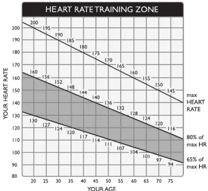
Studies show that to achieve the benefits of aerobic exercise, it is necessary to work within your training zone. Your training zone depends on your age and level of fitness.
The above chart indicates the recommended Heart Rate training zones (darkened area of the chart). These figuress are calculated by taking 220 minus your age, and calculating 80% for your maximum and 65% for the minimum heart rate for aerobic exercise.
CAUTION:
line
| YOUR AGE | YOUR HEART RATE | | --------- | --------------- | | 20 | 130 | | 25 | 127 | | 30 | 124 | | 35 | 120 | | 40 | 117 | | 45 | 114 | | 50 | 111 | | 55 | 107 | | 60 | 104 | | 65 | 101 | | 70 | 97 | | 75 | 94 |Heart Rate training zones are approximations. Always check with your physicians to learn what appropriate heart rate level is best for your fitness level.
HOW LONG SHOULD I EXERCISE?
The duration of your exercise session depends on your fitness level. In general, it is recommended that you maintain your heart rate in the training zone for at least 15 to 20 minutes to realize an aerobic benefit. Beginners should always start slowly and bring their workout sessions up to 20 minutes or more. As your fitness level improves, you will be able to maintain your heart rate in the training zone for longer periods of time. Usually between 20 and 30 minutes.
When first starting your workout, use the first several minutes to warm up, then slowly increase your workload to bring your heart rate into your specific training zone. At the end of your workout, gradually decease your workload, then exercise lightly as a "cool down".
HOW OFTEN SHOULD I EXERCISE?
Research indicates that to achieve the greatest benefits, exercise should be performed three to five times per week. It is important to allow sufficient time, at least 24 hours, for your body to recover after exercise.
9. MAINTENANCE
MAINTENANCE Error Messages
The following messages can appear on this product for diagnostic purposes.
ERR1 – Optic sensor error. The main program IC has not received the optic sensor signal. Re-start the unit to see if normal operation will resume.
ERR3 – Treadmill speed doesn't match the setting. Contact your local dealer for assistance.
ERR7 – Incline motor calibration error. Have a technician calibrate or replace the incline motor set.
SERVICE REQUIRED/TREADMILL SHUTTING DOWN /STOPPING – Excessive heat error. Turn off the treadmill. Then restart the treadmill as a test. Or, let the treadmill rest for one hour before restarting it. If the message persists, inspect the cable connection of the thermal sensor on the motor.
FOR ACCURATE HR, HOLD SENSORS FIRMLY WHILE WALKING – This message appears when someone touches contact heart rate pads and speed exceeds 4 mph or 6.4 kph. It is a reminder that the contact heart rate system functions best at low speeds when the user maintains a secure grip on the heart rate contact pads.
MAINTENANCE Fuse Replacement
When current is excessive, the fuse breaks to protect other components. Follow steps (a) through (g) to replace the fuse.
(a) Press the fuse holder cap.
(b) Turn it counterclockwise.
(c) The fuse and fuse holder cap will spring out.
(d) Remove the bad fuse from the fuse holder cap.
(e) Insert a fuse of the same type into the fuse holder cap.
(f) Insert the fuse holder cap and fuse into the channel.
(g) Turn the fuse holder cap clockwise to secure it in place.
Fuse specifications: 110V= 15 Amp, A(F); 220V= 10 Amp, A(F)
text_image
Technical diagram of a treadmill with labeled parts and exploded view, showing component assembly and adjustment steps.MAINTENANCE Lubrication
Periodic maintenance is crucial to the performance of fitness equipment, just like it is to the performance of an automobile. The better you maintain a product, the longer it will serve your needs. This treadmill requires periodic lubrication of the walk belt and has a built-in system to prevent overuse without maintenance.
Treadmill Lubrication Kit

text_image
SportsArt Proprietary Walk Belt/Deck Lubrication Kit Item:LUBE-04 SportsArt Proprietary HyperGlide™ Lubricant Item:LUBE-03 1 ounce (50cc) bottle = a one- time application for one unit Applicator tube Item:LUBE-02Periodic lubrication of this treadmill walk belt is so important that lubricant is provided with this treadmill. More lubrication kits can be found by contacting SportsArt Customer Service at (866) 709-1750. Always use SportsArt Hyper Glide™ lubricant.
MAINTENANCE Lubrication Prompt
When total distance on the treadmill exceeds 2500 miles (4000 km), the message "SERVICE NEEDED - APPLY LUBE" will appear after the walk belt stops rotating. This is a reminder to lubricate the treadmill. The treadmill can be operated normally until total distance exceeds 2560 miles (4100 km).
When total distance exceeds 2560 miles (4100 km), the message “SERVICE NEEDED - APPLY LUBE” will appear again after the walk belt stops rotating. At this point, this message will remain on the screen, and the treadmill will not operate, until the following process is completed.
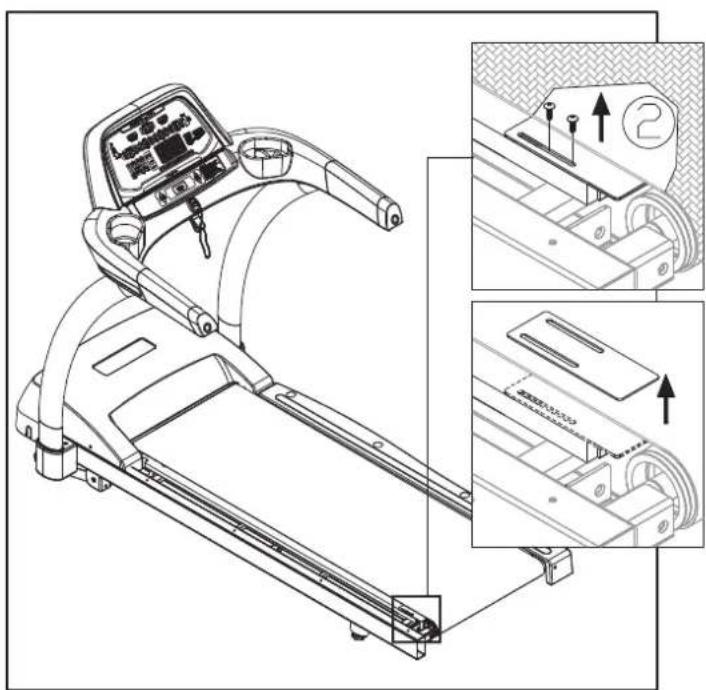
- Remove the left end cap and landing strip.

natural_image
Line drawing of a treadmill with control panel and labeled parts (no text or symbols beyond labels)- Remove screws from the finger guard on the left side. Then remove the finger guard.
natural_image
Line drawing of a treadmill with control panel and three inset views showing mechanical components (no text or symbols)-
Simultaneously press and hold INCLINE▲ + INCLINE▼ + 0 keys for two seconds. The treadmill will enter lubrication mode. It will operate at low speed and no▲ or▼ keys will operate.
-
Insert the applicator tube so the line on the applicator touches the side of the walk belt.
text_image
Technical diagram showing a mechanical assembly with labeled component 4 and directional arrow- Apply 50 cc from the bottle of liquid lubricant.

text_image
⑤-
Let the treadmill operate two to three minutes so the lubricant can disperse.
-
Remove the applicator and the bottle of lubricant.
text_image
Technical diagram showing a mechanical assembly with labeled components and directional arrow indicating motion or force.- Once the lubrication mode is activated, the message "PLEASE PRESS THE STOP KEY AFTER FINISHING LUBRICATION" will appear on the screen. At this point, press the STOP key to deactivate the lubrication mode. This clears the lubrication distance value. A new lubrication distance value will begin to accrue.
After the lubrication process has been completed, secure the finger guard back into place. Make sure that the finger guard is placed in the correct direction, as shown, and make sure that the space between the finger guard and the rear roller is 1/8 to 7/32 inch (2 to 6 mm). If necessary, make cuts in area A to allow proper placement of the finger guard.

text_image
Technical diagram of a treadmill with labeled parts and exploded views showing mechanical assembly steps- Secure the end cap and landing strip onto the treadmill.
natural_image
Line drawing of a treadmill with control panel and numbered component (no text or symbols)Note: The lubrication mode can be activated at any time. If you notice a buildup of static electricity or that the bottom side of the walk belt is dry, applying lubricant may help. Activate the treadmill's lubrication mode at any time. Walk belt lubrication, along with other maintenance, can extend the life of your treadmill.
MAINTENANCE Check List
Like cars, fitness products require maintenance. Regular maintenance extends the life of your fitness product, and failure to provide regular maintenance will void your warranty. Copy the maintenance log sheet and record maintenance work.
Daily tasks
- Check the product, including the safety key, for safe operation. Secure any loose screws. If you have questions about the operation or safety of a product, unplug it and place an Out-of-Service note on the product until the issue is resolved.
- Use a clean, lint-free towel, dampened with a mixture of Simple Green and water, to wipe the product clean. Include the display, grips, handrails, walk belt, and landing strips. (Do NOT use cleaners with alcohol, ammonia or other damaging chemicals. Never spray or pour any liquid directly on the product.)
Monthly tasks
- Inspect the power cord for damage. Replace if necessary.
- Make sure handles, pedestals, and other parts are secure, and that screws are tight.
- Check walk belt tension and alignment. Adjust if necessary. Do not over tighten.
Quarterly tasks
-
Use a lint-free towel and diluted Simple Green to clean the walk deck. Lubricate the walk deck with SportsArt Hyperglide™ lubricant, part lube-03, and cancel the lubrication prompt (see manual). Note that at 2500 miles (4000 KM), SportsArt treadmills prompt users to lubricate the walk deck.
-
Inspect the walk belt and deck for wear. Note: When replacing the walk belt, flip or replace the walk deck: Always provide a fresh contact surface for a new walk belt.
-
For DC motor treadmills, remove motor brushes. Remove loose carbon out of the motor brush area. (Do not breathe or let others breathe motor brush carbon. Collect it in a damp cloth or vacuum.) Replace brushes when they are under 12 -inch long. Note: if used often, your treadmill may require brush maintenance more often.
Half-yearly tasks
- Turn off unit power. To allow capacitors to discharge, wait five minutes before disconnecting power cord. Remove the motor cover. Vacuum the area around the drive motor and board. Avoid bumping wires or components.
- Check drive belt for wear. Replace it if there are cracks or damage. (Note: SportsArt drive belts last a long, long time. Chances are you will not have to replace a drive belt within the warranty period.) Align pulleys if needed.
-
Use a clean, lint-free cloth, dampened with a mixture of Simple Green and water, to clean the rollers and other moving parts.
-
Clean and lubricate walk deck bushings. For lubrication of deck bushings, use red lithium grease. Remove bushing lubricant that touches the walk belt or deck surface.
General Notes on Maintenance
Note that product maintenance requirements depend on usage and environment. This schedule is based on average use. Some products may require maintenance more often than is suggested here. Please call the SportsArt Service department at 1-866-709-1750 if you have questions.
To check walk belt tension:
a. First, center the belt. (See d. below.) Operate the treadmill at 1.2-2.5 mph or 2-4 kpm.
b. Hold onto the handles. Press your feet against the walk belt. If the front roller keeps moving but the walk belt stops rotating, the walk belt tension should be increased.
c. To adjust the walk belt, turn roller screws clockwise 12 turn at a time. Then retest walk belt tension. To avoid premature wear on components, do not over tighten the walk belt.
d. Note: Turning rear roller screws clockwise extends the rear roller toward the back of the unit, increasing walk belt tension. Turning rear roller screws counterclockwise brings the rear roller closer toward the front of the unit, decreasing walk belt tension. By adjusting one screw clockwise, that side of the roller extends toward the back of the treadmill, forcing the walk belt toward the other side. Always check walk belt centering after each adjustment. Avoid making the walk belt hit one side or another.
Caution:
Use standard safety procedures when accessing electrical parts. For products with power cords, turn off unit power. Allow capacitors to discharge by waiting five minutes before disconnecting the power cord from the power socket. After waiting five minutes, remove covers to access the drive board and other components. For products without power cords, let the unit sit without use for five minutes before accessing drive boards and other components.
MAINTENACE One-Year Maintenance Log
Facility Name:
Maintenance Supervisor:
Product serial number:
Product Model Number:
Start Date:
End Date:
| Daily Tasks | Week1 Week2 | Week3 Week4 | ||||||||||||||||||||||||
| 1.Safe | ||||||||||||||||||||||||||
| 2.Clean | ||||||||||||||||||||||||||
| Daily Tasks | Week5 Week6 | Week7 Week8 | |||||||||||||||||||||||||
| 1.Safe | |||||||||||||||||||||||||||
| 2.Clean | |||||||||||||||||||||||||||
| Daily Tasks | Week9 Week10 Week11 Week12 | |||||||||||||||||||||||||||
| 1.Safe | ||||||||||||||||||||||||||||
| 2.Clean | ||||||||||||||||||||||||||||
| Monthly Tasks | Months 1-3 Months | Months 4-6 Month 7-9 Month 10-12 | |||||||||
| 1.Power cord | |||||||||||
| 2.Pedestal | |||||||||||
| 3.Check walk belt | |||||||||||
| Quarterly Tasks | Quarter 1 | Quarter 2 | Quarter 3 | Quarter 4 | ||||||||
| 1. Clean deck | ||||||||||||
| 2. Inspect belt | ||||||||||||
| 3. DC motor | ||||||||||||
| 1/2--Yearly | First half of the year | Second half of the year |
| 1.Vacuum | ||
| 2.Drive belt | ||
| 3.Rollers | ||
| 4.Deck bushings |
10. BLOCK DIAGRAM
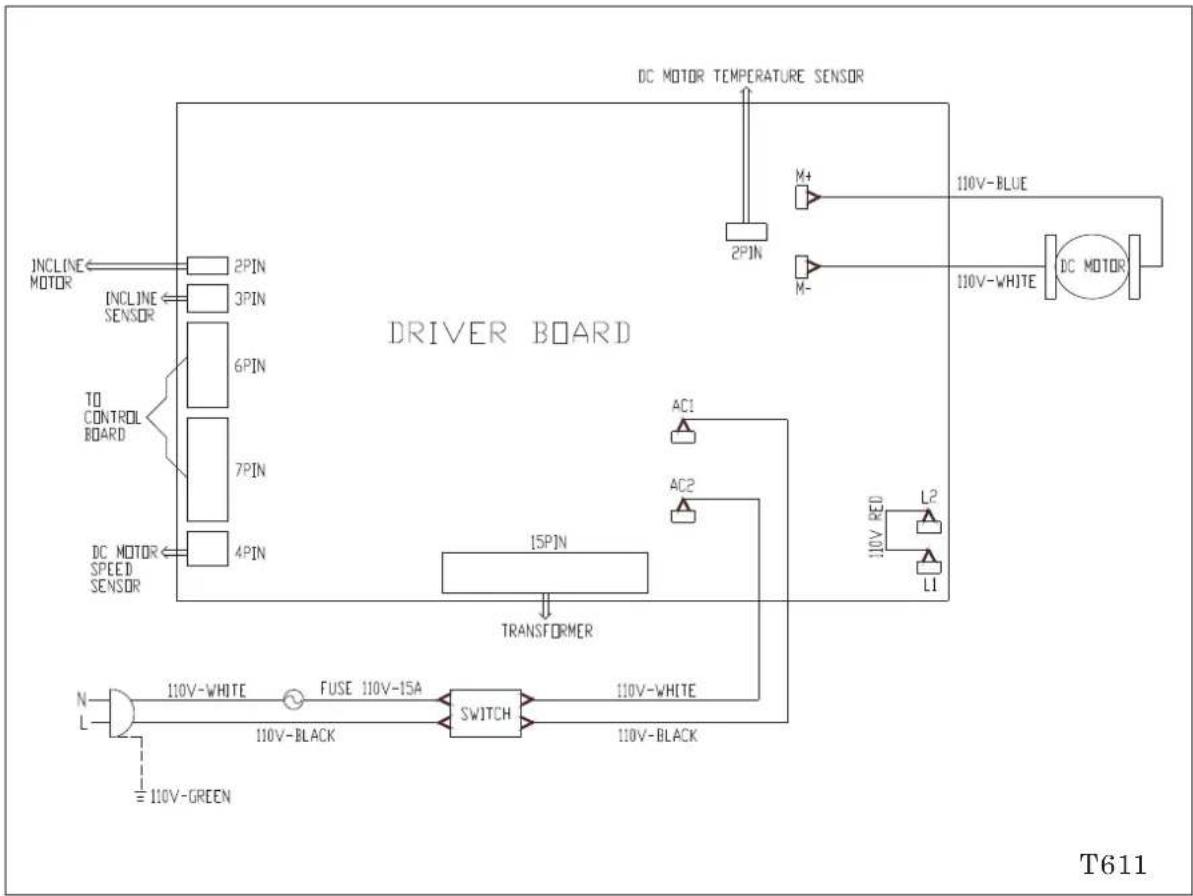
flowchart
graph TD
    A["INCLINE MOTOR"] --> B["2PIN"]
    C["INCLINE SENSOR"] --> D["3PIN"]
    E["TO CONTROL BOARD"] --> F["6PIN"]
    G["DC MOTOR SPEED SENSOR"] --> H["4PIN"]
    I["DC MOTOR TEMPERATURE SENSOR"] --> J["2PIN"]
    K["AC1"] --> L["15PIN"]
    M["AC2"] --> N["15PIN"]
    O["110V-RED"] --> P["L2"]
    Q["L1"] --> R["L2"]
    S["N L"] --> T["110V-WHITE"]
    T --> U["FUSE 110V-15A"]
    U --> V["SWITCH"]
    V --> W["110V-BLACK"]
    X["T611"] --> Y["110V-BLACK"]
    Z["110V-BLACK"] --> AA["AC1"]
    AB["110V-BLACK"] --> AC["AC2"]
Your Authorized Distributor