3108 - Treadmills SportsArt - Free user manual and instructions
Find the device manual for free 3108 SportsArt in PDF.

User questions about 3108 SportsArt
0 question about this device. Answer the ones you know or ask your own.
Ask a new question about this device
Download the instructions for your Treadmills in PDF format for free! Find your manual 3108 - SportsArt and take your electronic device back in hand. On this page are published all the documents necessary for the use of your device. 3108 by SportsArt.
USER MANUAL 3108 SportsArt
text_image
OWNER'S MANUAL ASSEMBLY INSTRUCTIO SPORTS/ARTOWNER'S MANUAL
ASSEMBLY INSTRUCTIONS
TABLEOF CONTENTS
-
SAFETY GUIDELINES.... 1
-
ASSEMBLING YOURTREADMILL InstallationRequirements.... 2
Listofparts.... 4
Stepbystepinstructions.... 5
Stepbystepinstructions(Iftheunitwithhandrails).... 7
Floor level adjustment.... 11 -
OPERATINGINSTRUCTIONS Safety key.... 12
-
UNDERSTANDING THE ELECTRONICS PACKAGE MANUALmode.... 13 INTERVAL course.... 13 PROGRAM mode.... 15 HRC 65% / HRC 80%.... 16
-
KEY FUNCTIONS Whateachofthecategoriesmeans.... 17
-
RUNNING ON THE TREADMILL.... 18
-
GUIDELINESFOREXERCISE How long should I exercise?.... 19 Howoftenshouldlexercise?.... 19
-
MAINTAININGYOURTREADMILL Cleaningthetreadmill.... 20 Adjustingtherunningbelt.... 21
-
TROUBLE SHOOTING ERRmessages.... 25 ERR messages for contact heart rate.... 25 Blank display.... 26 Electronicspackageandmotor fusefailure.... 27
-
Wiring schematic.... 28
SAFETY GUIDELINES:
Please read and follow the following safety guidelines:
Before beginning any exercise program, you should consult with your doctor. It is recommended that you undergo a complete physical examination.
- Read this owner's manual carefully and follow the instructions.
- Assemble and operate the treadmill on a solid, level surface. Keep the area behindthetreadmillclear.
- Never allow children on or near the treadmill. The running belt will not stop immediately if any object becomes caught in the belt or rollers.
- Check the treadmill before every use. Make sure all parts are assembled, and all nuts and bolts are tightened. Do not use the treadmill if the unit is disassembled inanyway.
- Keephandsawayfrommoving p arts.
- The weight limit for this treadmill is 300 lb. (135 kg).
- Wear proper workout clothing: Do not wear loose clothing. Do not wear shoes with leather soles or high heels. Tie back all long hair.
- Don't rock the unit from side to side. Care should be taken when mounting and dismounting t heunit.
- Straddle the machine with your feet on the right and left staging platform before starting t herunningbelt.
- Donotplaceanyliquidsonanypartofthetreadmill.
- To prevent shock, keep all electric components such as the motor, cord, and switchaway from water.
- Turn off the treadmill while adjusting or working near the roller.
- Do not use any accessories that aren't specifically recommended by the manufacturer, these might cause injuries or cause the unit to fail.
- Work within your recommended exercise level, do NOT work to exhaustion.
- If you feel any pain or abnormal sensation, STOP YOUR WORKOUT and consult yourphysicianimmediately.
The treadmill is designed for your use and enjoyment. By following the above precautions and using good judgment and commonsense, you will enjoy safe and pleasurable exercise with this treadmill.
ASSEMBLING YOUR TREADMILL:
Installationrequirements
Read this owner's manual and follow the instructions contained herein.
CAUTION: To avoid back strain, and to ensure safety to the unit and yourself, we suggest you may need a helper to remove the running deck assembly from box.
text_image
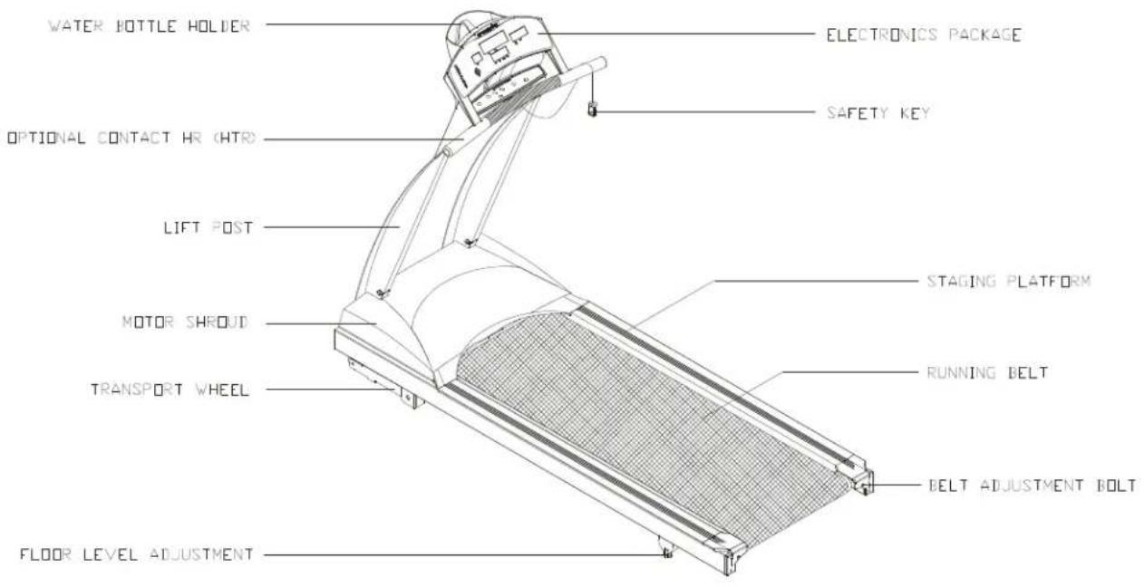
WATER BOTTLE HOLDER ELECTRONICS PACKAGE OPTIONAL CONTACT HR (HTR) SAFETY KEY LIFT POST STAGING PLATFORM MOTOR SHROUD RUNNING BELT TRANSPORT WHEEL BELT ADJUSTMENT BOLT FLOOR LEVEL ADJUSTMENTIftheunitwithhandrails

text_image
WATER BOTTLE HOLDER ELECTRONICS PACKAGE OPTIONAL CONTACT HR (HTR) LANDRAILS SAFETY KEY LIFT POST STAGING PLATFORM MOTOR SHROUD RUNNING BELT TRANSPORT WHEEL BELT ADJUSTMENT BOLT FLOOR LEVEL ADJUSTMENTListofparts
Beforeassemblingyourtreadmill, makesurethatyouhaveallthefollowingitems:
- Onesafetykey
- OnehexAllenwrench(M6) with T-handle
- OnehexAllenwrench(M5) with T-handle
- OnehexAllenwrench(M5)
- OnehexAllenwrench(M4) with T-handle
- Onefuse15ampfor100-120voltuse; 10ampfor200-240voltuse
- FourM4xL12Philipsscrews - electronicspackage
- One2-wayScrewdriver
Ifanyitemsaremissing, contactyourauthorizedservicedealer.
IMPORTANT: Thepackingforthistreadmillisdesignedtoprotectitduringshipment. Pleasestoretheoriginalpackagingin a safeplaceincaseyouneedto shipthetreadmillinthefuture.
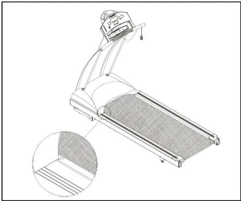
Stepbystepinstructions
The following stepsexplain how to assemble your treadmill. Pleasereade every step thoroughly and follow the directions completely to ensure correct assembly.
-
There are important parts enclosed inside of the Styrofoam, please check the Styrofoam compartments before discarding. Makesure all packing materials are removed from the treadmill deck.
-
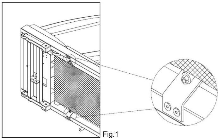
Lay the treadmill on its side. Make sure the running belt is position in the tracks of the two BELT ALIGNMENTROLLERundersideofthemachine(see Fig. 1).
Fig.1
-
Then, place the treadmill on a level, flat surface.
-
Bring the side post to their upright positions. Attach the screws to the lift post. Do nottightenyet. (seeFig. 2)
Fig.2
- Secure the front posts with the four screws provided. Do not tighten yet. (see Fig. 3)
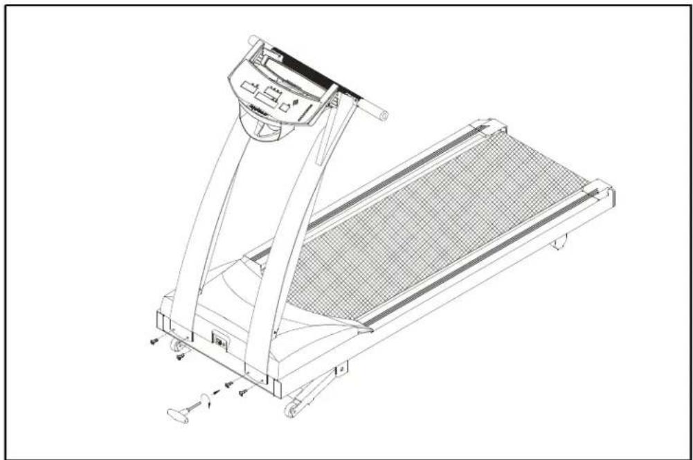
natural_image
Technical line drawing of a treadmill with wheels and control panel (no text or symbols)Fig.3
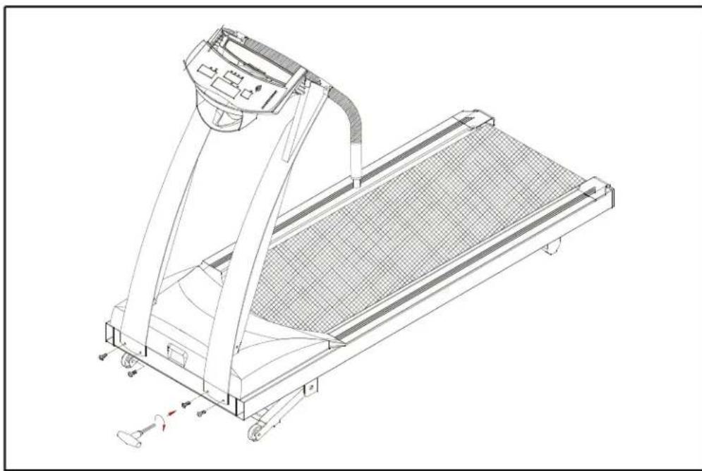
- Use the screwdriver to tighten all screws securely. (see Fig. 4)

text_image
Technical diagram of a treadmill with three circular insets showing component views and directional arrows.Fig.4
Stepbystepinstructions(Iftheunitwithhandrails)
The following stepsexplain how to assemble your treadmill. Pleasereade every step thoroughly and follow the directions completely to ensure correct assembly.
-
ThereareimportantpartsenclosedinsideoftheStyrofoam, pleasecheckthe Styrofoamcompartmentsbeforediscarding. Makesureallpackingmaterialsare removedfromthetreadmilldeck.
-
Lay the treadmill on its side. Make sure the running belt is position in the tracks of the two BELT ALIGNMENTROLLERundersideofthemachine(see Fig. 1).
natural_image
Technical line drawing of a mechanical component with a magnified inset showing detail (no text or symbols)-
Then, place the treadmill on a level, flat surface.
-
Bringthesideposttotheiruprightpositions(includingthehandlebarandthe electronics package). Attach the screws to the lift post. Do not tighten yet. (see Fig. 2)

natural_image
Technical line drawing of a treadmill with control panel and side-mounted legs (no text or symbols)Fig.2
- Using two 5/16" screws provided on each post. Do not tighten yet. (see Fig. 3)
natural_image
Technical line drawing of a treadmill with wheels and control panel (no text or symbols)Fig.3
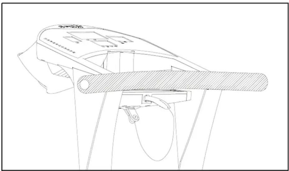
- Loosen the screws of fixing the handlebar and remove the steel plate. (see Fig. 4)

natural_image
Technical line drawing of a treadmill with an inset close-up showing the mechanism (no text or symbols present)Fig.4
- Turn up the handlebar and fasten the screws. Do not tighten yet. Make sure to assemble the handlebartotheliftpostcorrectly. R toRwhicharemarkedonthe handlebarandliftpostrespectively. (seeFig. 5)
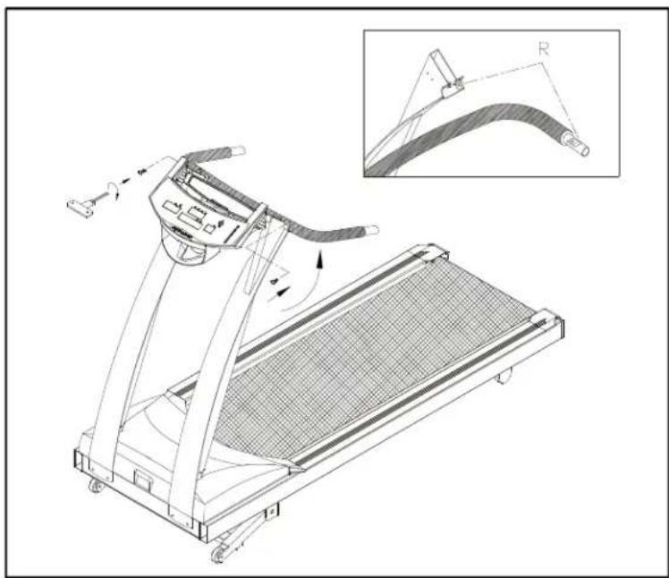
natural_image
Technical line drawing of a treadmill with an inset showing a curved mechanical component (no text or symbols present)Fig.5
If the Hand Touch Readout (HTR) is applicable, before fastening the screws, connectthewiresfromthedisplayandtheHand TouchReadouthandlebar securely, as shown in Fig 6. Then fasten the screws of the handlebar. Do not tightenyet.
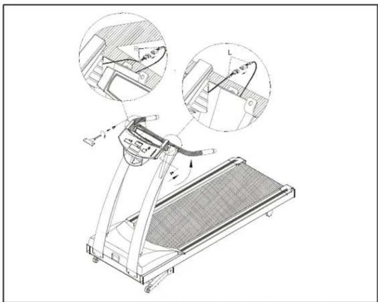
natural_image
Technical line drawing of a treadmill with two circular insets showing mechanical components (no text or symbols)Fig.6
Caution: Please make sure to connect the wires correctly, R to R and L to L which are marked on the wirest themselves.
Note: Theabovetwoscrewstothehandlebararespeciallyprovidedby manufacturer. Do not attempt to substitute any other screw.
- Use the screwdriver to tighten all screws securely. (see Fig. 7)
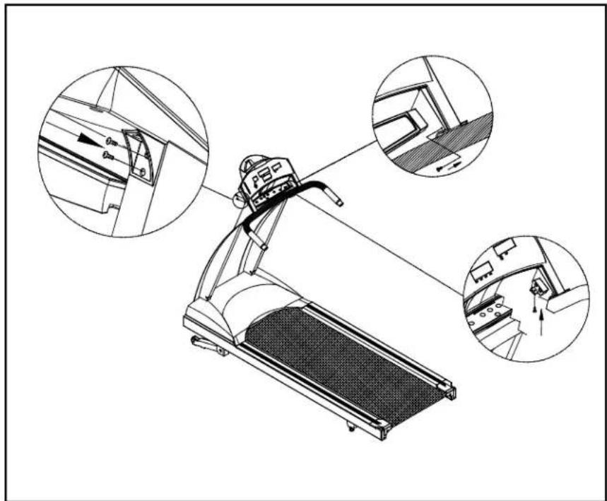
natural_image
Technical line drawing of a treadmill with three circular insets showing internal components (no text or symbols)Fig.7
- Insertthetwohandrailsintothehandlebarsandthenfastenthescrewsprovided. Lastlysecurethehandrailclampbyfasteningthescrews. (seeFig. 8)
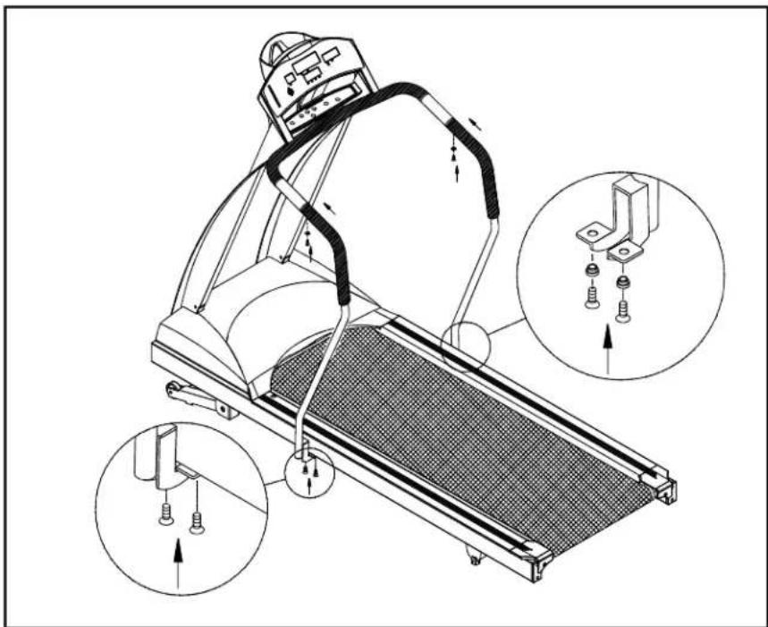
natural_image
Technical line drawing of a treadmill with mechanical components and three inset views showing assembly details (no text or symbols)Fig.8
Pleasenote: Thescrewstothehandrailclamp(Fig.8) arespeciallyprovidedby manufacturer. Do not attempt to substitute any other screws. Any questions, pleasecontactyourdealer.
- Secure the screws in front of the lift posts and handlebar tightly, Secure the screwstotheliftpostightly. (seeFig. 9)

text_image
Technical diagram of a treadmill with labeled parts and zoomed-in detail viewsFig.9
Floorleveladjustment
If the treadmill is not steady on your floor, turn the floor level adjustment on the rear feetlegofthetreadmill. Raiseorlowerthefloorleveladjustmenttosteadyyour treadmill(seeFig. 10).
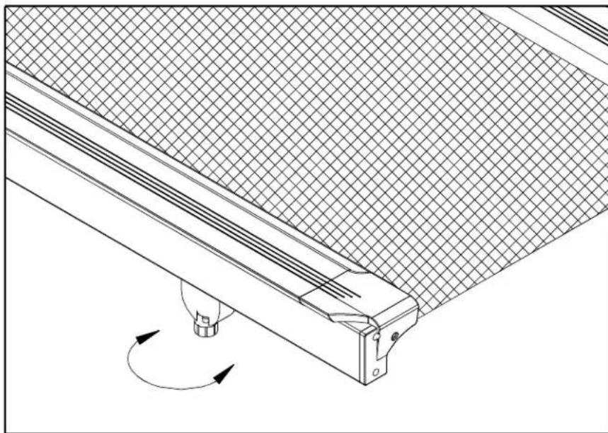
natural_image
Technical line drawing of a mechanical assembly with a grid-patterned panel and rotating component (no text or symbols)Fig.10
Yourtreadmillisassembledandreadytouse.
OPERATINGINSTRUCTIONS
CAUTION: DONOTSTANDONTHEBELTWHENSTARTING.
Safetykey
The safety key is required to operate the treadmill. The safety key should be used for an emergency stop switch by clipping the cord to your exercise clothing. After you have finished your workout, be sure to store the safety key in a safe place to avoid use of the treadmill by children or persons unfamiliar with this treadmill.
Turn on the power switch located on the front of the treadmill. Insert the safety key into the SAFETY KEY socket of the electronics package in order for the unit to operate.
UNDERSTANDING THE ELECTRONICS PACKAGE
A. Turn on the power switch located on the front of the treadmill, then the electronics will scroll through with the message "PLACE SAFETY KEY". The treadmill will not function without placing the safety key in its position (see Fig 11).
natural_image
Technical line drawing of a mechanical device with no visible text or symbolsFig.11
B. After you put the safety key in place, the unit will scroll "SELECT MODE USER1-USER4". Or you can press the SPEED ▼▲ keys to start the motor. To input your personal information, please follow the steps below.
C. Use the ▼▲ keys to select User 1 through User 4. Once you have made your choice, press "ENTER" to confirm your input. The electronics will then scroll the message SELECT MODE ▼▲ MPH/KPH". You can press the ▼▲ keys to choose mph or kph, then press "ENTER" to confirm your input. You will be prompted to input your weight. If you choose mph, the unit of weight used is LB. Use the ▼▲ keys to set up your weight. Pressing the key once changes the weight 1LB/1KG. Holding the key will change the weight by 10LB/5KG. After you have selected your desired weight, press "ENTER" to confirm your input. The electronics package automatically recalls the program that was used last.
D. Press the "Scroll" key to choose your desired program, such as Manual, Program, Interval, HRC.
MANUAL
A. Press the "Scroll" key until the Manual LED lights up. When "MAN'L" appears in the display window, you will be in the MANUAL course.
B. PresstheSPEEDkeysstartthetreadmill. Thetreadmill'sspeedrangeis 0.1-11MPH(0.2-18KPH). PleasepresstheSPEEDkeystonreaseorto decreasethespeed.
C. Press the INCLINE ▼▲ keys to raise or lower the treadmill. The incline range is 0-15%.
D. Press the MODE key, and this will scroll you through the different modes on the smaller display window. With each press of the MODE key, the display will alternately show TIME, DIST(distance), CAL(calories), HR and SCAN.
INTERVALcourse
A. CustomInterval:
- Press the "Scroll" key until Custom Interval LED flashes and the larger display window will show "INTV 1". If this is the interval program you want, then press "ENTER". The message "ENTER REST SPEED & INCLINE &TIME" will scroll through the window. REST will show up in the center display.
- You can input SPEED, TIME and INCLINE for the REST Mode of Interval 1.
a. UsetheSPEEDkeys▲selectyourdesiredREST speed.
b. Use the ▼▲ keys to adjust your desired REST time. Time can be set from 60-255 seconds.
c. You can use the incline ▼▲ keys to select your desired REST incline.
d. Once you have set your desired REST levels, press ENTER to record them. If you don't press ENTER to confirm your choices, you will be prompted to press ENTER.
- After the REST levels have been set, the display will scroll through "ENTER WORK SPEED & INCLINE & TIME. WORK will appear in the center display.
- You can now input SPEED, TIME and INCLINE for the WORK Mode of Interval 1. Please follow the abovestepstoinputyourchoices. Once you have set your desired WORK levels, press ENTERtorecordthem.
-
After you have set your desired REST and WORK levels, you will be prompted to ENTER TOTAL TIME. Use the ▼▲ keys to set your desired total time (from 00:00-99:00). Then press ENTER to confirm and to start the treadmill. When the totaltimecountdownreaches00:00, the electronics displaywillbeepfor10 seconds.
-
When the REST segment is over, the display will show "GOING TO WORK" and thenthemachinewillusethesettingsyouchosefortheWORKsegment(speed andincline). Ifyouneedtochangeanyofthesettingsduringyourworkout, please refer to step 2 above. When the WORK TIME is over, the display will show "GOING TO REST", and return to the settings that you chose for the rest levels.
- PresstheMODEkeytoscrollthroughthedifferentmodesonthesmallerdisplay window. Each press of the MODE key will alternately show TIME, DIST, CAL, HR orSCAN.
-
Keepinmindtherangesofthetreadmillareasbelow: SPEEDrange:0.1-11MPHor0.2-18KPH INCLINERange:0-15% REST/WORKTIMErange: 60-255seconds
B. CustomProgram -
Press "Scroll" key until the Custom Interval LED flashes and the larger display windowwillshow"INTV2".
-
Interval2allowsyoutodesignyouownpersonalizedworkoutprogram. Thereare eightprogrammablesegmentsinInterval2. Ifthiscourseistheoneyouwant, pressENTER, andyouwillbepromptedtoENTERSEGMENT1SPEED & INCLINE & TIME. Please input the speed/incline/time for SEGMENT 1.
S1willappearinthelarger LEDwindow. UsetheSPEED ▼▲keystosetyourdesiredspeed. Use ▼▲ keys to set your desired time. Time range is 0-99 minutes. UsetheINCLINE ▼▲keystosetyourdesiredinclineheight.
- For segment 2-8, please refer to the instruction as in Segment 1 above. Once all segments are set, press ENTER to confirm the settings for INTERVAL 2.
- PresstheMODEkeytoscrollthroughedifferentmodes. Witheachpressofthe MODE key, the display will alternately show TIME, DIST, CAL, HR or SCAN.
PROGRAMmode
A. Press the "Scroll" key until the pre-program LED flashes and the larger display windowwillshow"PRO:1\~PRO:6".
B. Therearesix(6) programsavailable.
Thecourseprofileforeachprogramisasfollows:
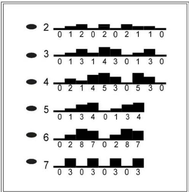
bar
| Category | Value | |---|---| | 2 | 0 | | 2 | 1 | | 2 | 2 | | 2 | 0 | | 2 | 2 | | 2 | 0 | | 2 | 2 | | 2 | 0 | | 3 | 0 | | 3 | 1 | | 3 | 3 | | 3 | 1 | | 3 | 4 | | 3 | 3 | | 3 | 0 | | 3 | 1 | | 3 | 3 | | 3 | 0 | | 4 | 0 | | 4 | 2 | | 4 | 1 | | 4 | 4 | | 4 | 5 | | 4 | 3 | | 4 | 0 | | 4 | 5 | | 4 | 3 | | 4 | 0 | | 5 | 0 | | 5 | 1 | | 5 | 3 | | 5 | 4 | | 5 | 0 | | 5 | 1 | | 5 | 3 | | 5 | 4 | | 6 | 0 | | 6 | 2 | | 6 | 8 | | 6 | 7 | | 6 | 0 | | 6 | 2 | | 6 | 8 | | 6 | 7 | | 6 | 0 | | 7 | 0 | | 7 | 3 | | 7 | 0 | | 7 | 3 | | 7 | 0 | | 7 | 3 | | 7 | 0 | | 7 | 3 |C. When you have chosen the program that you want, press the ENTER key. You will then be prompted to select DIST or TIME. Usethe keysto watch between DIST and TIME, then press ENTER to confirm your decision.
D. Use the ▼▲ keys to set your desired distance or time, then press ENTER.
E. The program will be displayed in the large LED window. The treadmill will start once you press the SPEED up key. You can control the speed during these programs, and the unit will automatically switch between elevation percentages, giving you the feeling of running on hills or climbing on them.
F. Use the MODE key to switch between TIME, DIST, CAL, HR or SCAN on the LED window.
G. When you reach your desired TIME or DIST, the unit will beep for 10 seconds. After that the machine will continue to count up if you continue your workout.
HRC-65% / HRC-80% (if your electronics package includes the HRC feature)
A. Press the "Scroll" key until the HRC 65% or 80% LED flashes and the larger displaywindowwillshow"FATorCARDIO".
B. When you press the ENTER key, INPUT YOUR AGE will scroll through the display, then it will show AGE 35. Please use ▼▲ keys to choose your age, and the relative target heart rate number will be changed accordingly. Input your age, then press ENTER. The message "MODIFY YOUR HEART RATE LIMIT" will scroll through the display, and MDFY will appear in the window. Use the ▼▲ keystomodifyyourtargetheartratenumber, andpressENTERtoconfirmyour choice. Then TIME will appear in the window, then press the MODE ▼▲ keys to setyourdesiredtimeforthehearratecontrol. ThenpressENTERtoconfirmyour input.
Thelargerdisplaywillshowyourcurrentheartrateandyourtargetheartrate figure. Press the SPEED ▼▲ keys to set the max. speed and start the motor. If themachinedoesnotreceive a heartratesignal, youwillbeunabletostartthe treadmill.
C. For more detailed information about the HRC function, please refer to the Heart RateControlOperationmanual.
KEYFUNCTIONS:
SCROLL: Will scroll through each function--Manual, Program, Interval and HRC.
SPEED: UsetheSPEEDkeys▲speeduporslowdownthetreadmill. The speedrangeis0.1-11MPHor0.2-18KPH.
INCLINE: UsetheINCLINEkeysbraiseorlowerthetreadmill. Theincline rangeis0-15%.
MODE: Whenyouinsertthesafetykeyinplace, theelectronicspackagewill automaticallyaccesstheMODEfunction. PresstheMODEkeytoscroll through the different modes. With each press, the display will alternately show TIME, DIST(distance), CAL(Calories), HR(heart rate), or SCAN.
▼▲ KEYS: These keys are used to choose desired TIME, DISTANCE, USER 1 - 4, MPH/KPH/WEIGHT.
SAFETY KEY: Turn on the power switch located on the front of the machine. Insert it intopositiontooperatethetreadmill.
STOP: When you press the STOP key, the treadmill will come to a gradual stop and be paused. Pressthiskeyonceagaintocontinueyourworkout. Alldatawill be saved. If you want to clear all your date, hold the stop key and the unit will bereset.
ENTER: Pressthiskeytoconfirmallinputinformation.
Whateachofthecategoriesmeans:
TIME: TherangeavailableinTIMEmodeis00:00-99:59minutes. UsetheMODEkey to select the time mode. When the TIME LED is lit in the display, use the ▼▲ keystoadjustyourdesiredtime. Eachpressof thekeychangesthetime by1minute.
Theelectronicspackagewillbeepfor 3 secondswhenyourdesiredtimeis reached, thenitwillstarttocountupifyourworkoutcontinues.
DIST: The distance range of your treadmill is 0-99.99 miles or 0-999.9 kilometer. Use the MODE key to select the DIST mode. When the DIST LED is lit in the display, use the ▼▲ keys to adjust the desired distance. Each press of the keychangesthedistanceby0.05mileor0.1km.
Theelectronicspackagewillbeepfor3secondswhenyourdesireddistance isreached, thenitwillstarttocountupifyour workoutcontinues.
CAL: This readout gives you the amount of calories burned, therange of calories is from 0-999.9.
SCAN: TheSCANwillalternatethedisplaybetweenalltheModereadoutsevery4 seconds.
HR: Thisreadoutgivesyoutheheartrateofyourworkout.
RUNNING ONTHETREADMILL:
Now, you have become familiar with your treadmill's operation and are ready to exercise:
- Turn the power switch ON, and place the safety key on the "SAFETY KEY" position.
- Straddlethebeltwithyourfeetontherightandleftstagingplatforms. Clipthe safetykeytoyouexerciseclothingatyourwaistline.
- Straddle the belt, balancing one hand on the handrail. Press SPEED key to start the treadmill. Adjust the speed ▲ key until you reach 1.5-2.0 MPH / 2.5-3.5 KPH, a comfortable walking speed. With both hands on the handrails, place one foot, thentheotheronthetreadmill, andwalkforafew minutestogetcomfortablewith yourmachine.
- After you are walking in an easy, relaxed, and steady fashion, release your grip on the handrails, and let your arm swing freely and naturally.
- When you feel comfortable walking, you may wish to jog. Hold the handrail with onehand, using your other hand to increase the speed.
- Remember to hold the handrail when using the control panel on the electronics package. Holding the handrail with one hand will help to maintain your balance, especially when slowing down or stopping. Also, remember to hold onto the handrail whendismounting.
- When you have finished your workout, movethesafety key from the "SAFETY KEY" position. Always remember to cool down after your workout before completely stopping.
GUIDELINESFOREXERCISE
Howlongshould I exercise?
Thedurationofyourexcisesessionisdependentonyourfitnesslevel. Ingeneral, itisrecommendedthatyoumaintainyourheartrateinthetrainingzoneforatleast 10 minutes to realize an aerobic benefit. As your fitness level increases, you will be abletomaintainyourheartrateinthetrainingzoneforlongerperiods, usually between20and30minutes.
Whenfirststartingyourworkout, usethefirstseveralminutestowarmup, then slowlyincreaseyourworkloadtobringyourheartrateintoyourspecifictraining zone. At the end of your workout, gradually decrease your workload, then exercise lightlyasa"cooldown".
Howoftenshouldlexercise?
Aerobic exercises, to achieve the greatest benefits, should be performed 3-5 times a week. It is important to allow sufficient time, at least 24 hours, for your body to recoverafterexercise.
MAINTAININGYOURTREADMILL
Your treadmill relies on low friction for peak performance. The treadmill's low friction operation is dependent on keeping the unit as clean as possible. See "Cleaning the Treadmill" form more information.
Properbeltalignmentisalsoimportantforproperoperationofthetreadmill. See "AdjustingtheRunningBelt" formoreinformation.
Cleaningthetreadmill
CAUTION: TurnoffunitanddisconnectACcordbeforecleaning.
Regularcleaningisrecommendedtokeepyourtreadmillrunningatpeak Performance.
Before your workout, use a dry cloth to clean the staging platform, exposed slider deck, and underthebeltasfarasyoueasilyreach. This removesanydirtordust which might enter the slider area and compromise the unit's running efficiency.
To clean the plastic parts, use a mild detergent and make sure the unit is completely dry before operating. On the running surface, use a soft nylon scrub brush.
Donotusewatertocleanthebeltorrunningsurface, ortocleantheelectronics package. Should water, for some reason, get on the electronics package, immediatelyblowdrytheelectronicspackage.
It is recommended that you keep all liquids away from the unit during operation. Spillage of liquids onto or into them, machine will void the warranty.
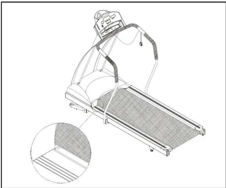
Adjustingtherunningbelt
Your treadmill comes with a belt alignment gauge located on the deck. (see Fig.12) Theedgeoftherunningbeltshouldbeinthemiddleofthegreenportionofthe gauge. If the belt edge is in the green area, the belt does not need adjusting. If the beltedgeisintheredportion, thebeltneedsadjustingimmediately.
natural_image
Technical line drawing of a treadmill with mesh cover and inset detail (no text or symbols)Fig.12
Iftheunitwithhandrails
natural_image
Line drawing of a treadmill with mesh pattern and inset detail (no text or symbols)The belt is properly aligned at the factory. However, during shipping and handling or by use on an uneven surface, the belt may move off center. Therefore, it is important that you check the belt's alignment before using the treadmill.
The correct alignment of the running belt is critical for the smooth operation of the treadmill.
CAUTION: DO NOT ALLOW ANYONE TO WALK ON RUNNING BELT DURING THIS PROCEDURE.
Failure to realign the belt could result in tearing or fraying of the belt, which is not coveredinthewarranty. Pleasefollowtheadjustmentprocedurelistedbelow:
- Turn on the power switch located on the front of machine. Insert the SAFETY KEY ontheitsposition.
- Press the SPEED ▲ key to increase the speed until the speed registers 2.0mph / 3.2kphonthedigitaldisplay.
- While the unit is running at 2.0mph/3.2kph, determine where the belt is in relation to the belt alignment gauge.
- Should your belt be in the wrong color range, follow the steps below to return the belttothe"safetyzone":
- If the belt is in the left red zone: Turn the left belt adjustment bolt located at the rear of the treadmill clockwise 1/4 turn at a time, using the hex Allen wrench. Thenturntherightbeltadjustmentboltcounterclockwise1/4turn. Letthe treadmill run 30 seconds, then check the position of the belt in the color gauge. If thebeltstillhasnotreturnedtothegreensafetyzone, repeatwithanother 1/4 turnuntilthebelthasreturnedtothemiddleofthegreenarea. Donotturn adjustingboltmorethan1/4turnatonetime.
If the belt is on the edge of the greencolor, please adjust its to it in them middle of the green color. You may turn the adjustment nut less than 1/4 turn at one time. - Conversely, if the belt is in the right red zone, turn the right belt adjustment nut clockwise1/4turn, thenturntheleftadjustmentboltcounterclockwise1/4turn. Thenletthetreadmillrunatleast30seconds, checkthepositionofthebeltinthe color gauge. If it still has not returned to the green safety zone, repeat with another 1/4turnuntilthebelthasreturntothemiddleofthegreenarea. Donot turnadjustingboltmorethan1/4turnatonetime.
- When the belt is back in the green "safety zone", you can continue your regular useofthetreadmill. Slowlyincreasethespeedoftheunitto5.5MPH(9KPH), andletitrunfor atleast45seconds.
Periodically monitor the position of the belt to ensure peak performance:
When you are using the treadmill, if you feel a pause in the belt with each footplant, the belt is too loose. Stop the machine to check the belt tension, pull the running belt up in the middle (see Fig. 13-1 & 13-2). There should be about 30 ~m / m (1 1/8") or 3kgs of "give" in the belt (see Fig. 13-3). If there is too much, adjust both rear roller bolts clockwise 1/2 turn at a time (see Fig. 13-1). Then, check the belt tension again, if more adjusting is required, give both adjusting bolts another slight turn. Do not adjust over 2 full turns.

text_image
About 30m/m (1-l/8inch) 3Kg(6.6 Pound) Belt Running deck Fig.13-2 center Fig.13-3 3Kg(6.6 Pound) Belt Fig.13-1Iftheunitwithhandrails
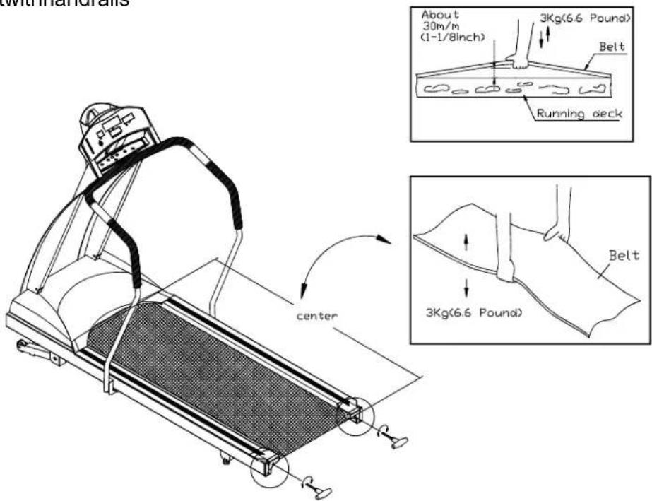
text_image
with mandralls About 30m/m (1-1/8inch) 3Kg(6.6 Pound) Belt Running deck center 3Kg(6.6 Pound) BeltConversely, if there is not enough "give", adjust both rear roller bolts counterclockwise1/2turnatatime.
CAUTION: To avoid injury, special care must be taken when adjusting the running belt. Remove any loose clothing or shoelaces and tie back your hair. Be verycarefultokeepyourfingersoranyotherobjectsclearofthebeltand rollers.
Thetreadmillisdesignedtocarryspecificweightsatspecificspeeds. Thetreadmill willnotstopimmediatelyifanobjectbecomescaughtinthebeltorrollers.
Over tightening of the belt causes damage and premature failure of the precision bearings in the front and rear rollers.
TROUBLESHOOTING:
CAUTION: SHUTOFFUNITANDDISCONNECTACCORDBEFOREMAKING ANYREPAIRSORMODIFICATIONS.
"ERR" messages
Note: If the electronic display shows "E-1, E-3, E-7 or E-10", please turn off the POWERswitchonthefrontofthemachine. Allowtheunittorestfor5 seconds; thenturnonthepowerswitchbeginoperationagain. Ifthe electronics package displays "ERR" again, please refer to the following sectionformoreinformation. OR, pleasecontactyourdealerforfurther instructions.
E-1 Theopticalswitchmountedonthemotorisnotreceivingthesignalreflected from the tachometer wheel. Please contact your dealer.
E-3 Treadmill speed doesn't match the setting. Contact your local dealer for assistance.
E-7 The computer is receiving the signal reflected from VR incorrectly which means the wireshavebeendisconnected. Makesuretheribboncableisconnected securely, orcontactyourdealerforfurtherinformation.
E-10 Treadmill speed doesn't match the setting. Contact your local dealer for assistance.
"ERR" messagesforcontactheartrate
Thiserrormessageisprovidedastowhenrunner usesthefeatureoftheheartrate contact. It doesn't effect the normal variety of functions of this product. When the messagedisappears, youarestillabletocontinuetoyourworkout.
E-12 IftheelectronicsdisplayshowsE-12, thecausesofthisproblemmightbeas belowreasons.
(1) Your heart rate cannot be read out due to the signal strength of your heart rate istooweakoryouhavelowbloodpressure.
(2) Your heart rate cannot be read out due to you did not place hands in steady contactwithsensorswhendetectingyourheartrate.
●Replaceyourhandsafterwettingyourhandsalittlebit. Pleasenotethat placingyourhandsinsteadycontactwithsensorsisstrictlyrequired.
E-12willbeclearedoutafteritflashesorscrolls3timesandtheheartrate willbecome"0" automatically.
Blankdisplay
- IfyouturnonthePOWERswitchandthereisnolight:
a. Checkifthepowercordispluggedsecurelyintothewallsocket.
b. Check that the power switch on the front of the unit is in the "ON" position. The powerswitchshouldbelit.
c. If the power switch is not lit, replace the fuse. Please refer to the ELECTRONICS P ACKAGEANDMOTORFUSE F AILUREsectionformore information.
d. If there is still no display after completing the above steps, please contact your dealerformoreinformation.
- Thepowerswitchislit, butnowordsappearonthedisplay:
a. Makesurethecableconnectorsbothinsidetherightliftpostatthebaseofthe treadmillandatthetopofthepostarefirmlyintheirsockets.
b. If no words appear in the display, then the fuse on the drive board needs to be replaced, please check with your dealer for further information.
IfyouturnonthePOWERswitchandthereisnolight, andnothingdisplaysonthe electronicspackage, thenthefusemustbereplaced.
CAUTION: SHUTOFFTHEUNITANDDISCONNECTACCORDBEFORE MAKINGANYREPAIRSORMODIFICATIONS.
Thefuseholders15amp(100V-120V) / 10amp(200V-240V) fortheelectronics packageandmotorarelocatedonthefrontofthemachine. Pleasedetermineyour area'sstandardvoltagepriortoreplacement.
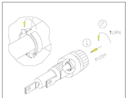
To remove the fuse for the electronics package and motor, push on the fuse holder and then turn the holder counterclockwise and the fuse holder with fuse will protrude. Removethedamaged fuse and insert a new fuse, pushing the fuse and holderin, then turning clockwise to secure the fuse holder. (See Fig 14-1 \~ 14-4)
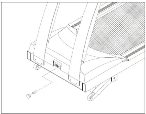
natural_image
Technical line drawing of a mechanical device with no visible text or symbolsFig.14-1

text_image
Technical diagram showing a mechanical component with labeled parts including 'PUSH', 'TURN', and directional arrows indicating motion.Fig.14-2
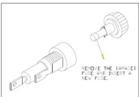
text_image
REMOVE THE DAMAGED FUSE AND INSERT A NEW FUSE.Fig.14-3
text_image
Technical diagram showing mechanical assembly with labeled parts: TURN, PUSH, and directional arrows indicating movement or motion.Fig.14-4
If the unit 'selectronicspackagerefusestorespondafterchangingthefuse, please contact your dealer for more information.
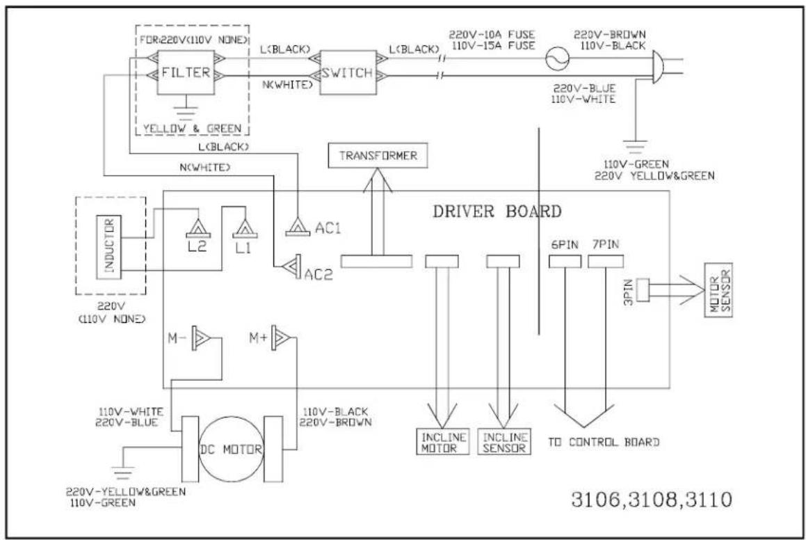
flowchart
graph TD
    A["FOR:220V(110V NONE)"] --> B["FILTER"]
    B --> C["L(BLACK)"]
    C --> D["SWITCH"]
    D --> E["L(BLACK)"]
    E --> F["220V-10A FUSE 110V-15A FUSE"]
    F --> G["220V-BROWN 110V-BLACK"]
    G --> H["220V-BLUE 110V-WHITE"]
    H --> I["110V-GREEN 220V YELLOW&GREEN"]
    I --> J["220V-BLUE"]
    J --> K["AC1"]
    K --> L["AC2"]
    L --> M["AC1"]
    M --> N["TRANSFORMER"]
    N --> O["DRIVER BOARD"]
    O --> P["6PIN 7PIN"]
    P --> Q["MOTOR SENSOR"]
    P --> R["3PIN"]
    R --> S["TO CONTROL BOARD"]
    S --> T["INCLINE SENSOR"]
    T --> U["INCLINE MOTOR"]
    U --> V["DC MOTOR"]
    V --> W["110V-BLACK 220V-BROWN"]
    W --> X["110V-Black 220V-BROWN"]
    X --> Y["220V-BLUE 220V-BLUE"]
    Y --> Z["220V-YELLOW&GREEN 110V-GREEN"]
    Z --> AA["220V (110V NONE)"]
    AA --> AB["L2"]
    AB --> AC["L1"]
    AC --> AD["AC1"]
    AD --> AE["AC2"]
    AE --> AF["TRANSFORMER"]
    AF --> AG["DRIVER BOARD"]
Your Authorized Distributor