1210 - Treadmills SportsArt - Free user manual and instructions
Find the device manual for free 1210 SportsArt in PDF.

User questions about 1210 SportsArt
0 question about this device. Answer the ones you know or ask your own.
Ask a new question about this device
Download the instructions for your Treadmills in PDF format for free! Find your manual 1210 - SportsArt and take your electronic device back in hand. On this page are published all the documents necessary for the use of your device. 1210 by SportsArt.
USER MANUAL 1210 SportsArt
text_image
OWNER'S MANUAL ASSEMBLY INSTRUCTIONSPDF created with FinePrint pdfFactory Pro trial version http://www.pdffactory.com
TABLEOF CONTENTS
- SAFETY GUIDELINES.... 1
- ASSEMBLING YOURTREADMILL InstallationRequirements.... 2 Listofparts.... 4 Stepbystepinstructions.... 5 Stepbystepinstructions (If the unit with handrails).... 7 Floor level adjustment.... 11
- OPERATINGINSTRUCTIONS Safety key.... 12
- UNDERSTANDING THE ELECTRONICS PACKAGE MANUALmode.... 13 PROGRAM mode.... 14 HR 65% mode / HRC 80% mode.... 15
- KEY FUNCTIONS Whateachofthecategoriesmeans.... 16
- RUNNING ON THE TREADMILL.... 18
- GUIDELINESFOREXERCISE How long should I exercise?.... 19 Howoftenshouldlexercise?.... 19
- MAINTAININGYOURTREADMILL Cleaningthetreadmill.... 20 Adjustingtherunningbelt.... 21
- TROUBLE SHOOTING ERRMessage.... 25 Blank display.... 25 Electronicspackageandmotor fusefailure.... 26
- Wiring schematic....27
SAFETY GUIDELINES:
Please read and follow the following safety guidelines:
Before beginning any exercise program, you should consult with your doctor. It is recommended that you undergo a complete physical examination.
- Read this owner's manual carefully and follow the instructions.
- Assemble and operate the treadmill on a solid, level surface. Keep the area behindthetreadmillclear.
- Never allow children on or near the treadmill. The running belt will not stop immediately if any object becomes caught in the belt or rollers.
- Check the treadmill before every use. Make sure all parts are assembled, and all nuts and bolts are tightened. Do not use the treadmill if the unit is disassembled inanyway.
- Keephandsawayfrommoving p arts.
• The weight limit for this treadmill is 275 lb. (125 kg). - Wear proper workout clothing: Do not wear loose clothing. Do not wear shoes with leather soles or high heels. Tie back all long hair.
- Don't rock the unit from side to side. Care should be taken when mounting and dismounting the unit.
- Straddle the machine with your feet on the right and left staging platform before starting t herunningbelt.
- Donotplaceanyliquidsonanypartofthetreadmill.
- To prevent shock, keep all electric components such as the motor, cord, and switchaway from water.
- Turn off the treadmill while adjusting or working near the roller.
- Do not use any accessories that aren't specifically recommended by the manufacturer, these might cause injuries or cause the unit to fail.
- Work within your recommended exercise level, do NOT work to exhaustion.
- If you feel any pain or abnormal sensation, STOP YOUR WORKOUT and consult yourphysicianimmediately.
The treadmill is designed for your use and enjoyment. By following the above precautions and using good judgment and commonsense, you will enjoy safe and pleasurable exercise with this treadmill.
ASSEMBLING YOUR TREADMILL:
Installationrequirements
Read this owner's manual and follow the instructions contained herein.
CAUTION: To avoid back strain, and to ensure safety to the unit and yourself, we suggest you may need a helper to remove the running deck assembly from box.
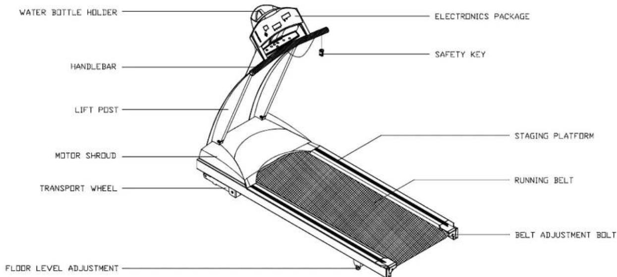
text_image
WATER BOTTLE HOLDER ELECTRONICS PACKAGE HANDLEBAR SAFETY KEY LIFT POST STAGING PLATFORM MOTOR SHROUD RUNNING BELT TRANSPORT WHEEL BELT ADJUSTMENT BOLT FLOOR LEVEL ADJUSTMENTIftheunitwithhandrails
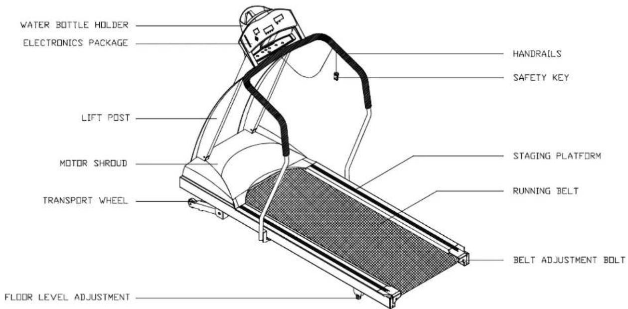
text_image
WATER BOTTLE HOLDER ELECTRONICS PACKAGE HANDRAILS SAFETY KEY LIFT POST STAGING PLATFORM MOTOR SHROUD RUNNING BELT TRANSPORT WHEEL BELT ADJUSTMENT BOLT FLOOR LEVEL ADJUSTMENTListof p arts
Before assembling your treadmill, make sure that you have all the following items:
- O ne s afetykey
- One hex Allen wrench (M6) with T-handle
- One hex Allen wrench (M5) with T-handle
- One hex Allen wrench (M5)
- One hex Allen wrench (M4) with T-handle
- One fuse - 12 amp for 100-120 volt use; 7 amp for 200-240 volt use
- Four M4 x L12 Philips screws - electronics package
- O ne 2 -wayScrewdriver
If any items are missing, contact your authorized service dealer.
IMPORTANT: The packing for this treadmill is designed to protect it during shipment. Please store the original packaging in a safe place in case you need to ship the treadmill in the future.
Stepbystepinstructions
The following step sex explain how to assemble your treadmill. Pleasereade every step thoroughly and follow the directions completely to ensure correct assembly.
-
ThereareimportantpartsenclosedinsideoftheStyrofoam, pleasecheckthe Styrofoamcompartmentsbeforediscarding. Makesureallpackingmaterialsare removedfromthetreadmilldeck.
-
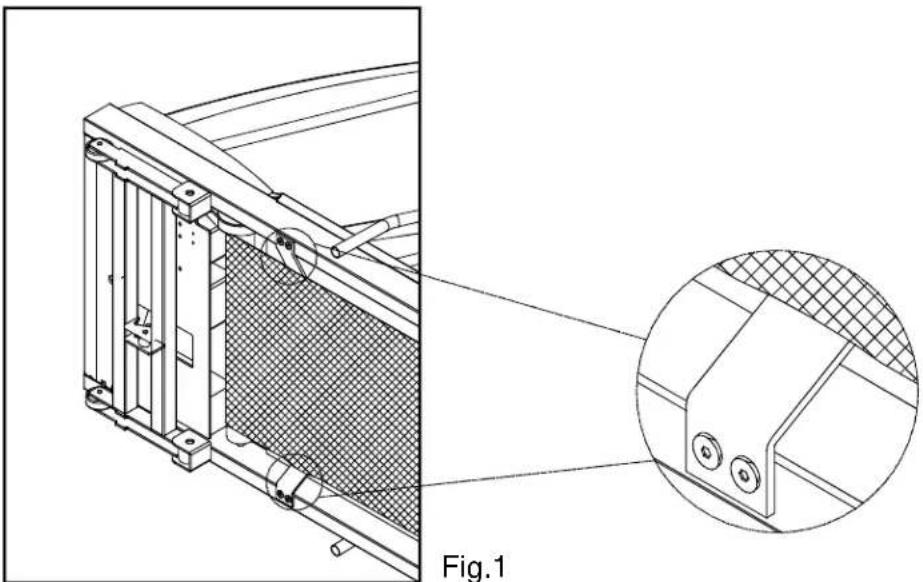
Lay the treadmill on its side. Make sure the running belt is position in the tracks of the two BELT ALIGNMENTROLLERundersideofthemachine (see Fig. 1).

natural_image
Technical line drawing of a mechanical component with a magnified inset showing detail (no text or symbols)-
Then, place the treadmill on a level, flat surface.
-
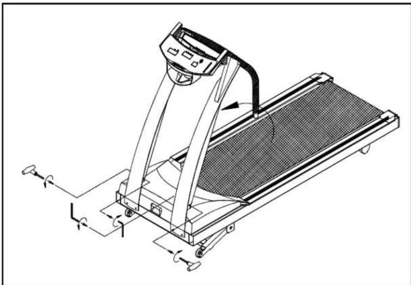
Bring the side post to their upright positions. Attach the screws to the lift post. Do nottightenyet. (seeFig. 2)
natural_image
Technical line drawing of a treadmill with control panel and wheels (no text or symbols)Fig.2
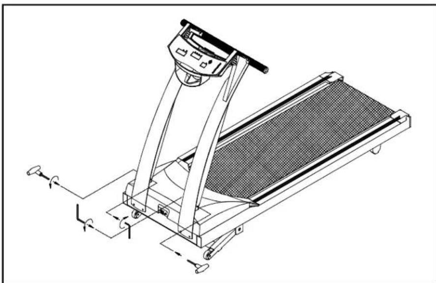
- Using two screws provided on each post. Do not tighten yet. (see Fig. 3)
natural_image
Technical line drawing of a treadmill with adjustable arms and wheels (no text or symbols)Fig.3
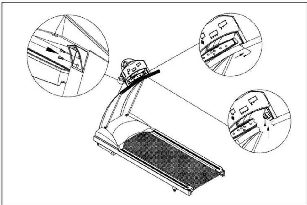
- Insert the electronics display into the slots on the side posts. Use the screwdriver to tighten all screws securely. (See the Fig 4 Highlight). Lastly tighten all the screwsoneachpost.
text_image
Technical diagram of a treadmill with three circular insets showing close-ups of mechanical components and directional arrows.Fig.4
The following steps explain how to assemble your treadmill. Please read every step thoroughly and follow the directions completely to ensure correct assembly.
-
There are important parts enclosed inside of the Styrofoam, please check the Styrofoam compartments before discarding. Make sure all packing materials are removed from the treadmill deck.
-
Lay the treadmill on its side. Make sure the running belt is position in the tracks of the two BELT ALIGNMENT ROLLER underside of the machine (see Fig. 1).
natural_image
Technical line drawing of a mechanical component with a magnified inset showing detail (no text or symbols)-
Then, place the treadmill on a level, flat surface.
-
Bring the side post to their upright positions (including the handlebar and the electronics package). Attach the screws to the lift post. Do not tighten yet. (See Fig. 2)
natural_image
Technical line drawing of a treadmill with attached sensors and control panel (no text or symbols)Fig.2
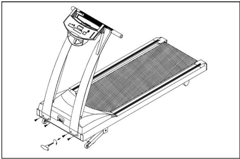
- Using two 5/16" screws provided on each post. Do not tighten yet. (see Fig. 3)

natural_image
Technical line drawing of a treadmill with motion indicators (no text or symbols)Fig.3
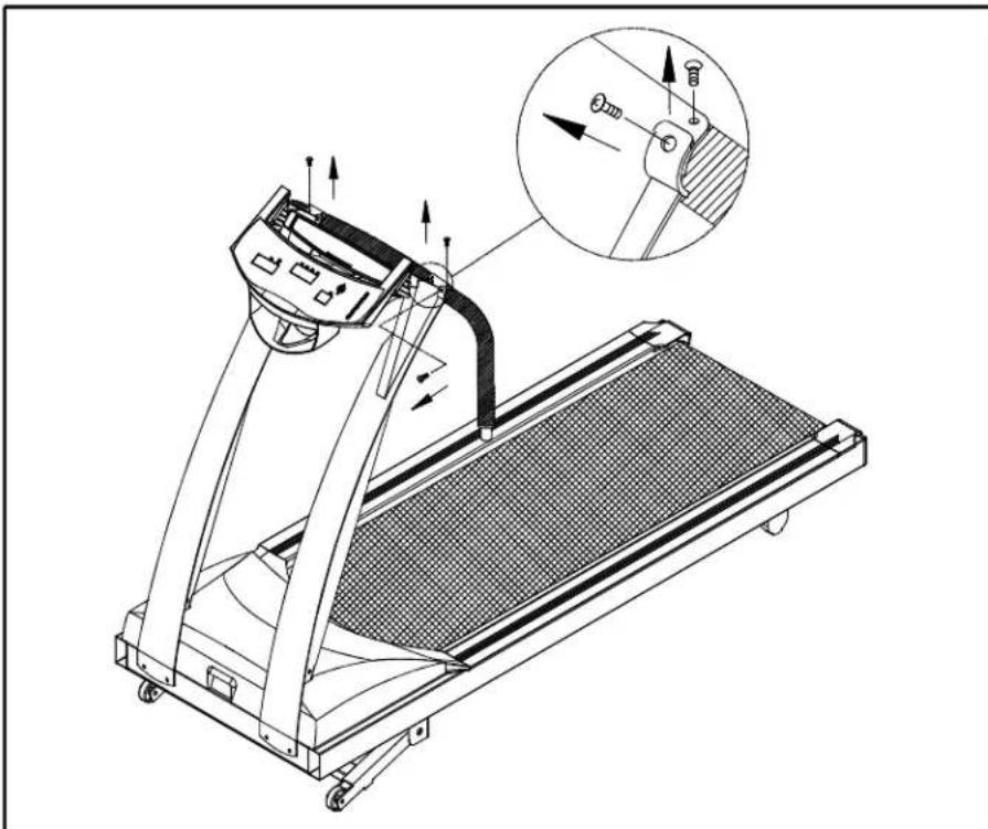
- Loosen the screws of fixing the handlebar and remove the steel plate. (see Fig. 4)
natural_image
Technical line drawing of a treadmill with an inset showing mechanical components (no text or symbols)Fig.4
Please note: The screws to handlebar (Fig.4) are special provided by manufacturer. Do not attempt to substitute any other screws. Any questions, please contact your dealer.
- Turn up the handlebar and fasten the screws. Do not tighten yet. Make sure to assemble the handlebartotheliftpostcorrectly. R to Rwhicharemarkedonthe handlebarandliftpostrespectively. (seeFig. 5)
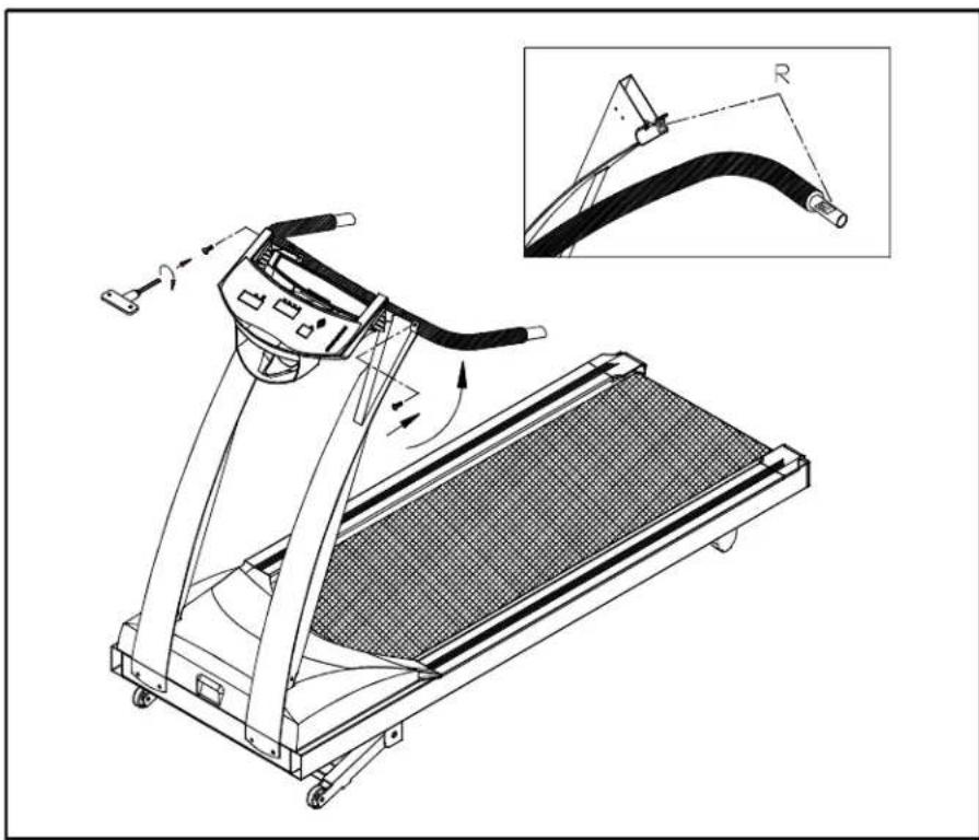
natural_image
Technical line drawing of a treadmill with an inset showing the cable being adjusted (no text or symbols present)Fig.5
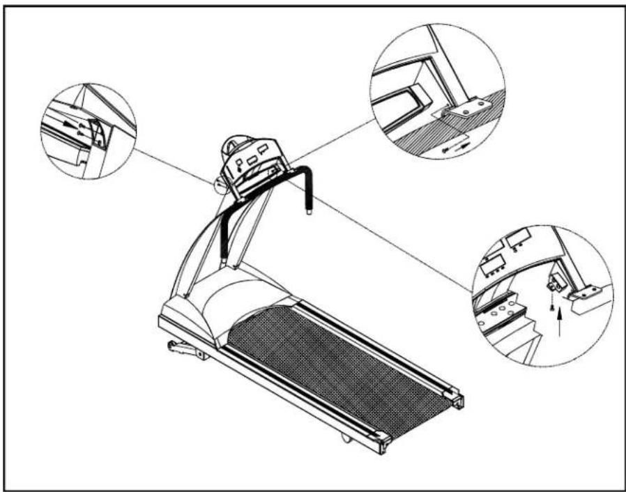
- Insert the electronics display into the slots on the side posts. Use the screwdriver totightenallscrewssecurely(seetheFig 6 Highlight). Lastlytightenallthe screwsoneachpost.
natural_image
Technical illustration of a treadmill with three close-up views showing mechanical components (no text or symbols)Fig.6
- Insert the two handrails into the handlebars and then fasten the screws provided. Lastly secure the handrail clamp by fastening the screws (see Fig. 7).

natural_image
Technical line drawing of a treadmill with attached components and three inset views showing assembly details (no text or symbols present)Fig.7
Please note: The screws to the handrail clamp (Fig.7) are special provided by manufacturer. Do not attempt to substitute any other screws. Any questions, please contact your dealer.
- Secure the screws in front of the lift posts and handlebar tightly, Secure the screws to the lift posts tightly (see Fig. 8).

text_image
Technical diagram of a treadmill with labeled parts and motion arrows indicating movement pathsFig.8
Floorleveladjustment
If the treadmill is not steady on your floor, turn the floor level adjustment on the rear feet leg of the treadmill. Raise or lower the floor level adjustment to steady your treadmill(seeFig. 9).

natural_image
Technical line drawing of a mechanical component with a rotating base and grid-patterned panel (no text or symbols)Fig.9
Your treadmill is assembled and ready to use.
OPERATINGINSTRUCTIONS
CAUTION: DONOTSTANDONTHEBELTWHENSTARTING.
Safetykey
Thesafetykeyisrequiredtooperatethetreadmill(seeFig.10). Thesafetykey shouldbeusedasanemergencystopbyclippingthecordtoyourexerciseclothing. Besuretostoreitin a safeplacetoavoidusebychildrenorpersonsunfamiliarwith thistreadmill.
Turnonthepowerswitchlocatedonthefrontofthetreadmill. Insertthesafetykey intothe"SAFETYKEY" positiononthemiddlesocketoftheelectronicspackagein orderfortheunittofunction.

natural_image
Technical line drawing of a mechanical device with no visible text or symbolsFig.10
UNDERSTANDING THE ELECTRONICS PACKAGE
CAUTION: DO NOT STAND ON THE BELT WHEN STARTING. Straddle the belt with your feet on the right and left staging platforms.
A. After your turn on the power switch located on the front of the treadmill, the treadmill will not function without the safety key in place on the "SAFETY KEY" position of the electronics package.
B. The display shows — — — — —, that means to insert the safety key into its position.
C. After you insert the safety key in place, the "User" light flashes, and the display above User shows 01 \~ 04, that is User 1 \~ 4. You may press Speed ▲▼ to start the unit or followthebelowsteps.
D. Use the ▼ or ▲ keys to select from user 1 through user 4. Once you have made your choice, press "Enter". The user light stops flashing, and the "Weight" light flashes. The display above Weight shows Weight, you can adjust it by pressing ▼ or ▲ keys, and it will change the weight 10LB or 5KG each time. Press "Enter". The electronics package automatically recalls the program that was used last.
MANUALmode:
A. When the MANUAL LED is lit, you are in the MANUAL mode.
B. Press the SPEED ▼ or ▲ keys, and this will start the motor. The speed range is 0-10 MPH (0-16 KPH). Press speed ▲ key to increase and press ▼ key to decrease the speed.
C. Press the INCLINE ▼ or ▲ keys, and this will raise and lower the treadmill. The INCLINErangeis 0-12%.
D. Press the MODE key, and this will scroll you through the different modes on the display window. With each press of the MODE key, the display will alternately show TIME, DIST(DISTANCE), CAL(CALORIES), HR or SCAN.
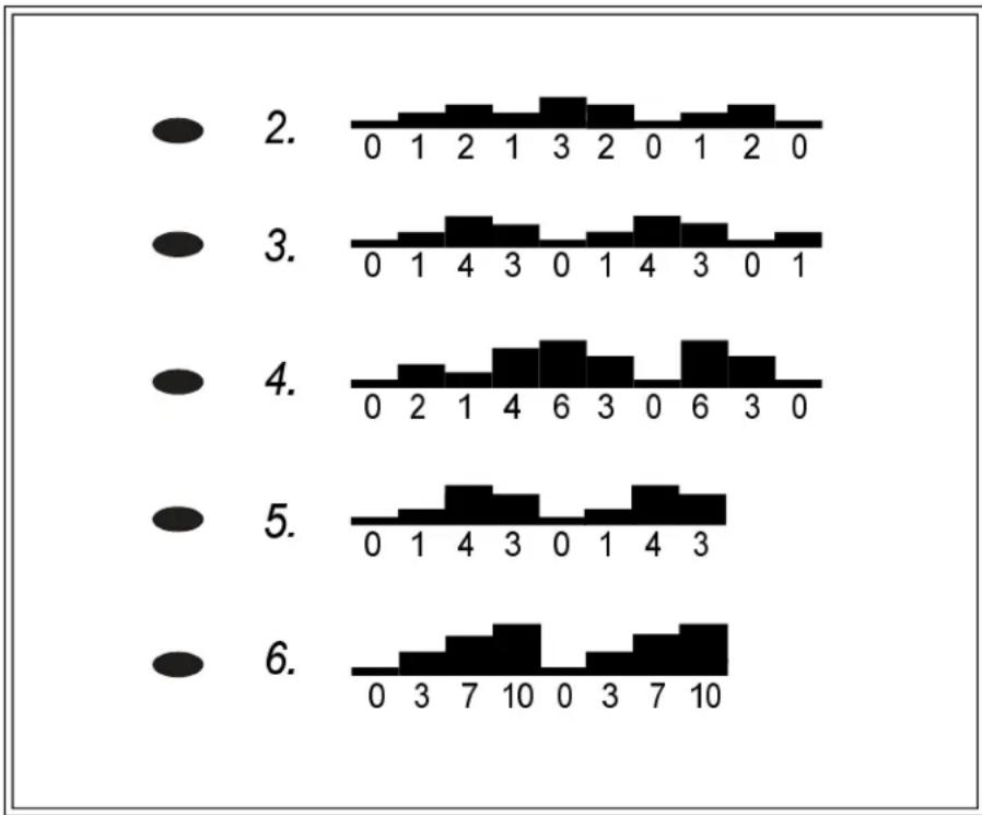
PROGRAMmode
A. There are a total of five (5) programs in this machine.
B. PresstheScrollkeytochooseanyprogram, andyouareintheprogrammode.
ThecourseprofileforeachPROGRAMisasfollows:
bar
| Category | Value | |---|---| | 2. | 0 | | 2. | 1 | | 2. | 2 | | 2. | 1 | | 2. | 3 | | 2. | 2 | | 2. | 0 | | 2. | 1 | | 2. | 2 | | 2. | 0 | | 3. | 0 | | 3. | 1 | | 3. | 4 | | 3. | 3 | | 3. | 0 | | 3. | 1 | | 3. | 4 | | 3. | 3 | | 3. | 0 | | 3. | 1 | | 4. | 0 | | 4. | 2 | | 4. | 1 | | 4. | 4 | | 4. | 6 | | 4. | 3 | | 4. | 0 | | 4. | 6 | | 4. | 3 | | 4. | 0 | | 5. | 0 | | 5. | 1 | | 5. | 4 | | 5. | 3 | | 5. | 0 | | 5. | 1 | | 5. | 4 | | 5. | 3 | | 6. | 0 | | 6. | 1 | | 6. | 4 | | 6. | 3 | | 6. | 0 | | 6. | 1 | | 6. | 4 | | 6. | 3 | | 6. | 7 | | 6. | 10 | | 6. | 0 | | 6. | 3 | | 6. | 7 | | 6. | 10 |C. When you have chosen the one you want, press the ENTER key. The TIME LED flashes. Usetheor keyst set TIME, thenpressENTER.
Thenyoustarttheunitusingthespeedorkeys. During these programs, you control the speed, and the unit will automatically switch between elevation percentages, giving you the feeling of running on hills or level ground.
UsetheMODEkeytoswitchthesmallercenterdisplaybetweenTIME, DIS, CAL, HRorSCAN.
WhenyourdesiredTIMEisreached, a beeptonewillsoundfor10seconds, after whichthemachinewillbegintocountupagain.
HR 65% mode / HRC 80% mode (The function is available while the unit is with PolarReceiver.)
A. PressthescrollkeytoHRC65% or HRC80%.
B. Press ENTER, then the AGE LED flashes to remind you to input your age. Press ▼ or ▲ key to input it, while the Target HR is lit, the display shows the target heartrateaccordingtoyourinputage.
C. Input your age, press ENTER. The Target HR is still lit, and the display flashes the targetheartrate. Useorkeytoadjustit, butyoucannotincrease the prescribedlimit. ThenpressENTER.
D. The TIME LED flashes. Use ▼ or ▲ key to input the time you want to spend in your TargetZone. ThenpressENTER.
E. The MAX SPEED flashes. Use speed ▼ or ▲ key to set your desired MAX SPEED, the motor start working. While you input and confirm the MAX SPEED, after3 seconds, the displayshowsthecurrentspeedautomatically.
F. Every 4 seconds, the display switches between Target HR, current HR, and Time. Every8seconds, itswitchesbetweenMAX SPEEDandcurrentspeed.
KEYFUNCTIONS:
SCROLL: Use the Scroll key to choose the desired course, like Manual, Program, and HRC.
SPEED ▼▲ : Use the speed ▼▲ key to adjust your desired speed. The speed rangeforthetreadmillisfrom0-10mph(0-16kph). Pressthespeed ▲ keytoincreasethespeedandpresstheSpeedkeyto ▼ decreasethespeed.
INCLINE ▼▲ : Use the INCLINE ▼▲ key to raise or lower the treadmill. The incline rangeforthetreadmillisfrom0%-12%.
MODE: Press the mode key, and this will scroll you through the different modes. With each press of the MODE key, the display will alternately show TIME, DIST (Distance), CAL(Calories), HRorSCAN.
▼▲ key: These keys are used to choose the desired TIME or DISTANCE.
SAFETY KEY: For safety, one has to insert the safety key in its place to operate the treadmill. If not, the unit won't work.
(HOLD TO RESET)
STOP : Press STOP key, this treadmill will come to stop running gradually.
When this treadmill stops running, hold STOP key as a function of RESET, andalldataisclearedupaccordingly.
ENTER: Usetheenterkeytoconfirmyourinput.
Whateachofthecategoriesmeans:
TIME: The range available in TIME mode is 00:00-99:59 minutes. Use the MODE key to select the time mode. When TIME LED is lit in the display, use the ▼▲ keystoadjustthedesiredtime.
TheelectronicspackagewillBEEP for3secondswhenyourdesiredtimeis reached, thenwillstarttocountupifyouworkoutcontinues. Eachpressof thekeychangethetimeby 1 minute.
DIST: The distance of the treadmill will register goes from 0-99.99 miles or 0-999.9 kilometers. Use the MODE key to select the DIST mode. When DIST LED is lit in the display, use the ▼▲ keys to adjust the desired distance.
Each press of the key changesthedistance by 0.05 mile or 0.1 km.
The electronicspackagewillBEEPfor3secondswhenyourdesireddistance isreached, thenwillstarttocountupifyouworkoutcontinues.
CAL: Thisreadoutgivesyoutheamountofcaloriesburned, therangeofcaloriesis from0-999.9CAL.
SCAN: The SCAN will result in the display alternation between Modes readouts every 4 seconds.
HR: Thisreadoutgivesyoutheheartrateofyourworkout.
RUNNING ONTHETREADMILL:
Now, you have become familiar with your treadmill's operation and are ready to exercise:
- Turn the power switch ON, and place the safety key on the "SAFETY KEY" position.
- Straddlethebeltwithyourfeetontherightandleftstagingplatforms. Clipthe safetykeytoyourexciseclothingatyourwaistline.
- Straddle the belt, balancing one hand on the handrail. Press SPEED key to start the treadmill. Adjust the speed ▲ key until you reach 1.5-2.0 MPH / 2.5-3.5 KPH, a comfortable walking speed. With both hands on the handrails, place one foot, thentheotheronthetreadmill, andwalkforafew minutestogetcomfortable with yourmachine.
- After you are walking in an easy, relaxed, and steady fashion, release your grip on the handrails, and let your arm swing freely and naturally.
- When you feel comfortable walking, you may wish to jog. Hold the handrail with onehand, using your other hand to increase the speed.
- Remember to hold the handrail when using the control panel on the electronics package. Holding the handrail with one hand will help to maintain your balance, especially when slowing down or stopping. Also, remember to hold onto the handrail whendismounting.
- When you have finished your workout, movethesafety key from the "SAFETY KEY" position. Always remember to cool down after your workout before completely stopping.
GUIDELINESFOREXERCISE
Howlongshould I exercise?
Thedurationofyourexcisesessionisdependentonyourfitnesslevel. Ingeneral, itisrecommendedthatyoumaintainyourheartrateinthetrainingzoneforatleast 10 minutes to realize an aerobic benefit. As your fitness level increases, you will be abletomaintainyourheartrateinthetrainingzoneforlongerperiods, usually between20and30minutes.
Whenfirststartingyourworkout, usethefirstseveralminutestowarmup, then slowlyincreaseyourworkloadtobringyourheartrateintoyourspecifictraining zone. At the end of your workout, gradually decrease your workload, then exercise lightlyasa"cooldown".
Howoftenshouldlexercise?
Aerobic exercises, to achieve the greatest benefits, should be performed 3-5 times a week. It is important to allow sufficient time, at least 24 hours, for your body to recoverafterexercise.
MAINTAININGYOURTREADMILL
Your treadmill relies on low friction for peak performance. The treadmill's low friction operation is dependent on keeping the unit as clean as possible. See "Cleaning the Treadmill" form more information.
Properbeltalignmentisalsoimportantforproperoperationofthetreadmill. See "AdjustingtheRunningBelt" formoreinformation.
Cleaningthetreadmill
CAUTION: TurnoffunitanddisconnectACcordbeforecleaning.
Regularcleaningisrecommendedtokeepyourtreadmillrunningatpeak Performance.
Before your workout, use a dry cloth to clean the staging platform, exposed slider deck, and underthebeltasfarasyoueasilyreach. This removesanydirtordust which might enter the slider area and compromise the unit's running efficiency.
To clean the plastic parts, use a mild detergent and make sure the unit is completely dry before operating. On the running surface, use a soft nylon scrub brush.
Donotusewatertocleanthebeltorrunningsurface, ortocleantheelectronics package. Should water, for some reason, get on the electronics package, immediatelyblowdrytheelectronicspackage.
It is recommended that you keep all liquids away from the unit during operation. Spillage of liquids onto or into them, machine will void the warranty.
Adjustingtherunningbelt
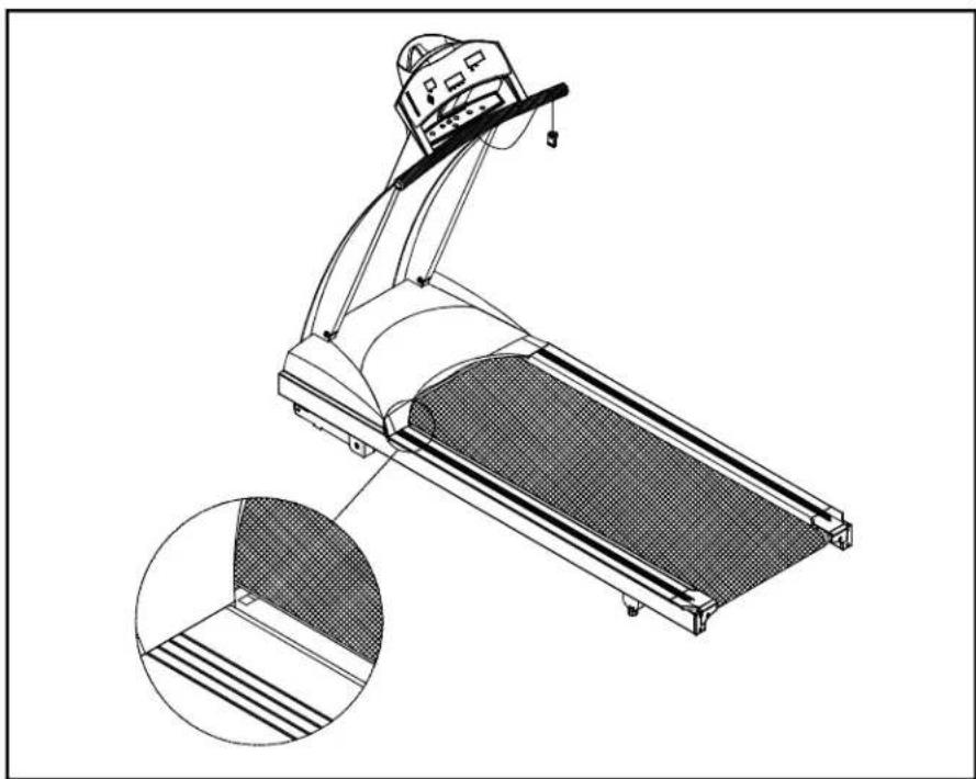
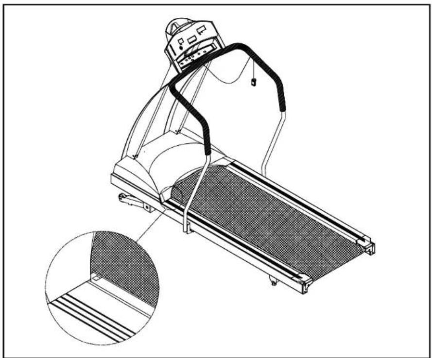
Your treadmill comes with a belt alignment gauge located on the deck. (see Fig.11) Theedgeoftherunningbeltshouldbeinthemiddleofthegreenportionofthe gauge. If the belt edge is in the green area, the belt does not need adjusting. If the beltedgeisintheredportion, thebeltneedsadjustingimmediately.
natural_image
Technical line drawing of a treadmill with mesh cover and inset detail (no text or symbols)Fig.11
Iftheunitwithhandrails
natural_image
Line drawing of a treadmill with mesh pattern and inset detail (no text or symbols)The belt is properly aligned at the factory. However, during shipping and handling or by use on an uneven surface, the belt may move off center. Therefore, it is important that you check the belt's alignment before using the treadmill.
The correct alignment of the running belt is critical for the smooth operation of the treadmill.
CAUTION: DO NOT ALLOW ANYONE TO WALK ON RUNNING BELT DURING THIS PROCEDURE.
Failure to realign the belt could result in tearing or fraying of the belt, which is not coveredinthewarranty. Pleasefollowtheadjustmentprocedurelistedbelow:
- Turn on the power switch located on the front of machine. Insert the SAFETY KEY ontheitsposition.
- Press the SPEED ▲ key to increase the speed until the speed registers 2.0mph / 3.2kphonthedigitaldisplay.
- While the unit is running at 2.0mph/3.2kph, determine where the belt is in relation tothebeltalignmentgauge.
- Should your belt be in the wrong color range, follow the steps below to return the belttothe"safetyzone":
- If the belt is in the left red zone: Turn the left belt adjustment bolt located at the rear of the treadmill clockwise 1/4 turn at a time, using the hex Allen wrench. Thenturntherightbeltadjustmentboltcounterclockwise1/4turn. Letthe treadmill run 30 seconds, then check the position of the belt in the color gauge. If thebeltstillhasnotreturnedtothegreensafetyzone, repeatwithanother 1/4 turnuntilthebelthasreturnedtothemiddleofthegreenarea. Donotturn adjustingboltmorethan1/4turnatonetime.
If the belt is on the edge of the greencolor, please adjust it so it is in them middle of the green color. You may turn the adjustment nut less than 1/4 turn at one time. - Conversely, if the belt is in the right red zone, turn the right belt adjustment nut clockwise1/4turn, thenturntheleftadjustmentboltcounterclockwise1/4turn. Thenletthetreadmillrunatleast30seconds, checkthepositionofthebeltinthe color gauge. If it still has not returned to the green safety zone, repeat with another 1/4turnuntilthebelthasreturntothemiddleofthegreenarea. Donot turnadjustingboltmorethan1/4turnatonetime.
- When the belt is back in the green "safety zone", you can continue your regular useofthetreadmill. Slowlyincreasethespeedoftheunitto5.5MPH(9KPH), andletitrunfor atleast45seconds.
Periodically monitor the position of the belt to ensure peak performance:
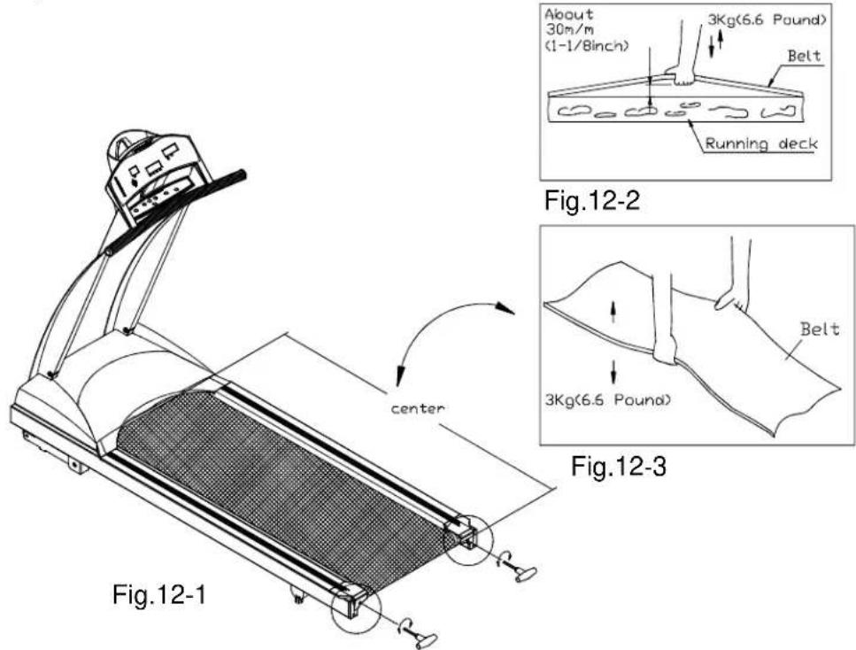
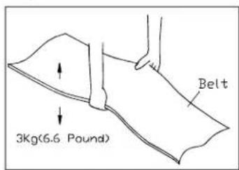
When you are using the treadmill, if you feel a pause in the belt with each foot plant, the belt is too loose. Stop the machine to check the belt tension, pull the running belt up in the middle (see Fig. 12-1 & 12-2). There should be about 30 m/m (1 1/8") or 3 kgs of "give" in the belt (see Fig. 12-3). If there is too much, adjust both rear roller bolts clockwise 1/2 turn at a time (see Fig. 12-1). Then, check the belt tension again, if more adjusting is required, give both adjusting bolts another slight turn. Do not adjust over 2 full turns.
text_image
About 30m/m (1-1/Binch) 3Kg(6.6 Pound) Belt Running deck Fig.12-2 center Fig.12-3 3Kg(6.5 Pound) Belt Fig.12-1Iftheunitwithhandrails

text_image
PDP center Fig.12-1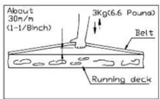
text_image
About 30m/m (1-1/8inch) 3Kg(6.6 Pound) Belt Running deckFig.12-2
text_image
3Kg(6.6 Pound) BeltFig.12-3
Conversely, if there is not enough "give", adjust both rear roller bolts counterclockwise1/2turnatatime.
CAUTION: To avoid injury, special care must be taken when adjusting the running belt. Remove any loose clothing or shoelaces and tie back your hair. Be very careful to keep your fingers or any other objects clear of the belt androllers.
The treadmill is designed to carry specific weights at specific speeds. The treadmill will not stop immediately if an object becomes caught in the belt or rollers.
Over tightening of the belt causes damage and premature failure of the precision bearings in the front and rear rollers.
TROUBLESHOOTING:
CAUTION: SHUTOFFUNITANDDISCONNECTACCORDBEFOREMAKING ANYREPAIRSORMODIFICATIONS.
"ERR" messages
Note: If the electronic display shows "E-1, E-3, E-7 or E-10", please turn off the POWERswitchonthefrontofthemachine. Allowtheunittorestfor5 seconds; thenturnonthepowerswitchbeginoperationagain. Shouldthe electronics package display "ERR" again, please refer to the following section formoreinformation. OR, pleasecontactyourdealerforfurtherinstructions.
E-1 Theopticalswitchmountedonthemotorisnotreceivingthesignalreflected from the tachometer wheel. Please contact your dealer.
E-3 The user is running faster than the belt. Please turn the POWER switch off, allow them machinetorest for 5 seconds, thentry normal use again.
E-7 The computer is receiving the signal reflected from VR incorrectly which means the wireshavebeendisconnected. Makesuretheribboncableisconnected securely, orcontactyourdealerforfurtherinformation.
E-10 Thetreadmillsuddenlyspeedsuptomaximumspeedwhileyouareusingit andshutsoff. Discontinueuseandcontactyourdealerforfurtherinformation immediately.
Blankdisplay
- IfyouturnonthePOWERswitchandthereisnolight:
a. Checkifthepowercordispluggedsecurelyintothewallsocket.
b. Check that the power switch on the front of the unit is in the "ON" position. The powerswitchshouldbelit.
c. If the power switch is not lit, replace the fuse. Please refer to the ELECTRONICS PACKAGE AND MOTOR FUSE FAILURE section for more information.
d. If there is still no display after completing the above steps, please contact your dealerformoreinformation.
- Thepowerswitchislit, butnowordsappearonthedisplay:
a. Makesurethecableconnectorsbothinsidetherightliftpostatthebaseofthe treadmillandatthetopofthepostarefirmlyintheirsockets.
b. If no words appear in the display, then the fuse on the drive board needs to be replaced, please check with your dealer for further information.
Electronicspackageandmotorfusefailure
IfyouturnonthePOWERswitchandthereisnolight, andnothingdisplaysonthe electronicspackage, thenthefusemustbereplaced.
CAUTION: SHUTOFFTHEUNITANDDISCONNECTACCORDBEFORE MAKINGANYREPAIRSORMODIFICATIONS.
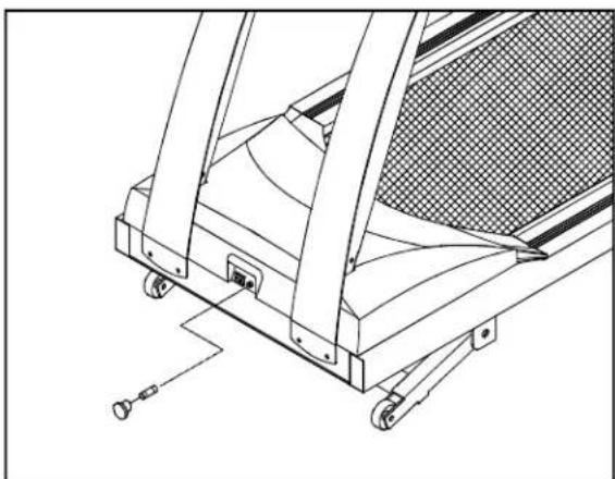
Thefuseholders12amp(100V-120V) / 7 amp(200V-240V) fortheelectronics packageandmotorarelocatedonthefrontofthemachine. Pleasedetermineyour area'sstandardvoltagepriortoreplacement.
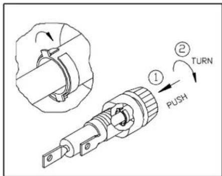
To remove the fuse for the electronics package and motor, push on the fuse holder and then turn the holder counterclockwise and the fuse holder with fuse will protrude. Removethedamaged fuse and insert a new fuse, pushing the fuse and holder in, then turning clockwise to secure the fuse holder. (See Fig 13-1 \~ 13-4)
natural_image
Technical line drawing of a mechanical device with wheels and structural components (no text or symbols)Fig.13-1
text_image
Technical diagram showing a mechanical component with labeled parts and directional arrows indicating 'TURN' and 'PUSH'Fig.13-2

text_image
REMOVE THE DAMAGED FUSE AND INSERT A NEW FUSE.Fig.13-3

text_image
Technical diagram showing a mechanical component with labeled parts and directional arrows indicating 'TURN' and 'PUSH' operations.Fig.13-4
If the unit's electronics package refuses to respond after changing the fuse, please contact your dealer form more information.
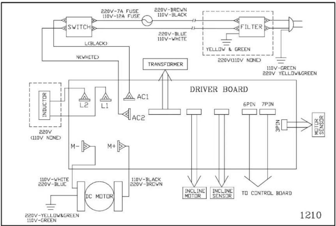
WiringSchematic:
flowchart
graph TD
    A["SWITCH"] --> B["220V-7A FUSE 110V-12A FUSE"]
    B --> C["220V-BROWN 110V-BLACK"]
    C --> D["FILTER"]
    D --> E["110V-GREEN 220V YELLOW&GREEN"]
    D --> F["110V-Black 220V-BROWN"]
    G["INDUCTOR 220V (110V NONE)"] --> H["L2 L1"]
    H --> I["AC1 AC2"]
    I --> J["TRANSFORMER"]
    K["DC MOTOR 110V-BLACK 220V-BROWN"] --> L["M+"]
    M["INCLINE SENSOR 6PIN 7PIN"] --> N["TO CONTROL BOARD 3PIN"]
    O["INCLINE MOTOR"] --> P["DRIVER BOARD"]
    Q["220V-YELLOW&GREEN 110V-GREEN"] --> R["DC MOTOR"]
    S["N(WHITE)"] --> T["L(BLACK)"]
    U["220V-BLUE 220V-BLUE"] --> V["AC1"]
    W["3PIN"] --> X["MOTOR SENSOR"]
    Y["220V (110V NONE)"] --> Z["AC2"]
    AA["5PIN"] --> AB["6PIN"]
    AC["110V-GREEN"] --> AD["5PIN"]
    AE["220V YELLOW & GREEN"] --> AF["5PIN"]