WRT54GR - Router LINKSYS - Free user manual and instructions
Find the device manual for free WRT54GR LINKSYS in PDF.

User questions about WRT54GR LINKSYS
0 question about this device. Answer the ones you know or ask your own.
Ask a new question about this device
Download the instructions for your Router in PDF format for free! Find your manual WRT54GR - LINKSYS and take your electronic device back in hand. On this page are published all the documents necessary for the use of your device. WRT54GR by LINKSYS.
USER MANUAL WRT54GR LINKSYS
A Division of Cisco Systems, Inc.

natural_image
Exterior view of a wireless router device (no visible text or symbols on body)2,4 GHz 802.11g
WIRELESS
Wireless-G
Broadband Router with RangeBooster
User Guide
Cisco SYSTEMS

Model No. WRT54GR (EU/LA/UK)
Wireless-G Broadband Router with RangeBooster
Copyright and Trademarks
Specifications are subject to change without notice. Linksys is a registered trademark or trademark of Cisco Systems, Inc. and/or its affiliates in the U.S. and certain other countries. Copyright © 2006 Cisco Systems, Inc. All rights reserved. Other brands and product names are trademarks or registered trademarks of their respective holders.
How to Use This User Guide
This User Guide has been designed to make understanding networking with the Wireless-G Broadband Router with RangeBooster easier than ever. Look for the following items when reading this User Guide:

This checkmark means there is a note of interest and is something you should pay special attention to while using the Wireless-G Broadband Router with RangeBooster.

This exclamation point means there is a caution or warning and is something that could damage your property or the Wireless-G Broadband Router with RangeBooster.

This question mark provides you with a reminder about something you might need to do while using the Wireless-G Broadband Router with RangeBooster.
In addition to these symbols, there are definitions for technical terms that are presented like this:
word: definition.
Also, each figure (diagram, screenshot, or other image) is provided with a figure number and description, like this:
Figure 0-1: Sample Figure Description
Figure numbers and descriptions can also be found in the "List of Figures" section in the "Table of Contents".
Wireless-G Broadband Router with RangeBooster
\*
Chapter 1: Introduction.... 1
Welcome 1
What's in this User Guide? 2
Chapter 2: Planning Your Wireless Network .... 4
Network Topology 4
Ad-Hoc versus Infrastructure Mode 4
Network Layout....4
Chapter 3: Getting to Know the Wireless-G Broadband Router
with RangeBooster 6
The Back Panel 6
The Front Panel....7
Chapter 4: Connecting the Wireless-G Broadband Router
with RangeBooster 8
Hardware Installation for Connection to Your Broadband Modem 8
Chapter 5: Configuring the Wireless-G Broadband Router
with RangeBooster 10
Overview 10
The Setup Tab - Basic Setup. 11
The Setup Tab - DDNS. 15
The Setup Tab - MAC Address Clone. 16
The Setup Tab - Advanced Routing. 17
The Wireless Tab - Basic Wireless Settings 18
The Wireless Tab - Wireless Security 19
The Wireless Tab - Wireless MAC Filter 22
The Wireless Tab - Advanced Wireless Settings.... 23
The Security Tab - Firewall 25
The Security Tab - VPN Passthrough. 26
The Access Restrictions Tab - Internet Access Policy.... 26
The Applications and Gaming Tab - Single Port Forwarding.... 28
The Applications and Gaming Tab - Port Range Forwarding. 29
The Applications & Gaming Tab - Port Range Triggering 30
The Applications and Gaming Tab - DMZ 30
Wireless-G Broadband Router with RangeBooster
The Administration Tab - Management.... 31
The Administration Tab - Log 33
The Administration Tab - Diagnostics 34
The Administration Tab - Factory Defaults 35
The Administration Tab - Firmware Upgrade 35
The Status Tab - Router 36
The Status Tab - Local Network 37
The Status Tab - Wireless Network.... 37
Appendix A: Troubleshooting 38
Common Problems and Solutions 38
Frequently Asked Questions 46
Appendix B: Wireless Security 53
Security Precautions 53
Security Threats Facing Wireless Networks 53
Appendix C: Upgrading Firmware.... 56
Appendix D: Windows Help 57
Appendix E: Finding the MAC Address and IP Address for
Your Ethernet Adapter.... 58
Windows 98SE or Me Instructions.... 58
Windows 2000 or XP Instructions .... 58
For the Router's Web-based Utility 59
Appendix F: Glossary 60
Appendix G: Specifications 65
Appendix H: Warranty Information.... 67
Appendix I: Regulatory Information.... 68
Appendix J: Contact Information 79
Wireless-G Broadband Router with RangeBooster
★▲▼ □※ ◆※◆□※▲
Figure 3-1: The Router's Back Panel 6
Figure 3-2: The Router's Front Panel 7
Figure 4-1: Connecting Your Internet Connection....8
Figure 4-2: Connecting Your Network Devices 9
Figure 4-3: Connecting the Power 9
Figure 5-1: Password Screen 10
Figure 5-2: Setup Tab - Basic Setup....11
Figure 5-3: DHCP Connection Type....11
Figure 5-4: Static IP Connection Type....11
Figure 5-5: PPPoE Connection Type 12
Figure 5-6: PPTP Connection Type 12
Figure 5-7: HeartBeat Signal Connection Type....13
Figure 5-8: Optional Settings 13
Figure 5-9: Router IP....13
Figure 5-10: DHCP Server Settings.... 14
Figure 5-11: Static DHCP Client List 14
Figure 5-12: DHCP Client Table.... 14
Figure 5-13: Time Setting....14
Figure 5-14: Setup Tab - DDNS.com.... 15
Figure 5-15: Setup Tab - TZO.com 15
Figure 5-16: Setup Tab - MAC Address Clone. 16
Figure 5-17: Setup Tab - Advanced Routing. 17
Figure 5-18: Setup Tab - Routing Table 17
Figure 5-19: Wireless Tab - Basic Wireless Settings ..... 18
Figure 5-20: Wireless Tab - Wireless Security (WEP) 19
Figure 5-21: Wireless Tab - Wireless Security (WPA-Personal) 19
Figure 5-22: Wireless Tab - Wireless Security (PSK2) 20
Figure 5-23: Wireless Tab - Wireless Security (PSK2-Mixed)....20
Figure 5-24: Wireless Tab - Wireless Security (WPA Enterprise) 20
Figure 5-25: Wireless Tab - Wireless Security (PSK2 + RADIUS) ..... 21
Figure 5-26: Wireless Tab - Wireless Security (RADIUS). 21
Wireless-G Broadband Router with RangeBooster
Figure 5-27: Wireless Tab - Wireless MAC Filter 22
Figure 5-28: Wireless Client List.... 22
Figure 5-29: Wireless Tab - Advanced Wireless Settings.... 23
Figure 5-30: Security Tab - Firewall 25
Figure 5-31: Security Tab - VPN Passthrough. 26
Figure 5-32: Access Restrictions Tab - Internet Access Policy. 26
Figure 5-33: Internet Policy Summary 27
Figure 5-34: List of PCs. 27
Figure 5-35: Applications and Gaming Tab - Single Port Forwarding. 28
Figure 5-36: Applications and Gaming Tab - Port Range Forward 29
Figure 5-37: Applications and Gaming Tab - Port Triggering 30
Figure 5-38: Applications and Gaming Tab - DMZ 30
Figure 5-39: Administration Tab - Management. 31
Figure 5-40: Administration Tab - Log 33
Figure 5-41: Administration Tab - Incoming Log 33
Figure 5-42: Administration Tab - Diagnostics 34
Figure 5-43: The Ping Test 34
Figure 5-44: The Traceroute Test 34
Figure 5-45: Administration Tab - Factory Defaults 35
Figure 5-46: Administration Tab - Firmware Upgrade 35
Figure 5-47: Status Tab - Router 36
Figure 5-48: Status Tab - Router with PPPoE IP Connection 36
Figure 5-49: Status Tab - Local Network 37
Figure 5-50: DHCP Clients Table....37
Figure 5-51: Status Tab - Wireless Network. 37
Figure C-1: Upgrade Firmware 56
Figure E-1: IP Configuration Screen 58
Figure E-2: MAC Address/Adapter Address....58
Figure E-3: MAC Address/Physical Address 58
Figure E-4: MAC Address Filter List 59
Figure E-5: Wireless Client List. 59
Figure E-6: MAC Address Cloning 59
Wireless-G Broadband Router with RangeBooster

Welcome
Thank you for choosing the Linksys Wireless-G Broadband Router with RangeBooster. The Wireless-G Broadband Router with RangeBooster will allow you to network wirelessly better than ever, sharing Internet access, files and fun, easily and securely and with a greater range of up to twice as far as standard Wireless-G.
How does the Wireless-G Broadband Router with RangeBooster do all of this? A router is a device that allows access to an Internet connection over a network. With the Wireless-G Broadband Router with RangeBooster, this access can be shared over the four switched ports or via the wireless broadcast at up to 11Mbps for Wireless-B or up to 54Mbps for Wireless-G.
Use the WPA standard to secure your wireless network while the whole network is protected through a Stateful Packet Inspection (SPI) firewall and Network Address Translation (NAT) technology. You can also access the Router's features through the easy-to-use, browser-based utility.
But what does all of this mean?
Networks are useful tools for sharing computer resources. You can access one printer from different computers and access data located on another computer's hard drive. Networks are even used for playing multiplayer video games. So, networks are not only useful in homes and offices, they can also be fun.
PCs on a wired network create a LAN, or Local Area Network. They are connected with Ethernet cables, which is why the network is called "wired".
PCs equipped with wireless cards or adapters can communicate without cumbersome cables. By sharing the same wireless settings, within their transmission radius, they form a wireless network. This is sometimes called a WLAN, or Wireless Local Area Network. The Wireless-G Broadband Router with RangeBooster bridges wireless networks of both 802.11b and 802.11g standards and wired networks, allowing them to communicate with each other.
Linksys recommends using the Setup CD-ROM for first-time installation of the Router. If you do not wish to run the Setup Wizard on the Setup CD-ROM, then use the instructions in this Guide to help you connect the Wireless-G Broadband Router with RangeBooster, set it up, and configure it to bridge your different networks. These instructions should be all you need to get the most out of the Wireless-G Broadband Router with RangeBooster.
wpa (wi-fi protected access): a wireless security protocol using TKIP (Temporal Key Integrity Protocol) encryption, which can be used in conjunction with a RADIUS server.
spi (stateful packet inspection) firewall: a technology that inspects incoming packets of information before allowing them to enter the network.
firewall: Security measures that protect the resources of a local network from intruders.
nat (network address translation): NAT technology translates IP addresses of a local area network to a different IP address for the Internet.
Ian (local area network): The computers and networking products that make up the network in your home or office.
Wireless-G Broadband Router with RangeBooster
What's in this User Guide?
This user guide covers the steps for setting up and using the Wireless-G Broadband Router with RangeBooster.
• Chapter 1: Introduction
This chapter describes the Router's applications and this User Guide.
• Chapter 2: Planning Your Wireless Network This chapter describes the basics of wireless networking.
- Chapter 3: Getting to Know the Wireless-G Broadband Router with RangeBooster This chapter describes the physical features of the Router.
- Chapter 4: Connecting the Wireless-G Broadband Router with RangeBooster This chapter instructs you on how to connect the Router to your network.
- Chapter 5: Configuring the Wireless-G Broadband Router with RangeBooster This chapter explains how to use the Web-based Utility to configure the settings on the Wireless-G Broadband Router with RangeBooster.
- Appendix A: Troubleshooting This appendix describes some problems and solutions, as well as frequently asked questions, regarding installation and use of the Wireless-G Broadband Router with RangeBooster.
- Appendix B: Wireless Security This appendix explains the risks of wireless networking and some solutions to reduce the risks.
- Appendix C: Upgrading Firmware This appendix instructs you on how to upgrade the firmware on the Router should you need to do so.
- Appendix D: Windows Help This appendix describes how you can use Windows Help for instructions about networking, such as installing the TCP/IP protocol.
- Appendix E: Finding the MAC Address and IP Address for your Ethernet Adapter. This appendix describes how to find the MAC address for your computer's Ethernet adapter so you can use the MAC filtering and/or MAC address cloning feature of the Router.
- Appendix F: Glossary This appendix gives a brief glossary of terms frequently used in networking.
Wireless-G Broadband Router with RangeBooster
- Appendix G: Specifications
This appendix provides the technical specifications for the Router.
• Appendix H: Warranty Information
This appendix supplies the warranty information for the Router.
• Appendix I: Regulatory Information
This appendix supplies the regulatory information regarding the Router.
• Appendix J: Contact Information
This appendix provides contact information for a variety of Linksys resources, including Technical Support.
Wireless-G Broadband Router with RangeBooster
◆◆◆□▼◆◆+ ☆◆■■■★□◆] ★◆◆◆▲▲ ☆◆◆□◆
Network Topology
A wireless local area network (WLAN) is exactly like a regular local area network (LAN), except that each computer in the WLAN uses a wireless device to connect to the network. Computers in a WLAN share the same frequency channel and SSID, which is an identification name shared by the wireless devices belonging to the same wireless network.
Ad-Hoc versus Infrastructure Mode
Unlike wired networks, wireless networks have two different modes in which they may be set up: infrastructure and ad-hoc. An infrastructure configuration is a WLAN and wired LAN communicating to each other through an access point. An ad-hoc configuration is wireless-equipped computers communicating directly with each other. Choosing between these two modes depends on whether or not the wireless network needs to share data or peripherals with a wired network or not.
If the computers on the wireless network need to be accessible by a wired network or need to share a peripheral, such as a printer, with the wired network computers, the wireless network should be set up in Infrastructure mode. The basis of Infrastructure mode centers around a wireless router or an access point, such as the Wireless-G Broadband Router with RangeBooster, which serves as the main point of communications in a wireless network. The Router transmits data to PCs equipped with wireless network adapters, which can roam within a certain radial range of the Router. You can arrange the Router and multiple access points to work in succession to extend the roaming range, and you can set up your wireless network to communicate with your Ethernet hardware as well.
If the wireless network is relatively small and needs to share resources only with the other computers on the wireless network, then the Ad-Hoc mode can be used. Ad-Hoc mode allows computers equipped with wireless transmitters and receivers to communicate directly with each other, eliminating the need for a wireless router or access point. The drawback of this mode is that in Ad-Hoc mode, wireless-equipped computers are not able to communicate with computers on a wired network. And, of course, communication between the wireless-equipped computers is limited by the distance and interference directly between them.
Network Layout
The Wireless-G Broadband Router with RangeBooster has been specifically designed for use with both your 802.11b and 802.11g products. Now, products using these standards can communicate with each other.
Chapter 2: Planning Your Wireless Network Network Topology
ssld (service set identifier): your wireless network's name.
infrastructure: a wireless network that is bridged to a wired network via an access point.
ad-hoc: a group of wireless devices communicating directly to each other (peer-to-peer) without the use of an access point.
Wireless-G Broadband Router with RangeBooster
The Wireless-G Broadband Router with RangeBooster is compatible with all 802.11b and 802.11g adapters, such as the Notebook Adapters (WPC54G, WPC11) for your laptop computers, PCI Adapter (WMP54G, WMP11) for your desktop PC, and USB Adapter (WUSB54G, WUSB11) when you want to enjoy USB connectivity. The Broadband Router will also communicate with the Wireless PrintServer (WPS54G) and Wireless Ethernet Bridges (WET54G, WET11).
When you wish to connect your wireless network with your wired network, you can use the Wireless-G Broadband Router with RangeBooster's four LAN ports. To add more ports, any of the Wireless-G Broadband Router with RangeBooster's LAN ports can be connected to any of Linksys's switches (such as the SD205 or SD208).
With these, and many other, Linksys products, your networking options are limitless. Go to the Linksys website at www.linksys.com/international for more information about products that work with the Wireless-G Broadband Router with RangeBooster.
Wireless-G Broadband Router with RangeBooster

text_image
Collection of symbolic and stylized icons including stars, squares, and triangles with standard text alignmentThe Back Panel
The Router's ports, where the cables are connected, are located on the back panel.
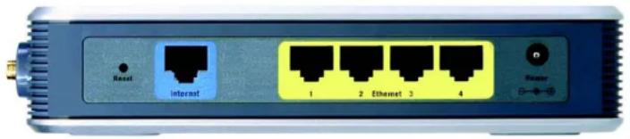
text_image
Reset Interact 1 2 Ethernet 3 4 PowerFigure 3-1: The Router's Back Panel
Reset Button There are two ways to reset the Router's factory defaults. Either press the Reset Button, for approximately five seconds, or restore the defaults from the Administration tab - Factory Defaults in the Router's Web-based Utility.
Internet The Internet port is where you will connect your broadband Internet connection.
Ethernet 1, 2, 3, 4 These ports (1, 2, 3, 4) connect the Router to your networked PCs and other Ethernet network devices.
Power The Power port is where you will connect the power adapter.

IMPORTANT: Resetting the Router will erase all of your settings (Internet connection, wireless security, and other settings) and replace them with the factory defaults. Do not reset the Router if you want to retain these settings.
Chapter 3: Getting to Know the Wireless-G Broadband Router with RangeBooster The Back Panel
Wireless-G Broadband Router with RangeBooster
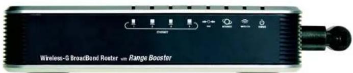
The Front Panel
The Router's LEDs are located on the front panel.
text_image
Wireless-G BroadBond Roster with Range BoosterFigure 3-2: The Router's Front Panel
| Ethernet 1, 2, 3, 4 | Green. These numbered LEDs, corresponding with the numbered ports on the Router's back panel, serve two purposes. If the LED is continuously lit, the Router is successfully connected to a device through that port. A flashing LED indicates network activity over that port. |
| DMZ | Green. The DMZ LED indicates when the DMZ function is being used. This LED will remain lit as long as DMZ is enabled. |
| Internet | Green. The Internet LED lights up when there is a connection made through the Internet port. |
| Wireless | Green. The Wireless LED lights up whenever there is a successful wireless connection. If the LED is flashing, the Router is actively sending or receiving data over the network. |
| Power | Green. The Power LED lights up and will stay on while the Router is powered on. |
Chapter 3: Getting to Know the Wireless-G Broadband Router with RangeBooster The Front Panel
Wireless-G Broadband Router with RangeBooster

text_image
Collection of symbolic and stylized icons including asterisks, squares, and triangles with standard text alignmentHardware Installation for Connection to Your Broadband Modem
- Power down your network devices.
- Locate an optimum location for the Router. The best place for the Router is usually at the center of your wireless network, with line of sight to all of your mobile stations.
- Fix the direction of the antennas. Place the antennas at a 45 degree angle for best performance.
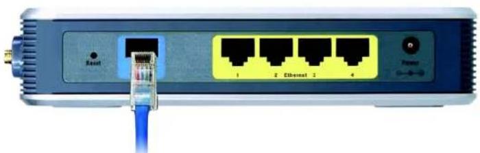
- Connect a standard Ethernet network cable to the Router's Internet port. Then, connect the other end of the Ethernet cable to your cable or DSL broadband modem.
natural_image
Front view of a network switch with Ethernet port and power outlet (no text or symbols visible)Figure 4-1: Connecting Your Internet Connection
Chapter 4: Connecting the Wireless-G Broadband Router with RangeBooster Hardware Installation for Connection to Your Broadband Modem
Wireless-G Broadband Router with RangeBooster
- Connect your network PCs or Ethernet devices to the Router's numbered ports using standard Ethernet network cabling.

natural_image
Front view of a network switch device showing ports and a blue cable (no readable text or symbols)Figure 4-2: Connecting Your Network Devices
- Connect the AC power adapter to the Router's Power port and the other end into an electrical outlet. Only use the power adapter supplied with the Router. Use of a different adapter may result in product damage.

natural_image
Front view of a network switch with ports labeled 1, 2, 3, and 4, connected via a cable (no readable text beyond port labels)Figure 4-3: Connecting the Power

IMPORTANT: Make sure you use the power adapter that is supplied with the Router. Use of a different power adapter could damage the Router.
Now that the hardware installation is complete, proceed to "Chapter 5: Setting up the Wireless-G Broadband Router with RangeBooster," for directions on how to configure the Router.
Chapter 4: Connecting the Wireless-G Broadband Router with RangeBooster Hardware Installation for Connection to Your Broadband Modem
Wireless-G Broadband Router with RangeBooster

text_image
Collection of various geometric symbols and markings, including asterisks, squares, and triangles with standard line styles.Overview

NOTE: For first-time installation, Linksys recommends using the Setup Wizard on the Setup CD-ROM. If you want to configure advanced settings, use this chapter to learn about the Web-based Utility.
Linksys recommends using the Setup CD-ROM for first-time installation of the Router. If you do not wish to run the Setup Wizard on the Setup CD-ROM, then you can use the Web-based Utility to configure the Router. For advanced users, you may configure the Router's advanced settings through the Web-based Utility.
This chapter will describe each web page in the Utility and each page's key functions. The utility can be accessed via your web browser through use of a computer connected to the Router. For a basic network setup, most users will use these two screens of the Utility:
- Basic Setup. On the Basic Setup screen, enter the settings provided by your ISP.
- Management. Click the Administration tab and then the Management tab. The Router's default password is admin. To secure the Router, change the Password from its default.
There are seven main tabs: Setup, Wireless, Security, Access Restrictions, Applications & Gaming, Administration, and Status. Additional tabs will be available after you click one of the main tabs.
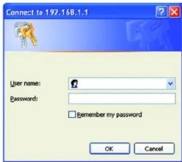
To access the Web-based Utility, launch Internet Explorer or Netscape Navigator, and enter the Router's default IP address, 192.168.1.1, in the Address field. Then press Enter.
A password request page, shown in Figure 6-1 will appear. (Non-Windows XP users will see a similar screen.) Leave the User Name field blank. The first time you open the Web-based Utility, use the default password admin. (You can set a new password from the Administration tab's Management screen.) Then click the OK button.

HAVE YOU: Enabled TCP/IP on your PCs? PCs communicate over the network with this protocol. Refer to "Appendix D: Windows Help" for more information on TCP/IP.
text_image
Connect to 192.168.1.1 User name: Password: Remember my password OK CancelFigure 5-1: Password Screen
Wireless-G Broadband Router with RangeBooster
The Setup Tab - Basic Setup
The first screen that appears displays the Setup tab. This allows you to change the Router's general settings. Change these settings as described here and click the Save Settings button to apply your changes or Cancel Changes to cancel your changes.
Internet Setup
The Internet Setup section configures the Router to your Internet connection. Most of this information can be obtained through your ISP.
Internet Connection Type
Choose the type of Internet connection your ISP provides from the drop-down menu.
- DHCP. By default, the Router's Internet Connection Type is set to Automatic Configuration - DHCP, which should be kept only if your ISP supports DHCP or you are connecting through a dynamic IP address.
- Static IP. If you are required to use a permanent IP address to connect to the Internet, select Static IP.
Internet IP Address. This is the Router's IP address, when seen from the Internet. Your ISP will provide you with the IP Address you need to specify here.
Subnet Mask. This is the Router's Subnet Mask, as seen by users on the Internet (including your ISP). Your ISP will provide you with the Subnet Mask.
Default Gateway. Your ISP will provide you with the Gateway Address, which is the ISP server's IP address.
DNS. Your ISP will provide you with at least one DNS (Domain Name System) Server IP Address.

text_image
LINKSYS® A Solution for Our System, Inc. SET PLUG Setup Status: Windows Binary Microsoft Macintosh Protocol & Control Administration Status System Setup DHCP MPC Address: C# Advanced Setting Network Settings Internal Connection Type Optional Settings (Required by wireless Preferred Service Providers) Automatic Configuration - DHCP Host name: Disease Name: MHz Auto Size Network Settings Model IP IP Address: 162 165 1 Subnet Mask: 266.285.285.0 DHCP Server: Disabled Disabled Data DHCP Start IP Address: 162.165.3 169 Maximum Number of Users: IC IP Address Range: 162.1691.102 - 169 Client License Time: 9 minutes (3 times one day) State: SMS 1: 0 0 0 0 State: SMS 2: 0 0 0 0 State: SMS 3: 0 0 0 0 FNG: 0 0 0 0 0 Time Settings Time Name: QMT-08/02:Public Test (USA) & Canada: Automatically adjust clock for daylight viewing charges. Save Settings Cancel Changes Help.Figure 5-2: Setup Tab - Basic Setup

Figure 5-3: DHCP Connection Type

text_image
Internet Connection Type Static IP Internet IP Address: 0, 0, 0, 0 Subnet Music: 0, 0, 0, 0 Default Gateway: 0, 0, 0, 0 DNS 1: 0, 0, 0, 0 DNS 2: 0, 0, 0, 0 DNS 3: 0, 0, 0, 0Figure 5-4: Static IP Connection Type
Static IP address: a fixed address assigned to a computer or device connected to a network.
Wireless-G Broadband Router with RangeBooster
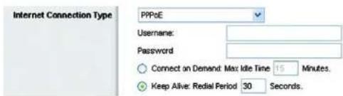
- PPPoE. Some DSL-based ISPs use PPPoE (Point-to-Point Protocol over Ethernet) to establish Internet connections. If you are connected to the Internet through a DSL line, check with your ISP to see if they use PPPoE. If they do, you will have to enable PPPoE.
User Name and Password. Enter the User Name and Password provided by your ISP.
Connect on Demand: Max Idle Time. You can configure the Router to cut the Internet connection after it has been inactive for a specified period of time (Max Idle Time). If your Internet connection has been terminated due to inactivity, Connect on Demand enables the Router to automatically re-establish your connection as soon as you attempt to access the Internet again. If you wish to activate Connect on Demand, click the radio button. In the Max Idle Time field, enter the number of minutes you want to have elapsed before your Internet connection terminates.
Keep Alive Option: Redial Period. If you select this option, the Router will periodically check your Internet connection. If you are disconnected, then the Router will automatically re-establish your connection. To use this option, click the radio button next to Keep Alive. In the Redial Period field, you specify how often you want the Router to check the Internet connection. The default Redial Period is 30 seconds.
- PPTP. Point-to-Point Tunneling Protocol (PPTP) is a service that applies to connections in Europe only.
Server IP Address. This is the Router's IP address, as seen from the Internet. Your ISP will provide you with the IP Address you need to specify here.
Subnet Mask. This is the Router's Subnet Mask, as seen by users on the Internet (including your ISP). Your ISP will provide you with the Subnet Mask.
Default Gateway. Your ISP will provide you with the Gateway Address.
User Name and Password. Enter the User Name and Password provided by your ISP.
Connect on Demand: Max Idle Time. You can configure the Router to cut the Internet connection after it has been inactive for a specified period of time (Max Idle Time). If your Internet connection has been terminated due to inactivity, Connect on Demand enables the Router to automatically re-establish your connection as soon as you attempt to access the Internet again. If you wish to activate Connect on Demand, click the radio button. In the Max Idle Time field, enter the number of minutes you want to have elapsed before your Internet connection terminates.
Keep Alive Option: Redial Period. If you select this option, the Router will periodically check your Internet connection. If you are disconnected, then the Router will automatically re-establish your connection. To use this option, click the radio button next to Keep Alive. In the Redial Period field, you specify how often you want the Router to check the Internet connection. The default Redial Period is 30 seconds.
text_image
Internet Connection Type PPPoE Username: Password Connect on Demand: Max: Idle Time 15 Minutes. Keep Alive: Redial Period 30 Seconds.Figure 5-5: PPPoE Connection Type

text_image
Internet Connection Type PPTP Server IP Address: 0 0 0 0 Subnet Mask: 0 0 0 0 Default Gateway: 0 0 0 0 Username: Password: Connect on Demand: Max Idle Time 15 Minutes. Keep Alive: Redial Period 30 Seconds.Figure 5-6: PPTP Connection Type
Wireless-G Broadband Router with RangeBooster
- HeartBeat Signal. HeartBeat Signal (HBS) is a service that applies to connections in Australia only. If your ISP is Telstra, then select HeartBeat Signal.
User Name and Password. Enter the User Name and Password provided by your ISP.
Server IP Address. This is the IP address that the Router has, when seen from the Internet. Your ISP will provide you with the IP Address you need to specify here.

text_image
Internet Connection Type Heart Best Signal Server IP Address: 0 .0 .0 .0 Username: Password:Figure 5-7: HeartBeat Signal Connection Type
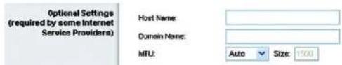
Optional Settings
Some of these settings may be required by your ISP. Verify with your ISP before making any changes.
Host Name. In this field, you can type a name of up to 39 characters to represent the Router.
Host Name/Domain Name. These fields allow you to supply a host and domain name for the Router. Some ISPs, usually cable ISPs, require these names as identification. You may have to check with your ISP to see if your broadband Internet service has been configured with a host and domain name. In most cases, leaving these fields blank will work.
MTU. MTU is the Maximum Transmission Unit. It specifies the largest packet size permitted for Internet transmission. The default setting, Manual, allows you to enter the largest packet size that will be transmitted. You should leave this value in the 1200 to 1500 range. To have the Router select the best MTU for your Internet connection, select Auto.
text_image
Optional Settings (required by some Internet Service Providers) Host Name: Domain Name: MTU: Auto Size: 1500Figure 5-8: Optional Settings
Network Setup
The Network Setup section changes the settings on the network connected to the Router's Ethernet ports. Wireless Setup is performed through the Wireless tab.
Router IP
This presents both the Router's IP Address and Subnet Mask as seen by your network.

Figure 5-9: Router IP
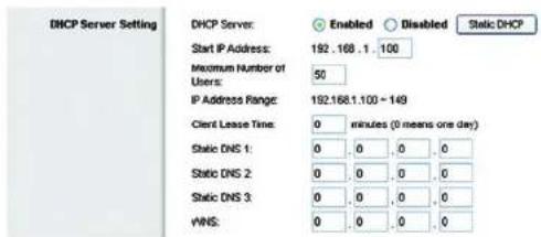
DHCP Server Settings
The settings allow you to configure the Router's Dynamic Host Configuration Protocol (DHCP) server function. The Router can be used as a DHCP server for your network. A DHCP server automatically assigns an IP address to each computer on your network. If you choose to enable the Router's DHCP server option, you must configure all of your network PCs to connect to a DHCP server (the Router), and make sure there is no other DHCP server on your network.
Chapter 6: Configuring the Wireless-G Broadband Router with RangeBooster The Setup Tab - Basic Setup
Wireless-G Broadband Router with RangeBooster
DHCP Server. DHCP is enabled by factory default. If you already have a DHCP server on your network, or you don't want a DHCP server, then click the Disable radio button (no other DHCP features will be available).
Start IP Address. Enter a value for the DHCP server to start with when issuing IP addresses. Because the Router's default IP address is 192.168.1.1, the Starting IP Address must be 192.168.1.2 or greater, but smaller than 192.168.1.253. The default Starting IP Address is 192.168.1.100.
Maximum Number of DHCP Users. Enter the maximum number of PCs that you want the DHCP server to assign IP addresses to. This number cannot be greater than 253. The default is 50.
Client Lease Time. The Client Lease Time is the amount of time a network user will be allowed connection to the Router with their current dynamic IP address. Enter the amount of time, in minutes, that the user will be "leased" this dynamic IP address. After the time is up, the user will be automatically assigned a new dynamic IP address. The default is 0 minutes, which means one day.
Static DNS (1-3). The Domain Name System (DNS) is how the Internet translates domain or website names into Internet addresses or URLs. Your ISP will provide you with at least one DNS Server IP Address. If you wish to use another, type that IP Address in one of these fields. You can type up to three DNS Server IP Addresses here. The Router will use these for quicker access to functioning DNS servers.
WINS. The Windows Internet Naming Service (WINS) manages each PC's interaction with the Internet. If you use a WINS server, enter that server's IP Address here. Otherwise, leave this blank.
Static DHCP Client button. The Static DHCP Client button is used if you want to assign a fixed IP address to a MAC address. Enter the static local IP address in the Assign this IP field, and enter the MAC address of the PC in the To this MAC field. Then click the Enabled checkbox. When you have finished your entries, click the Save Settings button to save your changes. Click the Cancel Changes button to cancel your changes. To exit this screen, click the Close button.
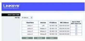
DHCP Client Table button. On the DHCP Client Table screen, you will see a list of DHCP clients with the following information: Client Name, Interface, IP Address, and MAC Address. From the Sort by drop-down menu, you can sort the table by Client Name, Interface, IP Address, or MAC Address. If you want to add any of the DHCP clients to the Static DHCP Client List, then click the Save to Static DHCP Client List checkbox and then click the Save Settings button. Click the Cancel Changes button to cancel your changes. To view the most up-to-date information, click the Refresh button. To exit this screen, click the Close button.
Time Setting
Change the time zone in which your network functions from this pull-down menu. (You can even automatically adjust for daylight savings time.)
text_image
DHCP Server Setting DHCP Server: Enabled Disabled Static DHCP Start IP Address: 192.168.1.100 Maximum Number of Users: 50 IP Address Range: 192.168.1.100 ~ 149 Client Lease Time: 0 minutes (0 means one day) Static DNS 1: 0, 0, 0, 0 Static DNS 2: 0, 0, 0, 0 Static DNS 3: 0, 0, 0, 0 WNS: 0, 0, 0, 0Figure 5-10: DHCP Server Settings

text_image
LINKSYS A Series of DCP Systems, Inc. Satic DISCP Class List DSCP Class Table Average Tax P I/O bus MAC I/INT 102 100 0 0 102 100 0 0 102 100 0 0 102 100 0 0 102 100 0 0 102 100 0 0 102 100 0 0 102 100 0 0 102 100 0 0 104 100 0 0 104 100 0 0 104 100 0 0 104 100 0 0 104 100 0 0 104 100 0 0 104 100 0 0 104 100 0 0 104 105 0 0 104 105 0 0 104 105 0 0 104 105 0 0 104 105 0 0 104 105 0 0 104 105 0 0 104 105 0 0 104 105 0 1 Total Settings Closed Changes UnitsFigure 5-11: Static DHCP Client List
text_image
LINKSYS Client Name: Client Server Send to: Cloud Name Interface IP Address MAC Address Save to static MCC/Server 1 IP: 162 000 1.58 100 000 30 32.00 □ MCCs1 VMW-A 162 000 1.59 100 000 30 32.00 □ MCCs2 VMW-B 162 000 1.59 100 000 30 32.00 □ MCCs3 VMW-C 162 000 1.59 100 000 30 32.00 □ MCCs4 VMW-D 162 000 1.59 100 000 30 32.00 □ ADD BORDER BASEFigure 5-12: DHCP Client Table

Figure 5-13: Time Setting
Wireless-G Broadband Router with RangeBooster
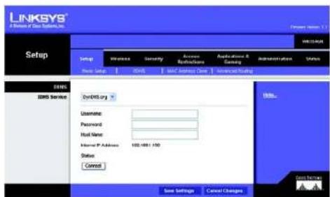
The Setup Tab - DDNS
The Router offers a Dynamic Domain Name System (DDNS) feature. DDNS lets you assign a fixed host and domain name to a dynamic Internet IP address. It is useful when you are hosting your own website, FTP server, or other server behind the Router. Before you can use this feature, you need to sign up for DDNS service with a DDNS service provider, www.dyndns.org or www.TZO.com.
DDNS.com
DDNS Service. From this pull-down menu, enter the DDNS service with which you have membership.
User Name. Enter the User Name for your DDNS account
Password. Enter the Password for your DDNS account.
Host Name. The is the DDNS URL assigned by the DDNS service.
Internet IP Address. This is the Router's current IP Address as seen on the Internet.
Status. This displays the status of the DDNS connection.
Connect button. Click this button to connect to the service.
Change these settings as described here and click the Save Settings button to apply your changes or Cancel Changes to cancel your changes.
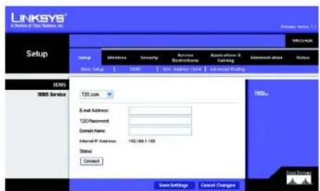
TZO.com
Email Address. Enter the Email Address of the service you set up with TZO.
TZ0 Password. Enter the TZ0 Password Key of the service you set up with TZ0.
Domain Name. Enter the Domain Name of the service you set up with TZO.
Internet IP Address. The Router's current Internet IP Address is displayed here. Because it is dynamic, this will change.
Status. This displays the status of the DDNS connection.
Connect button. Click this button to connect to the service.
text_image
LINKSYS A Division of Our Security, Inc. Setup Settings Wireless Security Access Authentication Applications Services DNS DNS Service DNS/DNS org Username: Password: Host Name: Internet P Address: 102-4861 150 Status Connect Save Settings Cancel Changes Bills... Gross ServicesFigure 5-14: Setup Tab - DDNS.com
text_image
LINKSYS A Division of Our Service, Inc. Setup LinkSYS 9.1.1 Setup Windows Security Access Accessories Accession & Carling Accession status Status Data Setup Web Net Adder/View Services Pricing EMS EMS Service T20.com Email Address: T20 Password: Domain Name: Internet P Address: 182/69.1.100 Status: Connect Save Settings Cancel Changes Send to: Save Settings Cancel ChangesFigure 5-15: Setup Tab - TZO.com
Chapter 6: Configuring the Wireless-G Broadband Router with RangeBooster The Setup Tab - DDNS
Wireless-G Broadband Router with RangeBooster
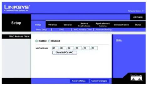
The Setup Tab - MAC Address Clone
A MAC address is a 12-digit code assigned to a unique piece of hardware for identification. Some ISPs will require you to register a MAC address in order to access the Internet. If you do not wish to re-register the MAC address with your ISP, you may assign the MAC address you have currently registered with your ISP to the Router with the MAC Address Clone feature.
Enable/Disable. To have the MAC Address cloned, click the radio button beside Enable.
MAC Address. Enter the MAC Address registered with your ISP here.
Clone My PC's MAC. Clicking this button will clone the MAC address.
Change these settings as described here and click the Save Settings button to apply your changes or Cancel Changes to cancel your changes.
text_image
LINKSYS® A Division of Data System, Inc. Setup Setup Wireless Security Access Access Breakthrough Applications & Marketing Administration Shares Dec. 1 Sep 2005 MAC Address Close Advanced Packing MAC Address Close Enabled Enabled MAC Address 00 00 00 00 00 00 Close by PC's MAC Save Settings Cancel Changes ENDs Save SettingsFigure 5-16: Setup Tab - MAC Address Clone
Chapter 6: Configuring the Wireless-G Broadband Router with RangeBooster The Setup Tab - MAC Address Clone
Wireless-G Broadband Router with RangeBooster
The Setup Tab - Advanced Routing
This tab is used to set up the Router's advanced functions. Operating Mode allows you to select the type(s) of advanced functions you use. Dynamic Routing will automatically adjust how packets travel on your network. Static Routing sets up a fixed route to another network destination.
NAT. If this Router is hosting your network's connection to the Internet, select Enable. If another Router exists on your network, select Disable. When Router is chosen, Dynamic Routing will be enabled.
Dynamic Routing (RIP). This feature enables the Router to automatically adjust to physical changes in the network's layout and exchange routing tables with the other router(s). The Router determines the network packets' route based on the fewest number of hops between the source and the destination. When setting this up, remember that the settings on the receiving and transmitting side must be the same.
Static Routing. To set up a static route between the Router and another network, select a number from the Route Entries drop-down list. (A static route is a pre-determined pathway that network information must travel to reach a specific host or network.) Enter the information described below to set up a new static route. (Click the Delete This Entry button to delete a static route.)
Enter Route Name. Enter a name for the Route here, using a maximum of 25 alphanumeric characters.
Destination LAN IP: The Destination LAN IP is the address of the remote network or host to which you want to assign a static route.
Subnet Mask. The Subnet Mask determines which portion of a Destination LAN IP address is the network portion, and which portion is the host portion.
Gateway This is the IP address of the gateway device that allows for contact between the Router and the remote network or host.
Interface This interface tells you whether the Destination IP Address is on the LAN & Wireless (Ethernet and wireless networks), the Internet (WAN), or Loopback (a dummy network in which one PC acts like a network—necessary for certain software programs).
Click the Show Routing Tablebutton to view the Static Routes you've already set up. Click the Refresh button to refresh the screen. Click the Close button to close the window and return to the Advanced Routing screen.
Change these settings as described here and click the Save Settings button to apply your changes or Cancel Changes to cancel your changes.

text_image
LINKSYS A Division of Data Systems, Inc. Setup WNT1004X Setup Inference Security Access Accessories Applications & Licensing Administration Status Details Select MAT Address (Temp) Advanced Routing Advanced Routing WAT Involved Enabled Dynamic Routing (WP) Involved Enabled Static Routing Route Entries Delete This Entry Enter Route Name: Destination LOOP: 0 0 0 0 Subset List: 0 0 0 0 Gateway: 0 0 0 0 Interface: LAB & Wireless Show Routing Table Save Settings Cancel ChangesFigure 5-17: Setup Tab - Advanced Routing

text_image
LINKSYS® A Division of Data Systems, Inc. Routing Table Destination LAH IP Subset Mask Gateway Interface 10.10 10.100 255.255.255.0 1010.10.1 Internet (WIN) 192.188.1.100 255.255.255.0 192.188.1.1 LAN & Wireless Refresh CloseFigure 5-18: Setup Tab - Routing Table
Wireless-G Broadband Router with RangeBooster
The Wireless Tab - Basic Wireless Settings
The basic settings for wireless networking are set on this screen.
Wireless. Select Enabled to enable wireless capabilities or Disabled to disable wireless.
Network Mode. From this drop-down menu, you can select the wireless standards running on your network. If you have both 802.11g and 802.11b devices in your network, keep the default setting, Mixed. If you have only 802.11g devices, select Wireless G-Only. If you have only 802.11b devices, select Wireless B-Only. If you do not have any 802.11g and 802.11b devices in your network, select Disable.
Wireless Network Name (SSID). The SSID is the network name shared among all devices in a wireless network. The SSID must be identical for all devices in the wireless network. It is case-sensitive and must not exceed 32 characters (use any of the characters on the keyboard). Make sure this setting is the same for all devices in your wireless network. For added security, you should change the default SSID (linksys) to a unique name.
Channel. Select the appropriate channel from the list provided to correspond with your network settings. All devices in your wireless network must be broadcast on the same channel in order to function correctly.
SSID Broadcast. When wireless clients survey the local area for wireless networks to associate with, they will detect the SSID broadcast by the Router. To broadcast the Router's SSID, keep the default setting, Enable. If you do not want to broadcast the Router's SSID, then select Disable.
Change these settings as described here and click the Save Settings button to apply your changes or Cancel Changes to cancel your changes.

text_image
LINKSYS® A Division of Data Systems, Inc. Wireless Setup Wireless Security Access Receivations Applications & Settings Administration Status New Server Settings Wireless Security Wireless MAC Filter Advanced/Wireless Settings Basic Wireless Settings Wireless Enabled Disabled Network Mode: Music Network Name (SSD) Intrips Channel 6.2.03GHz SSD Broadcast Enabled Disabled Mills... Save Settings Cancel Changes Data ServersFigure 5-19: Wireless Tab - Basic Wireless Settings
Wireless-G Broadband Router with RangeBooster
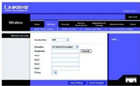
The Wireless Tab - Wireless Security
The Wireless Security settings configure the security of your wireless network. There are four wireless security mode options supported by the Router: WEP, WPA Personal, PSK2, PSK2-Mixed, WPA-Enterprise, PSK2 + RADIUS, and RADIUS. (WEP stands for Wired Equivalent Privacy, and WPA stands for Wi-Fi Protected Access. WPA is a stronger security method than WEP. PSK2 stands for Pre-shared Key 2, and Is stronger than WPA-Personal. RADIUS stands for Remote Authentication Dial-In User Service.) These seven are briefly discussed here.
WEP. WEP is a basic encryption method, which is not as secure as WPA Personal. To use WEP, select a level of WEP encryption, 40/64 bits (10 hex digits) or 104/128 bits (26 hex digits). Then either generate a WEP key using the Passphrase or enter the WEP key manually and select a TX (Transmit) Key (choose which Key to use).
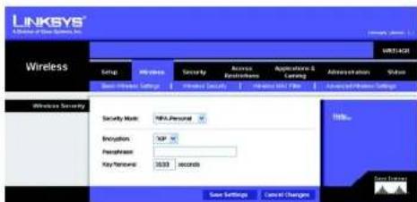
WPA-Personal. WPA gives you two encryption methods, TKIP and AES, with dynamic encryption keys. Select the type of encryption, TKIP or AES. Enter a passphrase (pre-shared key) of 8-63 characters. Then enter a Key Renewal period, which instructs the Router how often it should change the encryption keys.

IMPORTANT: If you are using WEP encryption, always remember that each device in your wireless network MUST use the same WEP encryption method and encryption key, or else your wireless network will not function properly.
text_image
LINKSYS A Series of Data Systems, Inc. Wireless Service Wireless Security Access Enabling Applications & Learning Administration Status Next Wireless Settings Wireless Security Wireless Security Security Mode: HSP Evolution: 45/54 M (10 Hz MHz) Presence: General Key-1: Key-2: Key-3: Key-4: TX Key: OK... Data Security Save Settings Cancel ChangesFigure 5-20: Wireless Tab - Wireless Security (WEP)
text_image
LINKSYS A Division of Blue Systems, Inc. Wireless Setup Wireless Security Access Security & Setting Access Security Access Security Access Security Settings Wireless Security Security Mask: HNS-Personal Encryption: XIP Personalset: Key-Termostat: 3633 seconds Save Settings Cancel Changes Winls... Data SettingsFigure 5-21: Wireless Tab - Wireless Security (WPA-Personal)

IMPORTANT: If you are using WPA Personal, always remember that each device in your wireless network MUST use the same WPA Personal method and passphrase, or else the network will not function properly.
Wireless-G Broadband Router with RangeBooster
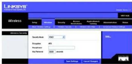
PSK2. PSK2 is stronger than WPA Personal and gives you one encryption method, AES, with dynamic encryption keys. Enter a Passphrase of 8-63 characters. Then enter a Key Renewal period, which instructs the Router how often it should change the encryption keys.
text_image
LINKSYS Access of Cloud System, Inc. Wireless Setup Wireless Security Access Wireless Application & Catalog Administration Share New Windows Settings Wireless Security Wireless Net Filter Americal/Power Settings Wireless Security Security Mask: 1503 Encryption: 465 Peripherals: Key-Termostat: 2600 seconds OK... Save Settings Cancel ChangesFigure 5-22: Wireless Tab - Wireless Security (PSK2)
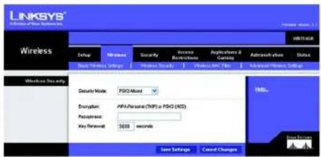
PSK2-Mixed. PSK2-Mixed gives you either WPA-Personal (TKIP) or PSK2 (AES) encryption. Enter a Passphrase of 8-63 characters. Then enter a Key Renewal period, which instructs the Router how often it should change the encryption keys.
text_image
LINKSYS A Software Of Blue Systems Inc. Wireless Setup Wireless Security Access Networks Applications & Controls Administration Status Show Settings Show Security Show Data Filter Advanced Wireless Settings Wireless Security Security Note: PSX2-Mixed Encryption: APPA-Perseate (TMP) - PSX2 (MOS) Passives: Key Renewal: 3600 seconds Save Settings Cancel Changes Help... Data SecurityFigure 5-23: Wireless Tab - Wireless Security (PSK2-Mixed)
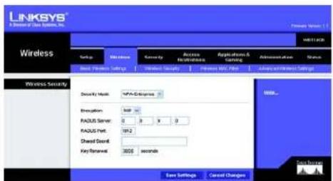
WPA Enterprise. This option features WPA used in coordination with a RADIUS server. (This should only be used when a RADIUS server is connected to the Router.) First, select the type of WPA encryption you want to use, TKIP or AES. Enter the RADIUS server's IP Address and port number, along with a shared secret (authentication key) between the Router and the server. Last, enter a Key Renewal Timeout, which instructs the Router how often it should change the encryption keys.
text_image
LINKSYS A Division of Data Systems, Inc. Wireless Wireless Security Security Mask: NPS-0109999 Description: 800 PAGUS Server: 0 0 0 0 PAGUS Port: 1912 Shared Devel: Key Forward: 3600 seconds Save Settings Cancel Changes Browse... Save PresetsFigure 5-24: Wireless Tab - Wireless Security (WPA Enterprise)
Chapter 6: Configuring the Wireless-G Broadband Router with RangeBooster The Wireless Tab - Wireless Security
Wireless-G Broadband Router with RangeBooster
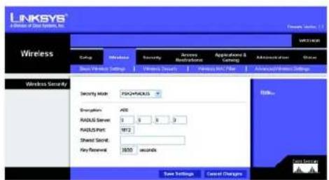
PSK2 + RADIUS. This option features a PSK2 used in coordination with a RADIUS server. (This should only be used when a RADIUS server is connected to the Router.) AES is the type of encryption method used. Enter the RADIUS server's IP address and port number, along with the shared secret (authentication key) shared by the Router and the server. Last, enter the Key Renewal period, which instructs the Router how often it should change the encryption keys.
text_image
LINKSYS A Release of Data Network, Inc. Wireless Wireless Security Security Code: PSCHIKUS Energy RADIUS Secret: 0 0 0 RADIUS Port: 1812 Sheet Secret: Key Renewal: 3650 seconds Save Settings Cancel Changes Data SecurityFigure 5-25: Wireless Tab - Wireless Security (PSK2 + RADIUS)
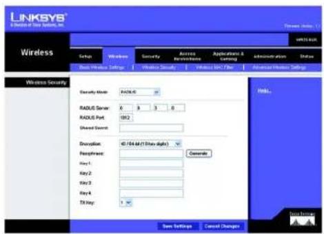
RADIUS. This option features WEP used in coordination with a RADIUS server. (This should only be used when a RADIUS server is connected to the Router.) First, enter the RADIUS server's IP Address and port number, along with a shared secret (authentic key) shared between the Router and the server. Then, select a level of WEP encryption, 40/64 bits 10 hex digits or 104/128 bits 26 hex digits and either generate a WEP key using the Passphrase or enter the WEP key manually, and lastly, select a Default Transmit Key (choose which Key to use).
text_image
LINKSYS® & Deviation of Data Security, Inc. Wireless Setup Windows Security Access Accession Applications & Landing Administration Status Real Wireless Settings Wireless Security Security Mode: RADIUS: 0.5 Radius Server: 0.5 Radius Port: 1912 Shared Service: Description: 40 / 64 bit (1 Show digits) Peripherals: Generate Key1: Key2: Key3: Key4: TX Key: 1 Save Settings Cancel Changes Help... Data PrivacyFigure 5-26: Wireless Tab - Wireless Security (RADIUS)
Change these settings as described here and click the Save Settings button to apply your changes or Cancel Changes to cancel your changes.
Wireless-G Broadband Router with RangeBooster
The Wireless Tab - Wireless MAC Filter
Wireless access can be filtered by using the MAC addresses of the wireless devices transmitting within your network's radius.
Wireless MAC Filter
To filter wireless users by MAC Address, either permitting or blocking access, click Enabled. If you do not wish to filter users by MAC Address, select Disabled.
Access Restriction
Prevent PCs listed below from accessing the wireless network. Clicking this button will block wireless access by MAC Address.
Permit PCs listed below to access the wireless network. Clicking this button will allow wireless access by MAC Address.
MAC Address Filter List
You can manually enter a MAC address to filter or you can select one from the Wireless Client List.
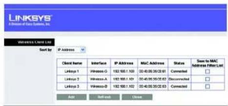
Wireless Client List. Click the Wireless Client MAC List button to display a list of wireless network users. From the To Sort by drop-down menu, you can sort the table by Client Name, IP Address, MAC Address, Interface, or Client Name. To add a client's MAC Address to your MAC Address Filter list, click the Save to MAC Address Filter List checkbox and click the Add button. To view the most up-to-date information, click the Refresh button. To exit this screen, click the Close button.
Change these settings as described here and click the Save Settings button to apply your changes or Cancel Changes to cancel your changes.

text_image
LINKSYS A Division of Class Systems, Inc. Wireless Status Network Security Access Accessories Applications & Testing Application Status Back Power Settings Network Security Service Web File Internet Settings Wireless MAC Filter Installed Disabled Access Read/Info Powered PCs based before accessing the wireless network. Powered PCs based before to access the wireless network. MAC Address Filter List Wireless Client List MAC01 09:00:00:00:00 MAC 00 00:00:00:00:00 MAC02 09:00:00:00:00 MAC 13 00:00:00:00:00 MAC03 09:00:00:00:00 MAC 11 00:00:00:00:00 MAC04 09:00:00:00:00 MAC 13 00:00:00:00:00 MAC05 09:00:00:00:00 MAC 13 00:00:00:00:00 MAC06 09:00:00:00:00 MAC 14 00:00:00:00:00 MAC07 09:00:00:00:00 MAC 15 00:00:00:00:00 MAC08 09:00:00:00:00 MAC 16 00:00:00:00:00 Save Settings Cancel ChangesFigure 5-27: Wireless Tab - Wireless MAC Filter
text_image
LINKSYS A Division of Data Systems, Inc. Wireless Client List Sort by IP Address Client Name Interface IP Address MAC Address Status Save to MAC Address Filter List Link1 Wireless-G 192.900.1.100 03:40:05:35:CE:61 Cancelled □ Link2 Wireless-A 192.900.1.100 03:40:05:35:CE:63 Disconnected □ Link3 Wireless-B 192.900.1.102 03:40:05:35:CE:63 Cancelled □ Add Refresh CloseFigure 5-28: Wireless Client List
Wireless-G Broadband Router with RangeBooster
The Wireless Tab - Advanced Wireless Settings
This tab is used to set up the Router's advanced wireless functions. These settings should only be adjusted by an expert administrator as incorrect settings can reduce wireless performance.
Advanced Wireless
Frame Burst Mode. Enabling this option should provide your network with greater performance, depending on the manufacturer of your wireless products. The default setting is Enabled.
AP Isolation. This isolates all wireless clients and wireless devices on your network from each other. Wireless devices will be able to communicate with the Router but not with each other. To use this function, click Enabled. AP Isolation is disabled by default.
Authentication Type. The default is set to Auto, which allows either Open System or Shared Key authentication to be used. With Open System authentication, the sender and the recipient do NOT use a WEP key for authentication. With Shared Key authentication, the sender and recipient use a WEP key for authentication.
Basic Rate. The Basic Rate setting is not actually one rate of transmission but a series of rates at which the Router can transmit. The Router will advertise its Basic Rate to the other wireless devices in your network, so they know which rates will be used. The Router will also advertise that it will automatically select the best rate for transmission. The default setting is Default, when the Router can transmit at all standard wireless rates (1-2Mbps, 5.5Mbps, 11Mbps, 18Mbps, and 24Mbps). Other options are 1-2Mbps, for use with older wireless technology, and All, when the Router can transmit at all wireless rates. The Basic Rate is not the actual rate of data transmission. If you want to specify the Router's rate of data transmission, configure the Transmission Rate setting.
Transmission Rate. The rate of data transmission should be set depending on the speed of your wireless network. You can select from a range of transmission speeds, or you can select Auto to have the Router automatically use the fastest possible data rate and enable the Auto-Fallback feature. Auto-Fallback will negotiate the best possible connection speed between the Router and a wireless client. The default setting is Auto.
Transmission Power. The greater the transmission power used, the larger the area a wireless network covers. To minimize the likelihood of eavesdropping by unauthorized wireless users, do not use more transmission power than necessary to cover the range needed by your wireless network. Try using the Router at different levels of transmission power, and determine how much power is needed to reach the wireless client, such as a PC or access point, that is farthest from the Router. Then select the appropriate level, Full, Half, Quarter, Eighth, or Min, from the drop-down menu. The default setting is Full.

text_image
LINKSYS A Division of Data Systems, Inc. Wireless Settings Access Accession Applications & Settings Administration Status Smart Wireless Settings Default Security Default User Advanced Wireless Settings Advanced Wireless Frame Bursts Mode Enabled Disabled (Default Enabled) AP Location Enabled Disabled (Default Enabled) Authentication Type: Auto Default Auto Basic Ratio: Default Default (Default) Transmission Rate: Auto Default Auto Transmission Power: Full Default Full CTS Protection Mode: Auto Default Auto Basic Interval: 103 (Default 100 Miscellaneous, Range 20 - 1000) COS Interval: 1 (Default 1, Range 1 - 200) Fragmentation Threshold: 298 (Default 256, Range 256 - 2548) RTC Threshold: 297 (Default 256, Range 256 - 2548) Save Settings Cancel Changes Data SettingsFigure 5-29: Wireless Tab - Advanced Wireless Settings
Wireless-G Broadband Router with RangeBooster
CTS Protection Mode. CTS (Clear-To-Send) Protection Mode's default setting is Auto. The Router will automatically use CTS Protection Mode when your Wireless-G products are experiencing severe problems and are not able to transmit to the Router in an environment with heavy 802.11b traffic. This function boosts the Router's ability to catch all Wireless-G transmissions but will severely decrease performance.
Beacon Interval. The Beacon Interval value indicates the frequency interval of the beacon. A beacon is a packet broadcast by the Router to synchronize the wireless network. The default value is 100.
DTIM Interval. This value indicates the interval of the Delivery Traffic Indication Message (DTIM). A DTIM field is a countdown field informing clients of the next window for listening to broadcast and multicast messages. When the Router has buffered broadcast or multicast messages for associated clients, it sends the next DTIM with a DTIM Interval value. Its clients hear the beacons and awaken to receive the broadcast and multicast messages. The default value is 1.
Fragmentation Threshold. This value specifies the maximum size for a packet before data is fragmented into multiple packets. If you experience a high packet error rate, you may slightly increase the Fragmentation Threshold. Setting the Fragmentation Threshold too low may result in poor network performance. Only minor reduction of the default value is recommended. The default value is 2346.
RTS Threshold. Should you encounter inconsistent data flow, only minor reduction of the default value, 2346, is recommended. If a network packet is smaller than the preset RTS threshold size, the RTS/CTS mechanism will not be enabled. The Router sends Request to Send (RTS) frames to a particular receiving station and negotiates the sending of a data frame. After receiving an RTS, the wireless station responds with a Clear to Send (CTS) frame to acknowledge the right to begin transmission. The default value is 2346.
Change these settings as described here and click the Save Settings button to apply your changes or Cancel Changes to cancel your changes.
Wireless-G Broadband Router with RangeBooster
The Security Tab - Firewall
The Firewall screen offers filters that block specific Internet data types and block anonymous Internet requests. Select the checkbox to enable a feature.
Firewall
SPI Firewall Protection. Enable this feature to employ Stateful Packet Inspection (SPI) for more detailed review of data packets entering your network environment.
Internet Filter
Filter Anonymous Internet Requests. When enabled, this feature keeps your network from being "pinged," or detected, by other Internet users. It also reinforces your network security by hiding your network ports. Both functions of this feature make it more difficult for outside users to work their way into your network. This feature is enabled by default. Select Disabled to allow anonymous Internet requests.
Filter Multicast. Multicasting allows for multiple transmissions to specific recipients at the same time. If multicasting is permitted, then the Router will allow IP multicast packets to be forwarded to the appropriate computers. Select Enabled to filter multicasting, or Disabled to disable this feature.
Filter Internet NAT Redirection. This feature uses port forwarding to block access to local servers from local networked computers. Select Enabled to filter Internet NAT redirection, or Disabled to disable this feature.
Filter IDENT (Port 113). This feature keeps port 113 from being scanned by devices outside of your local network. Select Enabled to filter port 113, or Disabled to disable this feature.
Web Filters
Proxy. Use of WAN proxy servers may compromise the Gateway's security. Denying Filter Proxy will disable access to any WAN proxy servers. To enable proxy filtering, click the checkbox.
Java. Java is a programming language for websites. If you deny Java, you run the risk of not having access to Internet sites created using this programming language. To enable Java filtering, click the checkbox.
ActiveX. ActiveX is a programming language for websites. If you deny ActiveX, you run the risk of not having access to Internet sites created using this programming language. To enable ActiveX filtering, click the checkbox.
Cookies. A cookie is data stored on your computer and used by Internet sites when you interact with them. To enable cookie filtering, click the checkbox.

text_image
LINKSYS® A Division of Data Systems, Inc. Security Setup Wireless Security Access Reconstitutes Applications & Gaming Administration Shares Frontset SP/Previal Protection Enabled Enabled Internet Filter Fiber Anonymous Internet Requests Fiber Multisheet Fiber Internet NAT Redirection Fiber ENTI (Port 113) Web Filter Ecovy Java ActiveX Cookies Save Settings Cancel ChangesFigure 5-30: Security Tab - Firewall
Wireless-G Broadband Router with RangeBooster
Change these settings as described here and click the Save Settings button to apply your changes or Cancel Changes to cancel your changes.
The Security Tab - VPN Passthrough
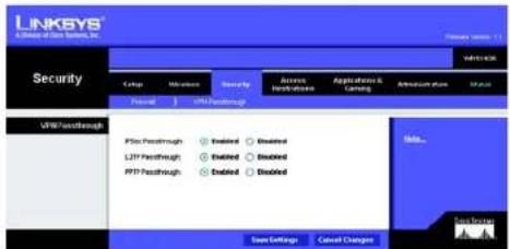
Use the settings on this tab to allow VPN tunnels using IPSec, L2TP, or PPTP protocols to pass through the Router's firewall.
IPSec Pass-through. Internet Protocol Security (IPSec) is a suite of protocols used to implement secure exchange of packets at the IP layer. To allow IPSec tunnels to pass through the Router, click Enable. IPSec Pass-Through is enabled by default.
L2TP Pass-through. Layer 2 Tunneling Protocol is the method used to enable Point-to-Point sessions via the Internet on the Layer 2 level. To allow L2TP tunnels to pass through the Router, click Enable. L2TP Pass-Through is enabled by default.
PPTP Pass-through. Point-to-Point Tunneling Protocol (PPTP) allows the Point-to-Point Protocol (PPP) to be tunneled through an IP network. To allow PPTP tunnels to pass through the Router, click Enable. PPTP Pass-Through is enabled by default.
Change these settings as described here and click the Save Settings button to apply your changes or Cancel Changes to cancel your changes.
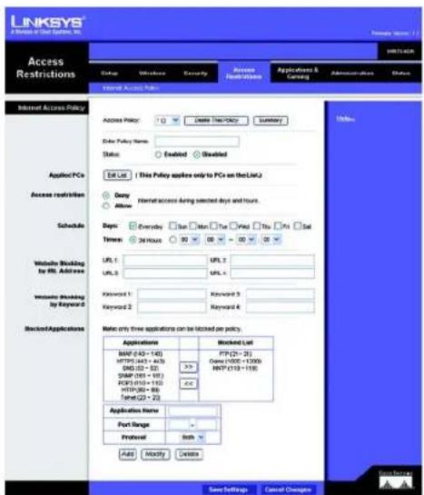
The Access Restrictions Tab - Internet Access Policy
The Internet Access Policy screen allows you to block or allow specific kinds of Internet usage and traffic, such as Internet access, designated services, and websites during specific days and times.
Internet Access Policy
Access Policy. Access can be managed by a policy. Use the settings on this screen to establish an access policy (after the Save Settings button is clicked). Selecting a policy from the drop-down menu will display that policy's settings. To delete a policy, select that policy's number and click the Delete This Policy button. To view all the policies, click the Summary button.
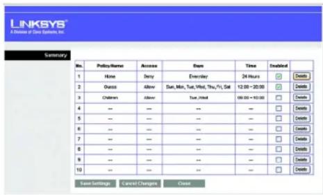
On the Summary screen, the policies are listed with the following information: No., Policy Name, Access, Days, Time, and status (Enabled) to view. To delete a policy, click its Delete button. Click the Save Settings button to save your changes, or click the Cancel Changes button to cancel your changes. To return to the Internet Access Policy tab, click the Close button.
text_image
LINKSYS A Series of Data Systems, Inc. Security Group Mission Security Server Application & Listing Accession plan Status VPS Touchthrough PTP Touchthrough LPTP Touchthrough PTP Touchthrough Enabled Enabled Enabled Enabled Enabled Save Settings Cancel Changes Send... Save Settings Cancel ChangesFigure 5-31: Security Tab - VPN Passthrough
text_image
LINKSYS® A Window of Our System, Inc. Access Restrictions HRT1-CAK Status Windows Security Access Restrictions Applications & Certifications Administrations Options Internet Access Policy Access Policy: Delete TCP/IPolicy Summary Enter Policy Name: Status: Enabled Enabled Edit List This Policy applies only to PCs on the LLaQ Duty Allow Internet access during selected days and hours. Days: Everyday Sun Mon Tue Print Thu Fri Sat Times: 24 Hours 90 00 30 00 Website Blocking for RIL Address URL 1: URL 2: URL 3: URL 4: Website Blocking by Keyword 5: Keyword 1: Keyword 2: Keyword 3: Keyword 4: Keyword 5: Keyword 6: Rejected Applications Note only three applications can be listed per policy. Applications MMP (443 - 140) HTTPS (443 - 443) DNS (22 - 22) SNMP (581 - 181) PCPS (510 - 150) HTTP (862 - 86) False (22 - 22) Application Name: Port Range: Protocol: Both: Auto Modify Cancel Save Settings Cancel Changes Help Save Settings Cancel ChangesFigure 5-32: Access Restrictions Tab - Internet Access Policy
Wireless-G Broadband Router with RangeBooster
To create an Internet Access policy:
- Select a number from the Access Policy drop-down menu.
- Enter a Policy Name in the field provided.
- To enable this policy, click Enabled.
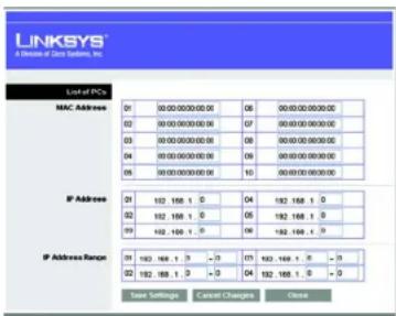
- Click the Edit List button to select which PCs will be affected by the policy. The Internet Access PCs List screen will appear. You can select a PC by MAC Address or IP Address. You can also enter a range of IP Addresses if you want this policy to affect a group of PCs. After making your changes, click the Save Settings button to apply your changes or Cancel Changes to cancel your changes. Then click the Close button.
- Click the appropriate option, Deny or Allow, depending on whether you want to block or allow Internet access for the PCs you listed on the List of PCs screen.
- Decide which days and what times you want this policy to be enforced. Select the individual days during which the policy will be in effect, or select Everyday. Then enter a range of hours and minutes during which the policy will be in effect, or select 24 Hours.
- You can also block access by URL address by entering it in the Website Blocking by URL Address field or by Keyword by entering it in the Website Blocking by Keyword field. Click the >> button to add a selection to the Blocked Applications list.
- You can filter access to various applications accessed over the Internet, such as FTP or telnet, by selecting up to three applications from the drop-down menus under Applications.
If the application you want to block is not listed or you want to edit an application's settings, then create a new one by entering an Application Name, Port Range, and Protocol. Then, click Add.
Click the Save Settings button to save the policy's settings. To cancel the policy's settings, click the Cancel Changes button.
text_image
LINKSYS 8 Division of Data System, Inc. Summary No. Policy Name Access Date Time Enabled 1 None Deny Everyday 24 Hours ✓ Delete 2 Status Allow Sun, Min, Sat, Wind, Thu, Fri, Sat 12:00 - 30:00 ✓ Delete 3 Children Allow Sun, Wind 00:00 - 50:00 ✓ Delete 4 -- -- -- -- ✓ Delete 5 -- -- -- -- ✓ Delete 6 -- -- -- -- -- ✓ Delete 7 -- -- -- -- -- ✓ Delete 8 -- -- -- -- -- ✓ Delete 9 -- -- -- -- -- ✓ Delete 10 -- -- -- -- -- ✓ Delete Save Settings Cancel Changes CloseFigure 5-33: Internet Policy Summary
text_image
LINKSYS A Release of Data Systems, Inc. List of PCs MAC Address 01 00:00:00:00:00 06 00:00:00:00:00 02 00:00:00:00:00 07 00:00:00:00:00 03 00:00:00:00:00 08 00:00:00:00:00 04 00:00:00:00:00 09 00:00:00:00:00 05 00:00:00:00:00 10 00:00:00:00:00 IP Address 21 192 168 1. 5 192 168 1. 5 22 192 168 1. 5 192 168 1. 5 23 192 168 1. 5 192 168 1. 5 IP Address Range: 31 192 168 1. 5 - 371 192 168 1. 5 - 3 32 192 168 1. 5 - 3 192 168 1. 5 - 3 Save Settings Cancel Changes CloseFigure 5-34: List of PCs
Wireless-G Broadband Router with RangeBooster
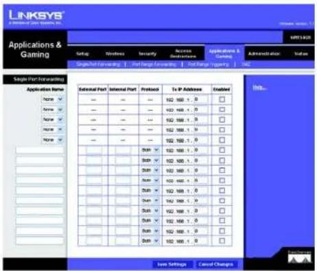
The Applications and Gaming Tab - Single Port Forwarding
Single Port Forwarding
The Single Port Forwarding screen provides options for customizing port services for common applications.
When users send this type of request to your network via the Internet, the Router will forward those requests to the appropriate computer. Any computer whose port is being forwarded should have its DHCP client function disabled and should have a new static IP address assigned to it because its IP address may change when using the DHCP function.
Select the pre-configured Application, or manually enter it in the field. Then, enter the External and Internal Port numbers in the fields. Select the type of protocol you wish to use for each application: TCP, UDP, or Both. Enter the IP Address in the field. Click Enabled to enable Forwarding for the chosen application.
When finished making your changes on this tab, click the Save Settings button to save these changes, or click the Cancel Changes button to undo your changes.
text_image
LINKSYS Applications & Gaming Settings & Applications & Designs Administration System Single Port Protocoling Application Name: Name ▼ Name ▼ Name ▼ Name ▼ External Port Internal Port Protocol To IP Address Enabled 102 100 - 0 □ 102 100 - 1 □ 102 100 - 2 □ 102 100 - 3 □ 102 100 - 4 □ 102 100 - 5 □ 102 100 - 6 □ 102 100 - 7 □ 102 100 - 8 □ 102 100 - 9 □ 102 100 - 10 □ 102 100 - 11 □ 102 100 - 12 □ 102 100 - 13 □ 102 100 - 14 □ 102 100 - 15 □ 102 100 - 16 □ 102 100 - 17 □ 102 100 - 18 □ 102 100 - 19 □ 102 100 - 20 □ 102 100 - 21 □ 102 100 - 22 □ 102 100 - 23 □ 102 100 - 24 □ 102 100 - 25 □ 102 100 - 26 □ 102 100 - 27 □ 102 100 - 28 □ 102 100 - 29 □ 102 100 - 30 □ 102 100 - 31 □ 102 100 - 32 □ 102 100 - 33 □ 102 100 - 34 □ 102 100 - 35 □ 102 100 - 36 □ 102 100 - 37 □ 102 100 - 38 □ 102 100 - 39 □ 102 100 - 40 □ Limit Settings Cancel ChangesFigure 5-35: Applications and Gaming Tab - Single Port Forwarding
Chapter 6: Configuring the Wireless-G Broadband Router with RangeBooster The Applications and Gaming Tab - Single Port Forwarding
Wireless-G Broadband Router with RangeBooster
The Applications and Gaming Tab - Port Range Forwarding
The Applications and Gaming Tab allows you to set up public services on your network, such as web servers, ftp servers, e-mail servers, or other specialized Internet applications. (Specialized Internet applications are any applications that use Internet access to perform functions such as videoconferencing or online gaming. Some Internet applications may not require any forwarding.)
To forward a port, enter the information on each line for the criteria required. The criteria are described here.
Application Name. In this field, enter the name you wish to give the application. Each name can be up to 12 characters.
Start\~End Port. This is the port range. Enter the number that starts the port range under Start and the number that ends the range under End.
Protocol. Enter the protocol used for this application, either TCP or UDP, or Both.
To IP Address. For each application, enter the IP Address of the PC running the specific application.
Enable. Click the Enable checkbox to enable port forwarding for the relevant application.
Change these settings as described here and click the Save Settings button to apply your changes or Cancel Changes to cancel your changes.

text_image
LINKSYS APPLICATIONS & Gaming Applications & Gaming Start - End Port Protocol To IP Address Insided - DUB-V 02 150, 1, 0 - DUB-V 02 150, 1, 0 - DUB-V 02 150, 1, 0 - DUB-V 02 150, 1, 0 - DUB-V 02 150, 1, 0 - DUB-V 02 150, 1, 0 - DUB-V 02 250, 1, 0 - DUB-V 02 150, 1, 0 - DUB-V 02 150, 1, 0 Save Settings Cancel Changes MILs Data SourcesFigure 5-36: Applications and Gaming Tab - Port Range Forward
Wireless-G Broadband Router with RangeBooster
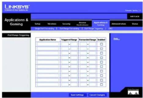
The Applications & Gaming Tab - Port Range Triggering
The Port Triggering screen allows the Router to watch outgoing data for specific port numbers. The IP address of the computer that sends the matching data is remembered by the Router, so that when the requested data returns through the Router, the data is sent to the proper computer by way of IP address and port mapping rules.
Port Triggering Range
Application Name. Enter the application name of the trigger.
Triggered Range. For each application, list the triggered port number range. Check with the Internet application documentation for the port number(s) needed. Enter the starting and ending port numbers of the Triggered Range.
Forwarded Range. For each application, list the forwarded port number range. Check with the Internet application documentation for the port number(s) needed. Enter the starting and ending port numbers of the Forward Range.
Enabled. Select Enabled to enable the application.
Change these settings as described here and click the Save Settings button to apply your changes or Cancel Changes to cancel your changes.
The Applications and Gaming Tab - DMZ
The DMZ feature allows one network user to be exposed to the Internet for use of a special-purpose service such as Internet gaming or videoconferencing. DMZ hosting forwards all the ports at the same time to one PC. The Port Range Forward feature is more secure because it only opens the ports you want to have opened, while DMZ hosting opens all the ports of one computer, exposing the computer to the Internet.
To expose one PC, select Enabled.
Source IP Address. If you want to allow any Internet IP address to access the exposed computer, select Any IP Address. If you want to allow a specific IP address or range of IP addresses to access the exposed computer, select the second option and enter the IP address or range of IP addresses in the fields provided.
Destination. Enter the IP address or MAC Address of the computer you want to expose.
Change these settings as described here and click the Save Settings button to apply your changes or Cancel Changes to cancel your changes.
text_image
LINKSYS A Division of Clear Systems, Inc. Applications & Gaming Setup Wireless Security Access Receivations Applications & Gaming Administration Status Single Port Forecasting Port Range Forecasting Port Range Trapping CALL Port Range Trigging Application Name Triggered Range Forwarded Range Enabled Save Settings Cancel Changes Data ServicesFigure 5-37: Applications and Gaming Tab - Port Triggering

text_image
LINKSYS® A software for client system, Inc. Applications & Gaming Setup Wireless Security Access Accessories Applications & Sending Administration Status Single Port Forwarding Port Range Forwarding Port Range Trapping Call D857 Installed Installed Service P Address: AppP Address Destination: P Address: 102 - 168.1.3 MAC Address: 0.0.0.0.0.0.0.0.0.0.0.0.0.0.0.0.0.0.0.0.0.0.0.0.0.0.0.0.0.0.0.0.0.0.0.0.0.0.0.0.0.0.0.0.0.0.0.0.0.0.0 Save Settings Cancel Changes Hill... Case SummaryFigure 5-38: Applications and Gaming Tab - DMZ
Wireless-G Broadband Router with RangeBooster
The Administration Tab - Management
This section of the Administration tab allows the network's administrator to manage specific Router functions for access and security.
Management
Router Access
Router Password and Re-enter to Confirm. You can change the Router's password from here. Enter a new Router password and then type it again in the Re-enter to Confirm field to confirm.
Web Access
Web Utility Access. HTTP (HyperText Transport Protocol) - The communications protocol used to connect to servers on the World Wide Web. HTTPS - Uses SSL (Secured Socket Layer) to encrypt data transmitted for higher security. Select HTTP or HTTPS.
Web Utility Access via Wireless. If you are using your Wireless Router in a public domain where you are giving wireless access to your guests, you can disable wireless access to the router's web-based utility. You will only be able to access the web-based utility via a wired connection if you disable the setting. Select Enable to enable wireless access to the Router's web-based utility or Disable to disable wireless access to the utility.
Remote Access

Note: When you are in a remote location and wish to manage the Router, enter http://
Remote Management. To access the Router remotely, from outside the local network, select Enabled. Otherwise, keep the default setting, Disabled.
Web Utility Access. HTTP (HyperText Transport Protocol) - The communications protocol used to connect to servers on the World Wide Web. HTTPS - Uses SSL (Secured Socket Layer) to encrypt data transmitted for higher security. Select HTTP or HTTPS.
Remote Upgrade. If you want to be able to upgrade the Router remotely, from outside the local network, select Enabled. (You must have the Remote Management feature enabled as well.) Otherwise, keep the default setting, Disabled.
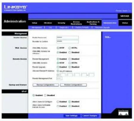
text_image
LINKAYS A Internet of Data Systems, INC. Administration Setup Access Security Access Description Authentication & Setting MANAGER Status Management User Accounts Private Password: No Add to Customers: Web Access Visibility Access Visibility Access via Privacy Provider Management Visibility Access Provider Updates Advanced Privacy P Address Provider Management Port Backup Configurations Provider Comparisons Backup Enabled Allow Users to Configur... Allow Users to Create Internet Access Enabled Enabled Enabled Enabled Cancel Settings Send Settings Cancel Changes Help...Figure 5-39: Administration Tab - Management
Wireless-G Broadband Router with RangeBooster
Allow Remote IP Address. If you want to be able to access the Router from any external IP address, select Any IP Address. If you want to specify an external IP address or range of IP addresses, then select the second option and complete the fields provided.
Remote Management Port. Enter the port number that will be open to outside access.
Backup and Restore
Backup Configurations. To back up the Router's configuration settings, click this button and follow the on-screen instructions.
Restore Configurations. To restore the Router's configuration settings, click this button and follow the on-screen instructions. (You must have previously backed up the Router's configuration.)
UPnP
Universal Plug and Play (UPnP) allows Windows Me and XP to automatically configure the Router for various Internet applications, such as gaming and videoconferencing.
UPnP. If you want to use UPnP, keep the default setting, Enabled. Otherwise, select Disabled.
Allow Users to Configure. Select Enabled, if you want to be able to make manual changes to the Router while using the UPnP feature. Otherwise, keep the default setting Disabled.
Allow Users to Disable Internet Access. Select Enabled, if you want to be able to prohibit any and all Internet connections. Otherwise, keep the default setting Disabled.
Change these settings as described here and click the Save Settings button to apply your changes or Cancel Changes to cancel your changes. Help information is shown on the right-hand side of the screen.
Wireless-G Broadband Router with RangeBooster
The Administration Tab - Log
The Router can keep logs of all traffic for your Internet connection.
Log
To disable the Log function, keep the default setting, Disabled. To monitor traffic between the network and the Internet, select Enabled.
Logviewer IP Address. For a permanent record of the Router's activity logs, Logviewer software must be used. This software can be downloaded from the Linksys website, www.linksys.com/international. The Log viewer saves all incoming and outgoing activity in a permanent file on your PC's hard drive. In the Logviewer IP Address field, enter the fixed IP address of the PC running the Log viewer software. The Router will now send updated logs to that PC.
View Log. When you wish to view the logs, click View Log. A new screen will appear. Select Incoming Log, Outgoing Log, Security Log, or DHCP Client Log. from the Type drop-down menu. The Incoming Log will display a temporary log of the Source IP Addresses and Port Numbers for the incoming Internet traffic. The Outgoing Log will display a temporary log of the Source IP Addresses, Destination IP Address and Port Numbers for the outgoing Internet traffic. The Security log will display the login information for the Web Utility. The DHCP Client Log will display the LAN DHCP server status information.
Click the Save the Log button to save this information to a file on your PC's hard drive. Click the Refresh button to update the log. Click the Clear button to clear all the information that is displayed.
Change these settings as described here and click the Save Settings button to apply your changes or Cancel Changes to cancel your changes.

text_image
LINKSYS® Administration Setup Wireless Security Access Access Application & Learning Address Only Status Log Enabled Enabled Logmaster P Address: 192.165.1.3 View Log Save Settings Cancel Changes Hill% Add SettingsFigure 5-40: Administration Tab - Log
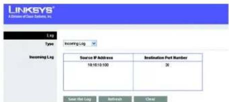
text_image
LINKKEYS® Aktion P/Star Networks, Inc. Lag Type Incoming Lg Incoming Lg Source IP Address 10.10.10.100 Destination Port Number 36 Save the Lag Refresh ClearFigure 5-41: Administration Tab - Incoming Log
Wireless-G Broadband Router with RangeBooster
The Administration Tab - Diagnostics
The Ping test allows you to check the status of your Internet connection.
Ping Test. The Ping test will check the status of a connection. Enter the address of the PC whose connection you wish to test, the packet size, and how many times you wish to test it. Then, click the Start to Ping button. The Ping screen will then display the test results. Click the Close button to return to the Diagnostics screen.
Traceroute Test. To test the performance of a connect, enter the address of the PC whose connection you wish to test and click the Start to Traceroute button. The Traceroute screen will then display the test results. Click the Close button to return to the Diagnostics screen.
Change these settings as described here and click the Save Settings button to apply your changes or Cancel Changes to cancel your changes.

text_image
LINKSYS A Division of Data Systems, Inc. Administration Setup Maintenance Currency Access New-Systems Applications & (www) Administration Status Management Log Disagglue Factory Products Package Logistics Outperform: 0% Freq Total IP or URL Address: Packet Size: 22 index(32-48500) Time to Freq: $ Start to Freq Translocate Text IP or URL Address: Start to Translocate Write... Data ServicesFigure 5-42: Administration Tab - Diagnostics

text_image
LINKSYS® A Division of Data Systems, Inc. Prep Irringing ravelo.com (216.09.12472) with 32 bytes of data Reply from 2161/08/12472 bytes=32 times=40ies TLS=46 CloseFigure 5-43: The Ping Test

text_image
LINKSYS® A Division of Data Systems, Inc. Tracing order to@yahoo.com [06.04.237: 08] +15 ms +10ms 10ms +9.56-gen=1#05.cisco.com [04.137.139.2] CloseFigure 5-44: The Traceroute Test
Chapter 6: Configuring the Wireless-G Broadband Router with RangeBooster The Administration Tab - Diagnostics
Wireless-G Broadband Router with RangeBooster
The Administration Tab - Factory Defaults
Click the Restore Factory Defaults button to reset all configuration settings to their default values. Any settings you have saved will be lost when the default settings are restored. This feature is disabled by default.
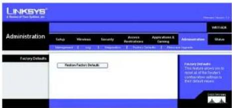
text_image
LINKSYS® A Member of New Systems, Inc. Administration Setup Wireless Security Access Applications Applications & Ceiling Administration Status Management Help Preparation Hardware Solutions Preparation History Factory Defaults Default Function Defaults Factory Defaults This material is designed to be easy at all the Customer's Documentation information in our Software Services List SummaryFigure 5-45: Administration Tab - Factory Defaults
The Administration Tab - Firmware Upgrade

Note: The Router will lose all of the settings you have customized. Before you upgrade its firmware, write down all of your custom settings. After you upgrade its firmware, you will have to re-enter all of your configuration settings.
Do not upgrade your firmware unless you are experiencing problems with the Router. For more information about upgrading firmware, refer to "Appendix C: Upgrading Firmware".
Before upgrading the firmware, download the Router's firmware upgrade file from the Linksys website, www.linksys.com/international. Then extract the file.
Please select a file to upgrade. In the field provided, enter the name of the extracted firmware upgrade file, or click the Browse button to find this file.
Start to Upgrade. After you have selected the appropriate file, click this button, and follow the on-screen instructions.
Help information is shown on the right-hand side of the screen.
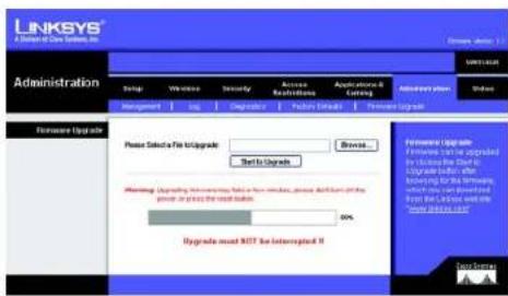
text_image
LINKSYS® A Domain of Data Systems, Inc. Administration Setup Winware Security Access Restrictions Applications & Settings Administrative User Status Management Edit Diagnostic Features Setup Performance Upgrade Formware Upgrade Please Select a File Upgrade Browse... Text to Upgrade Appearance Upgrade is upgraded by the following: The Software Upgrade will be added for the Windows, which can be provided by the Caturator. We have access to the Web Services (WIN) or to the Internet (IIP). You may change your website from www.lntec.com. Upgrade must NOT be interrupted if 0%Figure 5-46: Administration Tab - Firmware Upgrade
Wireless-G Broadband Router with RangeBooster
The Status Tab - Router
The Router screen on the Status Tab displays the Router's current status.
Router Information
Firmware Version. This is the Router's current firmware.
Current Time. This shows the time, as you set on the Setup Tab.
Internet MAC Address. This is the Router's MAC Address, as seen by your ISP.
Host Name. If required by your ISP, this would have been entered on the Setup Tab.
Domain Name. If required by your ISP, this would have been entered on the Setup Tab.
Internet Connection
Connection Type. This indicates the type of Internet connection you are using. If your Router has a PPPoE Internet connection, the PPPoE IP Connection screen will be displayed, which allows you to disconnect the connection.
Internet IP Address. The Router's Internet IP Address is displayed here.
Subnet Mask and Default Gateway. The Router's Subnet Mask and Default Gateway address are displayed here for DHCP and static IP connections.
DNS1-3. Shown here are the DNS (Domain Name System) IP addresses currently used by the Router.
MTU. MTU is the Maximum Transmission Unit. It specifies the largest packet size permitted for Internet transmission. The default setting, Manual, allows you to enter the largest packet size that will be transmitted. You should leave this value in the 1200 to 1500 range. To have the Router select the best MTU for your Internet connection, select Auto.
IP Address Release. Available for a DHCP connection, click this button to release the current IP address of the device connected to the Router's Internet port.
IP Address Renew. Available for a DHCP connection, click this button to replace the current IP address—of the device connected to the Router's Internet port—with a new IP address.
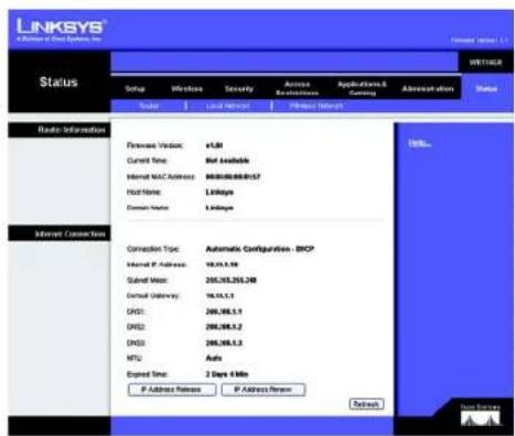
text_image
LINKSYS A Release of Data Systems Inc. Status: WNT1CA Setup Wireless Security Access Networks Applications & Comms Administration Status Scale Local Network Portfolio Network Rapid Information Firewire Version: v.68 Current Time: Not Available Internal MAC Address: 9030000000157 Host Name: L1@sgc Domain Name: L1@sgc Internet Connection Time Connection Type: Automatic Configuration - DHCP Internal IP Address: 19.15.1.10 Submit User: 205.165.205.240 Virtual Gateway: 19.15.1.1 DNS1: 205.165.1.1 DNS2: 205.165.1.2 DNS3: 205.165.1.3 MTU: Active Expired Time: 2 Days 4 Min IP Address Release IP Address Review Refresh...Figure 5-47: Status Tab - Router

text_image
LINKSYS® A Division of Data Systems, Inc. Status: Windows 1.1 MRT4208 Setup Wireless Security Access Accessories Application & Routing Administration Status User Local Network Hardware Services Router Information Firewalls Version: v1.88 Current Time: Not Available Internet MAC Address: 6000-8000-0157 Host Name: Linkages Domain Name: Linkages Internet Connection Connection Type: PPP4E Outset: Connected Internet IP Address: 10.10.1.10 Submit Mask: 205.205.255.248 Default Gateway: 10.10.1.1 ONEX: 200.200.1.1 ONEX2: 200.200.1.3 ONEX3: 200.200.1.3 Download Refresh Data ToolsFigure 5-48: Status Tab - Router with PPPoE IP Connection
Wireless-G Broadband Router with RangeBooster
Click the Refresh button to update the on-screen information. Help information is shown on the right-hand side of the screen.
The Status Tab - Local Network
The Local Network screen on the Status Tab displays the status of your network.
Local MAC Address. This is the Router's MAC Address, as seen on your local, Ethernet network.
Router IP Address. This shows the Router's IP Address, as it appears on your local, Ethernet network.
Subnet Mask. When the Router is using a Subnet Mask, it is shown here.
DHCP Server. If you are using the Router as a DHCP server, that will be displayed here.
Start IP Address. For the range of IP Addresses used by devices on your local, Ethernet network, the beginning of that range is shown here.
End IP Address. For the range of IP Addresses used by devices on your local, Ethernet network, the end of that range is shown here.
DHCP Clients Table. Clicking this button will open a screen to show you which PCs are utilizing the Router as a DHCP server. You can delete PCs from that list, and sever their connections, by clicking the Delete button.
The Status Tab - Wireless Network
The Wireless Network screen on the Status Tab displays the status of your wireless network.
MAC Address. This is the Router's MAC Address, as seen on your local, wireless network.
Mode. As selected from the Wireless tab, this will display the wireless mode (Mixed, Wireless-G Only, Wireless-B Only or Disabled) used by the network.
Network Name (SSID). As entered on the Wireless tab, this will display the wireless network name or SSID.
Channel. As entered on the Wireless tab, this will display the channel on which your wireless network is broadcasting.
Security. As selected on the Security Tab, this will display what type of encryption the Router uses for security.
Chapter 6: Configuring the Wireless-G Broadband Router with RangeBooster The Status Tab - Local Network
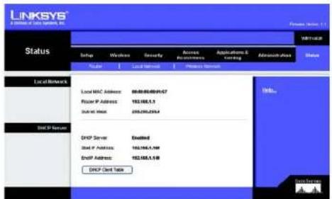
text_image
LINKSYS 2.1000000000000000000000000000000000000000000000000000000000000000000000000000000 Status Setup Windows Security Access Accessories Applications & Testing Administration Status Local MWC Address: 98-88-88-88-9457 Local P Address: 182-188-1,1 Dialal Mail: 255-256-256-4 DGP Server Enabled Dial P Address: 182-188-1,188 DGP Address: 182-188-1,188 DGP Card Data LinkSYS Data Services A/AFigure 5-49: Status Tab - Local Network

text_image
LINKSYS® A Division of Data Systems, Inc. DHCP Client Table To sort by: P Address Client Name Interface IP Address MAC Address Expired Time Linksys 1 LAN 192.168.1.100 00:40:05:35 CE6R 20x 56min/37sec Details Linksys 2 Wireless-A 192.168.1.101 00:40:05:35 CE6R 22m 56min/37sec Details Linksys 3 Wireless-G 192.168.1.102 00:40:05:35 CE6R 21m 56min/37sec Details Linksys 4 Wireless-B 192.168.1.103 00:40:05:35 CE6R 20x 56min/37sec Details Refresh CloseFigure 5-50: DHCP Clients Table

text_image
LINKSYS A Member of Day Systems, Inc. Status: Setup Wireless Security Access Authentication Applications & Carving Authentication Status: Scale Local Network Network Network Watts Network MAC Address: 自动拨号/0001-07 Work: Mixed Network Name (SSE) Relaps Channel: 8 - 2-0709s Security: WPA-Personal SSC Network: Enabled HUAFigure 5-51: Status Tab - Wireless Network
Wireless-G Broadband Router with RangeBooster
\*□□※■※■ ☆+ \*□□◆○※▲※□□▼※■※
This appendix consists of two parts: "Common Problems and Solutions" and "Frequently Asked Questions." Provided are possible solutions to problems that may occur during the installation and operation of the Router. Read the descriptions below to help you solve your problems. If you can't find an answer here, check the Linksys website at www.linksys.com/international.
Common Problems and Solutions
- I'm trying to access the Router's Web-based Utility, but I do not see the login screen. Instead, I see a screen saying, "404 Forbidden."
If you are using Windows Explorer, perform the following steps until you see the Web-based Utility's login screen (Netscape Navigator will require similar steps):
- Click File. Make sure Work Offline is NOT checked.
- Press CTRL + F5. This is a hard refresh, which will force Windows Explorer to load new webpages, not cached ones.
-
Click Tools. Click Internet Options. Click the Security tab. Click the Default level button. Make sure the security level is Medium or lower. Then click the OK button.
-
I need to set a static IP address on a PC.
You can assign a static IP address to a PC by performing the following steps:
• For Windows 98SE and Me:
- Click Start, Settings, and Control Panel. Double-click Network.
- In The following network components are installed box, select the TCP/IP-> associated with your Ethernet adapter. If you only have one Ethernet adapter installed, you will only see one TCP/IP line with no association to an Ethernet adapter. Highlight it and click the Properties button.
- In the TCP/IP properties window, select the IP address tab, and select Specify an IP address. Enter a unique IP address that is not used by any other computer on the network connected to the Router. Make sure that each IP address is unique for each PC or network device.
- Click the Gateway tab, and in the New Gateway prompt, enter 192.168.1.1, which is the default IP address of the Router. Click the Add button to accept the entry.
- Click the DNS tab, and make sure the DNS Enabled option is selected. Enter the Host and Domain names (e.g., John for Host and home for Domain). Enter the DNS entry provided by your ISP. If your ISP has not provided the DNS IP address, contact your ISP to get that information or go to its website for the information.
- Click the OK button in the TCP/IP properties window, and click Close or the OK button for the Network window.
- Restart the computer when asked.
Appendix A: Troubleshooting
Common Problems and Solutions
Wireless-G Broadband Router with RangeBooster
- For Windows 2000:
- Click Start, Settings, and Control Panel. Double-click Network and Dial-Up Connections.
- Right-click the Local Area Connection that is associated with the Ethernet adapter you are using, and select the Properties option.
- In the Components checked are used by this connection box, highlight Internet Protocol (TCP/IP), and click the Properties button. Select Use the following IP address option.
- Enter a unique IP address that is not used by any other computer on the network connected to the Router.
- Enter the Subnet Mask, 255.255.255.0.
- Enter the Default Gateway, 192.168.1.1 (Router's default IP address).
- Toward the bottom of the window, select Use the following DNS server addresses, and enter the Preferred DNS server and Alternative DNS server (provided by your ISP). Contact your ISP or go on its website to find the information.
- Click the OK button in the Internet Protocol (TCP/IP) Properties window, and click the OK button in the Local Area Connection Properties window.
- Restart the computer if asked.
- For Windows XP:
The following instructions assume you are running Windows XP with the default interface. If you are using the Classic interface (where the icons and menus look like previous Windows versions), please follow the instructions for Windows 2000.
- Click Start and Control Panel.
- Click the Network and Internet Connections icon and then the Network Connections icon.
- Right-click the Local Area Connection that is associated with the Ethernet adapter you are using, and select the Properties option.
- In the This connection uses the following items box, highlight Internet Protocol (TCP/IP). Click the Properties button.
- Enter a unique IP address that is not used by any other computer on the network connected to the Router.
- Enter the Subnet Mask. 255.255.255.0.
- Enter the Default Gateway, 192.168.1.1 (Router's default IP address).
- Toward the bottom of the window, select Use the following DNS server addresses, and enter the Preferred DNS server and Alternative DNS server (provided by your ISP). Contact your ISP or go on its website to find the information.
- Click the OK button in the Internet Protocol (TCP/IP) Properties window. Click the OK button in the Local Area Connection Properties window.
3. I want to test my Internet connection.
A Check your TCP/IP settings.
For Windows 98SE, Me, 2000, and XP:
• Refer to Windows Help for details. Make sure Obtain IP address automatically is selected in the settings.
Appendix A: Troubleshooting
Common Problems and Solutions
Wireless-G Broadband Router with RangeBooster
B Open a command prompt.
For Windows 98SE and Me:
- Click Start and Run. In the Open field, type command. Press the Enter key or click the OK button.
For Windows 2000 and XP:
- Click Start and Run. In the Open field, type cmd. Press the Enter key or click the OK button. In the command prompt, type ping 192.168.1.1 and press the Enter key.
- If you get a reply, the computer is communicating with the Router.
- If you do NOT get a reply, please check the cable, and make sure Obtain an IP address automatically is selected in the TCP/IP settings for your Ethernet adapter.
C In the command prompt, type ping followed by your Internet or WAN IP address and press the Enter key.
The Internet or WAN IP Address can be found on the Status screen of the Router's web-based utility. For example, if your Internet or WAN IP address is 1.2.3.4, you would enter ping 1.2.3.4 and press the Enter key.
- If you get a reply, the computer is connected to the Router.
- If you do NOT get a reply, try the ping command from a different computer to verify that your original computer is not the cause of the problem.
D In the command prompt, type ping www.yahoo.com and press the Enter key.
- If you get a reply, the computer is connected to the Internet. If you cannot open a webpage, try the ping command from a different computer to verify that your original computer is not the cause of the problem.
- If you do NOT get a reply, there may be a problem with the connection. Try the ping command from a different computer to verify that your original computer is not the cause of the problem.
4. I am not getting an IP address on the Internet with my Internet connection.
- Refer to "Problem #3, I want to test my Internet connection" to verify that you have connectivity.
- If you need to register the MAC address of your Ethernet adapter with your ISP, please see "Appendix E: Finding the MAC address and IP Address for Your Ethernet Adapter." If you need to clone the MAC address of your Ethernet adapter onto the Router, see the System section of "Chapter 6: Configuring the Wireless-G Broadband Router with RangeBooster" for details.
- Make sure you are using the right Internet connection settings. Contact your ISP to see if your Internet connection type is DHCP, Static IP Address, or PPPoE (commonly used by DSL consumers). Please refer to the Setup section of "Chapter 6: Configuring the Wireless-G Broadband Router with RangeBooster" for details on Internet connection settings.
- Make sure you have the right cable. Check to see if the Internet column has a solidly lit Link/Act LED.
- Make sure the cable connecting from your cable or DSL modem is connected to the Router's Internet port. Verify that the Status page of the Router's web-based utility shows a valid IP address from your ISP.
- Turn off the computer, Router, and cable/DSL modem. Wait 30 seconds, and then turn on the Router, cable/DSL modem, and computer. Check the Status tab of the Router's web-based utility to see if you get an IP address.
5. I am not able to access the Setup page of the Router's web-based utility.
- Refer to "Problem #3, I want to test my Internet connection" to verify that your computer is properly connected to the Router.
- Refer to "Appendix E: Finding the MAC Address and IP address for Your Ethernet Adapter" to verify that your computer has an IP Address, Subnet Mask, Gateway, and DNS.
- Set a static IP address on your system; refer to "Problem #2: I need to set a static IP address."
- Refer to "Problem #10: I am a PPPoE user, and I need to remove the proxy settings or the dial-up pop-up window."
6. I need to set up a server behind my Router and make it available to the public.
To use a server like a web, ftp, or mail server, you need to know the respective port numbers they are using. For example, port 80 (HTTP) is used for web; port 21 (FTP) is used for FTP, and port 25 (SMTP outgoing) and port 110 (POP3 incoming) are used for the mail server. You can get more information by viewing the documentation provided with the server you installed.
Follow these steps to set up port forwarding through the Router's web-based utility. We will be setting up web, ftp, and mail servers.
- Access the Router's web-based utility by going to http://192.168.1.1 or the IP address of the Router. Go to the Applications & Gaming => Port Range Forward tab.
- Enter any name you want to use for the Application.
- Enter the Start and End Port range of the service you are using. For example, if you have a web server, you would enter the range 80 to 80.
- Select the protocol(s) you will be using, TCP and/or UDP.
- Enter the IP address of the PC or network device that you want the port server to go to. For example, if the web server's Ethernet adapter IP address is 192.168.1.100, you would enter 100 in the field provided. Check "Appendix E: Finding the MAC Address and IP Address for Your Ethernet Adapter" for details on getting an IP address.
- Check the Enable option for the port services you want to use. Consider the example below:
| Application Start and End Protocol IP Address Enabled | |||
| Web server 80 to 80 Both 192.168.1.100 X | |||
| FTP server | 21 to 21 TCP | 192.168.1.101 X | |
| SMTP (outgoing) | 25 to 25 Both 192.168.1.102 X | ||
| POP3 (incoming) | 110 to 110 | Both 192.168.1.102 X | |
When you have completed the configuration, click the Save Settings button.
Wireless-G Broadband Router with RangeBooster
7. I need to set up online game hosting or use other Internet applications.
If you want to play online games or use Internet applications, most will work without doing any port forwarding or DMZ hosting. There may be cases when you want to host an online game or Internet application. This would require you to set up the Router to deliver incoming packets or data to a specific computer. This also applies to the Internet applications you are using. The best way to get the information on what port services to use is to go to the website of the online game or application you want to use. Follow these steps to set up online game hosting or use a certain Internet application:
- Access the Router's web interface by going to http://192.168.1.1 or the IP address of the Router. Go to the Applications & Gaming => Port Range Forward tab.
- Enter any name you want to use for the Application.
- Enter the Start and End Port range of the service you are using. For example, if you want to host Unreal Tournament (UT), you would enter the range 7777 to 27900.
- Select the protocol(s) you will be using, TCP and/or UDP.
- Enter the IP address of the PC or network device that you want the port server to go to. For example, if the web server's Ethernet adapter IP address is 192.168.1.100, you would enter 100 in the field provided. Check "Appendix E: Finding the MAC Address and IP Address for Your Ethernet Adapter" for details on getting an IP address.
- Check the Enable option for the port services you want to use. Consider the example below:
| Application Start and End Protocol IP Address Enabled | ||||
| UT 7777 to 27900 Both 192.168.1.100 X | ||||
| Halflife 27015 to 27015 Both 192.168.1.105 X | ||||
| PC Anywhere | 5631 to 5631 | UDP | 192.168.1.102 | X |
| VPN IPSEC | 500 to 500 UDP | 192.168.1.100 X | ||
When you have completed the configuration, click the Save Settings button.
8. I can't get the Internet game, server, or application to work.
If you are having difficulties getting any Internet game, server, or application to function properly, consider exposing one PC to the Internet using DeMilitarized Zone (DMZ) hosting. This option is available when an application requires too many ports or when you are not sure which port services to use. Make sure you disable all the forwarding entries if you want to successfully use DMZ hosting, since forwarding has priority over DMZ hosting. (In other words, data that enters the Router will be checked first by the forwarding settings. If the port number that the data enters from does not have port forwarding, then the Router will send the data to whichever PC or network device you set for DMZ hosting.)
Wireless-G Broadband Router with RangeBooster
Follow these steps to set DMZ hosting:
- Access the Router's web-based utility by going to http://192.168.1.1 or the IP address of the Router. Go to the Applications & Gaming => Port Range Forward tab.
- Disable or remove the entries you have entered for forwarding. Keep this information in case you want to use it at a later time.
- Go to the Applications & Gaming => DMZ tab.
- Select Enable next to DMZ. In the Client PC IP Address field, enter the IP address of the computer you want exposed to the Internet. This will bypass the NAT technology for that computer. Please refer to "Appendix E: Finding the MAC Address and IP Address for Your Ethernet Adapter" for details on getting an IP address.
- Once completed with the configuration, click the Save Settings button.
9. I forgot my password, or the password prompt always appears when I am saving settings to the Router.
Reset the Router to factory default by pressing the Reset button for 10 seconds and then releasing it. If you are still getting prompted for a password when saving settings, then perform the following steps:
- Access the Router's web-based utility by going to http://192.168.1.1 or the IP address of the Router. Enter the default password admin, and click the Administration => Management tab.
- Enter a different password in the Router Password field, and enter the same password in the second field to confirm the password.
- Click the Save Settings button.
10. I am a PPPoE user, and I need to remove the proxy settings or the dial-up pop-up window.
If you have proxy settings, you need to disable these on your computer. Because the Router is the gateway for the Internet connection, the computer does not need any proxy settings to gain access. Please follow these directions to verify that you do not have any proxy settings and that the browser you use is set to connect directly to the LAN.
- For Microsoft Internet Explorer 5.0 or higher:
- Click Start, Settings, and Control Panel. Double-click Internet Options.
- Click the Connections tab.
- Click the LAN settings button and remove anything that is checked.
- Click the OK button to go back to the previous screen.
- Click the option Never dial a connection. This will remove any dial-up pop-ups for PPPoE users.
- For Netscape 4.7 or higher:
- Start Netscape Navigator, and click Edit, Preferences, Advanced, and Proxies.
- Make sure you have Direct connection to the Internet selected on this screen.
- Close all the windows to finish.
Wireless-G Broadband Router with RangeBooster
11. To start over, I need to set the Router to factory default.
Hold the Reset button for 10 seconds and then release it. This will return the password, forwarding, and other settings on the Router to the factory default settings. In other words, the Router will revert to its original factory configuration.
12.I need to upgrade the firmware.
In order to upgrade the firmware with the latest features, you need to go to the Linksys website and download the latest firmware at www.linksys.com/international.
Follow these steps:
- Go to the Linksys website at http://www.linksys.com/international and download the latest firmware.
- To upgrade the firmware, follow the steps in "Appendix C: Upgrading Firmware."
13. The firmware upgrade failed, and/or the Power LED is flashing.
The upgrade could have failed for a number of reasons. Follow these steps to upgrade the firmware and/or make the Power LED stop flashing:
- If the firmware upgrade failed, use the TFTP program (it was downloaded along with the firmware). Open the pdf that was downloaded along with the firmware and TFTP program, and follow the pdf's instructions.
- Set a static IP address on the PC; refer to "Problem #2, I need to set a static IP address." Use the following IP address settings for the computer you are using:
IP Address: 192.168.1.50
Subnet Mask: 255.255.255.0
Gateway: 192.168.1.1
- Perform the upgrade using the TFTP program or the Administration tab of the Router's web-based utility.
14.My DSL service's PPPoE is always disconnecting.
PPPoE is not actually a dedicated or always-on connection. The DSL ISP can disconnect the service after a period of inactivity, just like a normal phone dial-up connection to the Internet.
- There is a setup option to “keep alive” the connection. This may not always work, so you may need to re-establish connection periodically.
- To connect to the Router, go to the web browser, and enter http://192.168.1.1 or the IP address of the Router.
- Enter the password, if asked. (The default password is admin.)
- On the Setup screen, select the option Keep Alive, and set the Redial Period option at 20 (seconds).
- Click the Save Settings button.
- Click the Status tab, and click the Connect button.
- You may see the login status display as Connecting. Press the F5 key to refresh the screen, until you see the login status display as Connected.
- Click the Save Settings button to continue.
- If the connection is lost again, follow steps 1-6 to re-establish connection.
Appendix A: Troubleshooting
Common Problems and Solutions
Wireless-G Broadband Router with RangeBooster
15.I can't access my e-mail, web or I am getting corrupted data from the Internet.
The Maximum Transmission Unit (MTU) setting may need to be adjusted. By default, the MTU is set at 1500. For most DSL users, it is strongly recommended to use MTU 1492.
- If you are having some difficulties, perform the following steps:
-
To connect to the Router, go to the web browser, and enter http://192.168.1.1 or the IP address of the Router.
-
Enter the password, if asked. (The default password is admin.)
-
Look for the MTU option, and select Manual. In the Size field, enter 1492.
-
Click the Save Settings button to continue.
- If your difficulties continue, change the Size to different values. Try this list of values, one value at a time, in this order, until your problem is solved:
1462
1400
1362
1300
16. The Power LED keeps flashing.
The Power LED flashes when the device is first powered up. Meantime, the system will boot up itself and check for proper operation. After finishing the checking procedure, the LED stays solid to show that the system is working fine. If the LED keeps flashing after this time, the device is not working properly. Try to flash the firmware by assigning a static IP address to the computer, and then upgrade the firmware. Try using the following settings, IP Address: 192.168.1.50 and Subnet Mask: 255.255.255.0.
17. When I enter a URL or IP address, I get a time-out error or am prompted to retry.
- Check if other PCs work. If they do, ensure that your workstation's IP settings are correct (IP Address, Subnet Mask, Default Gateway, and DNS). Restart the computer that is having a problem.
- If the PCs are configured correctly, but still not working, check the Router. Ensure that it is connected and powered on. Connect to it and check its settings. (If you cannot connect to it, check the LAN and power connections.)
- If the Router is configured correctly, check your Internet connection (DSL/cable modem, etc.) to see if it is working correctly. You can remove the Router to verify a direct connection.
- Manually configure the TCP/IP settings with a DNS address provided by your ISP.
- Make sure that your browser is set to connect directly and that any dial-up is disabled. For Internet Explorer, click Tools, Internet Options, and then the Connection tab. Make sure that Internet Explorer is set to Never dial a connection. For Netscape Navigator, click Edit, Preferences, Advanced, and Proxy. Make sure that Netscape Navigator is set to Direct connection to the Internet.
Wireless-G Broadband Router with RangeBooster
Frequently Asked Questions
What is the maximum number of IP addresses that the Router will support?
The Router will support up to 253 IP addresses.
Is IPSec Pass-Through supported by the Router?
Yes, it is a built-in feature that the Router automatically enables.
Where is the Router installed on the network?
In a typical environment, the Router is installed between the cable/DSL modem and the LAN. Plug the Router into the cable/DSL modem's Ethernet port.
Does the Router support IPX or AppleTalk?
No. TCP/IP is the only protocol standard for the Internet and has become the global standard for communications. IPX, a NetWare communications protocol used only to route messages from one node to another, and AppleTalk, a communications protocol used on Apple and Macintosh networks, can be used for LAN to LAN connections, but those protocols cannot connect from the Internet to a LAN.
Appendix A: Troubleshooting
Frequently Asked Questions
Wireless-G Broadband Router with RangeBooster
Does the Internet connection of the Router support 100Mbps Ethernet?
The Router's current hardware design supports up to 100Mbps Ethernet on its Internet port; however, the Internet connection speed will vary depending on the speed of your broadband connection. The Router also supports 100Mbps over the auto-sensing Fast Ethernet 10/100 switch on the LAN side of the Router.
What is Network Address Translation and what is it used for?
Network Address Translation (NAT) translates multiple IP addresses on the private LAN to one public address that is sent out to the Internet. This adds a level of security since the address of a PC connected to the private LAN is never transmitted on the Internet. Furthermore, NAT allows the Router to be used with low cost Internet accounts, such as DSL or cable modems, when only one TCP/IP address is provided by the ISP. The user may have many private addresses behind this single address provided by the ISP.
Does the Router support any operating system other than Windows 98SE, Windows Millennium, Windows 2000, or Windows XP?
Yes, but Linksys does not, at this time, provide technical support for setup, configuration or troubleshooting of any non-Windows operating systems.
Does the Router support ICQ send file?
Yes, with the following fix: click ICQ menu -> preference -> connections tab->, and check I am behind a firewall or proxy. Then set the firewall time-out to 80 seconds in the firewall setting. The Internet user can then send a file to a user behind the Router.
I set up an Unreal Tournament Server, but others on the LAN cannot join. What do I need to do?
If you have a dedicated Unreal Tournament server running, you need to create a static IP for each of the LAN computers and forward ports 7777, 7778, 7779, 7780, 7781, and 27900 to the IP address of the server. You can also use a port forwarding range of 7777 \~ 27900. If you want to use the UT Server Admin, forward another port. (Port 8080 usually works well but is used for remote admin. You may have to disable this.) Then in the [UWeb.WebServer] section of the server.ini file, set the ListenPort to 8080 (to match the mapped port above) and ServerName to the IP assigned to the Router from your ISP.
Can multiple gamers on the LAN get on one game server and play simultaneously with just one public IP address?
It depends on which network game or what kind of game server you are using. For example, Unreal Tournament supports multi-login with one public IP.
How do I get Half-Life: Team Fortress to work with the Router?
The default client port for Half-Life is 27005. The computers on your LAN need to have "+clientport 2700x" added to the HL shortcut command line; the x would be 6, 7, 8, and on up. This lets multiple computers connect to the same server. One problem: Version 1.0.1.6 won't let multiple computers with the same CD key connect at
Appendix A: Troubleshooting
Frequently Asked Questions
Wireless-G Broadband Router with RangeBooster
the same time, even if on the same LAN (not a problem with 1.0.1.3). As far as hosting games, the HL server does not need to be in the DMZ. Just forward port 27015 to the local IP address of the server computer.
How can I block corrupted FTP downloads?
If you are experiencing corrupted files when you download a file with your FTP client, try using another FTP program.
The web page hangs; downloads are corrupt, or nothing but junk characters are being displayed on the screen. What do I need to do?
Force your Ethernet adapter to 10Mbps or half duplex mode, and turn off the "Auto-negotiate" feature of your Ethernet adapter as a temporary measure. (Please look at the Network Control Panel in your Ethernet adapter's Advanced Properties tab.) Make sure that your proxy setting is disabled in the browser. Check our website at www.linksys.com/international for more information.
If all else fails in the installation, what can I do?
Reset the Router by holding down the reset button until the Power LED fully turns on and off. Reset your cable or DSL modem by powering the unit off and then on. Obtain and flash the latest firmware release that is readily available on the Linksys website, www.linksys.com/international.
How will I be notified of new Router firmware upgrades?
All Linksys firmware upgrades are posted on the Linksys website at www.linksys.com/international, where they can be downloaded for free. To upgrade the Router's firmware, use the Administration - Firmware Upgrade tab of the Router's web-based utility. If the Router's Internet connection is working well, there is no need to download a newer firmware version, unless that version contains new features that you would like to use. Downloading a more current version of Router firmware will not enhance the quality or speed of your Internet connection, and may disrupt your current connection stability.
Will the Router function in a Macintosh environment?
Yes, but the Router's setup pages are accessible only through Internet Explorer 4.0 or Netscape Navigator 4.0 or higher for Macintosh.
I am not able to get the web configuration screen for the Router. What can I do?
You may have to remove the proxy settings on your Internet browser, e.g., Netscape Navigator or Internet Explorer. Or remove the dial-up settings on your browser. Check with your browser documentation, and make sure that your browser is set to connect directly and that any dial-up is disabled. Make sure that your browser is set to connect directly and that any dial-up is disabled. For Internet Explorer, click Tools, Internet Options, and then the Connection tab. Make sure that Internet Explorer is set to Never dial a connection. For Netscape Navigator, click Edit, Preferences, Advanced, and Proxy. Make sure that Netscape Navigator is set to Direct connection to the Internet.
Appendix A: Troubleshooting
Frequently Asked Questions
Wireless-G Broadband Router with RangeBooster
What is DMZ Hosting?
Demilitarized Zone (DMZ) allows one IP address (computer) to be exposed to the Internet. Some applications require multiple TCP/IP ports to be open. It is recommended that you set your computer with a static IP if you want to use DMZ Hosting. To get the LAN IP address, see "Appendix E: Finding the MAC Address and IP Address for Your Ethernet Adapter."
If DMZ Hosting is used, does the exposed user share the public IP with the Router? No.
Does the Router pass PPTP packets or actively route PPTP sessions?
The Router allows PPTP packets to pass through.
Is the Router cross-platform compatible?
Any platform that supports Ethernet and TCP/IP is compatible with the Router.
How many ports can be simultaneously forwarded?
Theoretically, the Router can establish 520 sessions at the same time, but you can only forward 10 ranges of ports.
What are the advanced features of the Router?
The Router's advanced features include advanced wireless settings, filters, access restriction policies, port forwarding, advanced routing, and DDNS.
How do I get mIRC to work with the Router?
Under the Port Forwarding tab, set port forwarding to 113 for the PC on which you are using mIRC.
Can the Router act as my DHCP server?
Yes. The Router has DHCP server software built-in.
Can I run an application from a remote computer over the wireless network?
This will depend on whether or not the application is designed to be used over a network. Consult the application's documentation to determine if it supports operation over a network.
What is the IEEE 802.11g standard?
It is one of the IEEE standards for wireless networks. The 802.11g standard allows wireless networking hardware from different manufacturers to communicate, provided that the hardware complies with the 802.11g standard. The 802.11g standard states a maximum data transfer rate of 54Mbps and an operating frequency of 2.4GHz.
Appendix A: Troubleshooting
Frequently Asked Questions
Wireless-G Broadband Router with RangeBooster
What is the IEEE 802.11b standard?
It is one of the IEEE standards for wireless networks. The 802.11b standard allows wireless networking hardware from different manufacturers to communicate, provided that the hardware complies with the 802.11b standard.
The 802.11b standard states a maximum data transfer rate of 11Mbps and an operating frequency of 2.4GHz.
What IEEE 802.11g features are supported?
The product supports the following IEEE 802.11g functions:
• CSMA/CA plus Acknowledge protocol
• OFDM protocol
• Multi-Channel Roaming
• Automatic Rate Selection
- RTS/CTS feature
- Fragmentation
• Power Management
What IEEE 802.11b features are supported?
The product supports the following IEEE 802.11b functions:
• CSMA/CA plus Acknowledge protocol
• Multi-Channel Roaming
• Automatic Rate Selection
- RTS/CTS feature
- Fragmentation
• Power Management
What is ad-hoc mode?
When a wireless network is set to ad-hoc mode, the wireless-equipped computers are configured to communicate directly with each other. The ad-hoc wireless network will not communicate with any wired network.
What is infrastructure mode?
When a wireless network is set to infrastructure mode, the wireless network is configured to communicate with a wired network through a wireless access point.
What is roaming?
Roaming is the ability of a portable computer user to communicate continuously while moving freely throughout an area greater than that covered by a single access point. Before using the roaming function, the workstation must make sure that it is the same channel number with the access point of dedicated coverage area.
To achieve true seamless connectivity, the wireless LAN must incorporate a number of different functions. Each node and access point, for example, must always acknowledge receipt of each message. Each node must
Appendix A: Troubleshooting
Frequently Asked Questions
Wireless-G Broadband Router with RangeBooster
maintain contact with the wireless network even when not actually transmitting data. Achieving these functions simultaneously requires a dynamic RF networking technology that links access points and nodes. In such a system, the user's end node undertakes a search for the best possible access to the system. First, it evaluates such factors as signal strength and quality, as well as the message load currently being carried by each access point and the distance of each access point to the wired backbone. Based on that information, the node next selects the right access point and registers its address. Communications between end node and host computer can then be transmitted up and down the backbone.
As the user moves on, the end node's RF transmitter regularly checks the system to determine whether it is in touch with the original access point or whether it should seek a new one. When a node no longer receives acknowledgment from its original access point, it undertakes a new search. Upon finding a new access point, it then re-registers, and the communication process continues.
What is ISM band?
The FCC and their counterparts outside of the U.S. have set aside bandwidth for unlicensed use in the ISM (Industrial, Scientific and Medical) band. Spectrum in the vicinity of 2.4 GHz, in particular, is being made available worldwide. This presents a truly revolutionary opportunity to place convenient high-speed wireless capabilities in the hands of users around the globe.
What is Spread Spectrum?
Spread Spectrum technology is a wideband radio frequency technique developed by the military for use in reliable, secure, mission-critical communications systems. It is designed to trade off bandwidth efficiency for reliability, integrity, and security. In other words, more bandwidth is consumed than in the case of narrowband transmission, but the trade-off produces a signal that is, in effect, louder and thus easier to detect, provided that the receiver knows the parameters of the spread-spectrum signal being broadcast. If a receiver is not tuned to the right frequency, a spread-spectrum signal looks like background noise. There are two main alternatives, Direct Sequence Spread Spectrum (DSSS) and Frequency Hopping Spread Spectrum (FHSS).
What is DSSS? What is FHSS? And what are their differences?
Frequency-Hopping Spread-Spectrum (FHSS) uses a narrowband carrier that changes frequency in a pattern that is known to both transmitter and receiver. Properly synchronized, the net effect is to maintain a single logical channel. To an unintended receiver, FHSS appears to be short-duration impulse noise. Direct-Sequence Spread-Spectrum (DSSS) generates a redundant bit pattern for each bit to be transmitted. This bit pattern is called a chip (or chipping code). The longer the chip, the greater the probability that the original data can be recovered. Even if one or more bits in the chip are damaged during transmission, statistical techniques embedded in the radio can recover the original data without the need for retransmission. To an unintended receiver, DSSS appears as low power wideband noise and is rejected (ignored) by most narrowband receivers.
Appendix A: Troubleshooting
Frequently Asked Questions
Wireless-G Broadband Router with RangeBooster
What is WEP?
WEP is Wired Equivalent Privacy, a data privacy mechanism based on a 64-bit or 128-bit shared key algorithm, as described in the IEEE 802.11 standard.
What is a MAC Address?
The Media Access Control (MAC) address is a unique number assigned by the manufacturer to any Ethernet networking device, such as a network adapter, that allows the network to identify it at the hardware level. For all practical purposes, this number is usually permanent. Unlike IP addresses, which can change every time a computer logs onto the network, the MAC address of a device stays the same, making it a valuable identifier for the network.
How do I reset the Router?
Press the Reset button on the back panel for about five seconds. This will reset the Router to its default settings.
How do I resolve issues with signal loss?
There is no way to know the exact range of your wireless network without testing. Every obstacle placed between the Router and a wireless PC will create signal loss. Lead glass, metal, concrete floors, water and walls will inhibit the signal and reduce range. Start with the Router and your wireless PC in the same room and move it away in small increments to determine the maximum range in your environment.
You may also try using different channels, as this may eliminate interference affecting only one channel.
I have excellent signal strength, but I cannot see my network.
Wireless security is probably enabled on the Router, but not on your wireless adapter (or vice versa). Verify that the same wireless security method and passphrase/keys are being used on all devices of your wireless network.
How many channels/frequencies are available with the Router?
There are eleven channels, ranging from 1 to 11 in most of North, Central, and South America, and thirteen channels, ranging from 1 to 13, in most of Europe and Asia. There may be additional channels available in other regions, subject to the regulations of your region and/or country.
If your questions are not addressed here, refer to the Linksys website, www.linksys.com/international.
Appendix A: Troubleshooting
Frequently Asked Questions
Wireless-G Broadband Router with RangeBooster
\*□□■■■+★□□□▲\*\*◆□▼
Linksys wants to make wireless networking as safe and easy for you as possible. The current generation of Linksys products provide several network security features, but they require specific action on your part for implementation. So, keep the following in mind whenever you are setting up or using your wireless network.
Security Precautions
The following is a complete list of security precautions to take (at least steps 1 through 5 should be followed):
- Change the default SSID.
- Disable SSID Broadcast.
- Change the default password for the Administrator account.
- Enable MAC Address Filtering.
- Change the SSID periodically.
- Use the highest encryption algorithm possible. Use WPA if it is available. Please note that this may reduce your network performance.
- Change the WEP encryption keys periodically.
For information on implementing these security features, refer to "Chapter 6: Configuring the Wireless-G Broadband Router with RangeBooster."
Security Threats Facing Wireless Networks
Wireless networks are easy to find. Hackers know that in order to join a wireless network, wireless networking products first listen for "beacon messages". These messages can be easily decrypted and contain much of the network's information, such as the network's SSID (Service Set Identifier). Here are the steps you can take:
Change the administrator's password regularly. With every wireless networking device you use, keep in mind that network settings (SSID, WEP keys, etc.) are stored in its firmware. Your network administrator is the only person who can change network settings. If a hacker gets a hold of the administrator's password, he, too, can change those settings. So, make it harder for a hacker to get that information. Change the administrator's password regularly.
Appendix B: Wireless Security Security Precautions

NOTE: Some of these security features are available only through the network router or access point. Refer to the router or access point's documentation for more information.
Wireless-G Broadband Router with RangeBooster
SSID. There are several things to keep in mind about the SSID:
- Disable Broadcast
- Make it unique
- Change it often
Most wireless networking devices will give you the option of broadcasting the SSID. While this option may be more convenient, it allows anyone to log into your wireless network. This includes hackers. So, don't broadcast the SSID.
Wireless networking products come with a default SSID set by the factory. (The Linksys default SSID is "linksys".) Hackers know these defaults and can check these against your network. Change your SSID to something unique and not something related to your company or the networking products you use.
Change your SSID regularly so that any hackers who have gained access to your wireless network will have to start from the beginning in trying to break in.
MAC Addresses. Enable MAC Address filtering. MAC Address filtering will allow you to provide access to only those wireless nodes with certain MAC Addresses. This makes it harder for a hacker to access your network with a random MAC Address.
WEP Encryption. Wired Equivalent Privacy (WEP) is often looked upon as a cure-all for wireless security concerns. This is overstating WEP's ability. Again, this can only provide enough security to make a hacker's job more difficult.
There are several ways that WEP can be maximized:
- Use the highest level of encryption possible
- Use "Shared Key" authentication
- Change your WEP key regularly
WPA. Wi-Fi Protected Access (WPA) is the newest and best available standard in Wi-Fi security. Two modes are available: WPA Personal and WPA Enterprise. WPA Personal gives you a choice of two encryption methods: TKIP (Temporal Key Integrity Protocol), which utilizes a stronger encryption method and incorporates Message Integrity Code (MIC) to provide protection against hackers, and AES (Advanced Encryption System), which utilizes a symmetric 128-Bit block data encryption. WPA Enterprise uses TKIP or AES encryption and utilizes a RADIUS (Remote Authentication Dial-In User Service) server for authentication.

IMPORTANT: Always remember that each device in your wireless network MUST use the same encryption method and encryption key or your wireless network will not function properly.
Wireless-G Broadband Router with RangeBooster
WPA Personal. Select the type of encryption, TKIP or AES, enter a Passphrase (pre-shared key) of 8-64 characters, and enter a Key Renewal period time between 0 and 99,999 seconds, which instructs the Router or other device how often it should change the encryption keys.
WPA Enterprise. WPA used in coordination with a RADIUS server. (This should only be used when a RADIUS server is connected to the Router or other device.) First, select the type of WPA encryption, TKIP or AES. Enter the RADIUS server's IP Address and port number, along with a key shared between the device and the server. Last, enter a Key Renewal period, which instructs the device how often it should change the encryption keys.
RADIUS. WEP used in coordination with a RADIUS server. (This should only be used when a RADIUS server is connected to the Router or other device.) First, enter the RADIUS server's IP Address and port number, along with a shared secret (authentication key) shared between the device and the server. Then, select a WEP key and a level of WEP encryption, and either generate a WEP key through the Passphrase or enter the WEP key manually. Then, select a Tx key.
Implementing encryption may have a negative impact on your network's performance, but if you are transmitting sensitive data over your network, encryption should be used.
These security recommendations should help keep your mind at ease while you are enjoying the most flexible and convenient technology Linksys has to offer.
Wireless-G Broadband Router with RangeBooster
\*□□※■※■◆+※□※□※※■◆□○○○○
The Router's firmware is upgraded through the Web-based Utility's Administration tab. Follow these instructions:
- Download the firmware from Linksys's website at www.linksys.com/international.
- Extract the firmware file on your computer.
- Open the Router's Web-based Utility, and click the Administration tab.
- Click Firmware Upgrade, and the Upgrade Firmware screen will appear.
- Enter the location of the firmware's file or click the Browse button to find the file.
- Then click the Upgrade button and follow the on-screen instructions.

text_image
LINKSYS® A Division of Data Systems, Inc. Please select a File by Upgrade Start to Upgrade Upgrade: Upgrade must not be interrupted if Upgrade should not be completed or complete. Upgrade should not be completed or complete. Upgrade should not be completed or complete. Upgrade should not be completed or complete. Upgrade should not be completed or complete. Upgrade should not be completed or complete. Upgrade should not be completed or complete. Upgrade should not be completed or complete. Upgrade should not be completed or complete. Upgrade should not be completed or complete. Upgrade should not be completed or complete. Upgrade should not be completed or complete. Upgrade should not be completed or complete. Upgrade should not have been completed or complete. Upgrade should not have been completed or complete. Upgrade should not have been completed or complete. Upgrade should not have been completed or complete. Upgrade should not have been completed or complete. Upgrade should not have been completed or complete. Upgrade should not have been completed or complete. Upgrade should not have been completed or complete. Upgrade should not have been completed or complete. Upgrade should not have been completed or complete. Upgrade should not have been completed or complete. Upgrade should not have been completely completed or complete. Upgrade should not have been completely completed or complete. Upgrade should not have been completely completed or complete. Upgrade should not have been completely completed or complete. Upgrade should not have been completely completed or complete. Upgrade should not have been completely completed or complete. Upgrade should not have been completely completed or complete. Upgrade should not have been completely completed or complete. Upgrade should not have been completely completed or complete. Upgrade should not have been completely completed or complete. Upgrade should not have been completed or complete. Upgrade should not have been completely completed or complete. Upgrade should not have been completely completed or complete. Upgrade should not have been completely completed or complete. Upgrade should not have been completely completed or complete. Upgrade should not have been completely completed or complete. Upgrade should not have been completely completed or complete. Upgrade should not have been completely completed or complete. Upgrade should not have been completely completed or complete. Upgrade should not have been completely completion or complete. Upgrade should not have been completely completed or complete. Upgrade should not have been completely completion or complete. Upgrade should not have been completely completion or complete. Upgrade should not have been completely completion or complete. Upgrade should not have been completely completion or complete. Upgrade should not have been completely completion or complete. Upgrade should not have been completely completion or complete. Upgrade should not have been completely completion or complete. Upgrade should not have been completely completion or complete. Upgrade should not have been completely completion or complete. Upgrade should not have been completely completion or complete. Upgrade should not have been completely completed or complete. Upgrade should not have been completely completion or complete. Upgrade should not have been completely completion or complete. Upgrade should not have been completely completion or complete. Upgrade should not have been completely completion or complete. Upgrade should not have been completely completion or complete. Upgrade should not have been completely completion or complete. Upgrade should not have been completely completion or complete. Upgrade should not have been completely completed or complete. Upgrade should not have been completely completion or complete. Upgrade should not have been completely completed or complete. Upgrade should not have been completely completion or complete. Upgrade should not have been completely completion or complete. Upgrade should not have been completely completion or complete. Upgrade should not have been completely completion or complete. Upgrade should not have been completely completion or complete. Upgrade should not have been completely completion or complete. Upgrade should not have been completely completed or complete. Upgrade should not have been completely completion or complete. Upgrade should not have been completely completion or complete. Upgrade should not have been completely completed or complete. Upgrade should not have been completely completion or complete. Upgrade should not have been completely completion or complete. Upgrade should not have been completely completion or complete. Upgrade should not have been completely completion or complete. Upgrade should not have been completely completion or complete. Upgrade should not have been completely completion or complete. Upgrade should not have been completely completed or complete. Upgrade should not have been completely completed or complete. Upgrade should not have been completely completion or complete. Upgrade should not have been completely completion or complete. Upgrade should not have been completely completion or complete. Upgrade should not have been completely completion or complete. Upgrade should not have been completely completion or complete. Upgrade should not have been completely completion or complete. Upgrade should not have been completely completion or complete. Upgrade should not have been completely completion or complete. Upgrade should not have been completely completed or complete. Upgrade should not have been completely completed or complete. Upgrade should not have been completely completion or complete. Upgrade should not have been completely completed or complete. Upgrade should not have been completely completion or complete. Upgrade should not have been completely completion or complete. Upgrade should not have been completely completion or complete. Upgrade should not have been completely completion or complete. Upgrade should not have been completely completion or complete. Upgrade should not have been completely completed or complete. Upgrade should not have been completely completion or complete. Upgrade should not have been completely completion or complete. Upgrade should not have been completely completion or complete. Upgrade should not have been completely completed or complete. Upgrade should not have been completely completion or complete. Upgrade should not have been completely completion or complete. Upgrade should not have been completely completion or complete. Upgrade should not have been completely completion or complete. Upgrade should not have been completely completion or complete. Upgrade should not have been completely completed or complete. Upgrade should not have been completely completion or complete. Upgrade should not have been completely completed or complete. Upgrade should not have been completely completion or complete. Upgrade should not have been completely completed or complete. Upgrade should not have been completely completion or complete. Upgrade should not have been completely completion or complete. Upgrade should not have been completely completion or complete. Upgrade should not have been completely completion or complete. Upgrade should not have been completely completion or complete. Upgrade should not have been completely completed or complete. Upgrade should not have been completely completed or complete Upgrade should not have been completely completion/are 80% Upgrade should NOT be interrupted ifFigure C-1: Upgrade Firmware
Wireless-G Broadband Router with RangeBooster

Almost Linksys wireless products require Microsoft Windows. Windows is the most used operating system in the world and comes with many features that help make networking easier. These features can be accessed through Windows Help and are described in this appendix.
TCP/IP
Before a computer can communicate with the Router, TCP/IP must be enabled. TCP/IP is a set of instructions, or protocol, all PCs follow to communicate over a network. This is true for wireless networks as well. Your PCs will not be able to utilize wireless networking without having TCP/IP enabled. Windows Help provides complete instructions on enabling TCP/IP.
Shared Resources
If you wish to share printers, folder, or files over your network, Windows Help provides complete instructions on utilizing shared resources.
Network Neighborhood/My Network Places
Other PCs on your network will appear under Network Neighborhood or My Network Places (depending upon the version of Windows you're running). Windows Help provides complete instructions on adding PCs to your network.
Wireless-G Broadband Router with RangeBooster

text_image
Collection of symbolic and stylized icons including stars, squares, and triangles with varying fill patternsThis section describes how to find the MAC address for your computer's Ethernet adapter so you can use the MAC filtering and/or MAC address cloning feature of the Router. You can also find the IP address of your computer's Ethernet adapter. This IP address is used for the Router's filtering, forwarding, and/or DMZ features. Follow the steps in this appendix to find the adapter's MAC or IP address in Windows 98, Me, 2000, or XP.
Windows 98SE or Me Instructions
- Click Start and Run. In the Open field, enter winipcfg. Then press the Enter key or the OK button.
- When the IP Configuration screen appears, select the Ethernet adapter you have connected to the Router via a CAT 5 Ethernet network cable. See Figure E-1.
- Write down the Adapter Address as shown on your computer screen (see Figure E-2). This is the MAC address for your Ethernet adapter and is shown as a series of numbers and letters.
The MAC address/Adapter Address is what you will use for MAC address cloning or MAC filtering.
The example in Figure E-3 shows the Ethernet adapter's IP address as 192.168.1.100. Your computer may show something different.

Note: The MAC address is also called the Adapter Address.
Windows 2000 or XP Instructions
- Click Start and Run. In the Open field, enter cmd. Press the Enter key or click the OK button.
- At the command prompt, enter ipconfig /all. Then press the Enter key.
Appendix E: Finding the MAC Address and IP Address for Your Ethernet Adapter Windows 98SE or Me Instructions
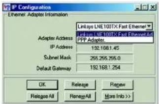
text_image
IP Configuration Ethernet Adapter Information Linksys LNE100TX Fast Ethernet Linksys LNE 100TX Fast Ethernet And FPP Adapter Adapter Address IP Address 192.168.1.45 Subnet Mask 255.255.255.0 Default Gateway 192.168.1.254 OK Release Review Relapse All Renew All More Info >>Figure E-1: IP Configuration Screen
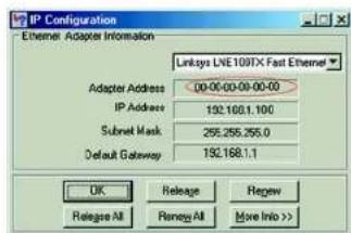
text_image
IP Configuration Ethernet Adapter Information Linksys LWE100TX Fast Ethernet Adapter Address 00:00-00:00-00 IP Address 192.168.1.100 Subset Mask 255.255.255.0 Default Gateway 192.168.1.1 OK Release Cancel Release All Remay All Move Info >>Figure E-2: MAC Address/Adapter Address
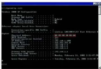
text_image
Terminal screenshot showing network configuration options for Windows 2008 IP configuration, including connection-specific DNS suffixes and primary/secondary server configurations.Figure E-3: MAC Address/Physical Address
Wireless-G Broadband Router with RangeBooster
- Write down the Physical Address as shown on your computer screen (Figure E-3); it is the MAC address for your Ethernet adapter. This appears as a series of numbers and letters.
The MAC address/Physical Address is what you will use for MAC address cloning or MAC filtering.
Note: The MAC address is also called the Physical Address.

The example in Figure E-3 shows the Ethernet adapter's IP address as 192.168.1.100. Your computer may show something different.
For the Router's Web-based Utility
For MAC filtering, enter the 12-digit MAC address in this format,XXXXXXXXXX, WITHOUT the hyphens. See Figure E-4. Or select a client from the Wireless Client List, Figure E-5.
For MAC address cloning, enter the 12-digit MAC address in the MAC Address fields provided, two digits per field. See Figure E-6.
For more information, refer to Chapter 6: Configuring the Wireless-G Broadband Router with RangeBooster.
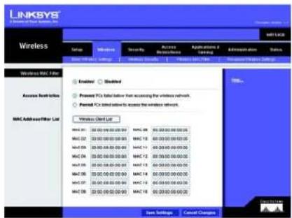
text_image
LINKSYS Wireless Networks OSI Network Security Access Application / Administration Status Wireless MAC Filter Encoder Modified Access Break-even Present PC's label below from accessing the wireless network. Named PC's label below to access the wireless network. Mac AddressFilter List Windows Open List MAC 01: 35.00.00.00.00.00 MAC 02: 35.00.00.00.00.00 MAC 03: 35.00.00.00.00.00 MAC 04: 35.00.00.00.00.00 MAC 05: 35.00.00.00.00.00 MAC 06: 35.00.00.00.00.00 MAC 07: 35.00.00.00.00.00 MAC 08: 35.00.00.00.00.00 Start Settings Cancel ChangesFigure E-4: MAC Address Filter List
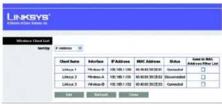
text_image
LINKSYS Connection to User List, Inc. Wireless Client List Sort by P Address Client Name Interface P Address MAC Address Status Care to MAC Address Filter List Linksys 1 \Windows-0 190.169.1.100 90.40.65.35.02:03 Connected □ Linksys 2 Windows-A 190.169.1.101 90.40.65.35.02:02 Disconnected □ Linksys 3 \Windows-B 190.169.1.102 90.40.65.35.02:03 Connected □ Add Ratech CrossFigure E-5: Wireless Client List
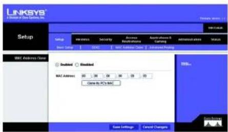
text_image
LINKSYS Setup to be Spings, Inc. Setup MAC Address Close MAC Address: 00 30 04 04 05 20 Close to PC's MAC Status OK/Cancel Changes Save Settings Cancel Changes Add to PC's MAC Add to PC's MAC Add to PC's MAC Add to PC's MAC Add to PC's MAC Add to PC's MAC Add to PC's MAC Add to PC's MAC Add to PC's MAC Add to PC's MAC Add to PC's MAC Add to PC's MAC Add to PC's MAC Add to PC's MAC Add to PC's MAC Add to PC's MAC Add to PC's MAC Add to Mac Add to Mac Add to Mac Add to Mac Add to Mac Add to Mac Add to Mac Add to Mac Add to Mac Add to Mac Add to Mac Add to Mac Add to Mac Add to Mac Add to Mac Add to Mac Add to Mac Add to Mac Add to Mac Add to Mac Add to Mac Add to Mac Add to Mac Add to Mac Add to Mac Add to MC Add to MC Add to MC Add to MC Add to MC Add to MC Add to MC Add to MC Add to MC Add to MC Add to MC Add to MC Add to MC Add to MC Add to MC Add to MC Add to MC Add to MC Add to MC Add to MC Add to MC Add to MC Add to MC Add to MC Add to MC Add to NCFigure E-6: MAC Address Cloning
Appendix E: Finding the MAC Address and IP Address for Your Ethernet Adapter For the Router's Web-based Utility
Wireless-G Broadband Router with RangeBooster

This glossary contains some basic networking terms you may come across when using this product. For more advanced terms, see the complete Linksys glossary at http://www.linksys.com/international/glossary.
Access Point - A device that allows wireless-equipped computers and other devices to communicate with a wired network. Also used to expand the range of a wireless network.
Ad-hoc - A group of wireless devices communicating directly with each other (peer-to-peer) without the use of an access point.
AES (Advanced Encryption Standard) - A security method that uses symmetric 128-bit block data encryption.
Bandwidth - The transmission capacity of a given device or network.
Bit - A binary digit.
Boot - To start a device and cause it to start executing instructions.
Broadband - An always-on, fast Internet connection.
Browser - An application program that provides a way to look at and interact with all the information on the World Wide Web.
Byte - A unit of data that is usually eight bits long
Cable Modem - A device that connects a computer to the cable television network, which in turn connects to the Internet.
Daisy Chain - A method used to connect devices in a series, one after the other.
DDNS (Dynamic Domain Name System) - Allows the hosting of a website, FTP server, or e-mail server with a fixed domain name (e.g., www.xyz.com) and a dynamic IP address.
Default Gateway - A device that forwards Internet traffic from your local area network.
DHCP (Dynamic Host Configuration Protocol) - A networking protocol that allows administrators to assign temporary IP addresses to network computers by "leasing" an IP address to a user for a limited amount of time, instead of assigning permanent IP addresses.
Wireless-G Broadband Router with RangeBooster
DMZ (Demilitarized Zone) - Removes the Router's firewall protection from one PC, allowing it to be "seen" from the Internet.
DNS (Domain Name Server) - The IP address of your ISP's server, which translates the names of websites into IP addresses.
Domain - A specific name for a network of computers.
Download - To receive a file transmitted over a network.
DSL (Digital Subscriber Line) - An always-on broadband connection over traditional phone lines.
Dynamic IP Address - A temporary IP address assigned by a DHCP server.
EAP (Extensible Authentication Protocol) - A general authentication protocol used to control network access. Many specific authentication methods work within this framework.
Encryption - Encoding data transmitted in a network.
Ethernet - IEEE standard network protocol that specifies how data is placed on and retrieved from a common transmission medium.
Firewall - A set of related programs located at a network gateway server that protects the resources of a network from users from other networks.
Firmware - The programming code that runs a networking device.
FTP (File Transfer Protocol) - A protocol used to transfer files over a TCP/IP network.
Full Duplex - The ability of a networking device to receive and transmit data simultaneously.
Gateway - A device that interconnects networks with different, incompatible communications protocols.
Half Duplex - Data transmission that can occur in two directions over a single line, but only one direction at a time.
HTTP (HyperText Transport Protocol) - The communications protocol used to connect to servers on the World Wide Web.
Infrastructure - A wireless network that is bridged to a wired network via an access point.
IP (Internet Protocol) - A protocol used to send data over a network.
Wireless-G Broadband Router with RangeBooster
IP Address - The address used to identify a computer or device on a network.
IPCONFIG - A Windows 2000 and XP utility that displays the IP address for a particular networking device.
IPSec (Internet Protocol Security) - A VPN protocol used to implement secure exchange of packets at the IP layer.
ISP (Internet Service Provider) - A company that provides access to the Internet.
LAN - The computers and networking products that make up your local network.
MAC (Media Access Control) Address - The unique address that a manufacturer assigns to each networking device.
Mbps (MegaBits Per Second) - One million bits per second; a unit of measurement for data transmission.
NAT (Network Address Translation) - NAT technology translates IP addresses of a local area network to a different IP address for the Internet.
Network - A series of computers or devices connected for the purpose of data sharing, storage, and/or transmission between users.
Packet - A unit of data sent over a network.
Passphrase - Used much like a password, a passphrase simplifies the WEP encryption process by automatically generating the WEP encryption keys for Linksys products.
Ping (Packet INternet Groper) - An Internet utility used to determine whether a particular IP address is online.
POP3 (Post Office Protocol 3) - A standard mail server commonly used on the Internet.
Port - The connection point on a computer or networking device used for plugging in cables or adapters.
Power over Ethernet (PoE) - A technology enabling an Ethernet network cable to deliver both data and power.
PPPoE (Point to Point Protocol over Ethernet) - A type of broadband connection that provides authentication (username and password) in addition to data transport.
PPTP (Point-to-Point Tunneling Protocol) - A VPN protocol that allows the Point to Point Protocol (PPP) to be tunneled through an IP network. This protocol is also used as a type of broadband connection in Europe.
RADIUS (Remote Authentication Dial-In User Service) - A protocol that uses an authentication server to control network access.
Wireless-G Broadband Router with RangeBooster
RJ-45 (Registered Jack-45) - An Ethernet connector that holds up to eight wires.
Roaming - The ability to take a wireless device from one access point's range to another without losing the connection.
Router - A networking device that connects multiple networks together.
Server - Any computer whose function in a network is to provide user access to files, printing, communications, and other services.
SMTP (Simple Mail Transfer Protocol) - The standard e-mail protocol on the Internet.
SNMP (Simple Network Management Protocol) - A widely used network monitoring and control protocol.
SPI (Stateful Packet Inspection) Firewall - A technology that inspects incoming packets of information before allowing them to enter the network.
SSID (Service Set Identifier) - Your wireless network's name.
Static IP Address - A fixed address assigned to a computer or device that is connected to a network.
Static Routing - Forwarding data in a network via a fixed path.
Subnet Mask - An address code that determines the size of the network.
Switch - 1. A data switch that connects computing devices to host computers, allowing a large number of devices to share a limited number of ports. 2. A device for making, breaking, or changing the connections in an electrical circuit.
TCP (Transmission Control Protocol) - A network protocol for transmitting data that requires acknowledgement from the recipient of data sent.
TCP/IP (Transmission Control Protocol/Internet Protocol) - A set of instructions PCs use to communicate over a network.
Telnet - A user command and TCP/IP protocol used for accessing remote PCs.
TFTP (Trivial File Transfer Protocol) - A version of the TCP/IP FTP protocol that has no directory or password capability.
Throughput - The amount of data moved successfully from one node to another in a given time period.
Wireless-G Broadband Router with RangeBooster
TKIP (Temporal Key Integrity Protocol) - a wireless encryption protocol that provides dynamic encryption keys for each packet transmitted.
Topology - The physical layout of a network.
TX Rate - Transmission Rate.
Upgrade - To replace existing software or firmware with a newer version.
Upload - To transmit a file over a network.
URL (Uniform Resource Locator) - The address of a file located on the Internet.
VPN (Virtual Private Network) - A security measure to protect data as it leaves one network and goes to another over the Internet.
WAN (Wide Area Network)- The Internet.
WEP (Wired Equivalent Privacy) - A method of encrypting network data transmitted on a wireless network for greater security.
WLAN (Wireless Local Area Network) - A group of computers and associated devices that communicate with each other wirelessly.
WPA (Wi-Fi Protected Access) - a wireless security protocol using TKIP (Temporal Key Integrity Protocol) encryption, which can be used in conjunction with a RADIUS server.
Wireless-G Broadband Router with RangeBooster

Model WRT54GR
Standards IEEE 802.3, IEEE 802.3u, IEEE 802.11g, IEEE 802.11b
Channels 11 Channels (Most of North, Central, and Southern America) 13 Channels (Most of Europe and Asia)
Ports Internet: One 10/100 RJ-45 Port LAN: Four 10/100 RJ-45 Switched Ports One Power Port
Buttons Reset
LEDs Power, DMZ, Wireless, Ethernet (1-4), Internet
Peak Gain of the Antenna 2 dBi
Transmitted Power 802.11g: 17 ± 1 dBm (Typical) 802.11b: 17 ± 1 dBm (Typical)
Receive Sensitivity 11Mbps @ -89dBm (Typical) 54Mbps @ -78dBm (Typical)
Power External, 12V DC, 500mA
Security Features Double Firewalls (NAT and SPI), Internet Policy, Wireless Filters, Wireless Security - WEP and WPA Encryption
Dimensions (W x H x D) 140 x 130 x 170 mm
Unit Weight 0.3 kg
Wireless-G Broadband Router with RangeBooster
Power External, 12V DC, 500mA
Certifications FCC, Wi-Fi, CE
Operating Temp. 0°C to 40°C (32°F to 104°F)
Storage Temp. -20°C to 70°C (-4°F to 158°F)
Operating Humidity 10% to 85%, Non-Condensing
Storage Humidity 5% to 90%, Non-Condensing
Wireless-G Broadband Router with RangeBooster

natural_image
Collection of black and white geometric symbols including stars, circles, and squares (no text or labels)Linksys warrants to You that, for a period of three years (the "Warranty Period"), your Linksys Product will be substantially free of defects in materials and workmanship under normal use. Your exclusive remedy and Linksys' entire liability under this warranty will be for Linksys at its option to repair or replace the Product or refund Your purchase price less any rebates. This limited warranty extends only to the original purchaser.
If the Product proves defective during the Warranty Period call Linksys Technical Support in order to obtain a Return Authorization Number, if applicable. BE SURE TO HAVE YOUR PROOF OF PURCHASE ON HAND WHEN CALLING. If You are requested to return the Product, mark the Return Authorization Number clearly on the outside of the package and include a copy of your original proof of purchase. RETURN REQUESTS CANNOT BE PROCESSED WITHOUT PROOF OF PURCHASE. You are responsible for shipping defective Products to Linksys. Linksys pays for UPS Ground shipping from Linksys back to You only. Customers located outside of the United States of America and Canada are responsible for all shipping and handling charges.
ALL IMPLIED WARRANTIES AND CONDITIONS OF MERCHANTABILITY OR FITNESS FOR A PARTICULAR PURPOSE ARE LIMITED TO THE DURATION OF THE WARRANTY PERIOD. ALL OTHER EXPRESS OR IMPLIED CONDITIONS, REPRESENTATIONS AND WARRANTIES, INCLUDING ANY IMPLIED WARRANTY OF NON-INFRINGEMENT, ARE DISCLAIMED. Some jurisdictions do not allow limitations on how long an implied warranty lasts, so the above limitation may not apply to You. This warranty gives You specific legal rights, and You may also have other rights which vary by jurisdiction.
This warranty does not apply if the Product (a) has been altered, except by Linksys, (b) has not been installed, operated, repaired, or maintained in accordance with instructions supplied by Linksys, or (c) has been subjected to abnormal physical or electrical stress, misuse, negligence, or accident. In addition, due to the continual development of new techniques for intruding upon and attacking networks, Linksys does not warrant that the Product will be free of vulnerability to intrusion or attack.
TO THE EXTENT NOT PROHIBITED BY LAW, IN NO EVENT WILL LINKSYS BE LIABLE FOR ANY LOST DATA, REVENUE OR PROFIT, OR FOR SPECIAL, INDIRECT, CONSEQUENTIAL, INCIDENTAL OR PUNITIVE DAMAGES, REGARDLESS OF THE THEORY OF LIABILITY (INCLUDING NEGLIGENCE), ARISING OUT OF OR RELATED TO THE USE OF OR INABILITY TO USE THE PRODUCT (INCLUDING ANY SOFTWARE), EVEN IF LINKSYS HAS BEEN ADVISED OF THE POSSIBILITY OF SUCH DAMAGES. IN NO EVENT WILL LINKSYS' LIABILITY EXCEED THE AMOUNT PAID BY YOU FOR THE PRODUCT. The foregoing limitations will apply even if any warranty or remedy provided under this Agreement fails of its essential purpose. Some jurisdictions do not allow the exclusion or limitation of incidental or consequential damages, so the above limitation or exclusion may not apply to You.
This Warranty is valid and may be processed only in the country of purchase.
Please direct all inquiries to: Linksys, P.O. Box 18558, Irvine, CA 92623.
Wireless-G Broadband Router with RangeBooster

natural_image
Collection of black and white geometric symbols including stars, circles, and triangles (no text or labels)FCC Statement
This product has been tested and complies with the specifications for a Class B digital device, pursuant to Part 15 of the FCC Rules. These limits are designed to provide reasonable protection against harmful interference in a residential installation. This equipment generates, uses, and can radiate radio frequency energy and, if not installed and used according to the instructions, may cause harmful interference to radio communications. However, there is no guarantee that interference will not occur in a particular installation. If this equipment does cause harmful interference to radio or television reception, which is found by turning the equipment off and on, the user is encouraged to try to correct the interference by one or more of the following measures:
• Reorient or relocate the receiving antenna
- Increase the separation between the equipment or devices
- Connect the equipment to an outlet other than the receiver's
- Consult a dealer or an experienced radio/TV technician for assistance
FCC Radiation Exposure Statement
This equipment complies with FCC radiation exposure limits set forth for an uncontrolled environment. This equipment should be installed and operated with minimum distance 20cm between the radiator and your body.
Safety Notices
Caution: To reduce the risk of fire, use only No.26 AWG or larger telecommunication line cord.
Do not use this product near water, for example, in a wet basement or near a swimming pool.
Avoid using this product during an electrical storm. There may be a remote risk of electric shock from lightning.
Industry Canada (Canada)
This device complies with Canadian ICES-003 and RSS210 rules.
Wireless-G Broadband Router with RangeBooster
Compliance Information for 2.4-GHz Wireless Products Relevant to the EU and Other Countries Following the EU Directive 1999/5/EC (R&TTE Directive)
Declaration of Conformity with Regard to the EU Directive 1999/5/EC (R&TTE Directive)
| Česky [Czech]: | Toto zařízení je v soulada se základními požadavky a ostatními odpovídajícími ustanoveními Šměrnice 1999/5/EC. |
| Dansk [Danish]: | Dette udstyr er i overensstemmelse med de væsentlige krav og andre relevante bestemmelser i Direktiv 1999/5/EF. |
| Deutsch [German]: | Dieses Gerät entspricht den grundlegenden Anforderungen und den weiteren entsprechenden Vorgaben der Richtlinie 1999/5/EU. |
| Eesti [Estonian]: | See seade vastab direktivi 1999/5/EÚ olulistele nõutele ja teistele asjakohastele sätetele. |
| English: | This equipment is in compliance with the essential requirements and other relevant provisions of Directive 1999/5/EC. |
| Español [Spanish]: | Este equipo cumple con los requisitos esenciales asi como con otras disposiciones de la Directiva 1999/5/CE. |
| Ešlýnučki [Greek]: | Anotć o ešorčlanjíc čevis na osmůjóppoosn je tis ovensiðes; aπαιησεις και ύλες σχετικές διατάξης της Οδηγίας 1999/5/EC. |
| Français [French]: | Cet appareil est conforme aux exigences essentielles et aux autres dispositions pertinentes de la Directive 1999/5/EC. |
| Íslenska [Icelandic]: | Petta takí er samkvæmt grunkrótímog og ðbrum viðeigandi ákvæðum Tilskipunar 1999/5/EC. |
| Italiano [Italian]: | Questo appara to ć conforme ai requisiti essenziali ed agli altri principi sanciti dalla Direttiva 1999/5/CE. |
| Latviski [Latvian]: | Št iekártta atblist Direktīvas 1999/5/EK būtiskajām prasībām un citiem ar to saistitajiem noteikumiem. |
| Lietuvių [Lithuanian]: | Šis jenginys tenkina 1999/5/EB Direktyvos esminius reikalavimus ir kitas šios direktyvos nuostatas. |
| Nederlands [Dutch]: | Dit apparaat voldoet aan de essentiele eisen en andere van toepassing zijnde bepalingen van de Richtlijna 1999/5/EC. |
| Malti [Maltese]: | Dan l-apparat huva konformi mal-htigiet essenzjali u l-provedimenti l-ohra rilevanti tad-Direttiva 1999/5/EC. |
| Margyar [Hungarian]: | Ez a készülék teljesítí az alapvető követelményeket és más 1999/5/EK irányelvben meghatározott vonatkozó rendelkezéseket. |
| Norsk [Norwegian]: | Dette utstyret er i samsvar med de grunnleggende krav og andre relevante bestemmelser i EU-direktiv 1999/5/EF. |
| Polski [Polish]: | Urządzenie jest zgodne z ogólnyni wymaganiami oraz szczególnymi warunkami okresłonymi Dyrektywa UE: 1999/5/EC. |
| Português [Portuguese]: | Este equipamento está em conformidade com os requisitos essenciais e outras provisões relevantes da Directiva 1999/5/EC. |
| Románá [Romanian]: | Acest echipament este in conformitate cu cerintele esentiale si cu alte prevederi relevante ale Direcítivei 1999/5/EC. |
| Slovensko [Slovenian]: | Ta naprava je skladna z bistveními zahtevami in ostalimi relevantními pogoji Direktive 1999/5/EC. |
| Slovensky [Slovak]: | Toto zariadenie je v zhode so základnými požiadavkami a inými prislašnými nariadeniami direktiv: 1999/5/EC. |
| Suomi [Finnish]: | Tämä laite täyttää direktiivin 1999/5/EY olenaiset vaatimukset ja on siinä asetettujen muiden laitetta koskevien mälärlysten mukainen. |
| Svenska [Swedish]: | Denna utrustning är i överensstämmelse med de väsentliga kraven och andra relevanta bestämmelser i Direktiv 1999/5/EC. |
Wireless-G Broadband Router with RangeBooster
NOTE: For all products, the Declaration of Conformity is available through one or more of these options:
- A pdf file is included on the product's CD.
- A print copy is included with the product.
- A pdf file is available on the product's webpage. Visit www.linksys.com/international and select your country or region. Then select your product.
If you need any other technical documentation, see the “Technical Documents on www.linksys.com/international” section, as shown later in this appendix.
The following standards were applied during the assessment of the product against the requirements of the Directive 1999/5/EC:
• Radio: EN 300 328
• EMC: EN 301 489-1, EN 301 489-17
• Safety: EN 60950 and either EN 50385 or EN 50371
CE Marking
For the Linksys Wireless-B and Wireless-G products, the following CE mark, notified body number (where applicable), and class 2 Identifier are added to the equipment.
CE 0560 ⚠
or or
CE 0678 Ⓙ
CE!
Check the CE label on the product to find out which notified body was involved during the assessment.
National Restrictions
This product may be used in all EU countries (and other countries following the EU directive 1999/5/EC) without any limitation except for the countries mentioned below:
Wireless-G Broadband Router with RangeBooster
Belgium
The Belgian Institute for Postal Services and Telecommunications (BIPT) must be notified of any outdoor wireless link having a range exceeding 300 meters. Please check http://www.bipt.be for more details.
In case the product is used outdoors, the output power is restricted in some parts of the band. See Table 1 or check http://www.arcep.fr/ for more details.
Table 1: Applicable Power Levels in France
| Location Frequency Range (MHz) Power (EIRP) | ||
| Indoor (No restrictions) 2400-2483.5 100 mW (20 dBm) | ||
| Outdoor 2400-2454 | 2454-2483.5 | 100 mW (20 dBm)10 mW (10 dBm) |
Italy
This product meets the National Radio Interface and the requirements specified in the National Frequency Allocation Table for Italy. Unless operating within the boundaries of the owner's property, the use of this 2.4 GHz Wireless LAN product requires a 'general authorization'. Please check with http://www.comunicazioni.it/it/ for more details.
Wireless-G Broadband Router with RangeBooster
Product Usage Restrictions
This product is designed for indoor usage only. Outdoor usage is not recommended.
This product is designed for use with the standard, integral or dedicated (external) antenna(s) that is/are shipped together with the equipment. However, some applications may require the antenna(s), if removable, to be separated from the product and installed remotely from the device by using extension cables. For these applications, Linksys offers an R-SMA extension cable (AC9SMA) and an R-TNC extension cable (AC9TNC). Both of these cables are 9 meters long and have a cable loss (attenuation) of 5 dB. To compensate for the attenuation, Linksys also offers higher gain antennas, the HGA7S (with R-SMA connector) and HGA7T (with R-TNC connector). These antennas have a gain of 7 dBI and may only be used with either the R-SMA or R-TNC extension cable.
Combinations of extension cables and antennas resulting in a radiated power level exceeding 100 mW EIRP are illegal.
Power Output of Your Device
To comply with your country's regulations, you may have to change the power output of your wireless device. Proceed to the appropriate section for your device.
NOTE: The power output setting may not be available on all wireless products. For more information, refer to the documentation on your product's CD or http://www.linksys.com/international.
Wireless Adapters
Wireless adapters have the power output set to 100% by default. Maximum power output on each adapter does not exceed 20 dBm (100 mW); it is generally 18 dBm (64 mW) or below. If you need to alter your wireless adapter's power output, follow the appropriate instructions for your computer's Windows operating system:
Windows XP
- Double-click the Wireless icon in your desktop's system tray.
- Open the Wireless Network Connection window.
- Click the Properties button.
- Select the General tab, and click the Configure button.
- In the Properties window, click the Advanced tab.
- Select Power Output.
- From the pull-down menu on the right, select the wireless adapter's power output percentage.
Wireless-G Broadband Router with RangeBooster
Windows 2000
- Open the Control Panel.
- Double-click Network and Dial-Up Connections.
- Select your current wireless connection, and select Properties.
- From the Properties screen, click the Configure button.
- Click the Advanced tab, and select Power Output.
- From the pull-down menu on the right, select the wireless adapter's power setting.
If your computer is running Windows Millennium or 98, then refer to Windows Help for instructions on how to access the advanced settings of a network adapter.
Wireless Access Points, Routers, or Other Wireless Products
If you have a wireless access point, router or other wireless product, use its Web-based Utility to configure its power output setting (refer to the product's documentation for more information).
Technical Documents on www.linksys.com/international
Follow these steps to access technical documents:
- Enter http://www.linksys.com/international in your web browser.
- Select the country or region in which you live.
- Click the Products tab.
- Select the appropriate product category.
- Select the product sub-category, if necessary.
- Select the product.
- Select the type of documentation you want from the More Information section. The document will open in PDF format if you have Adobe Acrobat installed on your computer.
NOTE: If you have questions regarding the compliance of these products or you cannot find the information you need, please contact your local sales office or visit http://www.linksys.com/international for more details.
Wireless-G Broadband Router with RangeBooster
User Information for Consumer Products Covered by EU Directive 2002/96/EC on Waste Electric and Electronic Equipment (WEEE)
This document contains important information for users with regards to the proper disposal and recycling of Linksys products. Consumers are required to comply with this notice for all electronic products bearing the following symbol:
English
Environmental Information for Customers in the European Union
European Directive 2002/96/EC requires that the equipment bearing this symbol on the product and/or its packaging must not be disposed of with unsorted municipal waste. The symbol indicates that this product should be disposed of separately from regular household waste streams. It is your responsibility to dispose of this and other electric and electronic equipment via designated collection facilities appointed by the government or local authorities. Correct disposal and recycling will help prevent potential negative consequences to the environment and human health. For more detailed information about the disposal of your old equipment, please contact your local authorities, waste disposal service, or the shop where you purchased the product.
Ceština/Czech
natural_image
Pure electrical circuit lines without any symbolsWireless-G Broadband Router with RangeBooster
Dansk/Danish
Miljøinformation for kunder i EU
Appendix I: Regulatory Information
Español/Spanish
Wireless-G Broadband Router with RangeBooster
Français/French
Appendix I: Regulatory Information
Lietuvškai/Lithuanian
Aplinkosaugos informacija, skirta Europos Sajungos vartotojams
Wireless-G Broadband Router with RangeBooster
Nederlands/Dutch
Appendix I: Regulatory Information
Wireless-G Broadband Router with RangeBooster
Suomi/Finnish
Wireless-G Broadband Router with RangeBooster


Need to contact Linksys?
Visit us online for information on the latest products and updates to your existing products at:
http://www.linksys.com/international
If you experience problems with any Linksys product, you can e-mail us at:
| In Europe E-mail Address | |
| Austria support.at@linksys.com | |
| Belgium support.be@linksys.com | |
| Denmark support.dk@linksys.com | |
| France support.fr@linksys.com | |
| Germany support.de@linksys.com | |
| Italy support.it@linksys.com | |
| Netherlands support.nl@linksys.com | |
| Norway support.no@linksys.com | |
| Portugal support.pt@linksys.com | |
| Spain support.es@linksys.com | |
| Sweden support.se@linksys.com | |
| Switzerland support.ch@linksys.com | |
| United Kingdom & Ireland support.uk@linksys.com |
| Outside of Europe E-mail | Address |
| Asia Pacific | asiasupport@linksys.com (English only) |
| Latin America | support.portuguese@linksys.com or support.spanish@linksys.com |
| Middle East & Africa | support.mea@linksys.com (English only) |
| U.S. and Canada | support@linksys.com |
LINKSYS®
A Division of Cisco Systems, Inc.

natural_image
Exterior view of a white wireless router with two black antennas and a blue L908YS brand logo (no readable text beyond branding)2,4 GHz 802.11g
Wireless-G
Benutzerhandbuch
WIRELESS
text_image
Collection of symbolic and stylized symbols in black, white, and red, including stars, circles, and triangles with standard line notation.Rückseite
text_image
Wireless-G BroadBond Roster with Range Boostertext_image
Collection of black-and-white symbols including stars, circles, and triangles with standard line notationnatural_image
Front view of a network switch with Ethernet port and power indicator (no text or symbols on main components)natural_image
Front view of a network switch with ports and a blue cable (no visible text or symbols)natural_image
Close-up of a network switch device showing ports labeled 1, 2, 3, and 4, with a cable inserted (no readable text or symbols beyond labels)text_image
Collection of various symbols and colors, including stars, squares, circles, and asterisks with corresponding star-like and circle-like shapes.Übersicht

text_image
LINKSYS A Software Setup, Inc. SET vs. TCP Setup Setup Network Settings Internal Connection Type Optional Settings (Required by service: Internal Service Providers) Network Settings Router IP BNCIP Server Setting Time Settings View Jaze Automatic Configuration - DHCP Host name: Domain Name: WU: Auto Size P Address: 162 168 1 Subnet Mask: 290 295 295.0 DHCP Server: Enabled Enabled Data DHCP Start A Address: 162 168 1 100 Minimum Number of Users: 16 P Address Range: 162 1681 1680 - 168 Client-Less Time: 9 minutes (3 minutes are day) State DNS 1: 0 0 0 0 State DNS 2: 0 0 0 0 State DNS 3: 0 0 0 0 PING: 9 0 0 0 Automatic adjust clock for daylight saving charges. Save Settings Cancel Changes| Internet Connection Type | Static IP | |||
| Internet IP Address: | 0 | 0 | 0 | |
| Subnet Music: | 0 | 0 | 0 | |
| Default Gateway: | 0 | 0 | 0 | |
| DNS 1: | 0 | 0 | 0 | |
| DNS 2: | 0 | 0 | 0 | |
| DNS 3: | 0 | 0 | 0 | |
text_image
Internet Connection Type PPPoE Username: Password Connect on Demand: Max: Idle Time 15 Minutes. Keep Alive: Redial Period 30 Seconds.text_image
Internet Connection Type PPTP Server IP Address: 0 0 0 0 Subset Music: 0 0 0 0 Default Gateway: 0 0 0 0 Username: Password: Connect on Demand: Max Idle Time 15 Minutes. Keep Alive: Redial Period 30 Seconds.text_image
Internet Connection Type Heart Best Signal Server IP Address: 0 .0 .0 .0 Username: Password:text_image
Optional Settings (required by some Internet Service Providers) Host Name: Domain Name: MTU: Auto Size: 1500text_image
DHCP Server Setting DHCP Server: Enabled Disabled Static DHCP Start IP Address: 192.168.1.100 Maximum Number of Users: 50 IP Address Range: 192.168.1.100 - 149 Client Lease Time: 0 minutes (0 means one day) Static DNS 1: 0 0 0 0 Static DNS 2: 0 0 0 0 Static DNS 3: 0 0 0 0 VINS: 0 0 0 0text_image
LINKSYS® A Million of Data Systems, Inc. Static DHCP Client List DHCP Client Type Average File P To Data MAC Husband 162 160.0 1 F 30:00:00:00:00:00 162 160.0 1 F 30:00:00:00:00:00 162 160.0 1 F 30:00:00:00:00:00 162 160.0 1 F 30:00:00:00:00:00 162 180.0 1 F 30:00:00:00:00:00 162 180.0 1 F 30:00:00:00:00:00 162 180.0 1 F 30:00:00:00:00:00 162 180.0 1 FAbbildung 5-11: „DHCP Server Settings“ (DHCP-Servereinstellungen)
text_image
LINKSYS LINKSYS Client Table Send by: IP Address Client Name Interface IP Address MISC Address See to Start LINKSYS Client List Link1 1 Left 102/1681.530 03/04/09:30 03:03 Link2 2 Verticals A 102/1681.530 03/04/09:30 03:03 Link3 3 Verticals B 102/1681.530 03/04/09:30 03:03 Link4 4 Verticals C 102/1681.530 03/04/09:30 03:03 TCP Internet Access...Abbildung 5-12: „DHCP Client Table“ (DHCP-Client-Tabelle):
text_image
LINKSYS® A Division of Our Systems, Inc. Setup DNS DNS Service DynVIG.org Username: Password: Host Name: Internet IP Address: 102.1681.100 Status: Connect Save Settings Cancel Changes SNPs... Goss Servicestext_image
LINKSYS® A Series of Data Systems, LLC Setup Setup Name: 1000000000000000000000000000000000000000000000000000000000000000000000000000 E:\Users\SDMS Service T20 address E-mail Address: T20-Password: Domain Name: Email P Address: 122/88.1.152 Status Connect Save Settings Cancel Changes OK Cancel Options OK Cancel Settings Cancel Changestext_image
LINKSYS® A Division of Data Systems, Inc. Setup MAC Address Close Enabled Enabled MAC Address 00 00 04 08 00 09 Close by PC's MAC Save Settings Cancel Changes MAC Address Close MAC Address Close MAC Address Close MAC Address Close MAC Address Close MAC Address Close MAC Address Close MAC Address Close MAC Address Close MAC Address Close MAC Address Close MAC Address Close MAC Address Close MAC Address Close MAC Address Close MAC Address Close MAC Address Close MAC Address Close MAC Address Close MAC Address Close MAC Address Close MAC Address Close MAC Address Close MAC Address Close MAC Address Close MAC Address Closedtext_image
LINKSYS® A Division of Data Systems, INC. Formwork Manager 1.1 Setup METHUATE Setup Wireless Security Access Instructions Applications & Learning Administration Status Basic Setup DNTC NAV Address Client Advanced Routing Advanced Routing NAT Enabled Blocked Dynamic Routing (DIP) Enabled Blocked Static Routing Route Entries: 10 Delete Tree Entry Enter Route Name: Destination LAN P: 6 0 0 0 Subset Mask: 6 0 0 0 Gateway: 6 0 0 0 Interface: LAN & Wireless Show Routing Table Save Settings Cancel Changes Help... Data Surveytext_image
LINKSYS® A Division of Cisco Systems, Inc. Routing Table Destination LAN IP Submit Mask Gateway Interface 10:10:10.100 255.255.255.0 10:10:10.1 Internet (WWW) 192.168.1.100 255.255.255.0 192.168.1.1 LAN & Wireless Refresh Closetext_image
LINKSYS A Division of Data Systems, Inc. Forward Version 1.1 Wireless Settings Windows Security Access Settings Application & Settings Administration Status Basic Wireless Settings Wireless Network Bus: Mixed Network Name (SSD) Switch Channel 8: 2.437GHz SSD Broadcast Enabled Enabled Basic Wireless Settings Cancel Changes Hill... Save Settings Cancel Changestext_image
LINKSYS® Fileset at Data System, Inc. Windows Server 1.0 MNT-2008 Wireless Setup Wireless Security Security Mode: HCP Options: 40/164.6k (10 Hz dB(A)) Peripherals: Goggles Key 1: Key 2: Key 3: Key 4: Tx Key: 1 Send Settings Cancel Changes WIRE... Send Service OKtext_image
LINKSYS A Security of Blue Systems, Inc. Wireless Setup Wireless Security Access Accessories Applications & Carting Accession Status Basic Per Filter Settings Inference Security Per Filter MAC Filter Advanced Per Filter Settings Wireless Security Security Book: NPA-Personal Exception: TCP Accession: Key Personal: 3699 seconds Save Settings Cancel Changes Help... Send OptionsAbbildung 5-21: Registerkarte „Wireless“ – „Wireless Security (WPA-Personal)“ (Wireless-Sicherheit (WPA-Personal))

text_image
LINKSYS A Division of Cloud Services, Inc. Wireless SETUP Wireless Security Access Applications & Listing Administration Share New Wireless Settings Preferred Security Preferred MAC Filter Advanced/Request Settings Wireless Security Security Mode: PSX3 Encryption: AFS Peripherals: Key Personal: 2600 seconds Size Settings Cancel Changes Mills... Save by: http://www. links/ Save by: http://www. links/ Save by: http://www. links/ Save by: http://www. links/ Save by: http://www. links/ Save by: http://www. links/ Save by: http://www. links/ Save by: http://www. links/ Save by: http://www. links/ Save by: http://www. links/ Save by: http://www. links/ Save by: http://www. links/ Move Settings Cancel ChangesAbbildung 5-22: Registerkarte „Wireless“ – „Wireless Security (PSK2)“ (Wireless-Sicherheit (PSK2))
text_image
LINKSYS® A Division of Star Systems Inc. Wireless Settings Security Access Applications & Administration Status Next Update Settings Next Update Settings New Security New Security Access Access Wireless Security Security Mode: PSX2-Mixed Encryption: mRNA-Personal (TIP) or PSX2 (ACS) Passion Mode: KeyRenewalk 3000 seconds New Settings Current Changes Edit... Save Settings Cancel ChangesAbbildung 5-23: Registerkarte „Wireless“ – „Wireless Security (PSK2-Mixed)“ (Wireless-Sicherheit (PSK2-Mixed))
text_image
LINKSYS A Division of Data Systems, Inc. Wireless Setup Wireless Security Access Instructions Applications & Settings Administration Status Send Wireless Settings Information Security Wireless Security Security Work: WAV-Extruder Networks USB HADUS Server: 3 9 8 9 HADUS Port: 1012 Shared Secret: Key Reserved: 3500 seconds Save Settings Cancel Changes Win... Carry OptionsAbbildung 5-24: Registerkarte „Wireless“ - „Wireless Security (WPA Enterprise)“ (Wireless-Sicherheit (WPA Enterprise))
text_image
LINKSYS A Division of Data Systems, Inc. Wireless Wireless Security Security Value: PSCHWALCKS Resolution: 480 RADIUS Server: 0 5 9 9 RADIUS Full: 1912 Shared Secret: Key Refresh: 3600 seconds Save Settings Cancel Changes Win... Save Security AAbbildung 5-25: Registerkarte „Wireless“ – „Wireless Security (PSK2 + RADIUS)“ (Wireless-Sicherheit (PSK2 + RADIUS))
text_image
LINKSYS A Million of Data Systems, Inc. Wireless Setup Wireless Security Access Instructions Applications & Settings Internalization Value Basic Wireless Settings Wireless Security Fixed Anti-Filter Advanced Wireless Settings Wireless Security Security Mode: RADIUS RADIUS Rate: 9 9 3 8 RADIUS Rate: 0/3 Shared Secret: Decryption: 16 / 144-bit (15 key rights) Peripherals: Generate Key1: Key2: Key3: Key4: TX key: 1 Size Settings Cancel Changes Data FromAbbildung 5-26: Registerkarte „Wireless“ – „Wireless Security (RADIUS)“ (Wireless-Sicherheit (RADIUS))
text_image
LINKSYS® A Division Of Data Systems, Inc. Wireless Client List Sort by IP Address Client Name Interface IP Address MAC Address Status Save to MAC Address Filter List Linksys 1 Wireless-0 192.168.1.100 00:40:05:35CE:61 Connected □ Linksys 2 Wireless-A 192.168.1.100 00:40:05:35CE:62 Disconnected □ Linksys 3 Wireless-B 192.168.1.100 00:40:05:35CE:63 Connected □ Auto Ratebox Cleantext_image
LINKSYS® A Division of Data Systems, Inc. Security Setup Windows Security Access Application & Administration Status Formalt SP/Formal Protection Enabled Enabled Microsoft Office File Anonymous Internet Requests File MultisEd File Internal NAT Redirection File ENE Short 135 Web Site Java Java ActiveX Cookies Save Settings Cancel Changes Help... Save Settings Cancel Changestext_image
LINKSYS A Division of Data System, Inc. Security Group Wireless Security Access Install actions Applications & Listing Administration Order Formal VRSPaththrough UFS Paththrough P500 Paththrough L310 Paththrough PPT0 Paththrough Enabled Enabled Enabled Enabled Enabled Help... Save Settings Cancel Changes Data Securitytext_image
LINKSYS 2.1000 of Cai Systems, Inc. Summary No. Policy Name Access Days Time Enabled 1 Home Deny Everyday 24 Hours Delete 2 Dennis Allow Sun, Mon, Tue, Wed, Thu, Fri, Sat 12:00 - 20:00 Delete 3 Children Allow Tue, Wed 09:00 - 13:00 Delete 4 --- --- --- --- --- 5 --- --- --- --- --- 6 --- --- --- --- --- 7 --- --- --- --- --- 8 --- --- --- --- --- 9 --- --- --- --- --- 10 --- --- --- --- --- Join Settings Cancel Changes Closetext_image
LINKSYS A Division of Data Systems, Inc. List of FCS MAC Address 01 00:00:00:00:00:00 06 00:00:00:00:00:00 02 00:00:00:00:00:00 07 00:00:00:00:00:00 03 00:00:00:00:00:00 08 00:00:00:00:00:00 04 00:00:00:00:00:00 09 00:00:00:00:00:00 05 00:00:00:00:00:00 10 00:00:00:00:00:00 IP Address 01 192 168.1.9 04 192 168.1.9 02 192 168.1.9 05 192 168.1.9 03 192 168.1.9 06 192 168.1.9 IP Address Range 01 192.168.1.9 - 33 192.168.1.9 - 8 02 192.168.1.9 - 34 192.168.1.9 - 8 Scan Settings Cancel Changes Closetext_image
LINKSYS A Division at Data System, Inc. Forens, Version 1.4 Applications & Gaming Set up Identities Security Access Restructures Applications & Gaming Admitted status Status Single Start Forwarding Start Range Forwarding Start Range Targeting SAG Part Range Triggering Application Name Triggered Range Forwarded Range Involved □ □ □ □ □ □ □ □ □ □ □ □ □ □ □ □ □ □ Save Settings Cancel Changes Send Optionstext_image
LINKSYS® A Division of Data Systems, Inc. Applications & Gaming HRT1236 Setup Wireless Security Access Receivables Applications & Gaming Administration Status Single Port Forwarding Port Range Forwarding Port Range Trigging D42 D42 Involved Stimulated Source P Address: Jny P Address Destination: P Address: 102, 109, 1, 3 MAC Address: Save Settings Cancel Changes Index Data Resourcestext_image
LINKSYS® A Wizard of Data Systems, Inc. Administration Setup Password Security Access Default Applications & Settings Administration Status Management Web Access Provider Password: Provider To Control: Web Access Accessibility Access: Accessibility Access No Accessibility Provider Management: Provider Management: Accessibility Access: Remote Diagnosis: Advanced Remote IP Address: Remote Management Port: Backup Configurations Remote Configurations Backup and Settings UPs2 Enabled Enabled Enabled User to Configur... Enabled User to Doicate Enabled Access... Enabled Enabled Enabled Cancel Changes Save Settings Cancel Changes WIN...text_image
LINKSYS Management Log Security Access Access to Access Application & Canning Administer Status Log Enabled Enabled LogPower F Address: 192.166.1.9 View Log Save Settings Cancel Changestext_image
LINKKEYS® A Division of Data Systems, Inc. Log Type Incoming Log Source IP Address 10.1910.130 Destination Port Number 36 Save the Log Refreshed Closetext_image
LINKSYS® A Division of Clear System, Inc. Administration Group Machine Security Access Instructions Applications & Settings Administration Status Management Log Diagnostics Factory Details Forward Upgrade Diagnostics Ping Test IP or URL Address: Packet Size: 32 inches(32*69550) Time to Ping: $ Start to Ping Transcroude Test IP or URL Address: Back to Transcroude Multi... Data Browsertext_image
LINKSYS® A Degree of Data Systems, Inc. Ping Posting yahoo.com (216.109124.72) with 32 bytes of data Reply from:216.109124.72 bytes=32 times=000x TT=48 Closetext_image
LINKSYS® A Division of Data Systems, Inc. Tracent Tracking router to yahoo.com [96.14.231.99] 1 -+10 ns -+10ns 10ns ln-3-lb-gvn-1-f85.csico.com [$4.101.01.2] Closetext_image
LINKSYS® A Division of Data Systems, Inc. Copyright: 1.3 Administration Setup Wireless Security Access Non- Maintenance Application & FPGA Administration Status Management Log Dependencies Factory Defaults Payment Upgrade Factory Defaults "This factory allows you to invest all of the Exceler's configuration defaults to your installed version" Restore-Faction Defaults Factory Defaults "This factory allows you to invest all of the Exceler's configuration defaults to your installed version" Data Securitytext_image
LINKSYS® A Division of Class Systems, Inc. Formwork Version 1.1 Administration Group Wireless Security Access Recommendations Applications & Ceiling Administration Status Management Log Deagnostics Factory Orders Firmware Upgrade Firmware Upgrade Please Select a File to Upgrade Browse... Start to Upgrade Wings! Upgrading firmware may take few minutes, please don't turn off the power or press the next button. Upgrade must NOT be interrupted!! Firmware Upgrade Firmware Upgrade is not upgraded for closing the Ship-to- Upgrade button after Upgrades to be completed, which only can download from the License website www.shipchart.com. Future Surveytext_image
LINKSYS® A Division at Data System, Inc. Company: Verizon 1.2 Status: WRTAGE Setup Wireless Security Access Networks Applications & Gaming Administration Status Route Local Networks Portfolio Network Router Information Firmware Version: e1.84 Current Time: Not Available Internal MAC Address: 893060880157 Host Name: Linkbps Domain Name: Linkbps Internet Connection Connection Type: Automatic Configuration - DHCP Internal IP Address: 19.15.5.10 Submit Mode: 256.256.256.248 Default Delivery: 19.15.5.1 DXS1: 200.200.5.1 DXS2: 200.200.5.2 DXS3: 200.200.5.3 MTU: Auto Expired Time: 2 Days 4 Min IP Address Release IP Address Review Refresh Help Java Devicestext_image
LINKSYS C:\Users of Doc System, Inc. Status: Setup Wireless Security Access Revisions Applications & Testing Administration Status Router Link Network Network Network Password Version: sLRT Current Time: Not Available Internal MAC Address: 80.00.00.00.0157 Host Name: Linkages Domain Name: Linkages Internet Connection Connection Type: PPPvF Status: Connected Internal IP Address: 16.31.3.10 Submit Host: 296.396.296.296 Default Outperform: 16.31.3.1 DNS1: 296.396.3.1 DNS2: 296.396.3.2 DNS3: 296.396.3.3 Document Network MILs... Data Systemstext_image
LINKSYS® A Network of Data Systems, Inc. Status: Setup Wireless Security Access Applications Applications & Outputs Administration Status: Wnteris Network MAC Address: 网络掩码:57 Mode: Mixed Network Name (SSC) Linkages Channel: 6 - 2437Gbps Security: HRA-Personal SSC Broadcast Enabled METHNICR 地址... Data Securitytext_image
LINKSYS® A Division of Case Systems, Inc. Formware Service: 1.1 Administration SETUP Vehicles Security Access Instructions Applications & Earning Additionation Status Management Log De Diagnostics Factory Oficia Forward Upgrade Firmware Upgrade Please Select a File by Upgrade Browse... Start to Upgrade UAE Upgrade Upgrade Formware Use is upgraded by clicking the Software. Upgrade Subscribers after launching for the Software, which will be downloaded from the Linksys website "ServiceNow," and! Upgrade must NOT be interrupted!! Data Source:text_image
LINKSYS Linksys 10.000000000000000000000000000000000000000000000000000000000000000000000000000000 Linksys 1 Linksys 2 Linksys 3 Client Name Interface P Address MAC Address Status Save to MAC Address Interface P Address MAC Address Status Access to MAC Linksys 1 Linksys-1 152.1683.1.120 80.49.65.35.CE:53 Connected □ Linksys 2 Linksys-A 152.1683.1.121 80.49.65.35.CE:53 Connected □ Linksys 3 Linksys-B 152.1683.1.122 80.49.65.35.CE:53 Connected □ Add Refresh Casetext_image
LINKSYS Setup for the system, 50 Setup Group Inter access Security Access Restrictions Applications & Gaining Administration Status New Setup 2007 MAC Address: None Survival Settings MAC Address Close Enabled Enabled MAC Address: 00 00 00 00 00 Close by PC's MAC Save Settings Cancel Changes Help Send to Send to Send tonatural_image
Collection of black and white geometric symbols including stars, squares, and circles (no text or labels)natural_image
Collection of geometric and symbolic icons in various colors, no text or labels presentFCC-Bestimmungen
This product may be used in all EU countries (and other countries following the EU directive 1999/5/EC) without any limitation except for the countries mentioned below:
Environmental Information for Customers in the European Union
European Directive 2002/96/EC requires that the equipment bearing this symbol on the product and/or its packaging must not be disposed of with unsorted municipal waste. The symbol indicates that this product should be disposed of separately from regular household waste streams. It is your responsibility to dispose of this and other electric and electronic equipment via designated collection facilities appointed by the government or local authorities. Correct disposal and recycling will help prevent potential negative consequences to the environment and human health. For more detailed information about the disposal of your old equipment, please contact your local authorities, waste disposal service, or the shop where you purchased the product.
Ceština/Czech
natural_image
Pure electrical circuit lines without any symbolsnatural_image
Collection of black and white geometric symbols including stars, squares, and circles (no text or labels)A Division of Cisco Systems, Inc.
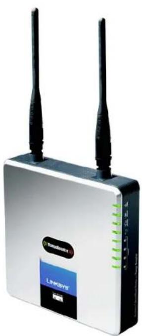
natural_image
Exterior view of a white wireless router with two black antennas and a blue L98051 brand logo (no readable text beyond branding)2,4GHz 802.11g
Sans fil - G
SANS FIL
Onglet Applications and Gaming - Single Port Forwarding (Applications et jeux -
Onglet Applications and Gaming - Port Range Forwarding (Applications et jeux -
Transfert de connexion) 30
Onglet Applications & Gaming - Port Range Triggering (Applications et jeux -
Onglet Administration - Management (Administration - Gestion) 32
Onglet Administration - Log (Administration - Fichier journal) 34
Onglet Administration - Diagnostics 35
Figure 5-35 : Onglet Applications and Gaming - Single Port Forwarding
Figure 5-36 : Onglet Applications and Gaming - Port Range Forward
Figure 5-39 : Onglet Administration - Management (Administration - Gestion) .....32
Figure 5-40 : Onglet Administration - Log (Administration - Fichier Journal)....34
Figure 5-46 : Onglet Administration - Firmware Upgrade
natural_image
Collection of black and white geometric symbols on a light background, no text or labels presentTopologie réseau
text_image
Collection of symbolic and stylized symbols in black, white, and red, including stars, triangles, and circles with various star-like and geometric shapes.Panneau arrière
text_image
Wireless-G BroadBond Roster with Range Boostertext_image
Collection of black and white geometric symbols including stars, squares, and triangles with standard line notationnatural_image
Front view of a network switch with Ethernet port and power indicator (no text or symbols on main components)natural_image
Front view of a network switch with ports and a blue cable (no visible text or symbols)natural_image
Front view of a network switch device showing ports and ports labeled 1, 2, 3, 4 (no readable text beyond labels)text_image
Collection of various geometric symbols and shapes, including asterisks, squares, stars, and triangles with standard line notation.Présentation

text_image
LINKSYS A Software Setup, Inc. Setup Setup Network Settings Internal Connection Type Optional Settings (Required by notes: Internal Service Providers) Network Settings Router IP BNCP Server Setting Time Settings Time Name: Automatic Configuration - DHCP Host name: Domain Name: WU: Auto Size P Address: 162 168 1 Subnet Mask: 290 295 295.0 DHCP Server: Enabled Enabled Data DHCP Start A Address: 162 168 1 100 Minimum Number of Users: 30 P Address Range: 162 1681.100 - 168 Client-Lower Time: 9 minutes (0 means one day) State: SMS 1: 8 0 0 0 State: SMS 2: 8 0 0 0 State: SMS 3: 8 0 0 0 FNG: 8 0 0 0 Save Settings Cancel Changes Browse... Save Settings Cancel ChangesFigure 5-2 : Onglet Setup - Basic Setup (Configuration - Configuration de base)

Figure 5-3 : Type de connexion DHCP

text_image
Internet Connection Type Static IP Internet IP Address: 0, 0, 0, 0 Subnet Music: 0, 0, 0, 0 Default Gateway: 0, 0, 0, 0 DNS 1: 0, 0, 0, 0 DNS 2: 0, 0, 0, 0 DNS 3: 0, 0, 0, 0text_image
Internet Connection Type PPPoE Username: Password Connect on Demand: Max: Idle Time 15 Minutes. Keep Alive: Redial Period 30 Seconds.Figure 5-5 : PPPoE Connection Type (Type de connexion PPPoE)
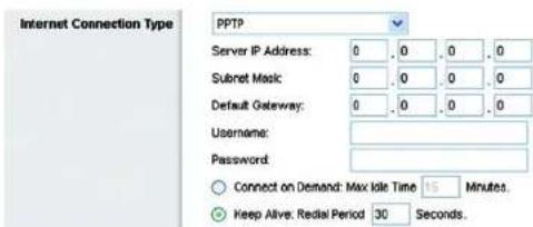
text_image
Internet Connection Type PPTP Server IP Address: 0 0 0 0 Subset Mask: 0 0 0 0 Default Gateway: 0 0 0 0 Username: Password: Connect on Demand: Max Idle Time 15 Minutes. Keep Alive: Redial Period 30 Seconds.Figure 5-6 : PPTP Connection Type (Type de connexion PPTP)
text_image
Internet Connection Type Heart Beat Signal Server IP Address: 0, 0, 0, 0 Username: Password:Figure 5-7 : HeartBeat Signal Connection Type (Type de connexion HeartBeat Signal)
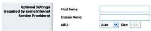
text_image
Optional Settings (required by some Internet Service Providers) Host Name: Domain Name: MTU: Auto Size: 1000text_image
DHCP Server Setting DHCP Server: Enabled Disabled Static DHCP Start IP Address: 192.168.1.100 Maximum Number of Users: 50 IP Address Range: 192.168.1.100 ~ 149 Client Lease Time: 0 minutes (0 means one day) Static DNS 1: 0, 0, 0, 0 Static DNS 2: 0, 0, 0, 0 Static DNS 3: 0, 0, 0, 0 WINS: 0, 0, 0, 0text_image
LINKSYS® A Division of Our Security, Inc. Setup Settings Wireless Security Access Authentication Applications Information Status Status DNS DNS Services DNS-NS.org Username: Password: Host Name: Internal P Address: 102-1881/100 Status Connect Save Settings Cancel Changes Browse... Search SettingsFigure 5-14 : Onglet Setup - DDNS.com (Configuration - DDNS.com)
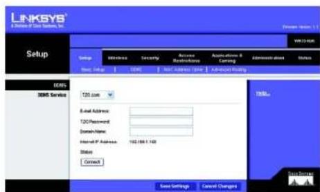
text_image
LINKSYS® A Division of Data Services, Inc. Setup Setup Wireless Security Access Access Restrictions Acquisition & Clearing Administration Status Real Name: 3DS Web Address: 3DS Web-Order Request 3DS Service Email Address: 120/Password: Domain Name: Hemid P Address: 102/488.1.100 Status: Connect Case Settings Cancel Changes TITLE Sign Up/DownFigure 5-15 : Onglet Setup - TZO.com (Configuration - TZO.com)
text_image
LINKSYS Aflouca of Data Systems Inc. Setup Setup Wireless Security Access Instructions Application & Learning Administration Status Basic Setup ONSC MAC Address Close Advanced Pricing MAC Address Clear Enabled Readset MAC Address 00 00 00 00 00 00 Come My PC's MAC Save Settings Cancel Changes OK Save Settings Cancel Changestext_image
LINKSYS® A Division of Data Systems, Inc. Format: 40.0001.1 WRIT263R Setup Setup Infectless Security Access Network Address Applications & Routing Status Stop: Stop OK MAC Address Close Advanced Routing Advanced Routing MAT Enabled Enabled Dynamic Routing (WP) Enabled Enabled Static Routing Route Entries 1 0 Delete This Entry Enter Route Name: Destination LUN(P): 0 0 0 0 Submit Method: 0 0 0 0 Gateway: 0 0 0 0 Interface: LAB & Wireless Show Routing Table Save Settings Cancel Changes Tells... New SourcesFigure 5-17 : Onglet Setup - Advanced Routing (Configuration - Routage avancé)

text_image
LINKSYS® A Division of Close Systems, Inc. Routing Table Destination LAN IP Submit Mask Gateway Interface 10.10.10.100 255.255.255.0 10.10.10.1 Internet (WIN) 192.198.1.109 255.255.255.0 192.198.1.1 LAN & Wireless Refresh CloseFigure 5-18 : Onglet Setup - Routing Table (Configuration - Table de routage)
text_image
LINKSYS A Device of One System, Inc. Wireless Network Settings Access Settings Applications & Settings Administration Other Basic Wireless Settings Wireless Enabled Enabled Network Mode: Mixed Network Name (SSD) Inscurs Channel 8-2.427GHz SSD Download: Enabled Enabled Save Settings Cancel Changes Help... Form SummaryFigure 5-19 : Onglet Wireless - Basic Wireless Settings (Sans fil - Paramètres sans fil de base)
text_image
LINKSYS® A Discount of Data Systems, Inc. Wireless Setup Wireless Security Access Instructions Applications & Routing Administration Status Back Printing Settings Infrastructure Security Wireless MAC Filter Vertical Wireless Settings Wireless Security Security Node: Yes Encryption: 41 154-bit (19 hndight) Peripherals: Consents Next: Next-2 Next-3 Next-4 TX key: 1 Save Settings Cancel Changes Edit... New ResourcesFigure 5-20 : Onglet Wireless - Wireless Security (WEP) (Sans fil - Sécurité sans fil (WEP))
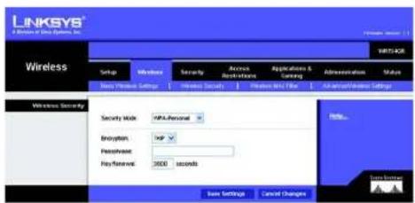
text_image
LINKSYS A Division of Data Systems, Inc. Wireless Setup Windows Security Access Applications Applications & Casing Administration Status New Printset Settings Internet Security Printout Mail Filter An American Windows Settings Wireless Security Security Mode: HPL-Personal Encryption: TCP Pre Slovenia: 3500 seconds Data Settings Cancel Changes Help... Data SettingsFigure 5-21 : Onglet Wireless - Wireless Security (WPA Personal) (Sans fil - Sécurité sans fil (WPA personnel))

text_image
LINKSYS A Division of Data Systems, Inc. Wireless Setup Wireless Security Access Accessories & Cataling Address protection Shares New Windows Settings Forward Security Forward Net Filter Advanced Release Settings Wireless Security Security Mode: F502 Encryption: 405 Peripherals: Key Network: 1800 seconds Save Settings Cancel Changes Help... Save Programs Cancel ChangesFigure 5-22 : Onglet Wireless - Wireless Security (PSK2) (Sans fil - Sécurité sans fil (PSK2))
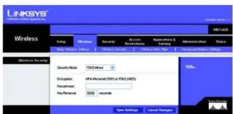
text_image
LINKSYS A Division of Data Systems, Inc. WIRELLAER Wireless Setup Wire class Security Access Network Applications & Coding Address/Session Status Next Wireless Setup Private Security Parallel MAC Web Access and Privacy Settings Wireless Security Security Mode: FSGD-Mixed Decryption: HPS-Personal (TIP) or FSGD (MDS) Passense: KeyRenewal: 1000 seconds Spin Settings Cancel Changes Help... Data PrivacyFigure 5-23 : Onglet Wireless - Wireless Security (PSK2-Mixed) (Sans fil - Sécurité sans fil (PSK2 mixte))
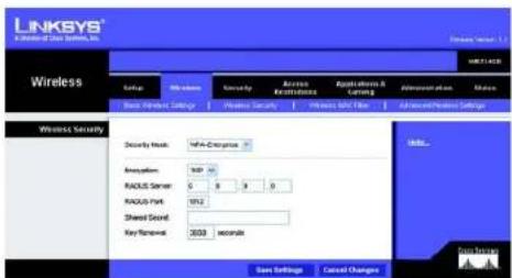
text_image
LINKSYS A Wireless Data Server, Inc. Wireless Setup Wireless Security Access Access to Security Access to Network Administrative Plan Access Base: Windows Settings Maintenance Security Pre-Service Band Filter Advanced/Pre-Service Settings Wireless Security Security Work: WPC-Extensions Application: TCP 10 RADIUS Server: 0 5 9 0 RADIUS Park: 1912 Shared Sound: Key Window: 3000 seconds Size Settings Cancel Changes Help... Fire HistoryFigure 5-24 : Onglet Wireless - Wireless Security (WPA Enterprise) (Sans fil - Sécurité sans fil (WPA entreprise))
text_image
LINKSYS A Division of One System, Inc. Wireless Group Windows Security Apache Instructions Application & Leasing Administration Other Deep Wireless Settings Wireless Security Wireless Security Wireless Security Security Mask: PSACHACKS Shropafen: AIS PAAUS Server: 0 4 9 9 PAAUS Port: NT2 Shared Secret: Key Eventset: 3500 seconds Save Settings Cancel Changes Send... Close SecurityFigure 5-25 : Onglet Wireless - Wireless Security (PSK2 RADIUS) (Sans fil - Sécurité sans fil (PSK2 RADIUS))
text_image
LINKSYS® A Division of Data System, Inc. Wireless Setup Wireless Security Access Access Features Applications & Settings Information Edit Back Windows Settings Wireless Security Wireless Security Settings Wireless Security Security Mode: RADIUS RADIUS Server: 0 8 3 0 RADIUS Port: W12 Shared Secret: Deviation: 45/16.64 (10 hex digits) PresPFrase: Commands Key1: Key2: Key3: Key4: TX Key: 1 Save Settings Cancel Changes Web... WinburgFigure 5-26 : Onglet Wireless - Wireless Security (RADIUS) (Sans fil - Sécurité sans fil (RADIUS))
text_image
LINKSYS A Network of Data Networks, Inc. Network Settings Wireless Networks MAC Filter Access Realization MAC Address Filter List Internet Enabled Present PCs listed below from accessing the wireless network. Permit PCs listed below to access the wireless network. Wireless Client List MAC 01 30:00:00:00:00 MAC 08 30:00:00:00:00 MAC 02 30:00:00:00:00 MAC 13 30:00:00:00:00 MAC 03 30:00:00:00:00 MAC 14 30:00:00:00:00 MAC 04 30:00:00:00:00 MAC 15 30:00:00:00:00 MAC 05 30:00:00:00:00 MAC 16 30:00:00:00:00 MAC 06 30:00:00:00:00 MAC 17 30:00:00:00:00 MAC 07 30:00:00:00:00 MAC 18 30:00:00:00:00 MAC 08 30:00:00:00:00 MAC 19 30:00:00:00:00 Save Settings Cancel Changes Unit... Send SettingsFigure 5-27 : Onglet Wireless - Wireless MAC Filter (Sans fil - Filtre MAC sans fil)

text_image
LINKSYS A Division Of Data Systems, Inc. Wireless Client Ltd Sort by IP Address Client Name Interface IP Address MAC Address Status Save to MAC Address Filter List Linkya 1 Wireless-0 192 196.1 100 00:40:05 36/CE 81 Connected □ Linkya 2 Wireless-A 193 198.1 101 00:40:06 36/CE 82 Recommended □ Linkya 3 Wireless-B 193 198.1 100 00:40:06 36/CE 83 Connected □ OK Finish CancelFigure 5-28 : Wireless Client List (Liste des clients sans fil)
text_image
LINKSYS A License at Data Systems, Inc. Security Setup Wireless Security Access Bioservices Applications & Testing Administration Status Formal VPN Search Network SP/Naval Protection Enabled Enabled Internet Filters Fiber Anonymous Internet Requests Fiber Multisat Fiber Internet NAT Redirection Fiber EN1 (Port 113) Web Filters Java Java ActiveX Cookies Save Settings Cancel Changes Help... False Settingstext_image
LINKSYS® A Division of Our Service, Inc. Security Setup Windows Security Access Networks Applications & Learning Administration Status UPF Searchthrough Plan Searchthrough L3IP Searchthrough PPT Searchthrough Enabled Enabled Enabled Enabled Enabled Help... Up Subway OKFigure 5-31 : Onglet Security - VPN Passthrough (Sécurité - Intercommunication VPN)
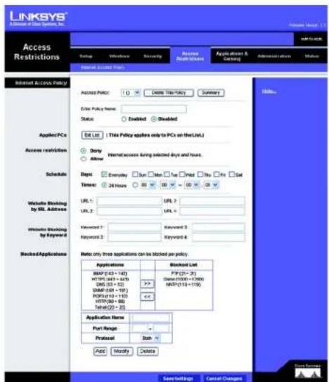
text_image
LINKSYS® A Division of Data Providers, Inc. Access Restrictions Form 10 Internal Access Rules Internet Access Policy Access Policy: 10 License Tax Policy Summary Enter Policy Name: Status: Enabled Enabled Edit List ( This Policy applies only to PCs on the List.) Apply PCs Access restrictions Schedule Done Allow Internal access timing selected days and hours. Sign: Everyday Sun Min Tue Paid You Fri Set Taxes: 24 Hours 80 60 50 40 30 20 Website Blocking by URL Address URL 1: URL 2 URL 2: URL 3 Website Blocking by Keyword Keyword 1: Keyword 2 Keyword 2: Keyword 3 Keyword 4 Rejected Applications Note: only three applications can be blocked by proxy. Applications Blocked List MSP (63 + 143) PIP (21 - 36) HTTPG (63 + 619) Date (1/10) + (1/99) DNS (33 + 52) MWD (113 + 176) SMAF (58 + 119) <> PORTG (13 + 115) HTTPG (80 - 88) Telnet(22 + 20) Application Name: Port Range: Protocol Sub Add Modify Delete Save Soft Caps Cancel Changes Help... Save Soft Caps Cancel Changestext_image
LINKSYS® 8 Division of Data Systems, Inc. List of PCs MAC Address 01 00:00:00:00:00 36 00:00:00:00:00 02 00:00:00:00:00 57 00:00:00:00:00 03 00:00:00:00:00 58 00:00:00:00:00 04 00:00:00:00:00 39 00:00:00:00:00 05 00:00:00:00:00 13 00:00:00:00:00 IP Address 01 192.168.1.9 34 192.168.1.9 02 192.168.1.9 35 192.168.1.9 03 192.168.1.9 36 192.168.1.9 IP Address Range 01 192.168.1.9 = 33 192.168.1.9 = 3 02 192.168.1.9 = 34 192.168.1.9 = 3 Gain Settings Cancel Change Closetext_image
LINKSYS® A Division Data System, Inc. Applications & Gaming Start Wireless Security Access Accessories Application Details & Gaming Application status Status Start Start Frequency Start Range Forwarding Start Range Insgms OK Part Range Triggering Application Name Triggered Range Forwarded Range Enabled Save Settings Cancel Changes MILs... New PlayOnglet Administration - Management (Administration - Gestion)
text_image
LINKSYS® Access to Other Systems, Inc. Administration Set up Vehicles Security Access Authentication Authentication & Coding Administration Status Management Log Settings Functional Details Forward Settings Management Router Access Router Protocol: Router to Confirm: Web Access Web Utility access: Web Utility access via Windows... Remote Access Remote Management: Remote Gateway: Remote Updates: Allowed Remote IP Address: Any IP Address: Remote Management/Path: Backup Configurations Backup Configurations Backup and Settings UPV Enabled Enabled User to Configure: Enabled User to Configure TCP/IP Enabled User to Configure TCP/IP Enabled User to Configure TCP/IP Enabled User to Configure TCP/IP Enabled User to Configure TCP/IP Enabled User to Configure TCP/IP Enabled User to Configure TCP/IP Enabled User to Configure TCP/IP Enabled User to Configure TCP/IP Enabled User to Configure TCP/IP Enabled User to Configure TCP/IP Enabled User to Configure TCP/IP Enabled User to Configure TCP/IP Enabled User to Configure TCP/IP Enabled User to Configure TCP/IP Enabled Users to Configure: Enabled Users to Configure TCP/IP Enabled Users to Configure TCP/IP Enabled Users to Configure TCP/IP Enabled Users to Configure TCP/IP Enabled Users to Configure TCP/IP Enabled Users to Configure TCP/IP Enabled Users to Configure TCP/IP Enabled Users to Configure TCP/IP Enabled Users to Configure TCP/IP Enabled Users to Configure TCP/IP Enabled Users to Configure TCP/IP Enabled Users to Configure TCP/IP Enabled Users to Configure TCP/IP Enabled Users to Configure TCP/IP Enabled Users to Configure TCP/IP Enabled User to Configure: Enabled User to Configure TCP/IP Enabled User to Configure TCP/IP Enabled User to Configure TCP/IP Enabled User to Configure TCP/IP Enabled User to Configure TCP/IP Enabled User to Configure TCP/IP Enabled User to Configure TCP/IP Enabled User to Configure TCP/IP Enabled User to Configure TCP/IP Enabled User to Configure TCP/IP Enabled User to Configure TCP/IP Enabled User to Configure TCP/IP Enabled User to Configure TCP/IP Enabled User in a software system: Not Applicable or Not EnabledFigure 5-39 : Onglet Administration - Management (Administration - Gestion)
text_image
LINKSYS www.rinksys.com Administration Setup Wireless Security Access Restrictions Applications & Earning Advanced Option Status Log Enabled Enabled LogEnter P Address: 102.168.1..0 View Log Help... Save Settings Cancel Changes Edit OptionsFigure 5-40 : Onglet Administration - Log (Administration - Fichier Journal)

text_image
LINKSYS® * Division Of Data Systems, Inc. Log Type Incoming Log Source IP Address Destination Port Number 10/10/10:100 %e Save the Log Refresh ClearOnglet Administration - Diagnostics
text_image
LINKSYS A Division of Data System, Inc. Administration Setup Welcome Security Access Access to Data Systems Application & Control Administrative Options Settings Management Log Diagnostic Factory Details Hardware System Dependencies Ping Text P: or URL Address: Packed Size: 32 Index(32-9804) Time to Ping: 5 Start to Ping Transmitted Text P: or URL Address: Start to Transmitted 100% Send SummaryFigure 5-42 : Onglet Administration - Diagnostics

text_image
LINKSYS® A Driver of Data Systems, Inc. FINGING SAVOC.COM (215-09.12472) with 32 types of data: Reply from 215-09.12472: type=52 types=80tes TTL+6 CloseFigure 5-43 : Test Ping
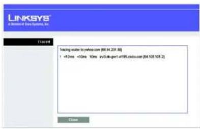
text_image
LINKSYS® A division of https://sys.org/ 10.24.001 Tracking server to yelcom.com (86.34.231.88) +10 ms +92ms 10ms i=348-gpt-4195.cdcio.com (84.101.101.2) Closetext_image
LINKSYS® A Division of China Systems, Inc. Administration Setup Workloads Security Access Restrictures Applications & Carriers Administration Status Management Log Requested Funding Details Recommended Factory Defaults Custom Factor Defaults Factory Defaults This version allows you to repeat all the Student's construction without the free default vector Data librarytext_image
LINKSYS® A Division of Class Systems, Inc. Administration Setup Ultrate Security Russan Reriviness Applications & Landing Accessories Status Management Up Deposits Policy Controls Personal Upgrade Hardware Upgrade Please Select a Web Upgrade Browse Start to Upgrade Upgrade: Upgrading from the Web interface, please default on the power or power the next button. 90% Upgrade must NOT be interrupted it Hardware Upgrade Features: User Interface to access by the Software Upgrade Button. After <|vision_start|> user interface, which can be installed from the Next Service www.1885.com. Data Viewstext_image
LINKSYS® A Window for Our Options, Inc. Status: SET Windows Security Access Access Number Applications & Controls Administration Status Register Local Information Report Services Faster Information Firmware Version: cV.81 Current Time: Not Available Internal MAC Address: 89/00/00/01/57 Host Name: Lethops Cancer Status: Lethops Internet Connection Connection Type: Automatic Configuration - DHCP Internal IP Address: 16.16.1.59 Submit Mask: 205.355.255.248 Default Delivery: 16.16.1.5 DNS1: 200.388.5.1 DNS2: 200.388.5.2 DNS3: 200.388.5.3 MTU: Auto Expired Time: 2 Days 9 Min IP Address Release IP Address Remove Refreshtext_image
LINKSYS AChosen of Data Systems Inc. Status: WNT100R Setup Windows Security Access Restrictions Applications & Settings Administration Status Scale Large/Network Please Network Router Information Password Version: eL81 Current Type: Not Available Internal MAC Address: 00.0100.020157 Host Name: Linkage Domain Name: Linkage Internet Connection Connection Type: PPPeE Status: Connected Internal IP Address: 16.31.3.10 Submit Next: 206.306.256.248 Default Gateway: 16.31.3.1 DNS1: 206.306.1.1 DNS2: 206.306.1.2 DNS3: 206.306.1.3 Download Refreshtext_image
LINKSYS A Division of Data Systems, Inc. Status: SET Status Wireless Security Access Not Applicable Applications & Testing Administrative Status List of Networks Local MAC Address 88.00.00.01/07 Local P Address 192.00.5.1 Subnet Address 296.00.2004 DNSP Server Enabled Local P Address 192.00.5.1/08 DNSP Address 192.00.5.1/08 DNSP Card Data Data FromFigure 5-49 : Onglet Status - Local Network (Etat - Réseau local)

text_image
LINKSYS A Division of Data Systems, Inc. LINKS Client Table To Sort by P Address Client Name Interface P Address BAC Address Expired Time Linksys 1 LAN 192.168.1.100 03:48:05:35 CE:40 20hr56min 77sec Delete Linksys 2 Wireless-4 192.168.1.101 03:48:05:35 CE:40 20hr56min 77sec Delete Linksys 3 Wireless-0 192.168.1.102 03:48:05:35 CE:40 20hr56min 77sec Delete Linksys 4 Wireless-8 192.168.1.103 03:48:05:35 CE:40 20hr56min 77sec Delete Refresh Closetext_image
LINKSYS A Division of Sos Systems, Inc. Status Design Windows Security Access Mac Networks Application & Gaming Show Local Network Funding Service MAC Address 新收帐帐表57 Work Mixed Network Name (GSE) Balance Channel 8 - 240MHz Security WIP-Personal GSE Broadcast Enland Status:\ Email: Form Energytext_image
LINKSYS® A Division of Case Systems, Inc. Formware Service: 1.1 Administration SETUP Vehicles Security Access Instructions Applications & Earning Additionation Status Management Log De Diagnostics Factory Oficia Forward Upgrade Firmware Upgrade Please Select a File by Upgrade Browse... Start to Upgrade UAE Upgrade Upgrade Formware Use is upgraded by clicking the Software. Upgrade Subscribers after launching for the Software, which will be downloaded from the Linksys website "ServiceNow, Ltd." Upgrade must NOT be interrupted!! Data Source:text_image
LINKSYS Linksys 1 Windows 2 Windows 3 Bluetooth Client List Settings P Address Client Name Interface P Address MIC Address Status Case to MAC Address Filter List Linksys 1 Windows-0 150.169.1 / 100 80.40.65 35 CE:03 Connected □ Linksys 2 Windows-A 150.169.1 / 100 80.40.65 35 CE:02 Disconnected □ Linksys 3 Windows-B 150.169.1 / 100 80.40.65 35 CE:03 Connected □ Add Refresh CaseFigure E-5 : Wireless Client List (Liste des clients sans fil)
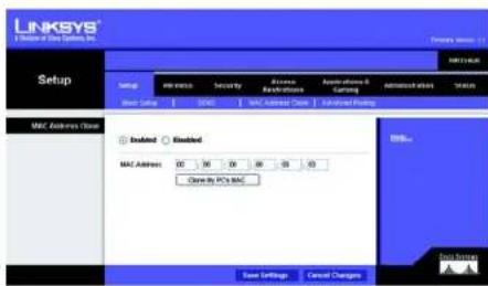
text_image
LINKSYS Setup MAC Address Close MAC Address 00 30 50 60 80 10 Close by PC's MAC Save Settings Cancel Changes MAC Address MAC Address Close Advanced Setting MAC Address MAC Address MAC Address MAC Address MAC Address MAC Address MAC Address MAC Address MAC Address MAC Address MAC Address MAC Address MAC Address MAC Address MAC Address MAC Address MAC Address MAC Address MAC Address MAC Address MAC Address MAC Address MAC Address MAC Address MAC Address MAC Address MAC Address MAC Address MAC Address MAC Address MAC Address MAC Address MAC Address MAC AddressFigure E-6 : MAC Address Cloning (Clonage de l'adresse MAC)
Certifications FCC, Wi-Fi, CE
This device complies with Canadian ICES-003 and RSS210 rules.
This product may be used in all EU countries (and other countries following the EU directive 1999/5/EC) without any limitation except for the countries mentioned below:
The Belgian Institute for Postal Services and Telecommunications (BIPT) must be notified of any outdoor wireless link having a range exceeding 300 meters. Please check http://www.bipt.be for more details.
In case the product is used outdoors, the output power is restricted in some parts of the band. See Table 1 or check http://www.arcep.fr/ for more details.
Environmental Information for Customers in the European Union
European Directive 2002/96/EC requires that the equipment bearing this symbol on the product and/or its packaging must not be disposed of with unsorted municipal waste. The symbol indicates that this product should be disposed of separately from regular household waste streams. It is your responsibility to dispose of this and other electric and electronic equipment via designated collection facilities appointed by the government or local authorities. Correct disposal and recycling will help prevent potential negative consequences to the environment and human health. For more detailed information about the disposal of your old equipment, please contact your local authorities, waste disposal service, or the shop where you purchased the product.