MAC 250 B - Lawn mower MCCULLOCH - Free user manual and instructions
Find the device manual for free MAC 250 B MCCULLOCH in PDF.

User questions about MAC 250 B MCCULLOCH
0 question about this device. Answer the ones you know or ask your own.
Ask a new question about this device
Download the instructions for your Lawn mower in PDF format for free! Find your manual MAC 250 B - MCCULLOCH and take your electronic device back in hand. On this page are published all the documents necessary for the use of your device. MAC 250 B by MCCULLOCH.
USER MANUAL MAC 250 B MCCULLOCH
text_image
McCULLOCHMAC 250 B
natural_image
Line drawing of a person performing a physical exercise with arms and legs (no text or symbols)GB
INSTRUCTIONMANUAL
IMPORTANTINFORMATION: Pleasereadtheseinstructionscarefullyandmake sureyouunderstandthembeforeusingthisunit.Retaintheseinstructionsforfuture reference.
FR
MANUELD'INSTRUCTIONS
text_image
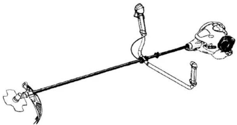
Technical diagram of a medical or robotic device with numbered components and labeled parts, likely for scientific or technical documentation.1.Fueltank
2.Handlebar
3.ON/STOPswitch
4.Throttlecableclip
5.Shoulderharnessclamp
6. Shoulderharness
7. Trimmerhead
8. Linelimiterblade
9. Combinationshield
10.Shaft
11.Blade
12.Throttletrigger
- Throttlelock--out
14.Startthrottlebutton
15.Starterhandle
16.Fuelcap
17.Primerbulb - Chokelever
19.Muffler
20.Wrench
21.Hexwrench - Transportguard
23.Instructionmanual
IDENTIFICATIONOFSYMBOLS
A.

D.
F.
B.

E.

G.
J.

C.


H.

K.

A. WARNING! This brushcutter can be dangerous! Care less or improper use can cause serious or even fatal injury.
B.Readandunderstandtheinstructionmanualbeforeusingthebrushcutter.
C. Alwaysuse
Earprotection, eyeprotection, headprotection, boots, and gloves.
D. DANGER! Blade can thrust violently away from material it does not cut. Blade thrustcancauseamputationofarmsorlegs.Keeppeopleandanimals15meters away.
E. WARNING! Blade/trimmer line can throw objects violently. You and others can be blindedorinjured. Alwaysweareyeprotectionandlegprotection.
F. The operator of themachinemustinsurethatnoonecomeswithina15meterradius whileworking. Whenseveraloperatorsareworkingwithinthesameareaasafetydistanceofatleast15metersmustbeobserved.
G.Useunleadedorqualityleadedpetrolandtwo-strokeoilmixedataratioof2.5%.
H. Handlebartobepositionedonlybelowthearrow.
I. EngineON/STOPSwitch.
J.GuaranteedsoundpowerlevelaccordingtoDirective2000/14/EC
K.Maximumrotationalfrequencyofthespindle,rpm
SAFETYRULES

WARNING: When using gardening
appliances, basicsafety precaution should always be followed to reduce risk of fire and serious injury. Read and follow wall instructions.

DANGER: This power tool can be
dangerous!Thisunitcancauseseriousinjury includingamputationorblindnesstothep- oratorandothers. Thewarningsandsafety instructions in this manual must be followed to providereasonablesafetyandefficiencyin usingtheunit. Theoperatorisresponsiblefor followingthewarningsandinstructionsin this manualandontheunit.Readtheentireinstructionmanualbeforeassemblingandusing the unit! Restrict the use of this unit to personswhoread,understand,andfollowthe warningsandinstructionsin this manual and ontheunit.Neverallowchildrentooperate thisunit.

INSTRUCTION MANUAL
SAFETYINFORMATION
ONTHEUNIT

DANGER:Bladecanthrustviolently
away from material it does not cut. Blade thrustcancauseamputationofarmsorlegs. Keeppeopleandanimals15metersaway.

text_image
Warning sign depicting a circular object with spiral and directional arrows, indicating hazard or accident risk.WARNING: Blade/trimmerline can throw objects violently. You and others can be blinded or injured. Wearsafety glasses and leg protection.

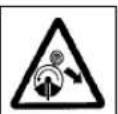
text_image
Warning sign showing three circular icons with protective symbols and a triangular warning triangle indicating safety hazard.WARNING: Hazardzoneforthrown objects. Blade/Trimmerlinecanthrowobjects violently. Otherscanbeblindedorinjured. Keeppeopleandanimals15metersaway.

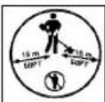
text_image
HazardZone 15 m 15 m 50FT 50FTWARNING: Donotusetrimmerhead asafasteningdevicefortheblade.

text_image
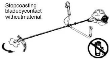
Prohibition sign with pictogram of a person crossing a circle, indicating no smoking or alcohol useWARNING: The bladecontinuesto spinafterthethrottleisreleasedor, engineis turnedoff. The coastingbladecanthrowobjects orseriouslycutifaccidentallytouched. Stop the bladebycontactingtherighthandsideofthe coastingbladewithmaterialalreadycut.
Stopcoasting bladebycontact withcutmaterial.
text_image
Stopcoasting bladebycontact withcutmaterial.OPERATORSAFETY
WARNING: This machine produces anelectromagneticfieldduringoperation.Under somecircumstances,thisfieldmayinterfere withactiveorpassivemedicalimplants.Toreducetheriskofseriousorfatalinjury,werecommendpersonswithmedicalimplantstoconsult theirphysicianandthemedical implant manufacturerbeforeoperatingthismachine.
- Dress properly. Always wear safety glassesorsimilareyeprotectionwhenoperating.or performingmaintenance.on
yourunit(safetyglassesareavailable). EyeprotectionsshouldbemarkedZ87.
• Always wear a helmet if the trees to be clearedaretallerthan2meters.
•Alwayswearfaceordustmaskifoperation isdusty.
• Always wear heavy, long pants, long sleeves, boots, and gloves. Wearingsafety legguards is recommended.
•Alwayswearfootprotection.Donotgo barefootorwearsandals.Stayclearof blade/spinningline.
- Securehairaboveshoulderlength.Secure orremovelooseclothingorclothingwith looselyhangingties,straps,tassels,etc. Theycanbecaughtinmovingparts.
- Beingfullycoveredalsohelpsprotectyou from debris and pieces of toxic plants thrownbyspinningline.
- Stayalert.Donotoperatethisunitwhenyou aretired,ill,upsetorundertheinfluenceofalcohol,drugs,omedication.Watchwhatyou aredoing;usecommonsense.
- Wearhearingprotection. Longorcontinuous exposure to high noise levels may cause permanent hearing impairment.
• Mufflersfittedwithcatalyticconvertersget veryhotduringuseandremainsoforsome timeafterstopping. Thisalsoappliesatidle speed.Contactcanresultinburnstotheskin. Remembertheriskoffire!
- Neverstartorruninsideaclosedroomor building.Breathingexhaustfumescankill.
- Keephandlesfreeofoilandfuel.
•Alwaysusethehandlebarandaproperly adjustedshoulderharnesswithablade (seeASSEMBLY).
UNIT/MAINTENANCESAFETY
WARNING:Stopunitanddisconnect the spark plug before performing maintenance(exceptcarburetoradjustments).
- Throwawaybladesthatarebent, warped, cracked, broken, ordamagedin anyother way. Replacetrimmerheadpartsthatare cracked, chipped, broken, ordamagedin anyotherway before using the unit.
- Maintainunitaccordingtorecommended procedures.Keepbladesharp.Keepcuttinglineattheproperlength.
- Useonly2,4mmdiameterMcCulloch brandreplacementline.Neverusewire, rope, string, etc.
• Installrequiredshieldproperlybeforeusing theunit.
- Useonlyspecifiedbladeortrimmerhead; makesureitisproperlyinstalledandsecurelyfastened.
- Neverstartenginewithclutchshroudremoved. The clutchcanflyoffandcauseseriousinjury.
- Besurebladeortrimmerheadstopsturning whenengineidles.
- Makecarburetoradjustmentswiththelowerendsupportedtopreventbladeortrimmerlinefromcontactinganyobject.Hold unitbyhand;donotusetheshoulderharnessforsupport.
- Keepothersawaywhenmakingcarbure-toradjustments.
- UseonlyrecommendedMcCullochaccessoriesandreplacementparts.
- Have all maintenance and servicenotexplained in this manual performed by your authorised serviced dealer.
FUELSAFETY
•Mixandpourfueloutdoors.
- Keepawayfromsparksorflames.
• Useacontainerapprovedforfuel.
- Donotsmokeorallowsmokingnearfuelor theunit.
- Avoidspillingfueloroil.Wipeupallfuelspills.
- Moveatleast3metersawayfromfueling sitebeforestartingengine.
- Stopengine and allow to cool before moving fuel cap.
•Alwaysstorepetrolinacontainerapproved forflammableliquids.
CUTTINGSAFETY

WARNING:Inspecttheareatobecut
beforeeachuse.Removeobjects(rocks, brokenglass,nails,wire,string,etc.)which canbethrownorbecomeentangledinthe bladeortrimmerhead.
- Keepothersincludingchildren,animals, bystanders,andhelpersatleast50feet(15 meters)away.Stopengineimmediatelyif youareapproached.
•Alwayskeepengineontheright--handside ofyourbody.
- Holdtheunitfirmlywithbothhands.
- Keepfirmfootingandbalance.Donot overreach.
- Keepbladeortrimmerheadbelowwaist level.Donotraiseengineaboveyourwaist.
- Keepallpartsofyourbodyawayfromblade, trimmerhead,andmufflerwhenengineis running.Ahotmufflercancauseserious burns.
- Cutfromyourlefttoyourright.Cuttingon rightsideoftheshieldwillthrowdebris awayfromtheoperator.
•Useonlyindaylightorgoodartificiallight.
• Useonlyforjobsexplainedinthismanual. - Allowtheenginetocool;secureunitbefore storingortransportinginvehicle.
- Emptyfueltankbeforestoringortransporting theunit.Useupfuelleftinthecarburetorby startingengineandlettingitrununtilstops.
- Storeunitandfuelinanareawherefuelvaporscannotreachsparksoropenflames fromwaterheaters,electricmotorsor switches,furnaces,etc.
- Storeunitsolinelimitercannotaccidentally causeinjury. Unitcanbehungbytheshaft.
- Alwaysinstalltransportguardonbladebeforetransportingorstrorage.
- Storetheunitoutofthereachofchildren.
- Securethemachineduringtransport.
SPECIALNOTICE: Exposuretovibrations
throughprolongeduseofpetrolpoweredhand toolscouldcausebloodvesselomervedamageinthefingers,hands,andjointsofpeople pronetocirculationdisordersorabnormalswellings.Prolongeduseincoldweatherhasbeen linkedtobloodvesseldamageinotherwise healthypeople.lfsymptomsoccursuchas numbness,pain,lossofstrength,changeinskin colorortexture,orlossoffelinginthefingers, hands,orjoints,discontinuetheuseofthistool andseekmedicalattention.Ananti-vibration systemdoesnotguaranteetheavoidanceof theseproblems.Userswhooperatepowertools onacontinualandregularbasismustmonitor closelytheirphysicalconditionandthecondition ofthistool.
TRANSPORTINGANDSTORAGE
ASSEMBLY
CARTONCONTENTS
Checkcartoncontentsagainstthefollowinglist:
- Brushcutter
- Blade
• Cuppedwasher
•Largenutforinstallingblade - Trimmerhead
•Combinationshield
•Bolt - Handlebar
•Handlebarbracketcover
•Handlebarbracketcoverscrews(2)
•Uppershoulderharnessclamp
•Lowershoulderhamessclamp -
Shoulderharnessclampscrews(2)
-
Shoulderharness
•Hexwrench
•Wrench
•Transportguard
•Throttlecableclip

WARNING:Alwaysstopunitanddis-
connectsparkplugbeforeperforminganyassemblyprocedures.

WARNING: If received assembled,
repeatallstepstoensureyourunitisproperly assembledandallfastenersaresecure. Examinepartsfordamage.Donotusedamagedparts.
Itisnormalforthefuelfiltertorattleinthe emptyfueltank.
Findingfueloroilresidueonmufflerisnormal duetocarburetoradjustmentsandtesting donebythemanufacturer.
TOOLSREQUIRED
•Hexwrench(provided)
-Adjustablewrench
•Phillipsscrewdriver
ATTACHINGTHEHANDLEBAR

DANGER: To avoid serious injury, the barrierportionofthehandlebarmustbeinstalled asshowntoprovideabarrierbetweenoperator andthespinningblade.
- Removethescrewattherearofthe throttlehandle.
2.Slidethethrottlehandleontotherightside ofthehandlebar(seeillustration). - Alignthescrewholeinthethrottlehandle with the hole in the handle bar.
- Refitthescrewintheholeintherearofthe throttlehandle.
- Screwthescrewthroughthehandleand handlebar.Tightenthescrew.
6.Fitthemountingcomponentsasshown.

natural_image
Technical line drawing of a mechanical assembly with a magnified inset showing a component detail (no text or symbols)-
The handlebarmounting must be fitted between the arrows on the shaft.
-
Tightenthescrewswithahexwrench.
ASSEMBLYOFSHOULDER HARNESS

WARNING: When using abrushcut-
ter, it must always be hooked securely to the shoulder harness. Otherwise, you will be unabletosafely control the brush cutter. This can result in injury to yourself for others. Propers shoulder harness and handle bar adjustments must be made with the engine completely stopped before using unit. Well-adjusted shoulder harness and machine makes work much easier.
ATTACHINGSHOULDERHARNESS CLAMP
- Placetheuppershoulderharnessclamp overtheshaft.
- Position the lowers shoulder harness clampundertheshaft and align the upper and lower clamps crewholes. Clamp must be fittle abovethe arrow on the shaft (see illustration above).
NOTE: Fitthrottlewireingrooveoflower harnessclampbeforetighteningscrews.
- Inserttwoscrewsintothescrewholes.
- Secureshoulderharnessclampbytighteningscrewswithahexwrench.
SHOULDERHARNESS ADJUSTMENT
Atthefrontoftheshoulderharnessisaneasily accessiblequickrelease. Usethequickrelease inanyemergencysituationthatrequiresyouto freeyourselffromthemachineandharness.

natural_image
Illustration of two hands adjusting a belt buckle, showing correct and incorrect states (no text or symbols)- Putontheharness.Adjusttheharnessfor thebestworkingposition.
- Tensionthesidestrapsssothattheweight is evenly distributed across both shoulders.

natural_image
Line drawing of a person wearing a hard hat and safety vest (no text or symbols)NOTE: It may be necessary to relocate the shoulder harness clamp on the shaft for proper balancing of unit.

text_image
SHOULDERHARNESS ADJUSTMENT FORBALANCE 15cm below waist 76cm 10-30cm above ground
text_image
76cmATTACHINGTHESHIELD
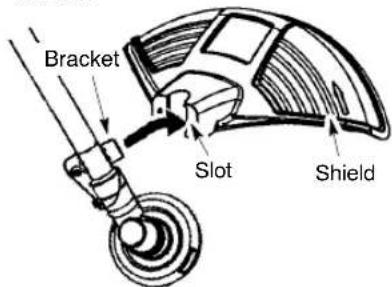
WARNING: Theshieldmustbeproperlyinstalled. Theshieldprovidespartial protectiontotheoperatorandothersfrom the riskofthrownobjects, andisequippedwitha linelimiterbladewhichcutsexcesslinetothe properlength. Thelinelimiterblade(onundersideofshield)issharpandcancutyou. 1. Insertbracketintoslotonshield. 2. Pivotshieldtoalignholesinshieldand bracket.
text_image
Bracket Slot Shield- Secureshieldtobracketwithbolt.
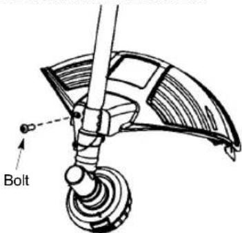
text_image
BoltCONFIGURINGYOURUNIT
Youcanconfigureyourunitusingacuttinghead forgrassandlightweeds,oraweedbladefor cuttinggrass,weeds,andbrushupto1cmin diameter.Toassembleyourunit,gotothesectionforthedesiredconfigurationandfollowthe instructions.
ASSEMBLYINFORMATION--TRIMMERHEAD

text_image
TRIMMER HEADNOTE: Removetheblade before attaching the trimmerhead. Toremoveblade, alignhole in the dustcup with the hole in the side of the gearbox by rotating the blade. Insertasmall screwdriver into aligned holes. This will keep the shaft from turning while loosening the blade nut. Remove bladenut by turning clockwise. Removethescrewdriver. Remove both washers and blade. See INSTALLATION OF THE METAL BLADE for illustrations. Besuretostore all parts and instructions for future use.
INSTALLATION OF THE TRIMMER HEAD
NOTE: If your unithasaplastic cover over the threadsonthethreaded shaft, remove the covering to exposethethreads. Before installing the trimmer head, makes sure the dust cup and retaining washer are positioned on the gearbox as shown below.
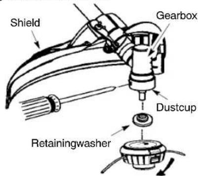
text_image
Shield Gearbox Dustcup RetainingwasherNOTE: Makesureallpartsareproperly installedasshownintheillustrationbefore installingthetrimmerhead.
- Alignholeinthedustcupwiththeholeinthe sideofthegearboxbyrotatingthedustcup.
- Insert a small screwdriver into aligned holes. This will keep the shaft from turning while tightening trimmer head.
- While holding the screw driver in position, thread trimmer head onto the shaft in the directions shown on the decal (counterclockwise). Tighten until secure.
NOTE: Theretainingwashemustbepositionedwiththeraisedsectionfacingtowardthe gearbox.
ASSEMBLYINFORMATION--WEED BLADE

text_image
WEED BLADENOTE: Removethetrimmerheadbefore Installingtheweedblade. Toremovethetrim- merhead, alignholeinthedustcupwiththehole inthesideofthegearboxyrotatingthedust cup. Insertasmallscrewdriverintoaligned holes. Thiswillkeeptheshaftfromturningwhile looseningethetrimmerhead. Removethetrim- merheadbyturningclockwise. Removethe screwdriver. SeeINSTALLATIONOFTHE TRIMMERHEADforillustrations.Besureto storeallpartsandinstructionsforfutureuse. Neverusethetrimmerheadwiththemetal bladeinstalled.
INSTALLATIONOFTHEMETAL BLADE
WARNING: Wearprotectivegloves whenhandlingorperformingmaintenanceon thebladetoavoidinjury. Thebladeissharpand cancutyouevenwhenitisnotmoving.
WARNING: Donotuseanyblades, or fasteninghardwareotherthanthewashersand nutsshowninthefollowingillustrations. These partsmustbeprovidedbyMcCullochand installedasshownbelow.Failureretouseproper partscancausethebladetofyoffandseriously hurtyouorothers.
NOTE: The dust cup is located on the gearbox shaft and not in the parts bag. All other fasteners mentioned in the following assembly steps are in the parts bag.
- Installthebladeandtheretainingwasher over thethreadedshaft.
- Makesuretheraisedpartofthe retaining washerisfacingthegearboxandtheraised areafitsintotheholeinthecenterofthe blade.
- Slidethe bladeandretainingwasheronto theshaftofthe gearbox.
- Placethecuppedwasherontotheshaft. Makesurethecuppedsideofthewasher istowardtheblade.
- Installthebladenutbythreadingontothe shaftcounterclockwise.

text_image
Shield Gearbox Dustcup Threaded shaft Retainingwasher Blade Cuppedwasher Nut WrenchNOTE: Make sure all parts are in place as illustrated, and the blade and which between the dust cup and theretaining washer. There should be no space between the blade and the dust cup or theretaining washer.
- Alignholeindustcupwithholeinsideof gearboxbyrotatingtheblade.
-
Insertasmallscrewdriverintoaligned holes. This will keep the shaft from turning while tightening the bladenut.
-
Tightenbladenutfirmlywithawrenchwhile holdingscrewdriverinposition.
-
Removethescrewdriver.
-
Turbladebyhand, If thebladebinds against theshield, or appear to be uneven, the blade is not centered, and you must re-install.
NOTE: Toremoveblade, insertscrewdriver intoalignedholes. Unthreadthenutandremove parts. Besuretostorepartsandinstructionsfor futureuse.
ATTACHINGTHETRANSPORT GUARD
NOTE: The transport guard must always be attached to the bladewhenth machine is being transported or in storage.
- Removeendsofwireretainerfromthe clipsonthetransportguard.
- Liftwireretainerandpositionbladein transportguard.
- Placewireretaineroverbladeandinsert bothendsofwireretainerbackintoclips.

text_image
Wireretainer Transport guard ClipOPERATION

WARNING: Besuretoreadthefuel mationinthesafetyrulesbeforeyoubefyoudonotunderstandthesafetyrules, ptattempttofuelyourunit. Contactanau-sedservicedealer.
FUELINGENGINE

WARNING:Removefuelcapslowly
whenrefueling.
Thisengineiscertifiedtooperateonunleaded petrol.Beforeoperation,petrolmustbemixed withagoodquality2--cycleair--cooledengineoil designedtobemixedataratiof40:1.A40:1 ratioisobtainedbymixing5litersofunleaded petrolwith0,125literofoil.DONOTUSEautomotiveoilomarineoil.Theseoilswillcauseenginedamage.Whenmixingfuel,followinstructionsprintedonoilcontainer.Onceoilisadded topetrol,shakecontainermomentarilytoassure thatthefuelisthorroughlymixed.Alwaysread andfollowthesafetyrulesrelatingtofuelbefore fuelingyourunit.
CAUTION: Never use straight petrol in your unit. This will cause permanent engined damage.
FUELREQUIREMENTS
Usegoodqualityunleadedpetrol. Thelowest recommendedoctanegradeis90(RON).
IMPORTANT
Useofalcoholblendedfuels(morethan10%alcohol)cancausemajorengineperformance anddurabilityproblems.

WARNING: Incorrect use off fuel and lubricant will cause problem such as: proper clutch engagements, overheat-vapor lock, power loss, lubrication deficiency, deterioration off fuel lines, gaskets internal carburetor components, etc. pholblended fuel will cause a high ab- tion of moisture in the fuel oil mixture, using these separation of oil and fuel.
HOWTOSTOPYOURUNIT
- Tostoptheengine, movetheON/STOP switchtotheSTOPposition.

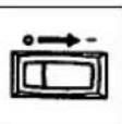
text_image
ON/STOP SwitchHOWTOSTARTYOURUNIT

WARNING: Avoidanycontactwiththe
muffler.Ahotmufflercancauseseriousburns.
STARTINGACOLDENGINE (ora warmengineafterrunningoutoffuel)

text_image
StartingposiNOTE: Thethrottlelock-outisdesignedto preventunintentionaluseofthethrottletrigger. Thelock-outmustbepressedwiththe palmofyourhandasyougripthethrottlehandlebeforethetriggercanbeused.
- Setunitonaflatsurface.
- MoveON/STOPswitchtotheONposition.
- Slowlypresstheprimerbulb6times.
- MovechokelevertoFULLCHOKEposition.

text_image
PrimerBulb Choke Lever Starter Handle- Setthethrottletothestartpositionbyfirst pressing thethrottlelock--out and the throttletrigger, thenpressingthestart throttlebutton. Thenreleasethethrottle lock--outandthethrottlerigger,followed bythestarthrottlebutton. Thethrottle functionisnowactivated.
NOTE: The start throttle button should stay depressed, holding the throttle open. If not, repeat step 5. Torem the engine to die press the throttle lock-out and throttle trigger again.
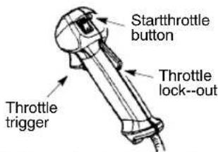
text_image
Startthrottle button Throttle lock--out Throttle trigger-
Pullstarterropehandlesharplyuntilenginesoundsasifitistryngtostart, butdo notpullropemorethan6times.
-
As soon as engines sounds as if it trying to start, move chokeleverto HALFCHOKE.
8.Pullstarterropesharplyuntilengine runs, butnomorethan6pulls.Iftheengine doesn'tstartafter6pulls(attheHALF CHOKEposition),movethechokelevento theFULLCHOKEpositionandpressthe primerbulb6times.Pullthestarterrope2 moretimes.Movethechokelevento the HALFCHOKEpositionandpullthestarter ropeuntiltheengine runs,butnomorethan 6pulls. NOTE:Ifenginestilldoesn'tstart, itisprobablyflooded.ProceedtoSTARTINGAFLOODEDENGINE.
- Oncetheenginestarts, allowittorun10 seconds, thenmovethechokeleverto RUN. Allowtheunittorunfor30 more seconds at RUN before releasing the throttle trigger. NOTE: Ifenginedies with thechokeleverinthe RUN position, move thechokelevertothe HALFCHOKE position and pulltheropeuntilengine runs, but nonmore than 6 pulls.
STARTINGAWARMENGINE
1.MoveON/STOPswitchtotheONposition.
-
Move the choke lever to the HALF CHOKEposition.
-
Set the throttle to the start position by activating the start throttle button (seestep5 under STARTINGACOLDENGINE).
-
Pullstarterropesharplyuntilengine runs, butnomorethan5pulls.
-
Allowenginetorun15seconds, thenmove thechokelevertotheRUNposition.
NOTE: Ifenginehasnotstarted, pullstarter rope5morepulls. Ifenginestilldoesnotrun, it is probably flooded.
STARTINGAFLOODEDENGINE
Floodedenginescanbestartedbyplacing thechokeleverintheRUNposition.Fully squeezeethrottletrigger;then,pulltheropeto cleartheengineofexcessfuel.Thiscouldrequirepullingthestarterhandlemanytimes dependingonhowbadlytheunitisflooded. Iftheunitstilldoesn'tstart,refertoTROUBLESHOOTINGTABLE.
OPERATINGPOSITION

text_image
ALWAYSWEAR: Hearing Protection SafetyHelmet EyeProtection Heavy, LongPants BootsCutfromyourlefttoyourright.
Whenoperatingunit,clipshoulderharness ontoclamp,standasshownandcheckforthe following:
•Weareyeprotectionandheavyclothing.
- Extendyourleftarmandholdhandlebar gripwithyourlefthand.
- Holdthrottlegripwithyourrighthandwith fingeronthrottletrigger.
- Keepunitbelowwaistlevel.
- Maintainfullweightoftoolonbothshoulders.
- Withoutbendingover, keep thebladeor trimmerheadnearandparalleltotheground andnotcrowdedintomaterialbeingcut.
OPERATINGINSTRUCTIONSFOR USEWITHTRIMMERHEAD
WARNING:Alwaysweareyeprotec-
tion.Neverleanoverthetrimmerhead.Rocks ordebriscanricochetorbethrownintoeyes andfaceandcauseblindnessorotherserious injury.
Beforetrimming, bring engine to aspeedsufficient to cut material to be trimmed.
Donotruntheengineatahigherspeedthan necessary. The cutting line will cut efficiently whentheengineisrunatlessthanfullthrottle. Atlowerspeeds,thereislessenginenoiseand vibration.Thecuttinglinewillastlongerandwill belesslikelyto"weld"ontothespool.
Alwaysreleasethethrottletriggerandallow theenginetoreturntoidlespeedwhennot cutting.
Tostopengine:
- Releasethethrottletrigger.
- Move the ON/STOP switch to the STOP position.
TRIMMERLINEADVANCE
Advancelinebytappingthebottomofthecuttingheadlightlyonthegroundwhileengineis runningatfullspeed. Themetallinelimiter bladeattachedtotheguardwillcutthelineto theproperlength.
WARNING: Useonly2,4mmdiameter
line.Othersizesoflinewillnotadvanceproperly andcancauseseriousinjury.Donotuseother materialssuchaswire,strong,rope,etc.Wire canbreakoffduringcuttingandbecomeadangerousmissilethatcancauseseriousinjury.
CUTTINGMETHODS

WARNING:Useminimumspeedand
donotcrowdthelinewhencuttingaround hardobjects(rock, gravel, fenceposts, etc.), whichcandamagethetrimmerhead,become entangledintheline,orbethrowncausinga serioushazard.
- Thetipofthelinedoesthecutting.Youwill achievethebestperformanceandminimum linewearbynotcrowdingthelineintothe cuttingarea.Therightandwrongwaysare shownbelow.
Tipo f linedoes thecutting.
Linecrowdedinto workarea.


natural_image
Illustration of a mechanical device with a lever and base, no visible text or symbolsRightWrong
- Thelinewilleasilyremovegrassandweeds fromaroundwalls,fences,treesandflower beds,butitalsocancutthetenderbarkof treesorshrubsandscarfences.
•Fortrimmingorscalping,uselessthanfull throttletoincreaselinelifeanddecreasehead wear,especially:
•Duringlightdutycutting
• Nearobjectsaroundwhichthelinecan wrapsuchassmallposts, treesorfence wire.
- Formowingorsweeping,usefullthrottlefora goodcleanjob.
TRIMMING--Holdthebottomofthetrimmer headabout8cmabovethegroundandatan angle. Allowonlythetipothelinetomake contact. Donotforcetrimmerlineintowork area.
Trimming

text_image
ning above d8cmabove ground
SCALPING - The scalping technique removes unwanted vegetationdown to the ground. Hold the bottom of the trimmer head about 8cm abovethe ground and at an angle. Allow the tip of the line to strik the ground around trees, posts, monuments, etc. This technique increases linewear.
Scalping

text_image
lpingMOWING--Yourtrimmerisidealformowing inplacesconventionallawnmowerscannot reach.Inthemowingposition,keeptheline parallel tothe ground.Avoidpressingthe headintothegroundasthiscanscalpthe groundanddamagethetool.
Mowing
natural_image
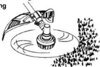
Illustration of a mechanical device with rotating components and a textured surface (no text or symbols)SWEEPING--Thefanningactionoftherotatinglinecanbeusedtoblowawayloosedebris fromanarea. Keepthelineparalleltoand abovetheareasurfaceandswingthetool fromsidetoside.
Sweeping
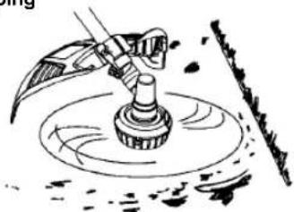
natural_image
Illustration of a mechanical device with a rotating shaft and base, no text or symbols presentOPERATING INSTRUCTIONS FOR USEWITHWEEDBLADE
- Blade Thrust is a reaction that only occurs when using ablated unit. This reaction can cause serious injury such as amputation. Carefully study this section. It is important that you understand what causes bladethrust, how you can reduce the chance of its occurring, and how you can remain in control of unit if bladethrust occurs.
• WHAT CAUSES BLADE THRUST - Blade
Thrustcanoccurwhenthespinningblade contactsanobjecthalitdoesnotcut. This contactcauseshebladetostopforaninstant and then suddenlymoveor "thrust" away fromtheobjectthatwashit.The"thrusting" reactioncanbeviolentenoughtocausethe operatortobepropelledinanydirectionand losecontroloftheunit.Theuncontrolledunit cancauseseriousinjuryifthebladecontacts theoperatororothers.
•WHENBLADETHRUSTOCCURS-
BladeThrustcanoccurwithoutwarningif thebladesnags,stalls,orbinds.This is morelikelytooccurinareaswhereitis difficulttoseethematerialbeingcut.By usingtheunitproperly,theoccurrenceof bladethrustwillbereducedandthe operatorwillbelesslikelytolosecontrol.

text_image
Warning sign depicting a traffic accident with circular hazard symbol and directional arrow- Cutonlygrass,weeds,andwoodybrushup to1cmindiameterwiththeweedblade.Do notletthebladecontactmaterialitcannotcut suchasstumps,rocks,fences,metal,etc.,or clustersofhard,woodybrushhavinga diametergreaterthan1cm.
- Keepthebladesharp. Adullblade is more likely to snag and thrust.
- Cutonlyatfullthrottle. Thebladewillhave maximumcuttingpowerandislesslikelyto bindorstall.
- "Feed"thebladedeliberatelyandnottoo rapidly. Thebladecanthrustawayifitisfed toorapidly.
- Cutonlyfromyourlefttoyourright.Cuttingon rightsideoftheshieldwillthrowdebrisaway fromtheoperator.
- Use the shoulder harness and keep a firm grip on the unit with both hands. A properly adjusted shoulder harness will support the weight of the unit, freeing your arms and hand to control and guiding the cutting motion.
-
Keepfeetcomfortablyspreadapartand bracedforapossiblesudden,rapidthrustof unit.Donotoverreach.Keepfirmfootingand balance.
-
Keepbladebelowwaistlevel; it will be easiest to maintain control of unit.
- Donotraisetheengineaboveyourwaistas thebladecancomedangerouslycloseto yourbody.
- Donotswingunitwithsuchforcethatyou areindangeroflosingyourbalance. Bringtheenginetocuttingspeedbeforeenteringthematerialtobecut.lfthebladeddoesnot turnwhenyousqueezethethrottlerigger,make sureshaftisfullyinsertedintotheengine.
Alwaysreleasethethrottletriggerandallow enginetoreturntoidlespeedwhennotcut- ting.Thebladeshouldnotturnwhiletheen- gineisrunningatidle.Ifthebladeturnsatidle, donotuseyourunit.RefertotheCARBURE- TORADJUSTMENTsectionorcontactyour authorisedservicedealer. - Maintainingoodfirmfootingwhileusingthe unit.Dothisbyplantingfeetfirmlyina comfortableapartposition.
- Cutwhileswingingtheupperpartofyour bodyfromlefttoright.
- As you move forward to the next area to cut, besuretomainyourbalanceandfooting.
RECOMMENDED CUTTING POSITION
Cutusingthe2 o'clockto4o'clock positionofthe blade

WARNING: The operator or others must not try to clear away cut material with the engineer running the bladeturning to avoid serious injury. Stop engine and blade before removing material wrapped around blade or shaft.
MAINTENANCE
Thelifespanofthemachinecanbereduced andtheriskofaccidentscanincreaseifmachinemaintenanceisnotcarriedoutcorrectly andifserviceand/orrepairsarenotcarried outprofessionally.Ifyouneedfurtherinformation,pleasecontactyournearestauthorisedservicedealer.

WARNING: Disconnectthe spark
plugbeforeperformingmaintenanceexcept forcarburetoradjustments.
CHECKFORLOOSE FASTENERSANDPARTS
- SparkPlugBoot
•AirFilter
•HousingScrews
•HandlebarScrews
•CombinationShield
CHECKFORDAMAGEDOR WORNPARTS
Contactanauthorisedservicedealerforreplacementofdamagedorwornparts.
- ON/STOPSwitch-EnsureON/STOPswitch functionsproperlybymovingtheswitchtothe STOPposition.Makesureenginestops;then restartengineandcontinue.
- Fuel Tank – Discontinue use of unit if fuel tankshowssignsofdamageorleaks.
- DebrisShield-Discontinueuseofunitif debrisshieldisdamaged.
INSPECTANDCLEANUNITAND LABELS
- After each use, inspect complete unit for looseordamagedparts. Cleantheunitand labelsusingadampclothwithamilddetergent.
•Wipeoffunitwithacleandrycloth.
CLEANAIRFILTER
Adirtyairfilterdecreasesengineperformance and increases fuel consumption and harmful emissions. Always clean after every 5 hour of operation.
- Cleanthecoverandtheareaaroundditto keepdirtfromfallingintothecarburetor chamberwhenthecoverisremoved.
- Remove parts as illustrated.
NOTE: Donotcleanfilterinpetrolorother flammablesolventtoavoidcreatingafirehazardorproducingharmfulevaporativeemissions. - Washthefilterinsoapandwater.
4.Allowfiltertodry
5.Replaceparts.

text_image
Button AirFilter AirFilterCoverREPLACESPARKPLUG
Replacethsparkplugeachyeartoensure theenginestartseasierandrunsbetter.Set sparkpluggapat0,6mm.Ignitiontimingis fixedandnonadjustable.
- Twist, then pulloff spark plug boot.
- Removesparkplugfromcylinderanddiscard.
- Replace with Champion RCJ-6Y spark plug and tightense securely with a 19mm socket wrench.
- Reinstallthesparkplugboot.
SERVICEANDADJUSTMENTS
REPLACINGTHELINE
- Pressthetabsonthesideofthetrimmer headandremovecoverandspool.
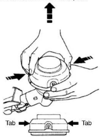
text_image
Tab Tab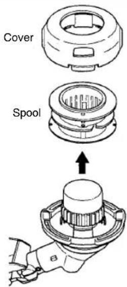
text_image
Cover Spool- Remove any remaining line.
- Cleandirtanddebrisfromallparts.Replacespoolifitiswornordamaged.
- Replace with apre-woundspool, orre-placeline using a 4,5 meters length of 2,4 mmdiameter McCullochbrandline.
WARNING: Neverusewire, rope, string, etc., which can break off and become a dangerous missile. 5. When installing newline on an existing spool, hold the spool as shown. 6. Bend the line at the midpoint and insert the bend into the slot in the center of the spool. Ensure lines naps in top position in the slot.

text_image
Slot- With your finger between the lines, wrap the lines evenly and firmly around the spoolinaclockwisedirection.
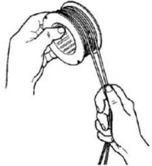
natural_image
Illustration of hands holding a rope tied with a cable, no text or symbols present- Positionthelinesintheguideslots. Guideslot Guideslot
-
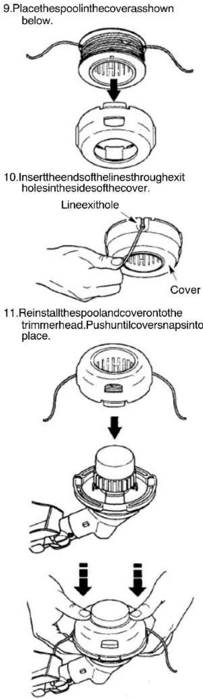
Placethespoolinthecoverasshown below.
-
Insert the endsofthelinesthroughexit holes in the sides of the recover.
-
Reinstallthespoolandcoverontothe trimmerhead.Pushuntilcoversnapsinto place.
BLADEREPLACEMENT
RefertotheASSEMBLYsectionforbladereplacementinstructionsandillustrations.
CARBURETORADJUSTMENT

WARNING: Keep others away when tingidespeed adjustments. Thetrimmer dwillbespinning during most of this procedure. Weary our protective equipment and serve all safety precautions. Aftermaking shipments, the trimmer head must not re/spinatidlespeed.
Thecarburetorhasbeencarefullysetatthe factory.Adjustmentsmaybenecessaryifyou noticeanyofthefollowingconditions:
- Enginewillnotidlewhenthethrottleisreleased.
- The trimmerhead moves/spinsatidlespeed. Make adjustments with the units supported so the cutting attachment is off the ground and will not make contact with any object. Hold the unit by hand whilerunning and making adjustments. Keep all part of your body away from the cutting attachment and muffler.
IdleSpeedAdjustment
Allowenginetoidle.Adjustspeeduntilengine runswithouttrimmerheadmovingorspinning (idlespeedtoofast)orenginestalling(idle speedtooslow).
- Turnidlespeedscrewclockwisetoin-creaseenginespeedifenginestallsordies.
- Turnidlespeedscrewcounterclockwiseto decreaseenginespeediftrimmerhead movesorspinsatidlespeed.

WARNING:Rechecktheidlespeed
aftereachadjustment. Thetrimmerhead mustnotmoveorspinatidlespeedtoavoid seriousinjurytotheoperatororothers.

text_image
IdleSpeedScrew AirFilterCoverIf you require further assistance or are unsure about performing this procedure, contact an authorised serviced dealer.
STORAGE

WARNING:Performthefollowing
stepsaftereachuse:
- Allowenginetocoolbeforestoringortransporting.
- Storeunitandfuelinawellventilatedarea wherefuelvaporscannotreachsparksor openflamesfromwaterheaters,electric motorsorswitches,furnaces,etc.
- Emptyfueltankbeforestoringortransportingtheunit.
- Storeunitandfuelwelloutofthereachof children.
- Storeunitwithallguardsinplace.Position unitsothatanysharpobjectcannotaccidentallycauseinjury.
SEASONALSTORAGE
Prepareunitforstorageatendofseasonorif itwillnotbeusedfor30daysormore. Ifyourunitistobestoredforaperiodoftime:
- Cleantheentireunitbeforelengthystorage.
•Storeinacleandryarea.
•Lightlyoilexternalmetalsurfaces.
ENGINE
- Removesparkplugandpour1teaspoonof 40:1,2-cycleengineoil(aircooled)through thesparkplugopening.Slowlypullthe starterrope8to10timestodistributeoil.
- Replacesparkplugwithnewoneofrecommendedtypeandheatrange.
- Cleanairfilter.
- Checkentireunitforloosescrews,nuts, andbolts.Replaceanydamaged,broken, orwornparts.
- Atthebeginningofthenextseason,use onlyfreshfuelhavingtheproperpetroltooil ratio.
OTHER
- Donotstorepetrolfromoneseasonto another.
-Replaceyourpetrolcanifitstartstorust.
TROUBLESHOOTINGTABLE

WARNING:Alwaysstopunitanddisconnectsparkplugbeforeperformingallofthe recommendedremediesbelowexceptremediesthatrequireoperationoftheunit.
| TROUBLECAUSEREMEDY | ||
| Enginewillnot start. | 1.ON/STOPswitchinSTOP position.2.Engineflooded.3.Fueltankempty.4.Sparkplugnotfiring.5.Fuelnotreaching carburetor.6.Carburetorrequires adjustment. | 1.MoveON/STOPswitch to ON position.2.See“StartingaFloodedEngine”in OperationSection.3.Filltankwithcorrectfuelmixture.4.Installnewsparkplug.5.Checkfordirtyfuelfilter;replace.Checkforkinkedorsplitfuelline;repairorreplace.6.Contactanaauthorisedservicedealer. |
| Enginewill notidle properly. | 1.Carburetorrequires adjustment.2.Crankshaftsealsworn.3.Compressionlow. | 1.See“CarburetorAdjustment”in ServiceandAdjustmentsSection.2.Contactanaauthorisedservicedealer.3.Contactanaauthorisedservicedealer. |
| Enginewillnot accelerate, lackspower, ordiesunder aload. | 1.Airfilterdirty.2.Sparkplugfouled.3.Carburetorrequires adjustment.4.Carbonbuild-upon muffleroutletscreen.5.Compressionlow. | 1.Cleanorreplaceairfilter.2.Cleanorreplaceplug andregap.3.Contactanaauthorisedservicedealer.4.Contactanaauthorisedservicedealer.5.Contactanaauthorisedservicedealer. |
| Engine smokes excessively. | 1.Chokepartiallyon.2.Fuelmixtureincorrect.3.Airfilterdirty.4.Carburetorrequires adjustment. | 1.Adjustchoke.2.Emptyfueltankandrefillwith correctfuelmixture.3.Cleanorreplaceairfilter.4.Contactanaauthorisedservicedealer. |
| Engineruns hot. | 1.Fuelmixtureincorrect.2.Sparkplugincorrect.3.Carburetorrequires adjustment.4.Carbonbuild-upon muffleroutletscreen. | 1.Emptyfueltankandrefillwith correctfuelmixture.2.Replacewithcorrectsparkplug.3.Contactanaauthorisedservicedealer.4.Contactanaauthorisedservicedealer. |
DECLARATIONOFCONFORMITY
ECDeclarationofConformity(OnlyappliestoEurope)
We, Husqvarna AB, SE-561 82 Huskvarna, Sweden, tel: +46-36-146500, as authorised representative in the Community, declare that the brushcutter model McCulloch Mac 250 B withserialnumbersdatingfrom2009andonwards(theyearisclearlystatedontherating plate,followedbytheserialnumber),complywiththerequirementsoftheCOUNCIL'S
DIRECTIVES:
of17May2006"relatingtomachinery"2006/42/EC;
of15December2004"relatingtoelectromagneticcompatibility"2004/108/EC,andapplicable supplements;and
of8May2000"relatingtothenoiseemissionsintheenvironment"inaccordancewithAnnex V of 2000/14/EC. For information relating to noise emissions, see Technical data section.
The following standards have been applied: ENISO12100-1/A1:2009, ENISO 12100-2/A1:2009, CISPR12:2007, EN11806:2008.
SMP, The Swedish Machinery Testing Institute, Fyrisborgsgatan3S--75450 Uppsala, Sweden, has performed voluntary type examination on behalf of Husqvarna AB. The certificate(s) are numbered: SEC/09/2027.
90

RonnieE. Goldman, Director of Engineering Authorized representative for Husqvarna AB and responsible for technical documentation
TECHNICALDATASHEET
MODEL:Mac250B
ENGINE
Cylinderdisplacement,cm 3 25
Atmaximumenginepower,rpm8000
Maximumrotationalfrequencyofthespindle10000
Enginespeedatrecommendedmaximumspindle
rotationalfrequency7400
Recommendedspeedidling,rpm3000
Maximumenginepower,measuredin
accordancewithISO8893,kW0,7
CatalyticconvertermufflerYes
IGNITIONSYSTEM
SparkplugChampionRCJ--6Y
Electrodegap,mm 0,6
FUELANDLUBRICATIONSYSTEM
Fueltankcapacity,cm 3 340
WEIGHT
Weightwithoutfuel,cuttingattachmentandguard,kg 3,7
NOISEEMISSIONS
(seeNote1)
Soundpowerlevel, measured dB(A) 110,3 Soundpowerlevel, guaranteed L _WA dB(A) 114,0
NOISELEVELS
(seeNote2)
Equivalent sound pressure level at the operators' ear, measured according to EN/ISO11806 and ISO22868, dB(A)
Equippedwithgrassblade(original) 99,0
Equippedwithtrimmerhead(original) 98,5
VIBRATIONLEVELS
(seeNote3)
Equivalent vibration levels (a _hv,eq )athandles, measured according to ENISO11806 and ISO22867, m/s ^2 Equipped with grass blade (original), left/right 4,4/6,9
Equipped with trimmer head (original), left/right 4,7/4,2
Note1: Noiseemissionsintheenvironmentmeasuredassoundpower(LWA)inconformity
with EC directive2000/14/EC. Reported soundpower level for the machine has been measured with the original cutting attachment that gives the highest level. The difference between guarantee and measured soundpower that the guarantee soundpower also includes dispersion in theme measurement result and the variations between different machines of the same model according to Directive 2000/14/EC.
Note2: Reported data for equivalents of sound pressure level for the machine has atypical statistical dispersion (standard deviation) of 1 dB(A).
Note3: Reported data for equivalent vibration level has atypical statistical dispersion (standard deviation) of 1 m/s ^2 .
| ModelMac250B(3/8LHarborshaftthread)Centreholeinblades/cutters,∅ 25,4mm | ||
| Approved accessories | Type | Cutting attachment /guard, part. no. |
| Grass blade/grass cutter | Grass (∅ 20 cm, 4-teeth) | 530 05 58 92 / 575 35 27 01 |
| Trimmer head | TNG7 (∅ 2,4 mm line) | 537 41 92-02 / 575 35 27 01 |