TTR125 - Motorcycle YAMAHA - Free user manual and instructions
Find the device manual for free TTR125 YAMAHA in PDF.

User questions about TTR125 YAMAHA
0 question about this device. Answer the ones you know or ask your own.
Ask a new question about this device
Download the instructions for your Motorcycle in PDF format for free! Find your manual TTR125 - YAMAHA and take your electronic device back in hand. On this page are published all the documents necessary for the use of your device. TTR125 by YAMAHA.
USER MANUAL TTR125 YAMAHA
OWNER'S SERVICE MANUAL
MANUEL D'ATELIER ET
DU PROPRIETAIRE
FAHRER- UND
WARTUNGS-HANDBUCH
TT-R125(N)
TT-R125LW(N)
EC010010
TT-R125(N)/TT-R125LW(N)
OWNER'S SERVICE MANUAL
2000 by Yamaha Motor Co., Ltd.
1st Edition, June 2000
All rights reserved. Any reprinting or unauthorized use without the written permission of Yamaha Motor Co., Ltd.
is expressly prohibited.
Printed in Japan
TT-R125(N)/TT-R125LW(N)
MANUEL D'ATELIER ET DU PROPRIÉTAIRE
2000 Yamaha Motor Co., Ltd.
Congratulations on your purchase of a Yamaha TT-R125(N)/TT-R125LW(N). This model is the culmination of Yamaha's vast experience in the production of pacesetting racing machines. It represents the highest grade of craftsmanship and reliability that have made Yamaha a leader.
This manual explains operation, inspection, basic maintenance and tuning of your machine. If you have any questions about this manual or your machine, please contact your Yamaha dealer.
NOTE:
As improvements are made on this model, some data in this manual may become outdated. If you have any questions, please consult your Yamaha dealer.
WARNING
- READ THIS MANUAL CAREFULLY FOR INSTRUCTIONS ON HOW TO PROPERLY OPERATE THIS MACHINE.
- ADULT INSTRUCTION AND SUPERVISION ARE REQUIRED.
- WEIGHT OF THE RIDER SHOULD NOT EXCEED 68 kg (150 lb). (TT-R125 ONLY)
- ALWAYS WEAR A HELMET AND SUITABLE PROTECTIVE CLOTHING WHEN RIDING.
• DO NOT TOUCH ANY MOVING PARTS OR HEATED AREAS.
• ALWAYS PERFORM PRE-OPERATION CHECKS. REFER TO PAGE 3-3. - THIS MACHINE IS DESIGNED TO CARRY THE OPERATOR ONLY. NO PASSENGERS.
- THIS MACHINE IS DESIGNED OFF-ROAD USE ONLY. IT IS NOT SUITABLE FOR ON-ROAD USE.
INTRODUCTION
This machine is designed for off-road use only by young operators under adult instruction and supervision. It is illegal for this machine to be operated on any public street, road, or highway.
Off-road use on public lands may be illegal.
Please check local regulations before riding.
SAFETY INFORMATION
1. GASOLINE IS HIGHLY FLAMMABLE:
* Always turn off the engine when refueling.
* Take care not to spill on the engine or exhaust pipe/muffler, when refueling.
* Never refuel while smoking or in the vicinity of an open flame.
-
If you should swallow some gasoline or inhale a lot of gasoline vapor, or allow some gasoline to get in your eye(s), see your doctor immediately. If any gasoline spills on your skin or clothing, immediately wash it with soap and water, and change your clothes.
-
Always turn off the engine before leaving the machine unattended. When parking the machine, note the following:
* The engine and exhaust pipe(s)/muffler(s) may be hot. Park the machine in a place where pedestrians or children are not likely to touch the machine.
* Do not park the machine on a slope or soft ground; the machine may overturn.
REMARQUE IMPORTANTE
natural_image
Illustration of a motorcyclist crossing a circular obstacle with a dog nearby (no text or symbols)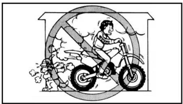
natural_image
Illustration of a person riding a bicycle under a circular barrier with smoke and clouds (no text or symbols)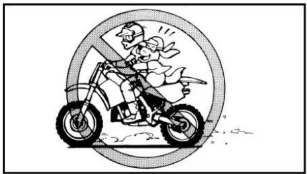
natural_image
Cartoon illustration of a person riding a motorcycle inside a circular frame (no text or symbols)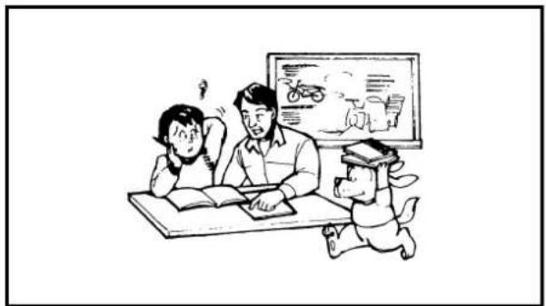
natural_image
Illustration of a classroom scene with teacher, students, and a dog (no text or symbols present)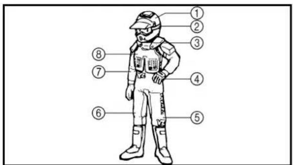
text_image
Labeled diagram of a person wearing a helmet and safety gear, with numbered parts for identification.SAFETY INFORMATION
-
Do not ride it on the street.
-
Do not run the engine inside a building.
-
This is a one-seater motorbike. Do not give any person a ride.
-
Let's learn how to ride properly. Ask your parents for any question.
-
When riding the machine, be sure to wear the protective apparel as illustrated.
① Helmet
② Goggles
③ Mouth guard
④ Gloves
⑤ Boots
⑥ Motocross pants
⑦ Long sleeved trainer
⑧ Protector
⚠ INFORMATION DE SECURITE
natural_image
Line drawing of a boy and a man standing beside a motorcycle, no text or symbols present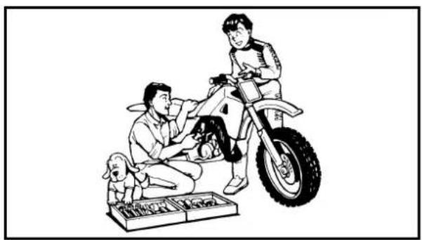
natural_image
Illustration of a man and child on a motorcycle with a dog nearby (no text or symbols)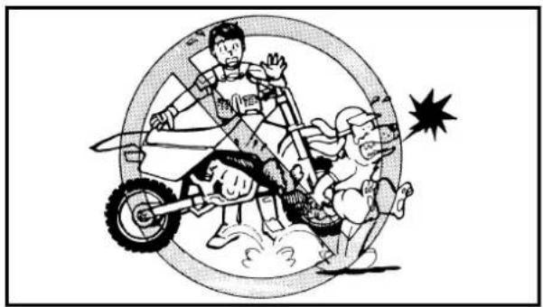
natural_image
Cartoon illustration of a group of people riding a wheeled cart inside a circular frame, with a starburst symbol in the corner (no text or symbols present)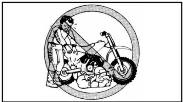
natural_image
Illustration of a person using a bicycle to interact with children, enclosed in a circular frame (no text or symbols)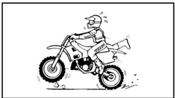
natural_image
Cartoon illustration of a motorcyclist riding a large tire, kicking up dust (no text or symbols)This manual will provide you with a good basic understanding of features, operation, and basic maintenance and inspection items of this machine. Please read this manual carefully and completely before operating your new machine. If you have any questions regarding the operation or maintenance of your machine, please consult your Yamaha dealer.
NOTE:
This manual should be considered a permanent part of this machine and should remain with it even if the machine is subsequently sold.
EC060000
NOTICE
Some data in this manual may become outdated due to improvements made to this model in the future. If there is any question you have regarding this manual or your machine, please consult your Yamaha dealer.
AVIS AU NOUVEAU PRO- PRIÉTAIRE
HOW TO USE THIS MANUAL
EC081000
PARTICULARLY IMPORTANT INFORMATION

The Safety Alert Symbol means ATTENTION! BECOME ALERT! YOUR SAFETY IS INVOLVED!

WARNING
Failure to follow WARNING instructions could result in severe injury or death to the machine operator, a bystander, or a person inspecting or repairing the machine.
CAUTION:
A CAUTION indicates special precautions that must be taken to avoid damage to the machine.
NOTE:
A NOTE provides key information to make procedures easier or clearer.
text_image
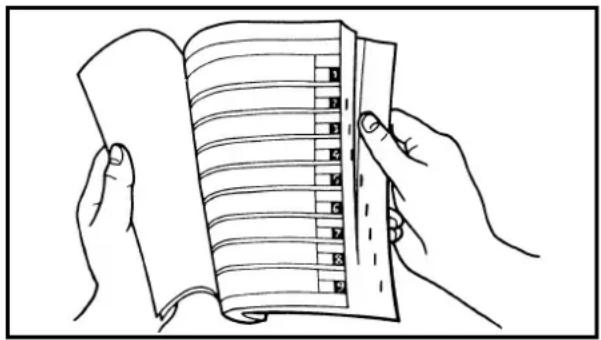
Line drawing showing hands holding an open notebook with numbered pages arranged verticallyFINDING THE REQUIRED PAGE
- This manual consists of six chapters; "General Information", "Specifications", "Regular inspection and adjustments", "Engine", "Chassis" and "Electrical".
- The table of contents is at the beginning of the manual. Look over the general layout of the book before finding then required chapter and item.
Bend the book at its edge, as shown, to find the required fore edge symbol mark and go to a page for required item and description.
COMMENT UTILISER CE MANUEL
INFORMATIONS IMPORTANTES

All of the procedures in this manual are organized in a sequential, step-by-step format. The information has been complied to provide the mechanic with an easy to read, handy reference that contains comprehensive explanations of all disassembly, repair, assembly, and inspection operations.
In this revised format, the condition of a faulty component will precede an arrow symbol and the course of action required will follow the symbol, e.g.
- Bearings
Pitting/damage → Replace.
EC084002
HOW TO READ DESCRIPTIONS
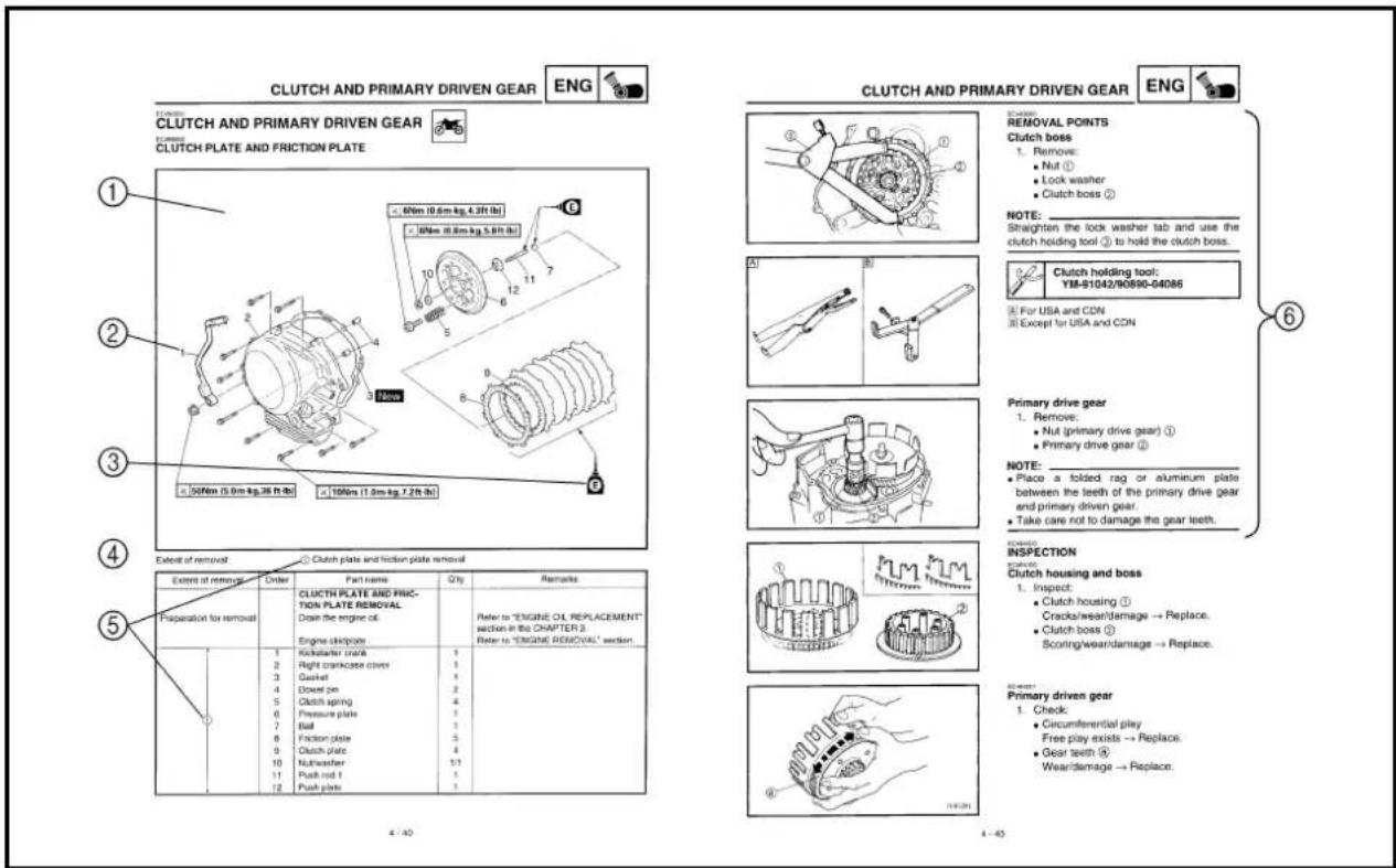
To help identify parts and clarify procedure steps, there are exploded diagrams at the start of each removal and disassembly section.
-
An easy-to-see exploded diagram ① is provided for removal and disassembly jobs.
-
Numbers ② are given in the order of the jobs in the exploded diagram. A number that is enclosed by a circle indicates a disassembly step.
-
An explanation of jobs and notes is presented in an easy-to-read way by the use of symbol marks ③. The meanings of the symbol marks are given on the next page.
-
A job instruction chart ④ accompanies the exploded diagram, providing the order of jobs, names of parts, notes in jobs, etc.
-
Extent of removal ⑤ is provided in the job instruction chart to save the trouble of an unnecessary removal job.
-
For jobs requiring more information, the step-by-step format supplements ⑥ are given in addition to the exploded diagram and job instruction chart.
text_image
CLUTCH AND PRIMARY DRIVEN GEAR ENG CLUTCH CLUTCH AND PRIMARY DRIVEN GEAR CLUTCH PLATE AND FRICTION PLATE ① ② ③ ④ ⑤ Extent of removal ⑥ Clutch plate and friction plate removal Extent of removal Order Part name Qty Remarks CLUTCH PLATE AND FRICTION PLATE REMOVAL Drain the engine oil. Engine cluckgate 1 2 3 4 5 6 7 8 9 10 11 12 13 14 15 16 17 18 19 20 21 22 23 24 25 26 27 28 29 30 31 32 33 34 35 36 37 38 39 40 41 42 43 44 45 46 47 48 49 50 51 52 53 54 55 56 57 58 59 60 61 62 63 64 65 66 67 68 69 70 71 72 73 74 75 76 77 78 79 80 81 82 83 84 85 86 87 88 89 90 91 92 93 94 95 96 97 98 99 100m (1.0m kg, 3ft lb) 100m (1.0m kg, 2ft lb) 100m (1.0m kg, 2ft lb) ① Remove: ● Nut ① ● Lock washer ● Clutch boss ② NOTE: Straighten the lock washer tab and use the clutch holding tool ③ to hold the clutch boss. A) B) Clutch holding tool: YM-51042/90890-04086 For USA and CDN Except for USA and CDN Primary drive gear: 1. Remove: ● Nut (primary drive gear) ④ ● Primary drive gear ⑤ NOTE: ● Place a folded rag or aluminum plate between the teeth of the primary drive gear and primary driven gear. ● Take care not to damage the gear teeth. INSPECTION: Clutch housing and boss: 1. Inspect: ● Clutch housing ① Cracks/wear/damage → Replace. ● Clutch boss ② Scoring/wear/damage → Replace. Primary driven gear: 1. Check: ● Circumferential play Free play exists → Replace. ● Gear teeth ④ Wear/damage → Replace.FORMAT DU MANUEL
ILLUSTRATED SYMBOLS (Refer to the illustration)
Illustrated symbols ① to ⑥ are designed as thumb tabs to indicate the chapter's number and content.
① General information
② Specifications
③ Regular inspection and adjustments
④ Engine
⑤ Chassis
⑥ Electrical
Illustrated symbols ⑦ to ⑭ are used to identify the specifications appearing in the text.
⑦ With engine mounted
⑧ Special tool
⑨ Filling fluid
⑩ Lubricant
⑪ Tightening
⑫ Specified value, Service limit
⑬ Engine speed
⑭ Resistance (Ω), Voltage (V), Electric current (A)
Illustrated symbols ⑮ to ⑱ in the exploded diagrams indicate grade of lubricant and location of lubrication point.
⑮ Apply engine oil
⑯ Apply molybdenum disulfide oil
⑰ Apply lightweight lithium-soap base grease
⑱ Apply molybdenum disulfide grease
Illustrated symbols ⑲ to ⑳ in the exploded diagrams indicate where to apply a locking agent and when to install new parts.
⑲ Apply locking agent (LOCTIT®)
⑳ Use new one
REGULAR INSPECTION AND ADJUSTMENT
ENGINE
CHASSIS
ELECTRICAL
INDEX
| RENSEIGNEMENTS GÉNÉRAUX |
| CARACTÉRISTI-QUES |
| CONTRÔLES ET RÉGLAGES PÉRIODIQUES |
| MOTEUR |
| PARTIE CYCLE |
| PARTIE ÉLECTRIQUE |
INDEX
CHECKING OF CONNECTION 1-5
SPECIAL TOOLS 1-6
CONTROL FUNCTIONS 1-9
FUEL 1-12
STARTING AND BREAK-IN 1-13
TORQUE-CHECK POINTS 1-15
TT-R125 1-15
TT-R125LW 1-16
CLEANING AND STORAGE 1-17
CHAPTER 2
SPECIFICATIONS
GENERAL SPECIFICATIONS.... 2-1
TT-R125 2-1
TT-R125LW 2-4
MAINTENANCE SPECIFICATIONS ..... 2-7
ENGINE 2-7
CHASSIS 2-15
TT-R125 2-15
TT-R125LW 2-19
ELECTRICAL 2-23
GENERAL TORQUE
SPECIFICATIONS 2-24
DEFINITION OF UNITS 2-24
CABLE ROUTING DIAGRAM 2-25
CHAPTER 3
REGULAR INSPECTION AND
ADJUSTMENTS
MAINTENANCE INTERVALS 3-1
KICK AXLE AND SHIFT SHAFT 4-53
CDI MAGNETO 4-58
ENGINE REMOVAL 4-61
CRANKCASE, CRANKSHAFT
AND BALANCER 4-65
TRANSMISSION, SHIFT CAM
AND SHIFT FORK 4-73
CHAPTER 5 CHASSIS
FREIN ARRIÈRE....5-24
FOURCHE AVANT....5-32
GUIDON 5-41
DIRECTION....5-49
BRAS OSCILLANT....5-55
COMBINÉ RESSORT-
AMORTISSEUR ARRIÈRE....5-62
CHAPITRE 6 PARTIE ÉLECTRIQUE
ÉQUIPEMENT ÉLECTRIQUE ET SCHÉMA
DE CÂBLAGE....6-1
SYSTÈME D'ALLUMAGE....6-2
KAPITEL 4 MOTOR
SITZ, KRAFTSTOFFTANK UND
SEITENDECKEL 4-1
SCHALLDÄMPFER 4-2
VERGASER 4-3
ZYLINDERKOPF 4-12
NOCKENWELLE UND KIPPHEBEL ..... 4-20
VENTILE UND VENTILFEDERN 4-24
ZYLINDER UND KOLBEN 4-32
KUPPLUNG UND
PRIMÄRABTRIEBSZAHNRAD 4-40
ÖLPUMPE 4-49
KICKSTARTERWELLE UND
SCHALTWELLE 4-53
LICHTMASCHINENROTOR 4-58
MOTOR AUSBAUEN 4-61
KURBELGEHÄUSE,KURBELWELLE
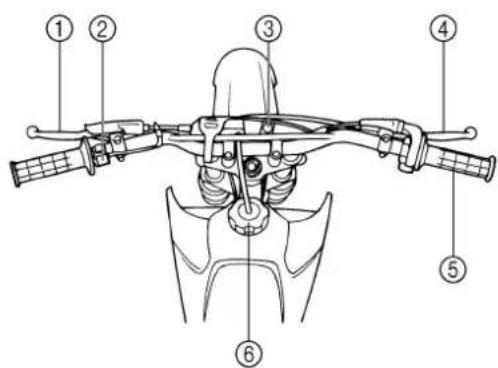
① Clutch lever
② Engine stop switch
③ Starter knob
④ Front brake lever
⑤ Throttle grip
⑥ Fuel tank cap
⑦ Air filter
⑧ Kickstarter crank
⑨ Fuel tank
⑩ Dipstick
⑪ Rear brake pedal
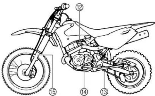
⑫ Fuel cock
⑬ Drive chain
⑭ Shift pedal
⑮ Front fork
NOTE:
- The machine you have purchased may differ slightly from those shown in the following.
- Designs and specifications are subject to change without notice.
text_image
Technical diagram of a mechanical device with numbered parts for identification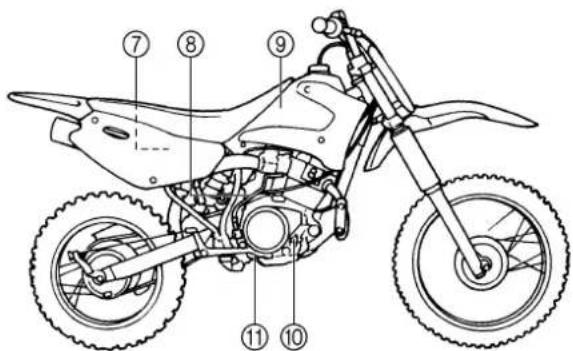
text_image
Technical diagram of a four-wheeled motorcycle with numbered components for identification*The illustration shows the TT-R125LW.
text_image
Technical diagram of a DTR motorcycle with numbered parts labeled for identification.RENSEIGNEMENTS
GÉNÉRAUX
DESCRIPTION
There are two significant reasons for knowing the serial number of your machine:
-
When ordering parts, you can give the number to your Yamaha dealer for positive identification of the model you own.
-
If your machine is stolen, the authorities will need the number to search for and identify your machine.
EC121001
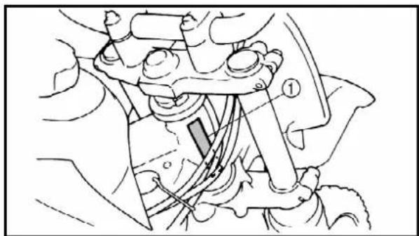
VEHICLE IDENTIFICATION NUMBER
The vehicle identification number ① is stamped on the right of the steering head pipe.
natural_image
Mechanical assembly diagram showing a clamping device with no visible text or symbols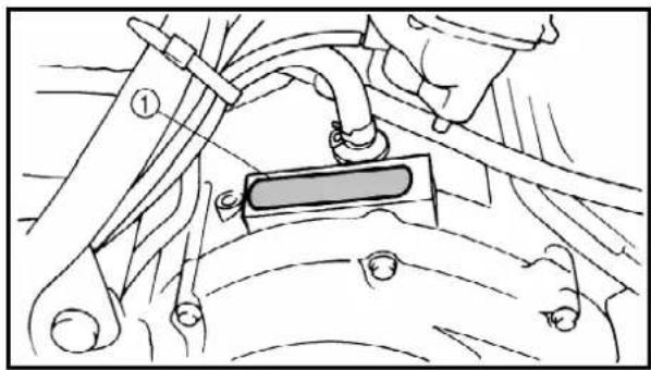
natural_image
Mechanical assembly diagram showing a lever and belt mechanism (no text or labels)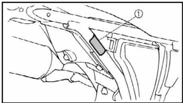
text_image
Technical diagram of a mechanical assembly with labeled component ①EC123001
ENGINE SERIAL NUMBER
The engine serial number ① is stamped into the elevated part of the right-side of the engine.
EC124000
MODEL LABEL
The model label ① is affixed to the frame under the rider's seat. This information will be needed to order spare parts.
IDENTIFICATION DE LA MACHINE
natural_image
Cartoon illustration of a person washing a motorcycle with buckets and a bucket (no text or symbols)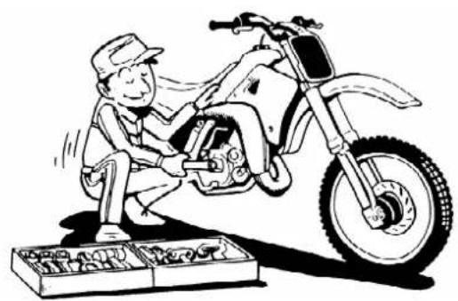
natural_image
Cartoon illustration of a mechanic working on a motorcycle with tools, no text or symbols present
natural_image
Cartoon illustration of a person using a power tool to interact with a device (no text or symbols present)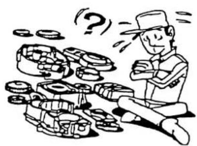
natural_image
Cartoon illustration of a man sitting on the floor surrounded by stacks of coins and question marks (no text or symbols)EC130000 IMPORTANT INFORMATION
EC131002 PREPARATION FOR REMOVAL AND DISASSEMBLY
-
Remove all dirt, mud, dust, and foreign material before removal and disassembly.
-
Use proper tools and cleaning equipment. Refer to "SPECIAL TOOLS" section.
-
When disassembling the machine, keep mated parts together. They include gears, cylinders, pistons, and other mated parts that have been "mated" through normal wear. Mated parts must be reused as an assembly or replaced.
-
During the machine disassembly, clean all parts and place them in trays in the order of disassembly. This will speed up assembly time and help assure that all parts are correctly reinstalled.
-
Keep away from fire.
EC132000 ALL REPLACEMENT PARTS
- We recommend to use Yamaha genuine parts for all replacements. Use oil and/or grease recommended by Yamaha for assembly and adjustment.
INFORMATIONS IMPORTANTES PRÉPARATION À LA DÉPOSE ET AU DÉMONTAGE
GASKETS, OIL SEALS AND O-RINGS
-
All gaskets, oil seals, and O-rings should be replaced when an engine is overhauled. All gasket surfaces, oil seal lips, and O-rings must be cleaned.
-
Properly oil all mating parts and bearings during reassembly. Apply grease to the oil seal lips.
text_image
Technical diagram showing two bolts connected to a bolt with a numbered connection point labeled 1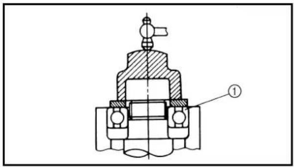
text_image
Technical diagram of a mechanical valve assembly with labeled component ①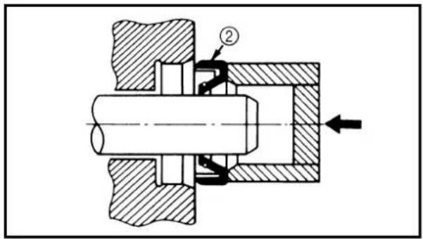
text_image
Technical mechanical diagram showing a cross-sectional view of a bearing assembly with labeled component ② and directional arrow.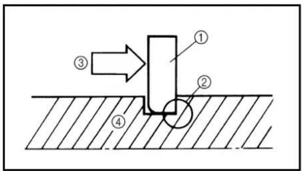
text_image
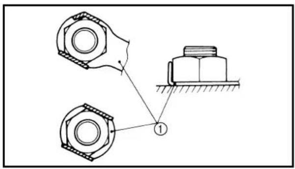
Technical diagram showing a mechanical or structural component with numbered parts and directional arrow indicating motionEC134000
LOCK WASHERS/PLATES AND COTTER PINS
- All lock washers/plates ① and cotter pins must be replaced when they are removed. Lock tab(s) should be bent along the bolt or nut flat(s) after the bolt or nut has been properly tightened.
EC135001
BEARINGS AND OIL SEALS
- Install the bearing(s) ① and oil seal(s) ② with their manufacturer's marks or numbers facing outward. (In other words, the stamped letters must be on the side exposed to view.) When installing oil seal(s), apply a light coating of lightweight lithium base grease to the seal lip(s). Oil the bearings liberally when installing.
CAUTION:
Do not use compressed air to spin the bearings dry. This causes damage to the bearing surfaces.
EC136000
CIRCLIPS
- All circlips should be inspected carefully before reassembly. Always replace piston pin clips after one use. Replace distorted circlips. When installing a circlip ①, make sure that the sharp-edged corner ② is positioned opposite to the thrust ③ it receives. See the sectional view.
④ Shaft
JOINTS, BAGUES D'ÉTANCHÉITÉ ET JOINTS TORIQUES
natural_image
Two-panel line drawing showing a hand holding a tool, with no text or symbols present.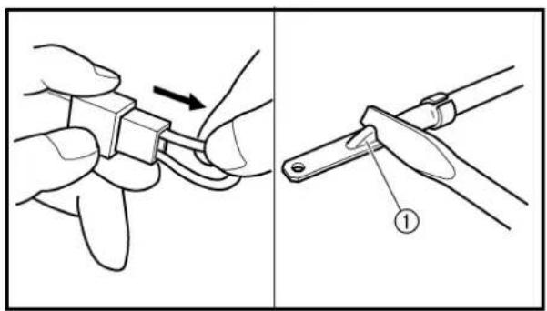
text_image
Technical diagram showing two-step assembly steps of a mechanical component, with labeled parts ① and directional arrow indicating motion.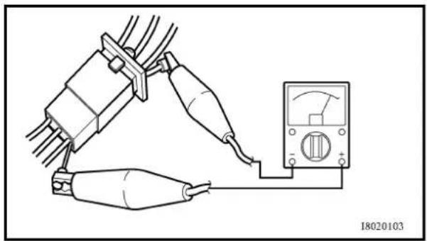
natural_image
Pure electrical circuit lines without any symbols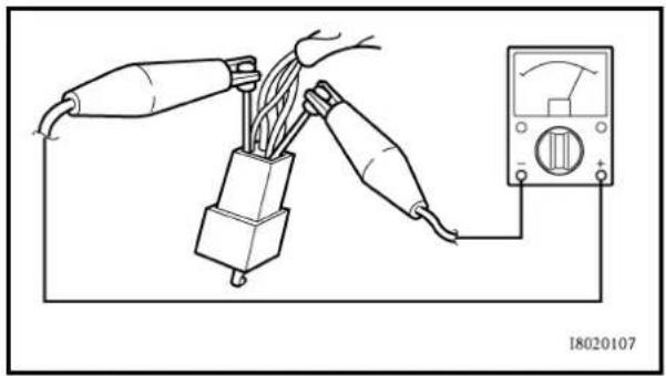
natural_image
Diagram of a hand connecting two cables to a plug and connected to an analog multimeter (no text or symbols present)EC1C0000
CHECKING OF CONNECTION
Dealing with stains, rust, moisture, etc. on the connector.
- Disconnect:
- Connector
-
Dry each terminal with an air bower.
-
Connect and disconnect the connector two or three times.
-
Pull the lead to check that it will not come off.
-
If the terminal comes off, bend up the pin ① and reinsert the terminal into the connector.
-
Connect:
- Connector
NOTE:
The two connectors "click" together.
- Check for continuity with a tester.
NOTE:
- If there in no continuity, clean the terminals.
- Be sure to perform the steps 1 to 7 listed above when checking the wireharness.
- For a field remedy, use a contact revitalizer available on the market.
- Use the tester on the connector as shown.
VÉRIFICATION DES CONNEXIONS
The proper special tools are necessary for complete and accurate tune-up and assembly. Using the correct special tool will help prevent damage caused by the use of improper tools or improvised techniques. The shape and part number used for the special tool differ by country, so two types are provided. Refer to the list provided to avoid errors when placing an order.
NOTE:
- For U.S.A. and CDN, use part number starting with "YM-", "YU-" or "YS-".
- For others, use part number starting with "90890-".
| Part number Tool name/How to use Illustration | |||
| YU-1083-A90890-0108490890-01085 | Small slide hammer setWeightSlide hammer boltThese tools are used when removing or installing the rocker arm shafts. | YU-1083-A 90890-01084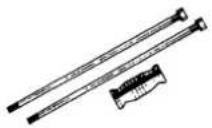 | 90890-01085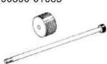 |
| YU-1135-A, 90890-01135 Crankcase separating toolThese tools are used to split the crankcase as well as remove the crankshaft from either case. | YU-1135-A 90890-01135 | 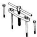 | |
| YU-3097, 90890-01252YU-1256 | Dial gauge & stand setStandThese tools are used to check each part for runout or bend. | YU-3097YU-1251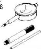 | 90890-01252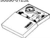 |
| YU-90050, 90890-01274YU-90050, 90890-01275YU-90063, 90890-01278YU-91044, 90890-04081 | Crankcase installing toolCrankshaft installer potCrankshaft installer boltAdaptorSpacer (crankshaft installer)These tools are used to install the crankshaft. | YU-90050YU-91044YU-9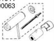 | 90890-0127490890-0127590890-90890-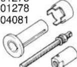 |
| YM-01326, 90890-01326YM-1300, 90890-01294 | T-handleDamper rod holderThese tools are used for holding the damper rod holder when removing or installing the damper rod holder. | YM-01326YM-1300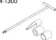 | 90890-01326$0000-01004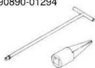 |
| YU-1304, 90890-01304 Piston pin puller setThis tool is used to remove the piston pin. | YU-1304 90890-01304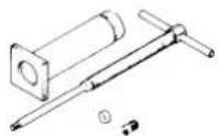 | 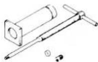 | |
| YM-8035, 90890-01311 Tappet adjusting toolThis tool is necessary for adjusting valve clearance. | YM-8035 90890-01311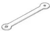 | 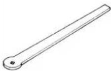 | |
| YM-1312-A, 90890-01312 Fuel level gaugeThis gauge is used to measure the fuel level in the float chamber. | YM-1312-A 90890-01312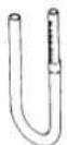 | 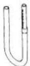 | |
| YU-33270-B, 90890-01362 Flywheel pullerThis tool is used to remove the rotor. | YU-33270-B 90890-01362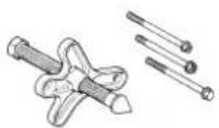 | 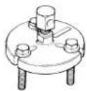 | |
| YM-33963, 90890-01367YM-33281, 90890-01400 | Fork seal driver weightFork seal driver attachmentThese tools are used to installing the fork oil seal. | YM-33963YM-33281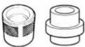 | 90890-0136790890-01400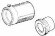 |
| YU-33975, 90890-01403 Steering nut wrenchThis tool is used when tighten the steering ring nut to specification. | YU-33975 90890-01403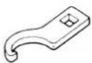 |  | |
| YS-1880-A, 90890-01701 Sheave holderThis tool is used for when loosening or tightening the flywheel magneto securing nut. | YS-1880-A 90890-01701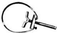 | 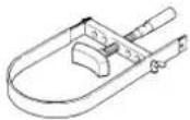 | |
| YU-3112-C, 90890-03112 Pocket testerUse this tool to inspect the coil resistance, output voltage and amperage. | YU-3112-C 90890-03112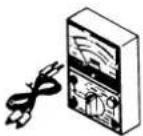 |  | |
| YU-8036-B 90890-03113 | Inductive tachometerEngine tachometerThis tool is needed for observing engine rpm. | YU-8036-B 90890-03113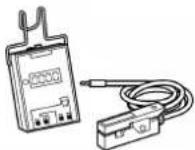 | 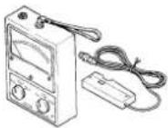 |
| YM-4019, 90890-04019 Valve spring compressorThis tool is needed to remove and install the valve assemblies. | YM-4019 90890-04019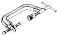 | 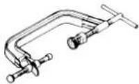 | |
| YM-91042, 90890-04086 Clutch holding toolThis tool is used to hold the clutch when removing or installing the clutch boss securing nut. | YM-91042 90890-04086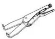 | 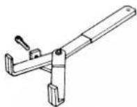 | |
| YM-4097, 90890-04097YM-4098, 90890-04098YM-04099, 90890-04099 | Valve guide removerValve guide installerValve guide reamerThese tools are needed to rebore the new valve guide. | YM-4097YM-4098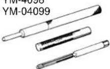 | 90890-0409790890-04098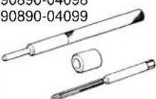 |
| YM-3448790890-06754 | Dynamic spark testerIgnition checkerThis instrument is necessary for checking the ignition system components. | YM-34487 90890-06754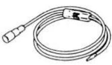 | 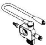 |
| ACC-QUICK-GS-KT90890-85505 | Quick gasket®YAMAHA Bond No.1215This sealant (Bond) is used for crankcase mating surface, etc. | ACC-QUICK-GS-KT 90890-85505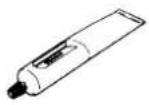 |  |
OUTILS SPÉCIAUX
natural_image
Technical line drawing of a mechanical assembly with a numbered component (1), no visible text or symbols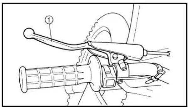
natural_image
Technical line drawing of a bicycle steering wheel and drivetrain mechanism (no text or symbols)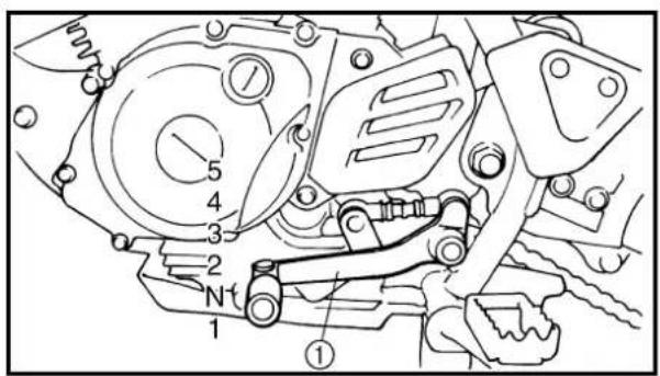
text_image
Technical diagram of a mechanical assembly with numbered components and labeled parts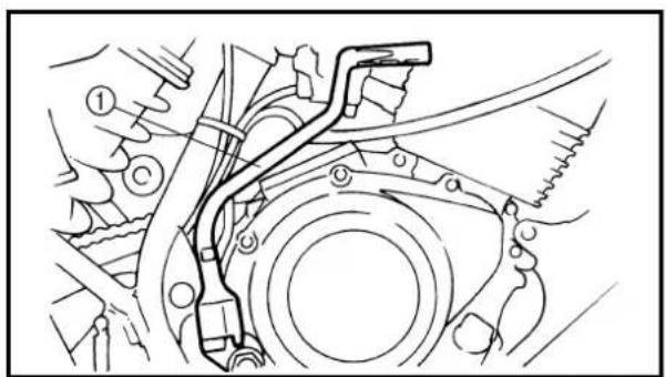
natural_image
Technical line drawing of a mechanical assembly with no visible text or symbols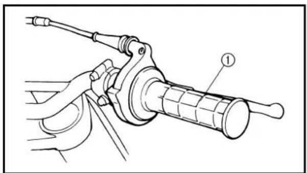
natural_image
Mechanical assembly diagram showing a lever mechanism with labeled component (1), no text or symbols presentEC150000
CONTROL FUNCTIONS
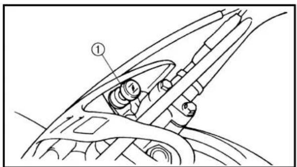
ENGINE STOP SWITCH
The engine stop switch ① is located on the left handlebar. Continue pushing the engine stop switch till the engine comes to a stop.
EC152000
CLUTCH LEVER
The clutch lever ① is located on the left handlebar; it disengages or engages the clutch. Pull the clutch lever to the handlebar to disengage the clutch, and release the lever to engage the clutch. The lever should be pulled rapidly and released slowly for smooth starts.
EC153000
SHIFT PEDAL
The gear ratios of the constant-mesh 5 speed transmission are ideally spaced. The gears can be shifted by using the shift pedal ① on the left side of the engine.
KICKSTARTER CRANK

WARNING
Before starting the engine, be sure to shift the transmission into neutral.
Rotate the kickstarter crank ① away from the engine. Push the starter down lightly with your foot until the gears engage, then kick smoothly and forcefully to start the engine.
EC155001
THROTTLE GRIP
The throttle grip ① is located on the right handlebar; it accelerates or decelerates the engine. For acceleration, turn the grip toward you; for deceleration, turn it away from you.
FONCTIONS DES COMMANDES COUPE-CIRCUIT DU MOTEUR
natural_image
Mechanical assembly diagram showing a lever mechanism with no visible text or symbols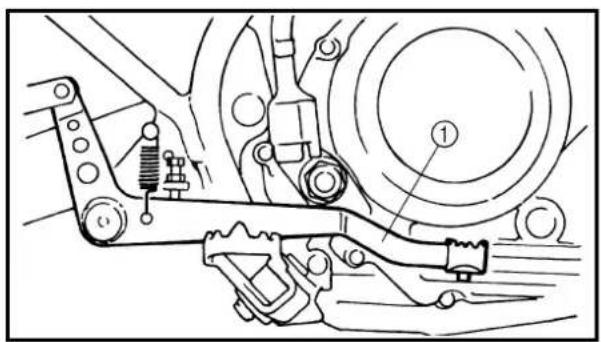
text_image
Technical diagram of a vehicle suspension system with labeled components and structural details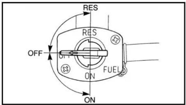
text_image
RES RES OFF ON FUEL ONEC156000
FRONT BRAKE LEVER
The front brake lever ① is located on the right handlebar. Pull it toward the handlebar to activate the front brake.
EC157000
REAR BRAKE PEDAL
The rear brake pedal ① is located on the right side of the machine. Press down on the brake pedal to activate the rear brake.
EC158010
FUEL COCK
The fuel cock supplies fuel from the tank to carburetor while filtering the fuel. The fuel cock has the three positions:
OFF: With the lever in this position, fuel will not flow. Always return the lever to this position when the engine is not running.
ON: With the lever in this position, fuel flows to the carburetor. Normal riding is done with the lever in this position.
RES: This indicates reserve. If you run out of fuel while riding, move the lever to this position. FILL THE TANK AT THE FIRST OPPORTUNITY. BE SURE TO SET THE LEVER TO "ON" AFTER REFUELING.
text_image
Technical diagram of a car dashboard with labeled parts, showing structural components and directional arrows.EC159000
STARTER KNOB (CHOKE)
When cold, the engine requires a richer air-fuel mixture for starting. A separate starter circuit, which is controlled by the starter knob ①, supplies this mixture. Pull the starter knob out to open the circuit for starting. When the engine has warmed up, push it in to close the circuit.
LEVIER DE FREIN AVANT
natural_image
Mechanical assembly diagram showing a lever and component (no text or symbols)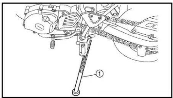
text_image
Technical diagram of a mechanical assembly with labeled component ①FUEL TANK CAP
Remove the fuel tank cap ① by turning counterclockwise.
WARNING
Do not overfill the fuel tank. Avoid spilling fuel on the hot engine.
SIDESTAND
This sidestand ① is used to support only the machine when standing or transporting it.
WARNING
- Never apply additional force to the side-stand.
- Hold up the sidestand before starting out.
FONCTIONS DES COMMANDES ARMATUREN UND DEREN FUNKTION

BOUCHON DE RÉSERVOIR DE CARBURANT
text_image
Diagram of a water tank with labeled components and flow direction indicatorFUEL
Use regular gasoline. Always use fresh, name brand gasoline.
WARNING
Do not overfill the fuel tank. Avoid spilling fuel on the hot engine. Do not fill the fuel tank above the bottom of the filler tube ① as shown in the illustration or it may overflow when the fuel heats up later and expands.
① Fuel level

Recommended fuel:
For USA:
Unleaded fuel
For CDN and EUROPE:
Regular unleaded gasoline
For AUS:
Unleaded fuel only
For NZ:
Regular gasoline
Fuel tank capacity:
Total:
6.6 L (1.45 Imp gal, 1.74 US gal)
Reserve:
1.9 L (0.42 Imp gal, 0.5 US gal)
CARBURANT
Before starting the machine, perform the checks in the pre-operation check list.

WARNING
Never start or run the engine in a closed area. The exhaust fumes are poisonous; they can cause loss of consciousness and death in a very short time. Always operate the machine in a well-ventilated area.
STARTING A COLD ENGINE
- Shift the transmission into neutral.
- Turn the fuel cock to "ON" and full open the starter knob (CHOKE).
- With the throttle completely closed start the engine by kicking the kickstarter crank forcefully with firm stroke.
- Run the engine at idle or slightly higher until it warms up: this usually takes about one or two minutes.
- The engine is warmed up when it responds normally to the throttle with the starter knob (CHOKE) turned off.
CAUTION:
Do not warm up the engine for extended periods.
EC193001
STARTING A WARM ENGINE
Do not operate the starter knob (CHOKE). Open the throttle slightly and start the engine by kicking the kickstater forcefully with firm stroke.
CAUTION:
Observe the following break-in procedures during initial operation to ensure optimum performance and avoid engine damage.
DÉMARRAGE ET RODAGE
ATTENTION:
Break-in is important to better fit the moving and sliding parts as well as the installed parts. It is also important to accustom the rider to the machine better.
Avoid full-throttle run on a new machine for the first 5 hours.
After the trial run, check for loose parts, oil leakage and other problems.
Make full inspection and adjustment especially of slack cables and drive chain and loose spokes.
CAUTION:
After the break-in or before each ride, you must check the entire machine for loose fittings and fasteners as per "TORQUE-CHECK POINTS".
Tighten all such fasteners as required.
BREAKING IN AFTER REPLACEMENT
After a part is replaced with a new one, it is necessary to break it in as in a new machine.
This is required especially when the following engine-related parts are replaced.
• Cylinder
• Piston
- Piston ring
• Valve
• Camshaft
• Crankshaft
- Clutch
• Transmission gear
- Shift fork
* For warming up and inspection during break-in, refer to "GENERAL INSPECTION AND MAINTENANCE" and if there is any problem, stop the engine immediately and check.
RODAGE
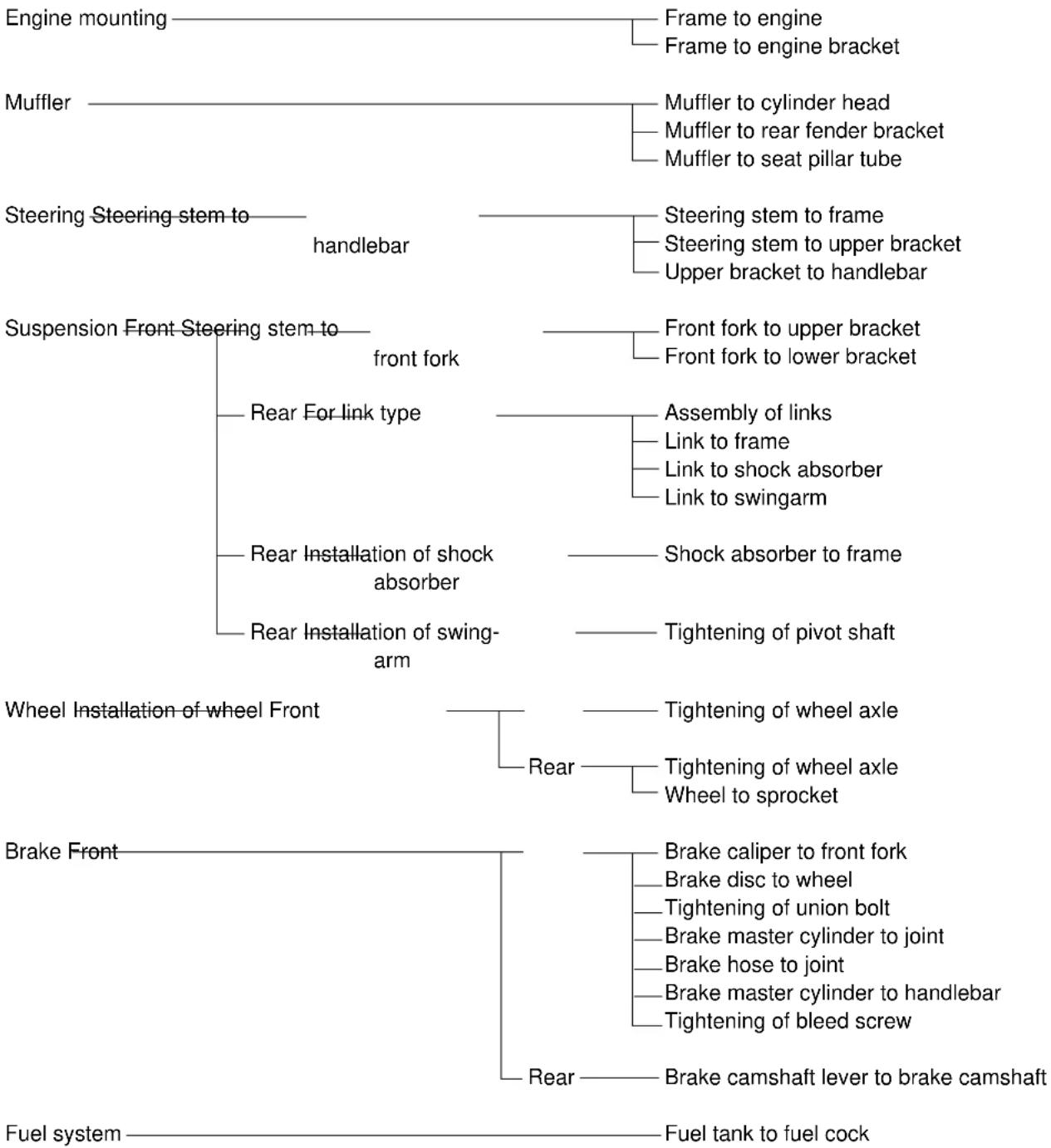
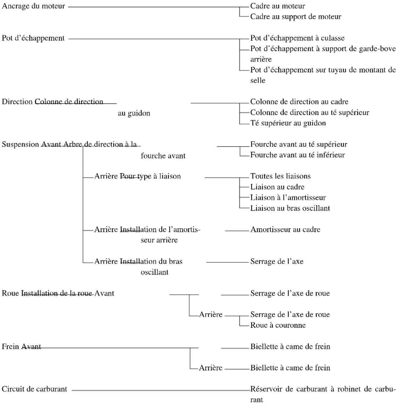
flowchart
graph TD
    A["Engine mounting"] --> B["Frame to engine"]
    A --> C["Frame to engine bracket"]
    D["Muffler"] --> E["Muffler to cylinder head"]
    D --> F["Muffler to rear fender bracket"]
    D --> G["Muffler to seat pillar tube"]
    H["Steering Steering stem to handlebar"] --> I["Steering stem to frame"]
    H --> J["Steering stem to upper bracket"]
    H --> K["Upper bracket to handlebar"]
    L["Suspension Front Steering stem to front fork"] --> M["Front fork to upper bracket"]
    L --> N["Front fork to lower bracket"]
    O["Rear For link type"] --> P["Assembly of links"]
    O --> Q["Link to frame"]
    O --> R["Link to shock absorber"]
    O --> S["Link to swingarm"]
    T["Rear Installation of shock absorber"] --> U["Shock absorber to frame"]
    T --> V["Tightening of pivot shaft"]
    W["Rear Installation of swing-arm"] --> X["Tightening of wheel axle"]
    W --> Y["Rear"]
    W --> Z["Tightening of wheel axle"]
    W --> AA["Wheel to sprocket"]
    AB["Wheel Installation of wheel Front"] --> AC["Tightening of wheel axle"]
    AB --> AD["Rear"]
    AB --> AE["Tightening of wheel axle"]
    AB --> AF["Wheel to sprocket"]
    AG["Brake Front"] --> AH["Camshaft lever to camshaft"]
    AG --> AI["Rear"]
    AG --> AJ["Camshaft lever to camshaft"]
    AK["Fuel system"] --> AL["Fuel tank to fuel cock"]
NOTE:
Concerning the tightening torque, refer to "MAINTENANCE SPECIFICATIONS" section in the CHAPTER 2.
TT-R125LW
flowchart
graph TD
    A["Engine mounting"] --> B["Frame to engine"]
    A --> C["Frame to engine bracket"]
    D["Muffler"] --> E["Muffler to cylinder head"]
    D --> F["Muffler to rear fender bracket"]
    D --> G["Muffler to seat pillar tube"]
    H["Steering Steering stem to handlebar"] --> I["Steering stem to frame"]
    H --> J["Steering stem to upper bracket"]
    H --> K["Upper bracket to handlebar"]
    L["Suspension Front Steering stem to front fork"] --> M["Front fork to upper bracket"]
    L --> N["Front fork to lower bracket"]
    O["Rear For link type"] --> P["Assembly of links"]
    O --> Q["Link to frame"]
    O --> R["Link to shock absorber"]
    O --> S["Link to swingarm"]
    T["Rear Installation of shock absorber"] --> U["Shock absorber to frame"]
    T --> V["Tightening of pivot shaft"]
    W["Rear Installation of swing-arm"] --> X["Tightening of wheel axle"]
    W --> Y["Rear"]
    W --> Z["Tightening of wheel axle"]
    W --> AA["Wheel to sprocket"]
    AB["Wheel Installation of wheel Front"] --> AC["Tightening of wheel axle"]
    AB --> AD["Rear"]
    AD --> AE["Tightening of wheel axle"]
    AD --> AF["Wheel to sprocket"]
    AG["Brake Front"] --> AH["Brake caliper to front fork"]
    AG --> AI["Brake disc to wheel"]
    AG --> AJ["Tightening of union bolt"]
    AG --> AK["Brake master cylinder to joint"]
    AG --> AL["Brake hose to joint"]
    AG --> AM["Brake master cylinder to handlebar"]
    AG --> AN["Tightening of bleed screw"]
    AO["Fuel system"] --> AP["Brake camshaft lever to brake camshaft"]
    AO --> AQ["Fuel tank to fuel cock"]
NOTE: ____ Concerning the tightening torque, refer to "MAINTENANCE SPECIFICATIONS" section in the CHAPTER 2.
CONTRÔLE DU SERRAGE AU COUPLE
TT-R125
CLEANING AND STORAGE
EC1B1000
CLEANING
Frequent cleaning of your machine will enhance its appearance, maintain good overall performance, and extend the life of many components.
- Before washing the machine, block off the end of the exhaust pipe to prevent water from entering. A plastic bag secured with a rubber band may be used for this purpose.
- If the engine is excessively greasy, apply some degreaser to it with a paint brush. Do not apply degreaser to the chain, sprockets, or wheel axles.
- Rinse the dirt and degreaser off with a garden hose; use only enough pressure to do the job.
CAUTION:
Excessive hose pressure may cause water seepage and contamination of wheel bearings, front forks, brakes and transmission seals. Many expensive repair bills have resulted from improper high pressure detergent applications such as those available in coin-operated car washers.
- After the majority of the dirt has been hosed off, wash all surfaces with warm water and a mild detergent. Use an old toothbrush to clean hard-to-reach places.
- Rinse the machine off immediately with clean water, and dry all surfaces with a soft towel or cloth.
- Immediately after washing, remove excess water from the chain with a paper towel and lubricate the chain to prevent rust.
- Clean the seat with a vinyl upholstery cleaner to keep the cover pliable and glossy.
- Automotive wax may be applied to all painted or chromed surfaces. Avoid combination cleaner-waxes, as they may contain abrasives.
- After completing the above, start the engine and allow it to idle for several minutes.
NETTOYAGE ET REMISAGE NETTOYAGE
If your machine is to be stored for 60 days or more, some preventive measures must be taken to avoid deterioration. After cleaning the machine thoroughly, prepare it for storage as follows:
- Drain the fuel tank, fuel lines, and the carburetor float bowl.
- Remove the spark plug, pour a tablespoon of SAE 10W-30 motor oil in the spark plug hole, and reinstall the plug. With the engine stop switch pushed in, kick the engine over several times to coat the cylinder walls with oil.
- Remove the drive chain, clean it thoroughly with solvent, and lubricate it. Reinstall the chain or store it in a plastic bag tied to the frame.
- Lubricate all control cables.
- Block the frame up to raise the wheels off the ground.
- Tie a plastic bag over the exhaust pipe outlet to prevent moisture from entering.
- If the machine is to be stored in a humid or salt-air environment, coat all exposed metal surfaces with a film of light oil. Do not apply oil to rubber parts or the seat cover.
NOTE:
Make any necessary repairs before the machine is stored.
REMISAGE
| Model name: TT-R125N | (USA-except for California, CDN, AUS, NZ)TT-R125NC (USA for California)TT-R125 (EUROPE) | |
| Model code number: 5HP6 (USA, AUS, NZ, EUROPE)5HP7 (CDN) | ||
| Dimensions: USA, AUS, NZ,Overall length 1,830 mm (72.0 in) 1,865 mm (73.4 in)Overall width 785 mm (30.9 in)Overall height 1,055 mm (41.5 in)Seat height 775 mm (30.5 in)Wheelbase 1,250 mm (49.2 in)Minimum ground clearance 265 mm (10.4 in) | EUROPE | CDN |
| ←←←← | ||
| Basic weight:With oil and full fuel tank 83 kg (183 lb) | ||
| Engine:Engine type Air cooled 4-stroke, SOHCCylinder arrangement Single cylinder, forward Displacement 124 cmBore · stroke 54.0Compression ratio 10.0:1Starting system Kickstarter | inclined ^3 (7.57 cu.in)· 54.0 mm (2.126 · 2.126 in) | |
| Lubrication system: Wet sump | ||
Oil type or grade:Engine oil (For USA and CDN)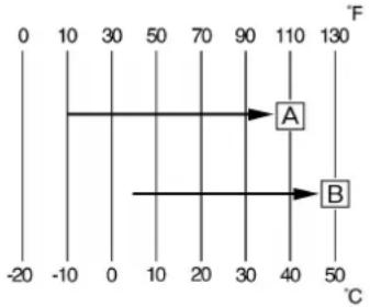  | At -10 °C (10 °F) or higherAYamalube 4 (10W-30) or SAE 10W-30 typeSE motor oilAt 5 °C (40 °F) or higherBYamalube 4 (20W-40) or SAE 20W-40 typeSE motor oil(Except for USA and CDN)API “SE” or higher grade | |
| Oil capacity:Engine oilPeriodic oil change 1.0 L (0.88 Imp qt, 1.06 US qt)Total amount 1.2 L (1.06 Imp qt, 1.27 US qt) | ||
| Air filter: Wet type element | ||
| Fuel:Type Unleaded fuel (USA)Tank capacity 6.6 L (1.45 Imp gal, 1.74 US gal)Reserve amount 1.9 L (0.42 Imp gal, 0.5 US gal) | Regular unleaded gasoline (CDN, EUROPE)Unleaded fuel only (AUS)Regular gasoline (NZ) | |
| Carburetor:Type VM20SSManufacturer MIKUNI | ||
| Spark plug:Type CR7HSA/U22FSR-UManufacturer NGK/DENSOGap 0.6 ~ 0.7 mm (0.02 ~ 0.03 in) | ||
| Clutch type: Wet, multiple-disc | ||
| Transmission:Primary reduction system GearPrimary reduction ratio 68/19 (3.579)Secondary reduction system Chain driveSecondary reduction ratio 49/13 (3.769)Transmission type Constant mesh, 5-speedOperation Left foot operationGear ratio: 1st 37/14 (2.643)2nd 3rd 4th 5th | 32/18 (1.778)25/19 (1.316)23/22 (1.045)21/24 (0.875) | |
| Chassis:Frame typeCaster angleTrail | Diamond28.7°93 mm (3.66 in) | |
| Tire:Type With tubeSize (front)Size (rear)Manufacturer (front and rear)Tire pressure (front and rear) | 70/100-17 40M90/100-14 49MCHENG SHIN100 kPa (1.00 kg/cm2, 15 psi) | |
| Brake:Front brake type Drum brakeOperation Right hand operationRear brake type Drum brakeOperation Right foot operation | ||
| Suspension:Front suspension Telescopic forkRear suspension Swingarm (link type monocross suspension) | ||
| Shock absorber:Front shock absorber Coil spring/oil damperRear shock absorber Coil spring/gas, oil damper | ||
| Wheel travel:Front wheel travel 180 mm (7.09 in)Rear wheel travel 160 mm (6.30 in) | ||
| Electrical:Ignition system CDI magneto | ||
TT-R125LW
| Model name: TT-R125LWN | (USA-except for California, CDN, AUS, NZ)TT-R125LWNC (USA for California)TT-R125LW (EUROPE) | |
| Model code number: 5HP9 (USA, AUS, NZ, EUROPE)5HPA (CDN) | ||
| Dimensions: USA, AUS, NZ,Overall length 1,885 mm (74.2 in) 1,890 mm (74.4 in)Overall width 795 mm (31.3 in)Overall height 1,085 mm (42.7 in)Seat height 805 mm (31.7 in)Wheelbase 1,270 mm (50.0 in)Minimum ground clearance 295 mm (11.6 in) | EUROPE | CDN |
| Basic weight:With oil and full fuel tank 84 kg (185 lb) | ||
| Engine:Engine type Air cooled 4-stroke, SOHCCylinder arrangement Single cylinder, forward inclinedDisplacement 124 cmBore · stroke 54.0Compression ratio 10.0:1Starting system Kickstarter | ^3 (7.57 cu.in)· 54.0 mm (2.126 · 2.126 in) | |
| Lubrication system: Wet sump | ||
Oil type or grade:Engine oil (For USA and CDN)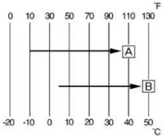 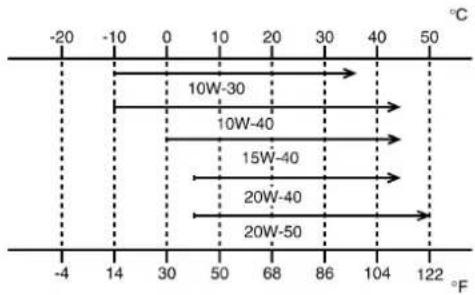 | At -10 °C (10 °F) or higherAYamalube 4 (10W-30) or SAE 10W-30 typeSE motor oilAt 5 °C (40 °F) or higherBYamalube 4 (20W-40) or SAE 20W-40 typeSE motor oil(Except for USA and CDN)API “SE” or higher grade | |
| Oil capacity:Engine oilPeriodic oil change 1.0 L (0.88 Imp qt, 1.06 US qt)Total amount 1.2 L (1.06 Imp qt, 1.27 US qt) | ||
| Air filter: Wet type element | ||
| Fuel:Type Unleaded fuel (USA)Tank capacity 6.6 L (1.45 Imp gal, 1.74 US gal)Reserve amount 1.9 L (0.42 Imp gal, 0.5 US gal) | Regular unleaded gasoline (CDN, EUROPE)Unleaded fuel only (AUS)Regular gasoline (NZ) | |
| Carburetor:Type VM20SSManufacturer MIKUNI | ||
| Spark plug:Type CR7HSA/U22FSR-UManufacturer NGK/DENSOGap 0.6 ~ 0.7 mm (0.02 ~ 0.03 in) | ||
| Clutch type: Wet, multiple-disc | ||
| Transmission:Primary reduction system GearPrimary reduction ratio 68/19 (3.579)Secondary reduction system Chain driveSecondary reduction ratio 54/13 (4.154)Transmission type Constant mesh, 5-speedOperation Left foot operationGear ratio: 1st 37/14 (2.643)2nd 3rd 4th 5th | 32/18 (1.778)25/19 (1.316)23/22 (1.045)21/24 (0.875) | |
| Chassis:Frame typeCaster angleTrail | Diamond28.5°107 mm (4.21 in) | |
| Tire:Type With tubeSize (front)Size (rear)Manufacturer (front and rear)Tire pressure (front and rear) | 70/100-19 42M90/100-16 52MINOUE RUBBER100 kPa (1.00 kg/cm2, 15 psi) | |
| Brake:Front brake type Single disc brakeOperation Right hand operationRear brake type Drum brakeOperation Right foot operation | ||
| Suspension:Front suspension Telescopic forkRear suspension Swingarm (link type monocross suspension) | ||
| Shock absorber:Front shock absorber Coil spring/oil damperRear shock absorber Coil spring/gas, oil damper | ||
| Wheel travel:Front wheel travel 180 mm (7.09 in)Rear wheel travel 168 mm (6.61 in) | ||
| Electrical:Ignition system CDI magneto | ||
EC212000
MAINTENANCE SPECIFICATIONS
EC212100
ENGINE
| Item Standard Limit | |||
Cylinder head:Warp limit ---- 0.03 mm | (0.0012 in) | ||
| Cylinder:Bore size 54.000 ~ 54.019 mmOut of round limit ---- 0.05 mm | (2.1260 ~ 2.1267 in) | ----(0.0020 in) | |
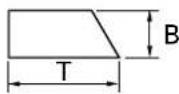
Camshaft:Drive method Chain drive (left) ----Cam dimensions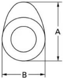 Intake “A” 25.881 ~ 25.981 mm“B” 21.195~ 21.295 mmExhaust “A” 25.841 ~ 25.941 mm“B” 21.050~ 21.150 mmCamshaft runout limit ---- 0.03 mm Intake “A” 25.881 ~ 25.981 mm“B” 21.195~ 21.295 mmExhaust “A” 25.841 ~ 25.941 mm“B” 21.050~ 21.150 mmCamshaft runout limit ---- 0.03 mm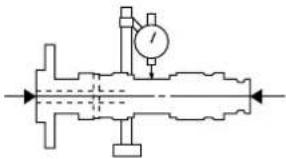 | (1.0189 ~ 1.0229 in)(0.8344 ~ 0.8384 in)(1.0174 ~ 1.0213 in)(0.8287 ~ 0.8327 in) | 25.851 mm(1.0178 in)21.165 mm(0.8333 in)25.811 mm(1.0162 in)21.020 mm(0.8276 in)(0.0012 in) | |
| Item | Standard | Limit | |
| Cam chain:Cam chain type/No. of links DID25SD DHA/88Cam chain adjustment method Automatic ---- | ---- | ||
| Rocker arm/rocker arm shaft:Shaft outside diameter 9.981 ~ 9.991 mm | (0.3930 ~ 0.3933 in) | 9.95 mm(0.3917 in) | |
| Rocker arm inside diameter 10.000 ~ 10.015 mm | (0.3937 ~ 0.3943 in) | 10.03 mm(0.3949 in) | |
| Valve, valve seat, valve guide:Valve clearance (cold) IN 0.08 ~ 0.12 mm | (0.0031 ~ 0.0047 in) | ---- | |
| EX 0.10 ~ 0.14 mm | ---- | ||
| (0.0039 ~ 0.0055 in) | |||
| Valve dimensions: | |||
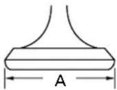 | 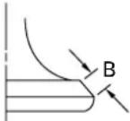 | 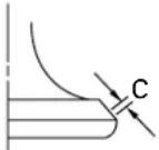 | 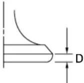 |
| Head diameter | Face width | Seat width | Margin thickness |
| “A” head diameter IN 25.9 ~ 26.1 mm | (1.0197 ~ 1.0276 in) | ---- | |
| EX 21.9 ~ 22.1 mm | ---- | ||
| “B” face width IN 1.1 ~ 3.0 mm | (0.8622 ~ 0.8701 in) | ---- | |
| EX 1.7 ~ 2.8 mm | ---- | ||
| “C” seat width IN 0.9 ~ 1.1 mm | (0.0669 ~ 0.1102 in) | 1.6 mm(0.0630 in) | |
| EX 0.9 ~ 1.1 mm | 1.6 mm(0.0630 in) | ||
| “D” margin thickness IN 0.4 ~ 0.8 mm | (0.0354 ~ 0.0433 in) | ---- | |
| EX 0.8 ~ 1.2 mm | ---- | ||
| Stem outside diameter IN 4.975 ~ 4.990 mm | (0.0315 ~ 0.0472 in) | 4.950 mm(0.1949 in) | |
| EX 4.960 ~ 4.975 mm | 4.935 mm(0.1943 in) | ||
| Guide inside diameter IN 5.000 ~ 5.012 mm | (0.1953 ~ 0.1959 in) | 5.042 mm(0.1985 in) | |
| EX 5.000 ~ 5.012 mm | 5.042 mm(0.1985 in) | ||
| Stem-to-guide clearance IN 0.010 ~ 0.037 mm | (0.1969 ~ 0.1973 in) | 0.08 mm(0.0031 in) | |
| EX 0.025 ~ 0.052 mm | 0.10 mm(0.0040 in) | ||
| Item Standard Limit | |||
Stem runout limit ---- 0.01 mm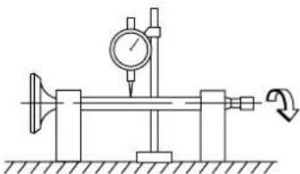 Valve seat width IN 0.9 ~ 1.1 mmEX 0.9 ~ 1.1 mm(0.0354 ~ 0.0433 in) (0.0354 ~ 0.0433 in) Valve seat width IN 0.9 ~ 1.1 mmEX 0.9 ~ 1.1 mm(0.0354 ~ 0.0433 in) (0.0354 ~ 0.0433 in) | (0.0004 in)1.6 mm(0.0630 in)1.6 mm(0.0630 in) | ||
Valve spring:Free length IN 32.55 mm (1.28 in) 31.2 mmEX 32.55 mm (1.28 in) 31.2 mmSet length (valve closed) IN 25.6 mm (1.01 in) ----EX 25.6 mm (1.01 in) ----Compressed pressure(installed) IN 137.5 ~ 158.1 NEX 137.5 ~ 158.1 N(14.0 ~ 16.1 kg, 30.86 ~ 35.49 lb)----Tilt limit * IN ---- 2.5°/1.4 mmEX ---- 2.5°/1.4 mm(2.5°/0.06 in)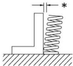 Direction of winding(top view) IN Clockwise ----EX Clockwise ---- Direction of winding(top view) IN Clockwise ----EX Clockwise ---- | (1.23 in)(1.23 in)--------(2.5°/0.06 in)(2.5°/0.06 in) | ||
| Item | Standard | Limit | |
| Piston:Piston to cylinder clearance 0.020 ~ 0.026 mm | (0.0008 ~ 0.0010 in) | 0.15 mm(0.0059 in) | |
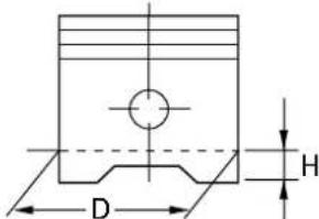
| Piston size “D” 53.977 ~ 53.996 mm | (2.1251 ~ 2.1258 in) | ---- | |
 | |||
| Piston over size (2nd) 54.5 mm (2.1457 in) ----(4th) 55.0 mm (2.1654 in) ---- | |||
| Measuring point “H” 5 mm (0.20 in) ---- | |||
| Piston off-set 0.5 mm (0.0197 in) ---- | |||
| Piston pin bore inside diameter 15.002 ~ 15.013 mm | (0.5906 ~ 0.5911 in) | 15.043 mm(0.5922 in) | |
| Piston pin outside diameter 14.991 ~ 15.000 mm | (0.5902 ~ 0.5906 in) | 14.971 mm(0.5894 in) | |
| Piston rings:Top ring | |||
 | |||
| Type Barrel ---- | |||
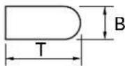
| Dimensions (B · T) 1.0 | · 2.1 mm (0.04 · 0.08 in) ---- | ||
| End gap (installed) | 0.15 ~ 0.30 mm(0.006 ~ 0.012 in) | 0.4 mm(0.016 in) | |
| Side clearance (installed) 0.035 ~ 0.090 mm | (0.0014 ~ 0.0035 in) | 0.12 mm(0.0047 in) | |
| 2nd ring | |||
 | |||
| Type Taper ---- | |||
| Dimensions (B · T) 1.0 | · 2.1 mm (0.04 · 0.08 in) ---- | ||
| End gap (installed) | 0.30 ~ 0.45 mm(0.012 ~ 0.018 in) | 0.55 mm(0.022 in) | |
| Side clearance | 0.020 ~ 0.060 mm(0.0008 ~ 0.0024 in) | 0.12 mm(0.0047 in) | |
| Oil ring | |||
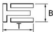 | |||
| Dimensions (B · T) 2.0 | · 2.2 mm (0.08 · 0.09 in) ---- | ||
| End gap (installed) | 0.20 ~ 0.70 mm (0.01 ~ 0.03 in) | ---- | |
| Crankshaft: | |||
| Crank width “A” 46.95 ~ 47.00 n | (1.848 ~ 1.850 in) | ---- | |
Runout limit “C” ---- 0.03 mm 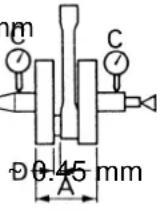 | (0.0012 in) | ||
| Big end side clearance “D” 0.15 | (0.0059 ~ 0.0177 in) | 0.5 mm(0.02 in) | |
| Clutch: | |||
| Friction plate thickness 2.92 ~ 3.08 mm | (0.115 ~ 0.121 in) | 2.8 mm(0.110 in) | |
| Quantity 5 ---- | |||
| Clutch plate thickness 1.05 ~ 1.35 mm | (0.041 ~ 0.053 in) | ---- | |
| Quantity 4 ---- | (0.008 in) | ||
| Warp limit ---- 0.2 mm | |||
| Clutch spring free length 33 mm (1.30 in) 31 mm | (1.22 in) | ||
| Quantity 4 ---- | |||
| Clutch release method Inner push, cam push ---- | |||
| Push rod bending limit ---- 0.5 mm | (0.020 in) | ||
| Shifter: | |||
| Shifter type Cam drum and guide bar ---- | |||
| Kick starter: | |||
| Type | Kick and mesh type | ---- | |
| Kick clip friction force | 6.4 ~ 13.2 N(0.65 ~ 1.35 kg, 1.4 ~ 3.0 lb) | ---- | |
| Carburetor: | |||
| I.D. mark | 5HP1 00 | ---- | |
| Main jet | (M.J) | #105 | ---- |
| Main jet nozzle | (N.J) | N-6M | ---- |
| Main air jet | (M.A.J) | ø1.2 | ---- |
| Jet needle-clip position | (J.N) | 5HGM56-2 | ---- |
| Cutaway | (C.A) | 2.5 | ---- |
| Pilot air jet 1 | (P.A.J.1) | #80 | ---- |
| Pilot air jet 2 | (P.A.J.2) | #145 | ---- |
| Pilot outlet | (P.O) | ø1.05 | ---- |
| Pilot jet | (P.J) | #15 | ---- |
| Pilot air screw (example) | (A.S) | (2-1/2 ~ 3-1/2 turns out) | ---- |
| Bypass | (B.P) | ø1.0 ---- | |
| Needle valve seat size | (V.S) | 1.8 | ---- |
| Starter jet 1 (G.S.1) #22.5 | ---- | ||
| Starter jet 2 (G.S.2) #1.2 | ---- | ||
| Fuel level | (F.L) | 6.0 ~ 7.0 mm (0.24 ~ 0.28 in) | ---- |
| Engine idle speed | 1,300 ~ 1,500 r/min | ---- | |
| Item Standard Limit | |||
| Lubrication system:Oil filter type Wire mesh type ----Oil pump type Trochoid type ----Tip clearance 0.15 mmSide clearance 0.06 ~ 0.10 mmHousing and rotor clearance 0.06 ~ 0.10 mm | (0.0059 in)(0.0024 ~ 0.0039 in)(0.0024 ~ 0.0039 in) | 0.2 mm(0.0079 in)0.15 mm(0.0059 in)0.15 mm(0.0059 in) | |
| Part to be tightened Thread size Qty | Tightening torque | ||||
| Nm m•kg ft•lb | |||||
| Spark plug M10 | · 1.0 1 | 13 1.3 9.4 | |||
| Cylinder head bolt M8 | · 1.25 4 | 22 2.2 16 | |||
| Cylinder head bolt M6 | · 1.0 2 | 10 1.0 7.2 | |||
| Oil pressure check bolt M6 | · 1.0 1 | 7 0.7 5.1 | |||
| Cylinder head side cover M6 | · 1.0 2 | 10 1.0 7.2 | |||
| Tappet cover | M45 · 1.5 2 | 18 1.8 13 | |||
| Timing chain guide | M6 · 1.0 1 | 10 1.0 7.2 | |||
| Adjusting screw (valve) and locknut | M5 · 0.5 2 | 8 0.8 5.8 | |||
| Camshaft sprocket | M8 · 1.25 1 | 20 2.0 14 | |||
| Bearing plate cover (camshaft) | M6 · 1.0 1 | 10 1.0 7.2 | |||
| Timing chain tensioner cap bolt | M6 · 1.0 1 | 8 0.8 5.8 | |||
| Timing chain tensioner | M6 · 1.0 2 | 10 1.0 7.2 | |||
| Oil pump assembly | M6 · 1.0 2 | 7 0.7 5.1 | |||
| Oil pump cover | M5 · 0.8 1 | 5 0.5 3.6 | |||
| Engine oil drain bolt | M12 · 1.5 1 | 20 2.0 14 | |||
| Carburetor joint | M6 · 1.0 2 | 10 1.0 7.2 | |||
| Carburetor joint clamp (air filter) | M4 · 0.7 1 | 2 0.2 1.4 | |||
| Coasting enricher cover | M4 · 0.7 2 | 2 0.2 1.4 | |||
| Air filter case | M6 · 1.0 3 | 7 0.7 5.1 | |||
| Muffler | M6 · 1.0 2 | 10 1.0 7.2 | |||
| Muffler | M10 · 1.25 | 1 60 | 6.0 43 | ||
| Muffler | M8 · 1.25 1 | 30 3.0 22 | |||
| Muffler guard | M6 · 1.0 7 | 10 1.0 7.2 | |||
| Spark arrester | M6 · 1.0 3 | 10 1.0 7.2 | |||
| Crankcase | M6 · 1.0 10 | 10 | 1.0 7.2 | ||
| Left crankcase cover | M6 · 1.0 7 | 10 1.0 7.2 | |||
| Drive sprocket cover | M6 · 1.0 2 | 12 1.2 8.7 | |||
| Right crankcase cover | M6 · 1.0 9 | 10 1.0 7.2 | |||
| Lead guide (CDI magneto lead) | M6 · 1.0 1 | 7 0.7 5.1 | |||
| Timing mark accessing screw | M14 · 1.5 1 | 7 0.7 5.1 | |||
| Crankshaft end accessing screw | M32 · 1.5 1 | 7 0.7 5.1 | |||
| Kickstarter crank | M12 · 1.0 1 | 50 5.0 36 | |||
| Primary drive gear | M12 · 1.0 1 | 70 7.0 50 | |||
| Clutch spring | M5 · 0.8 4 | 6 0.6 4.3 | |||
| Clutch boss | M12 · 1.0 1 | 60 6.0 43 | |||
| Adjusting screw (push rod) and locknut | M6 · 1.0 | 1 | 8 | 0.8 | 5.8 |
| Bearing plate cover (main axle) | M6 · 1.0 2 | 7 0.7 5.1 | |||
| Drive sprocket | M5 · 0.8 2 | 6 0.6 4.3 | |||
| Shift arm | M6 · 1.0 1 | 10 1.0 7.2 | |||
| Shift rod and shift pedal | M6 · 1.0 1 | 7 0.7 5.1 | |||
| Shift rod and shift arm | M6 · 1.0 1 | 7 0.7 5.1 | |||
| Shift pedal | M6 · 1.0 1 | 12 1.2 8.7 | |||
| Segment | M6 · 1.0 1 | 12 1.2 8.7 | |||
| Stopper lever | M6 · 1.0 1 | 10 1.0 7.2 | |||
NOTE:
△- marked portion shall be checked for torque tightening after break-in or before each ride.
Cylinder head tightening sequence
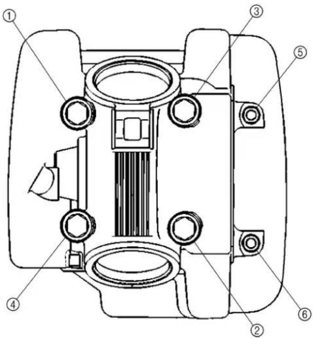
text_image
Technical diagram of a mechanical component with numbered parts for identification| Item Standard Limit | ||
| Steering system:Steering bearing type (upper) Angular bearing ----(lower) Taper roller bearing ---- | ||
| Front suspension:Front fork travel 180 mm (7.09 in) ----Fork spring free length 327 mm (12.87 in) 322 mm (12.68 in)Spring rate, STD K = 3.00 N/mm | (0.310 kg/mm, 17.4 lb/in)3(5.60 Imp oz, 5.38 US oz)----30 mm (1.18 in)Zero mm (Zero in) | ---- |
| Optional spring/spacer No ----Oil capacity 159 cm | ||
| Oil level 122 mm (4.80 in) ----Oil grade Fork oil 10W or equivalent | ||
| Inner tube outer diameter | ||
| Front fork top end | ||
| Rear suspension:Shock absorber travel | 65 mm (2.56 in) | ---- |
| Spring free length | 175 mm (6.89 in) ---- | |
| Fitting length | 165 mm (6.50 in) ---- | |
| Spring rate, STD K = 48.1 N/mm | (4.9 kg/mm, 274 lb/in)No ---- | |
| Optional spring | 1,500 kPa(15 kg/cm2, 213 psi) | ---- |
| Enclosed gas pressure | ||
| Wheel:Front wheel type | Spoke wheel | ---- |
| Rear wheel type Spoke wheel | ---- | |
| Front rim size/material | 17 · 1.40/Steel | ---- |
| Rear rim size/material | 14 · 1.60/Steel | ---- |
| Rim runout limit:Radial | ---- | 2.0 mm (0.08 in) |
| Lateral ---- | 2.0 mm (0.08 in) | |
| Drive chain:Type/manufacturer | DID428 HG(I)/DAIDO | ---- |
| Number of links | 116 links | ---- |
| Chain slack | 35 ~ 50 mm (1.4 ~ 2.0 in) | ---- |
| Chain length (10 links) | ---- | 121.4 mm(4.78 in) |
| Item | Standard | Limit |
| Drum brake:Front drum brake type Leading, trailing ----Rear drum brake type Leading, trailing ----Front drum inside diameter 110 mm (4.33 in) 111 mm (4.37 in)Rear drum inside diameter 110 mm (4.33 in) 111 mm (4.37 in)Front lining thickness 4.0 mm (0.16 in) 2.0 mm (0.08 in)Rear lining thickness 4.0 mm (0.16 in) 2.0 mm (0.08 in)Front shoe spring free length 50.5 mm (1.99 in) ----Rear shoe spring free length 50.5 mm (1.99 in) ---- | ||
| Brake lever and brake pedal:Brake lever free play (lever end) 10 ~ 15 mm (0.39 ~ 0.59 in) ----Brake pedal position (vertical height below footrest top) 1 mm (0.04 in) ----Brake pedal free play 20 ~ 30 mm (0.79 ~ 1.18 in) ----Clutch lever free play (lever end) 10 ~15 mm (0.39 ~ 0.59 in) ----Throttle grip free play 3 ~ 5 mm (0.12 ~ 0.20 in) ---- | ---- |
| Part to be tightened Thread size Q'ty | Tightening torque | ||||
| Nm m•kg ft•lb | |||||
| Upper bracket and inner tube M8 · 1.25 2 25 2.5 18Lower bracket and inner tube M10 · 1.25 2 60 6.0 43Upper bracket and steering stem M22 · 1.0 1 110 11.0 80Handlebar upper holder and upper bracket M8 · 1.25 4 23 2.3 17Steering stem and ring nut M25 · 1.0 1 Refer to NOTE. | |||||
| Front fork and cap bolt | M25 · 1.0 2 | 23 2.3 17 | |||
| Front fork and damper rod | M10 · 1.0 2 | 23 2.3 17 | |||
| Front fork and brake cable holder | M6 · 1.0 | 1 | 7 | 0.7 | 5.1 |
| Number plate | M6 · 1.0 | 1 | 7 | 0.7 | 5.1 |
| Starter knob | M11 · 1.25 | 1 | 1 | 0.1 | 0.7 |
| Starter knob stay | M6 · 1.0 | 2 | 10 | 1.0 | 7.2 |
| Grip cap upper and lower | M5 · 0.8 | 2 | 4 | 0.4 | 2.9 |
| Throttle cable cap | M4 · 0.7 | 2 | 2 | 0.2 | 1.4 |
| Brake lever mounting (bolt) | M6 · 1.0 | 1 | 7 | 0.7 | 5.1 |
| Brake lever mounting (nut) | M6 · 1.0 | 1 | 7 | 0.7 | 5.1 |
| Brake lever holder | M5 · 0.8 | 2 | 4 | 0.4 | 2.9 |
| Clutch lever mounting (bolt) | M6 · 1.0 | 1 | 7 | 0.7 | 5.1 |
| Clutch lever mounting (nut) | M6 · 1.0 | 1 | 7 | 0.7 | 5.1 |
| Clutch lever holder | M5 · 0.8 | 2 | 4 | 0.4 | 2.9 |
| Front wheel axle and axle nut | M12 · 1.25 1 | 45 4.5 32 | |||
| Front brake camshaft lever and camshaft | M6 · 1.0 | 1 | 10 | 1.0 | 7.2 |
| Rear wheel axle and axle nut | M12 · 1.25 | 1 | 60 | 6.0 | 43 |
| Rear brake camshaft lever and camshaft | M6 · 1.0 | 1 | 10 | 1.0 | 7.2 |
| Brake pedal mounting | M10 · 1.25 1 | 30 3.0 22 | |||
| Brake pedal position locknut | M6 · 1.0 | 1 | 7 | 0.7 | 5.1 |
| Front wheel nipple (spoke) | — | 36 | 2 | 0.2 | 1.4 |
| Rear wheel nipple (spoke) | — | 36 | 3 | 0.3 | 2.2 |
| Driven sprocket and wheel hub | M8 · 1.25 4 | 26 2.6 19 | |||
| Sidestand mounting (nut) | M10 · 1.25 1 | 44 4.4 32 | |||
| Engine mounting: | |||||
| Engine bracket (front) and frame | M8 · 1.25 2 | 40 4.0 29 | |||
| Engine bracket (front) and engine | M8 · 1.25 2 | 40 4.0 29 | |||
| Engine bracket (upper) and frame | M8 · 1.25 2 | 40 4.0 29 | |||
| Engine bracket (upper) and cylinder head | M8 · 1.25 | 1 | 40 | 4.0 | 29 |
| Engine and frame (rear) | M8 · 1.25 2 | 40 4.0 29 | |||
| Pivot shaft and nut | M12 · 1.25 1 | 53 5.3 38 | |||
| Relay arm and swingarm | M12 · 1.25 1 | 53 5.3 38 | |||
NOTE:
| 1. First, tighten the ring nut approximately 38 Nm (3.8 m • kg, 27 ft • lb) by using the ring nut wrench and turn the steering right and left a few times; then loosen the ring nut one turn. |
| 2. Retighten the ring nut 20 Nm (2.0 m • kg, 14 ft • lb). |
| Part to be tightened Thread size Q'ty | Tightening torque | ||||
| Nm m•kg ft•lb | |||||
| Relay arm and connecting arm M10 · 1.25 1 35 3.5 25Connecting arm and frame M10 · 1.25 1 35 3.5 25Rear shock absorber assembly and frame M12 · 1.25 1 53 5.3 38Rear shock absorber assembly and relay arm M10 · 1.25 1 35 3.5 25Rear shock absorber and locknut (preload) M46 · 1.5 1 42 4.2 30Drive chain tensioner (upper) M8 · 1.25 1 23 2.3 17 | |||||
| Drive chain tensioner (lower) | M6 · 1.0 | 1 | 7 | 0.7 | 5.1 |
| Drive chain support and swingarm | M6 · 1.0 | 2 | 7 | 0.7 | 5.1 |
| Drive chain guide and swingarm | M6 · 1.0 | 2 | 7 | 0.7 | 5.1 |
| Drive chain guard mounting | M6 · 1.0 | 2 | 7 | 0.7 | 5.1 |
| Fuel tank mounting | M6 · 1.0 | 2 | 10 | 1.0 | 7.2 |
| Fuel tank and fuel cock | M6 · 1.0 | 2 | 7 | 0.7 | 5.1 |
| Fuel tank and fuel tank bracket | M6 · 1.0 | 4 | 7 | 0.7 | 5.1 |
| Front fender mounting | M6 · 1.0 | 4 | 7 | 0.7 | 5.1 |
| Rear fender mounting | M6 · 1.0 | 4 | 7 | 0.7 | 5.1 |
| Flap guard mounting | M6 · 1.0 | 2 | 4 | 0.4 | 2.9 |
| Left side cover mounting | M6 · 1.0 | 2 | 7 | 0.7 | 5.1 |
| Seat mounting | M6 · 1.0 | 2 | 7 | 0.7 | 5.1 |
NOTE:
△- marked portion shall be checked for torque tightening after break-in or before each ride.
TT-R125LW
| Item Standard Limit | ||
| Steering system:Steering bearing type (upper) Angular bearing ----(lower) Taper roller bearing ---- | ||
| Front suspension:Front fork travel 180 mm (7.09 in) ----Fork spring free length 339 mm (13.35 in) 334 mm (13.15 in)Spring rate, STD K = 3.20 N/mm(0.330 kg/mm, 18.5 lb/in)Optional spring/spacer No ----Oil capacity 156 cm ^3 (5.49 Imp oz, 5.27 US oz)Oil level 130 mm (5.12 in) ----Oil grade Fork oil 10W or equivalent ----Inner tube outer diameter 30 mm (1.18 in) ----Front fork top end Zero mm (Zero in) ---- | ||
| Rear suspension:Shock absorber travel 65 mm (2.56 in) ----Spring free length 178 mm (7.01 in) ----Fitting length 165 mm (6.50 in) ----Spring rate, STD K = 58.9 N/mm(6.0 kg/mm, 336 lb/in) ----Optional spring No ----Enclosed gas pressure 1,500 kPa(15 kg/cm ^2 , 213 psi) ---- | ||
| Wheel:Front wheel type Spoke wheel ----Rear wheel type Spoke wheel----Front rim size/material 19 · 1.40/Steel ----Rear rim size/material 16 · 1.60/Steel ----Rim runout limit:Radial ----2.0 mm (0.08 in) 2.0 mm (0.08 in)Lateral ----2.0 mm (0.08 in) | ||
| Drive chain:Type/manufacturer DID428 HG(I)/DAIDO ----Number of links 122 links ----Chain slack 35 ~ 50 mm (1.4 ~ 2.0 in) ----Chain length (10 links) ----121.4 mm(4.78 in) | ||
| Front disc brake:Disc outside dia. · Thickness 220 · 3.0 mm (8.66 · 0.12 in) 220 · 2.5 mm(8.66 · 0.10 in)Deflection limit ----0.15 mm (0.006 in)Pad thickness 4.0 mm (0.16 in) 0.8 mm (0.03 in)Master cylinder inside dia. 11.0 mm (0.433 in) ----Caliper cylinder inside dia. 22.22 mm (0.875 in) · 2 ----Brake fluid type DOT #4 ---- | ||
| Rear drum brake:Drum brake type Leading, trailing ----Drum inside diameter 110 mm (4.33 in) 111 mm (4.37 in)Lining thickness 4.0 mm (0.16 in) 2.0 mm (0.08 in)Shoe spring free length 50.5 mm (1.99 in) ---- | ||
| Brake lever and brake pedal:Brake lever free play (lever end) 2 ~ 5 mm (0.08 ~ 0.20 in) ----Brake pedal position (vertical height below footrest top)Brake pedal free play 20 ~ 30 mm (0.79 ~ 1.18 in) ----Clutch lever free play (lever end) 10 ~ 15 mm (0.39 ~ 0.59 in) ----Throttle grip free play 3 ~ 5 mm (0.12 ~ 0.20 in) ---- |
| Part to be tightened Thread size Q'ty | Tightening torque | ||||
| Nm m·kg ft·lb | |||||
| Upper bracket and inner tube M8 · 1.25 2 25 2 .5 18Lower bracket and inner tube M10 · 1.25 2 60 6.0 43Upper bracket and steering stem M22 · 1.0 1 110 11.0 80Handlebar upper holder and upper bracket M8 · 1.25 4 23 2 .3 17Steering stem and ring nut M25 · 1.0 1 Refer to NOTE. | |||||
| Front fork and cap bolt | M25 · 1.0 2 | 23 2.3 17 | |||
| Front fork and damper rod | M10 · 1.0 2 | 23 2.3 17 | |||
| Front fork and brake hose holder | M6 · 1.0 | 2 | 7 | 0.7 | 5.1 |
| Number plate | M6 · 1.0 | 1 | 7 | 0.7 | 5.1 |
| Starter knob | M11 · 1.25 | 1 | 1 | 0.1 | 0.7 |
| Starter knob stay | M6 · 1.0 | 2 | 10 | 1.0 | 7.2 |
| Grip cap upper and lower | M5 · 0.8 | 2 | 4 | 0.4 | 2.9 |
| Throttle cable cap | M4 · 0.7 | 2 | 2 | 0.2 | 1.4 |
| Front brake master cylinder | M6 · 1.0 | 2 | 9 | 0.9 | 6.5 |
| Front brake master cylinder cap | M4 · 0.7 | 2 | 2 | 0.2 | 1.4 |
| Brake lever mounting (bolt) | M6 · 1.0 | 1 | 7 | 0.7 | 5.1 |
| Brake lever mounting (nut) | M6 · 1.0 | 1 | 7 | 0.7 | 5.1 |
| Brake lever adjuster and locknut | M6 · 0.75 | 1 | 4 | 0.4 | 2.9 |
| Clutch lever mounting (bolt) | M6 · 1.0 | 1 | 7 | 0.7 | 5.1 |
| Clutch lever mounting (nut) | M6 · 1.0 | 1 | 7 | 0.7 | 5.1 |
| Clutch lever holder | M5 · 0.8 | 2 | 4 | 0.4 | 2.9 |
| Front brake master cylinder and joint | M10 · 1.25 | 1 | 26 | 2.6 | 19 |
| Front brake hose and joint | M10 · 1.25 | 1 14 1.4 10 | |||
| Front brake hose union bolt | M10 · 1.25 | 1 26 2.6 19 | |||
| Front brake caliper and front fork M8 · 1.25 2 30 3.0 22 | |||||
| Brake caliper support bolt | M8 · 1.25 1 | 22 2.2 16 | |||
| Front brake caliper and bleed screw | M7 · 1.0 | 1 | 6 | 0.6 | 4.3 |
| Front wheel axle and axle nut | M12 · 1.25 | 1 | 45 | 4.5 | 32 |
| Front brake disc and wheel hub | M6 · 1.0 | 4 | 12 | 1.2 | 8.7 |
| Rear wheel axle and axle nut | M12 · 1.25 | 1 | 60 | 6.0 | 43 |
| Rear brake camshaft lever and camshaft | M6 · 1.0 | 1 | 10 | 1.0 | 7.2 |
| Brake pedal mounting | M10 · 1.25 | 1 30 3.0 22 | |||
| Brake pedal position locknut | M6 · 1.0 | 1 | 7 | 0.7 | 5.1 |
| Front wheel nipple (spoke) | — | 36 | 2 | 0.2 | 1.4 |
| Rear wheel nipple (spoke) | — | 36 | 3 | 0.3 | 2.2 |
NOTE:
-
First, tighten the ring nut approximately 38 Nm (3.8 m • kg, 27 ft • lb) by using the ring nut wrench and turn the steering right and left a few times; then loosen the ring nut one turn.
-
Retighten the ring nut 20 Nm (2.0 m • kg, 14 ft • lb).
| Part to be tightened Thread size Q'ty | Tightening torque | ||||
| Nm m·kg ft·lb | |||||
| Bead stopper M8 · 1.25 1 3 0.3 2.2 | |||||
| Driven sprocket and wheel hub M8 · 1.25 4 26 | 2.6 19 | ||||
| Sidestand mounting (nut) M10 · 1.25 1 44 4.4 | 32 | ||||
| Engine mounting: | |||||
| Engine bracket (front) and frame M8 · 1.25 2 | 40 4.0 29 | ||||
| Engine bracket (front) and engine M8 · 1.25 | 2 40 4.0 29 | ||||
| Engine bracket (upper) and frame M8 · 1.25 | 2 40 4.0 29 | ||||
| Engine bracket (upper) and cylinder head | M8 · 1.25 | 1 | 40 | 4.0 | 29 |
| Engine and frame (rear) | M8 · 1.25 2 | 40 4.0 29 | |||
| Pivot shaft and nut | M12 · 1.25 | 1 53 5.3 | 38 | ||
| Relay arm and swingarm | M12 · 1.25 | 1 53 5.3 | 38 | ||
| Relay arm and connecting arm | M10 · 1.25 | 1 35 3.5 | 25 | ||
| Connecting arm and frame | M10 · 1.25 | 1 35 3.5 | 25 | ||
| Rear shock absorber assembly and frame | M12 · 1.25 | 1 | 53 | 5.3 | 38 |
| Rear shock absorber assembly and relay arm | M10 · 1.25 | 1 | 35 | 3.5 | 25 |
| Rear shock absorber and locknut (preload) | M46 · 1.5 | 1 | 42 | 4.2 | 30 |
| Drive chain tensioner (upper) | M8 · 1.25 | 1 23 2.3 | 17 | ||
| Drive chain tensioner (lower) | M6 · 1.0 | 1 | 7 | 0.7 | 5.1 |
| Drive chain support and swingarm | M6 · 1.0 | 2 | 7 | 0.7 | 5.1 |
| Drive chain guide and swingarm | M6 · 1.0 | 2 | 7 | 0.7 | 5.1 |
| Drive chain guard mounting | M6 · 1.0 | 2 | 7 | 0.7 | 5.1 |
| Fuel tank mounting | M6 · 1.0 | 2 10 | 1.0 7.2 | ||
| Fuel tank and fuel cock | M6 · 1.0 | 2 | 7 | 0.7 | 5.1 |
| Fuel tank and fuel tank bracket | M6 · 1.0 | 4 | 7 | 0.7 | 5.1 |
| Front fender mounting | M6 · 1.0 | 4 | 7 | 0.7 | 5.1 |
| Rear fender mounting | M6 · 1.0 | 4 7 0 | 7 5.1 | ||
| Flap guard mounting | M6 · 1.0 | 2 4 0 | 4 2.9 | ||
| Left side cover mounting | M6 · 1.0 | 2 | 7 | 0.7 | 5.1 |
| Seat mounting | M6 · 1.0 | 2 7 0 | 7 5.1 | ||
NOTE:
△- marked portion shall be checked for torque tightening after break-in or before each ride.
FC212300
ELECTRICAL
| Item Standard Limit | ||
| CDI:Magneto-model/manufacturer 5HP-00/YAMAHA ----Charging coil resistance (color) 688 ~ 1,032 Ω at 20 °C (68 °F)(Green-Brown)Pickup coil resistance (color) 248 ~ 372 Ω at 20 °C (68 °F)(White/Red)CDI unit-model/manufacturer 5HP-00/YAMAHA ---- | ||
| Ignition coil:Model/manufacturer 4KJ-10/YAMAHA ----Minimum spark gap 6 mm (0.24 in) ----Primary coil resistance 0.18 ~ 0.28 Ω at 20 °C (68 °F) ----Secondary coil resistance 6.3 ~ 9.5 kΩ at 20 °C (68 °F) ---- |
| Part to be tightened Thread size | Q'ty | Tightening torque | |||
| Nm | m•kg | ft•lb | |||
| Pickup coil | M6 · 1.0 | 2 | 10 | 1.0 | 7.2 |
| Blind plug (neutral switch) | M10 · 1.25 | 1 | 20 | 2.0 | 14 |
| Stator | M6 · 1.0 | 3 | 10 | 1.0 | 7.2 |
| Rotor | M12 · 1.25 | 1 | 80 | 8.0 | 58 |
| Ignition coil | M6 · 1.0 | 2 | 7 | 0.7 | 5.1 |
FC220001
GENERAL TORQUE SPECIFICATIONS
This chart specifies torque for standard fasteners with standard I.S.O. pitch threads. Torque specifications for special components or assemblies are included in the applicable sections of this book. To avoid warpage, tighten multi-fastener assemblies in a crisscross fashion, in progressive stages, until full torque is reached. Unless otherwise specified, torque specifications call for clean, dry threads. Components should be at room temperature.
| A(Nut) | B(Bolt) | TORQUE SPECIFICATION | ||
| Nm m·kg ft·lb | ||||
| 10 mm | 6 mm | 6 | 0.6 | 4.3 |
| 12 mm | 8 mm | 15 | 1.5 | 11 |
| 14 mm | 10 mm | 30 | 3.0 | 22 |
| 17 mm | 12 mm | 55 | 5.5 | 40 |
| 19 mm | 14 mm | 85 | 8.5 | 61 |
| 22 mm | 16 mm | 130 | 13 | 94 |
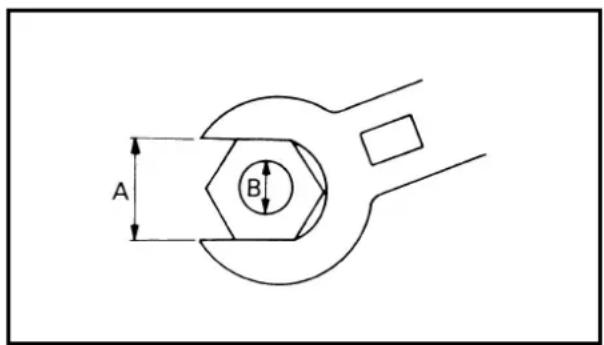
text_image
A BA: Distance between flats
B: Outside thread diameter
EC230000
DEFINITION OF UNITS
| Unit Read Definition Measure | |||
| mmcm | millimetercentimeter | 10^-3 meter 10^-2 meter | LengthLength |
| kg kilogram 10 | ^3 gram Weight | ||
| N Newton 1 kg | ·m/sec ^2 | Force | |
| Nm m·kg | Newton meterMeter kilogram | N·m m·kg | Torque Torque |
| Pa Pascal N/m | ^2 | Pressure | |
| N/mm Newton per | r millimeter N/mm Spring rate | ||
| L cm ^3 | LiterCubic centimeter | — | Volume or capacityVolume or capacity |
| r/min Revolution | per minute | — Engine speed | |
CARACTÉRISTIQUES
CARACTÉRISTIQUES GÉNÉRALES
TT-R125
text_image
Technical diagram of a mechanical component with numbered parts for identificationPARTIE CYCLE
TT-R125
text_image
Technical diagram of a mechanical component with numbered parts labeled 1 through 6RAHMEN
TT-R125
① Fuel tank breather hose
② CDI unit
③ CDI unit band
④ Clamp
⑤ CDI magneto lead
⑥ Air vent hose
⑦ Wire harness
⑧ Engine stop switch lead
⑨ Cable guide
⑩ Brake cable
(Brake hose for the TT-R125LW)
⑪ Brake cable holder
(Brake hose holder for the TT-R125LW)
A Fit the CDI unit band over the CDI unit bracket till it stops.
B Clamp the ignition coil lead.
C Clamp the wire harness coupler.
☐ Clamp the CDI magneto lead, throttle cable and starter cable.
E Clamp the CDI magneto lead so that it does not contact the push lever.
F Pass the air vent hoses between the engine and swingarm.
G Clamp the wire harness and engine stop switch lead.
H Pass the brake cable (brake hose for the TT-R125LW) into the cable guide.
☐ Clamp the brake cable.
☐ Clamp the brake hose between the paint marks.
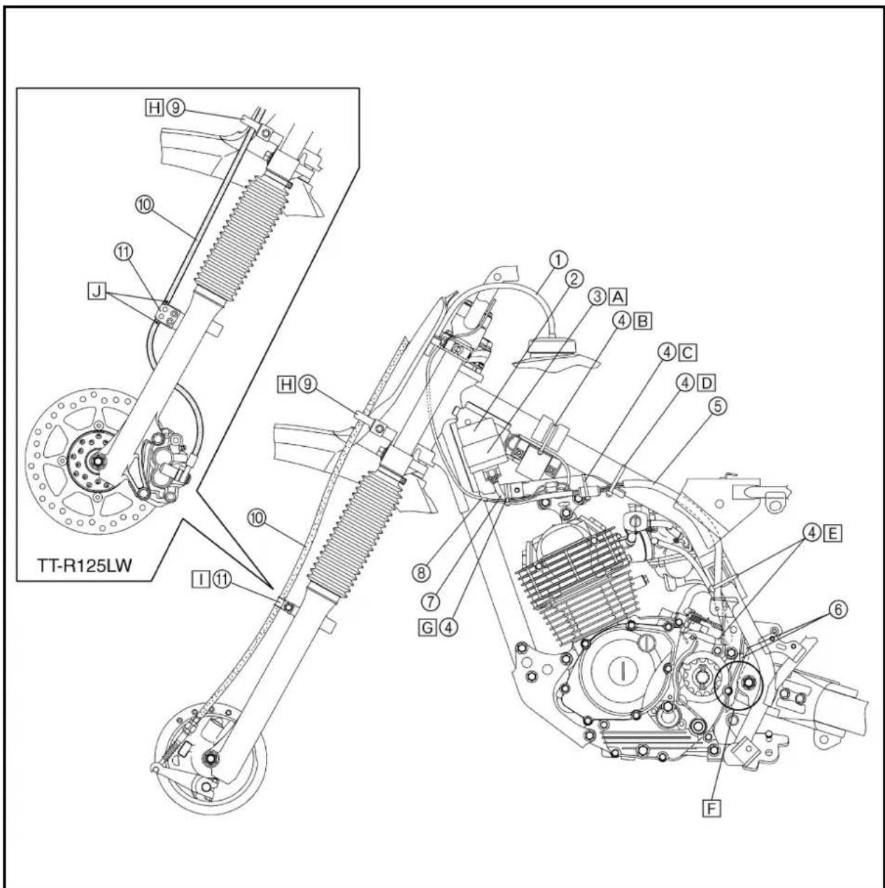
text_image
TT-R125LW H⑨ ⑩ ⑪ J H⑨ ⑪ ① ② ③A ④B ④C ④D ⑤ ⑧ ⑦ G④ ④E ⑥ FCHEMINEMENT DES CÂBLES
① Air vent hose
② Spark plug lead
③ Starter cable
④ Throttle cable
⑤ Clutch cable
⑥ Clamp
⑦ Cable guide
⑧ Engine oil breather hose
⑨ Overflow hose
A After clamping the starter cable, push it against the starter plunger.
B Put the tip of the air vent hose into the main pipe.
© Install the primary coil terminal (orange) to the ignition coil.
D Fasten the ground lead together with the ignition coil.
E Pass the clutch cable on the inside of the throttle and starter cable.
F Clamp the clutch cable with the paint in the cable guide bottom recess.
G Pass the throttle cable and starter cable into the cable guide.
H Pass the engine oil breather hose and overflow hose between the right half of the swingarm and pillar tube.
☐ Clamp the engine oil breather hose, overflow hose and air vent hose to 2 clicks.
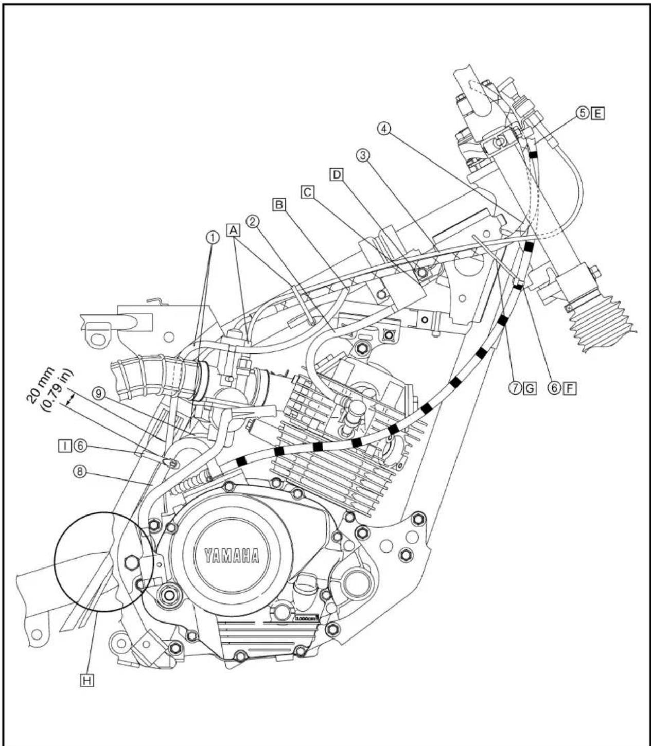
text_image
20 mm (0.79 in) YAMAHA H ① A ② B C D ③ ④ ⑤ ⑥ ⑦ ⑧ ⑨ ⑩ ⑪ ⑫ ⑥ ⑦ ⑧ ⑨ ⑩ ⑪ ⑫ ⑬ ⑭ ⑮ ⑯ ⑰ ⑱ ⑲ ⑳ ㉑ ㉒ ㉓ ㉔ ㉕ ㉖ ㉗ ㉘ ㉙ ㉚ ㉛ ㉜ ㉝ ㉟ ㉟ ㉟ ㉟ ㉟ ㉟CHEMINEMENT DES CÂBLES KABELFÜHRUNG

① Engine stop switch lead
② Engine stop switch
③ Fuel tank breather hose
④ Clamp
⑤ Brake cable
(Brake hose for the TT-R125LW)
⑥ Clutch cable
⑦ Throttle cable
A Pass the engine stop switch lead in the middle of the clutch holder.
B Clamp the engine stop switch lead to the handlebar to 3 clicks.
C Pass the brake cable (brake hose for the TT-R125LW) in front of the number plate and through the cable guide.
D Pass the clutch cable in back of the number plate.
E Insert the fuel tank breather hose into the hole in the starter knob stay more the 30 mm (1.18 in).
F Clamp the throttle cable adjuster cover to the handlebar with the clamp ends downward.
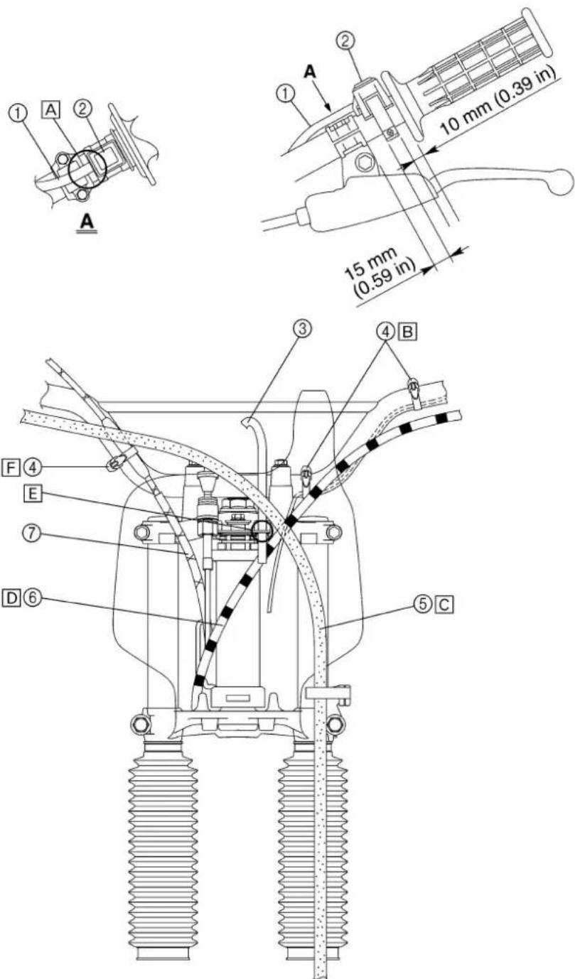
text_image
1 A 2 A 10 mm (0.39 in) 15 mm (0.59 in) 3 4 B F 4 E 7 D 6 5 C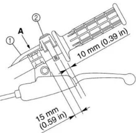
text_image
10 mm (0.39 in) 15 mm (0.59 in)CHEMINEMENT DES CÂBLES KABELFÜHRUNG

The following schedule is intended as a general guide to maintenance and lubrication. Bear in mind that such factors as weather, terrain, geographical location, and individual usage will alter the required maintenance and lubrication intervals. If you are a doubt as to what intervals to follow in maintaining and lubricating your machine, consult your Yamaha dealer.
| Dealer Note | Item Checks | and maintenance jobs | Initial Every | ||
| 10 hours(1 month) | 60 hours(6 months) | 120 hours(12 months) | |||
| * | Fuel line | Check fuel hoses for cracks or damage.Replace if necessary. | ○ | ○ | |
| Spark plug | Check condition.Clean, regap or replace if necessary. | ○ | ○ | ||
| * | Valves | Check valve clearance.Adjust if necessary. | ○ | ||
| Air filter Clean or replace element if necessary. | ○ | ○ | |||
| * | Carburetor | Check engine idling speed and starter operation.Adjust if necessary. | ○ | ○ | ○ |
| Exhaust systems | Check for leakage.Retighten if necessary.Replace gasket if necessary. | ○ | ○ | ||
| Engine oil | Check oil level and vehicle for oil leakage.Correct if necessary.Change. (Warm engine before draining.) | ○ | ○ | ○ | |
| Clutch | Check operation.Adjust or replace cable. | ○ | ○ | ○ | |
| * | Front brake | Check operation.Adjust brake lever free play.Check fluid level and leakage. (TT-R125LW only) | Every ride | ||
| * | Rear brake | Check operation.Adjust brake pedal free play and replace brake shoes if necessary. | Every ride | ||
| * | Wheels | Check balance, runout, spoke tightness and for damage.Tighten spokes and rebalance, replace if necessary. | ○ | ○ | ○ |
| * | Tires | Check tread depth and for damage.Replace if necessary.Check air pressure.Correct if necessary. | ○ | ○ | |
| * | Wheel bearings | Check bearing for looseness or damage.Replace if necessary. | ○ | ○ | |
| * | Swingarm | Check swingarm pivoting point for play.Correct if necessary.Lubricate with molybdenum disulfide grease. | ○ | ○ | ○ |
| Drive chain | Check chain slack.Adjust if necessary. Make sure that the rear wheel is properly aligned.Clean and lubricate. | Every ride | |||
| * | Steering bearings | Check bearing play and steering for roughness.Correct accordingly.Lubricate with lithium soap base grease every 120 hours. | ○ | ○ | |
| Sidestand | Check operation.Lubricate and repair if necessary. | ○ | ○ | ||

| Dealer Note | Item Checks | and maintenance jobs | Initial Every | ||
| 10 hours (1 month) | 60 hours (6 months) | 120 hours (12 months) | |||
| * | Spark arrester*1 | Clean. | ○ | ||
| * | Front fork | Check operation and for oil leakage.Correct accordingly. | ○ | ○ | |
| * | Rear shock absorber assembly | Check operation and shock absorber for oil leakage.Replace shock absorber assembly if necessary. | ○ | ○ | |
| * | Chassis fasteners | Make sure that all nuts, bolts and screws are properly tightened.Tighten if necessary. | ○ | ○ | ○ |
* : Since these items requires special tools data and technical skills, they should be serviced.
*1 : For USA
CONTRÔLES ET RÉGLAGES PÉRIODIQUES
PROGRAMME D'ENTRETIEN
Before riding for break-in operation or practice, make sure the machine is in good operating condition.
Before using this machine, check the following points.
GENERAL INSPECTION AND MAINTENANCE
| Item Routine Page | ||
| Fuel | Check that a fresh gasoline is filled in the fuel tank. Check the fuel line for leakage. | P.1-12 |
| Engine oil | Check that the oil level is correct. Check the crankcase for leakage. | P.3-7 ~ 10 |
| Gear shifter and clutch | Check that gears can be shifted correctly in order and that the clutch operates smoothly. | P.3-4 |
| Throttle grip/housing | Check that the throttle grip operation and free play are correctly adjusted. Lubricate the throttle grip and housing, if necessary. | P.3-4 ~ 5 |
| Brakes | Check the play of front and rear brake and effect of front and rear brake.Check fluid level and leakage. (TT-R125LW only) | P.3-15 ~ 20 |
| Drive chain | Check chain slack and alignment. Check that the chain is lubricated properly. | P.3-21 ~ 22 |
| Wheels | Check for excessive wear and tire pressure. Check for loose spokes and have no excessive play. | P.3-24 ~ 25 |
| Steering | Check that the handlebar can be turned smoothly and have no excessive play. | P.3-25 ~ 27 |
| Front forks and rear shock absorber assembly | Check that they operate smoothly and there is no oil leakage. P.3-23 ~ 24 | |
| Cables (wires) | Check that the clutch and throttle cables move smoothly. Check that they are not caught when the handlebars are turned or when the front forks travel up and down. | — |
| Muffler Check that the muffler is tightly mounted and has no cracks. P.4-2 | ||
| Sprocket Check that the driven sprocket tightening nut is not loose. P.3-20 | ||
| Lubrication Check for smooth operation. Lubricate if necessary. P.3-28 | ||
| Bolts and nuts Check the chassis and engine for loose bolts and nuts. — | ||
| Lead connectors | Check that the CDI magneto, CDI unit, and ignition coil are connected tightly. | P.1-5 |
CONTRÔLES ET ENTRETIENS AVANT UTILISATION
ENGINE/CLUTCH ADJUSTMENT/ THROTTLE CABLE ADJUSTMENT
INSP ADJ

text_image
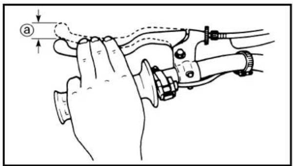
Technical diagram showing a hand operating a mechanical device with labeled component 'a' and directional arrow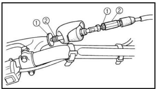
text_image
Technical diagram of a mechanical assembly with numbered components for identificationEC350000
ENGINE
CLUTCH ADJUSTMENT
1. Check:
- Clutch lever free play ⓐ Out of specification → Adjust.

Clutch lever free play ⓐ: 10 \~ 15 mm (0.39 \~ 0.59 in)
2. Adjust:
- Clutch lever free play
Clutch lever free play adjustment steps:
- Loosen the locknut ①.
- Turn the adjuster ② until free play ④ is within the specified limits.
- Tighten the locknut.
NOTE:
• Make minute adjustment on the lever side.
- After adjustment, check proper operation of clutch lever.
natural_image
Line drawing of a hand gripping a motor with a handle and gear mechanism (no text or symbols)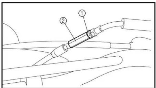
text_image
Technical diagram showing a mechanical or electrical component with labeled parts ① and ②EC35A001
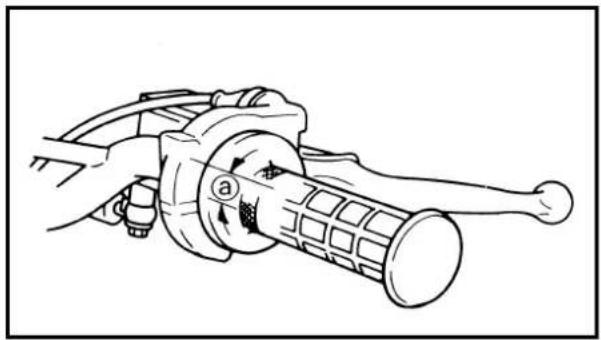
THROTTLE CABLE ADJUSTMENT
1. Check:
- Throttle grip free play ⓐ Out of specification → Adjust.

Throttle grip free play ⓐ: 3 \~ 5 mm (0.12 \~ 0.20 in)
2. Adjust:
- Throttle grip free play
Throttle grip free play adjustment steps:
- Loosen the locknut ①.
- Turn the adjuster ② until the specified free play is obtained.
- Tighten the locknut.
MOTEUR
RÉGLAGE DE L'EMBRAYAGE
1. Contrôler:
text_image
Technical diagram of a mechanical assembly with labeled component 1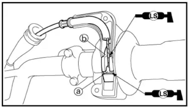
text_image
b a LS LSNOTE: ____ Before adjusting the throttle cable free play, the engine idle speed should be adjusted.
WARNING
After adjusting, turn the handlebar to right and left and make sure that the engine idling does not run faster.
THROTTLE LUBRICATION
- Remove:
- Throttle cable cap ①
- Apply:
- Lithium soap base grease On the throttle cable end ① and tube guide cable winding portion ⑥.
- Install:
- Throttle cable cap
2 Nm (0.2 m · kg, 1.4 ft · lb)
AIR FILTER CLEANING
NOTE: ____
Proper air filter maintenance is the biggest key to preventing premature engine wear and damage.
CAUTION:
Never run the engine without the air filter element in place; this would allow dirt and dust to enter the engine and cause rapid wear and possible engine damage.
N.B.:
text_image
Technical diagram of a mechanical component with labeled parts and an inset showing a cross-sectional view.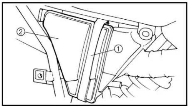
text_image
Technical diagram of a mechanical component with labeled parts ① and ②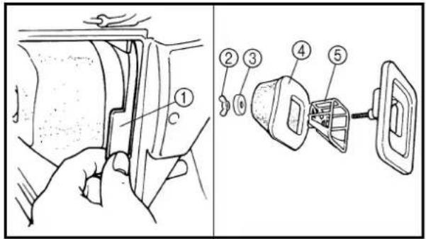
text_image
Technical diagram showing a hand inserting a component into a car compartment, with labeled parts 1 through 5.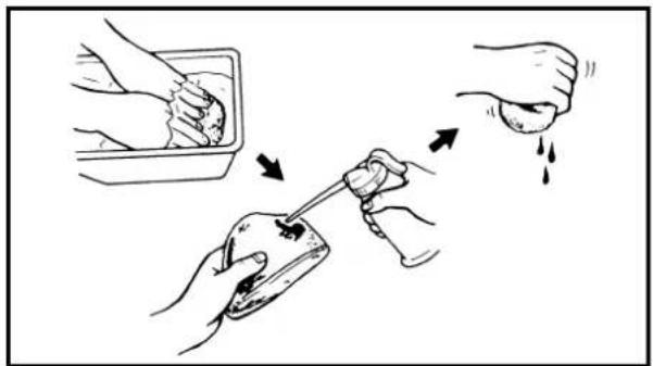
natural_image
Illustration showing three steps of a hand holding a small object, with arrows indicating motion (no text or symbols)1. Remove:
- Right side cover ①
NOTE: Loosen the quick screw ② and remove the right side cover from the holding boss @.
2. Remove:
• Band ①
• Air filter case cover ②
3. Remove:
• Air filter assembly ①
• Wing nut ②
.Washer ③
• Air filter element ④
• Air filter guide ⑤
4. Clean:
• Air filter element Clean them with solvent.
NOTE: After cleaning, remove the remaining solvent by squeezing the element.
CAUTION:
Do not twist the element when squeezing the element.
5. Inspect:
• Air filter element Damage → Replace.
1. Déposer:
- Foam-air-filter oil or engine mixing oil To the element.
NOTE:
Squeeze out the excess oil. Element should be wet but not dripping.
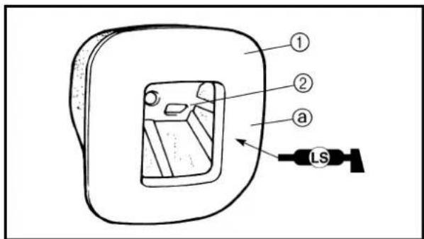
text_image
① ② a LS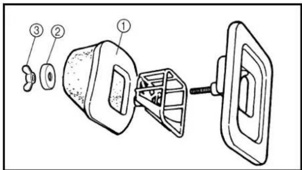
text_image
Technical diagram of a mechanical device with numbered components, likely illustrating a disassembly or assembly process.- Install:
• Air filter element ① On air filter guide ②.
- Apply:
- Lithium soap base grease On the matching surface ⓐ on air filter element.
- Install:
- Air filter element ① - Washer ② - Wing nut ③
ENGINE OIL LEVEL INSPECTION
- Start the engine, warm it up for several minutes and wait for five minutes.
- Place the machine on a level place and hold it up on upright position by placing the suitable stand under the engine.
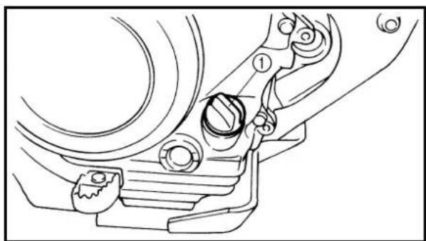
natural_image
Technical line drawing of a mechanical component with no visible text or symbols- Remove:
• Dipstick ①
CONTRÔLE DU NIVEAU D'HUILE DE MOTEUR MOTORÖLSTAND KONTROLLIEREN
INSP ADJ

6. Appliquer:
text_image
Technical diagram showing a mechanical component with labeled parts and a close-up of a tool interacting with a mechanical part.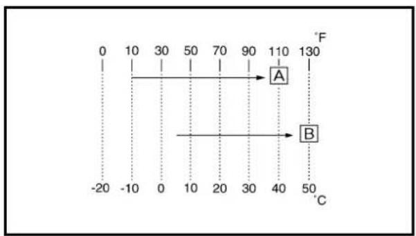
line
| X-axis | Y-axis | |---|---| | -20 | 0 | | -10 | 10 | | 0 | 30 | | 10 | 50 | | 20 | 70 | | 30 | 90 | | 40 | 110 | | 50 | 130 | The chart displays a single vertical line at X=0, where the value is 0. The segment 'A' (Y-axis) corresponds to the upper portion of the line, and the segment 'B' (Y-axis) corresponds to the lower portion of the line. The dotted lines indicate the direction of the line from left to right.4. Check:
• Oil level
Oil level should be between maximum ① and minimum ② marks.
Oil level is low → Add oil to proper level.
NOTE:
When inspecting the oil level, do not screw the dipstick into the oil tank. Insert the gauge lightly.
(For USA and CDN)

Recommended oil:
At -10^ (10°F) or higher A: Yamalube 4 (10W-30) or SAE 10W-30 type SE motor oil
At 5 °C (40 °F) or higher ☐: Yamalube 4 (20W-40) or SAE 20W-40 type SE motor oil
CAUTION:
. Do not add any chemical additives. Engine oil also lubricates the clutch and additives could cause clutch slippage.
- Do not allow foreign material to enter the crankcase.
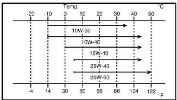
line
| Temp. | Temperature (°C) | |---|---| | -20 | 0 | | -10 | 10 | | 0 | 20 | | 10 | 30 | | 20 | 40 | | 30 | 50 | | 40 | 60 | | 50 | 70 | | 60 | 80 | | 70 | 90 | | 80 | 100 | | 90 | 110 | | 100 | 120 | | 110 | 122 | | 120 | 122 | The chart displays a single horizontal line at 10W-30°C, which is positioned between the upper and lower bounds of the horizontal axis. The x-axis represents temperature in °F, and the y-axis represents temperature in °C. There are no additional data series or labels present.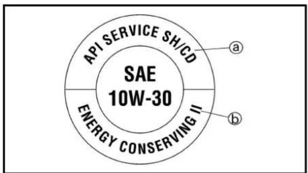
text_image
API SERVICE SHICD SAE 10W-30 ENERGY CONSERVING II a b(Except for USA and CDN)

Recommended oil:
Refer to the following chart for selection of oils which are suited to the atmospheric temperatures. Recommended engine oil classification:
API STANDARD: API "SE" or higher grade (Designed primarily for motorcycles)
CAUTION:
- Do not add any chemical additives or use oils with a grade of CD ⓐ or higher.
- Do not use oils labeled "ENERGY CONSERVING II" ⑥ or higher. Engine oil also lubricates the clutch and additives could cause clutch slippage.
- Do not allow foreign materials to enter the crankcase.
CONTRÔLE DU NIVEAU D'HUILE DE MOTEUR MOTORÖLSTAND KONTROLLIEREN
INSP ADJ

4. Contrôler:
• Niveau d'huile
-
Start the engine and let it warm up for several minutes.
-
Turn off the engine and inspect the oil level once again.
NOTE:
Wait a few minutes until the oil settles before inspecting the oil level.
ENGINE OIL REPLACEMENT
- Start the engine and warm it up for several minutes and wait for five minute.
- Place the machine on a level place and hold it on upright position by placing the suitable stand under the engine.
- Place a suitable container under the engine.
-
Remove:
-
Oil drain bolt ①
• Dipstick ②
Drain the engine oil.
- Install:
• Copper washer
• Oil drain bolt ①
New
natural_image
Mechanical assembly diagram showing a bearing and adjustment components (no text or labels)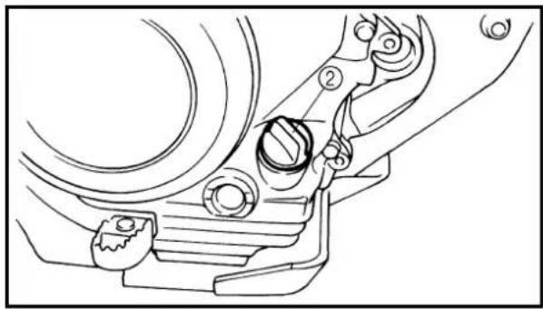
natural_image
Technical line drawing of a mechanical component with no visible text or symbols- Fill:
• Engine oil

Oil capacity:
Periodic oil change:
1.0 L (0.88 Imp qt, 1.06 US qt)
- Check:
• Oil leakage
- Check:
• Engine oil level
- Install:
• Dipstick ②
- Installer:
OIL PRESSURE INSPECTION/PILOT AIR SCREW ADJUSTMENT/ENGINE IDLING SPEED ADJUSTMENT
INSP ADJ

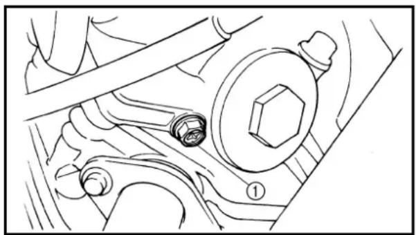
natural_image
Technical line drawing of a mechanical assembly with no visible text or symbolsOIL PRESSURE INSPECTION
- Check:
• Oil pressure
Checking steps:
- Slightly loosen the oil pressure check bolt ①.
- Start the engine and keep it idling until oil starts to seep from the oil pressure check bolt. If no oil comes out after one minute, turn the engine off so it will not seize.
- Check oil passages and oil pump for damage or leakage.
- Start the engine after solving the problem(s) and recheck the oil pressure.
• Tighten the oil pressure check bolt.

Oil pressure check bolt: 7 Nm (0.7 m · kg, 5.1 ft · lb)
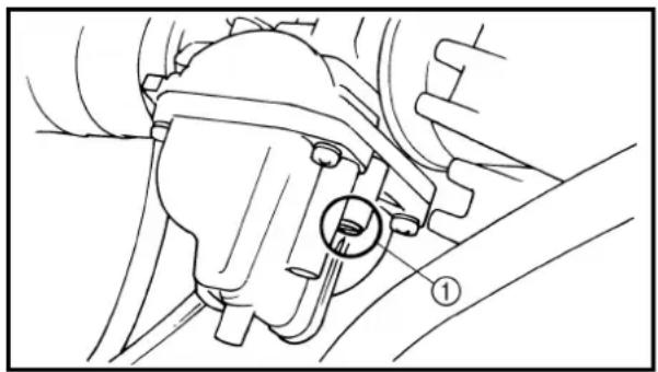
natural_image
Mechanical assembly diagram showing a component with a circular feature and numbered label (1), no readable text or symbols present.PILOT AIR SCREW ADJUSTMENT
- Adjust:
• Pilot air screw ①
Adjustment steps:
NOTE:
To optimize the fuel flow at a smaller throttle opening, each machine's pilot air screw has been individually set at the factory. Before adjusting the pilot air screw, turn it in fully and count the number of turns. Record this number as the factory-set number of turns out.
- Screw in the pilot air screw until it is lightly seated.
- Back out by the specified number of turns.

Pilot air screw: 2-1/2 \~ 3-1/2 turns out (example)
ENGINE IDLING SPEED ADJUSTMENT
- Start the engine and thoroughly warm it up.
- Attach:
- Inductive tachometer To spark plug lead.
- Adjust:
• Engine idling speed
CONTRÔLE DE LA PRESSION D'HUILE DE MOTEUR
- Contrôler:
- Pression d'huile
Étapes du contrôle:
text_image
Technical diagram of a mechanical assembly with labeled parts and directional indicators| Adjustment steps:·Adjust the pilot air screw.Refer to “PILOT AIR SCREW ADJUST-MENT” section.·Turn the throttle stop screw 1 until the specified engine idling speed. | |
| To increase idling speed →Turn the throttle stop screw 1 in a.To decrease idling speed →Turn the throttle stop screw 1 out b. | |
 | Inductive tachometer:YU-8036-B/90890-03113 |
 | Engine idling speed:1,300 ~ 1,500 r/min |
VALVE CLEARANCE INSPECTION AND ADJUSTMENT
NOTE:
• The valve clearance should be adjusted when the engine is cool to the touch.
• The piston must be at Top Dead Center (T.D.C.) on compression stroke to check or adjust the valve clearance.
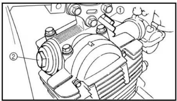
text_image
Technical diagram of a mechanical assembly with numbered components, likely for assembly or maintenance instructions.1. Remove:
• Seat
• Fuel tank
Refer to "SEAT, FUEL TANK AND SIDE COVERS" section in the CHAPTER 4.
2. Remove:
• Spark plug
• Intake tappet cover ①
• Exhaust tappet cover ②
• O-ring
3. Remove:
• Timing mark accessing screw ①
• Crankshaft end accessing screw ②
• O-ring
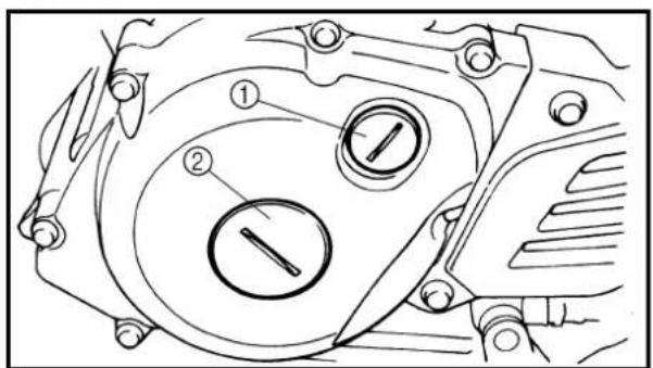
text_image
Technical diagram of a mechanical component with numbered parts and directional arrows indicating assembly or movement.Out of specification → Adjust.

Valve clearance (cold):
Intake valve:
0.08 \~ 0.12 mm
(0.0031 \~ 0.0047 in)
Exhaust valve:
0.10 \~ 0.14 mm
(0.0039 \~ 0.0055 in)
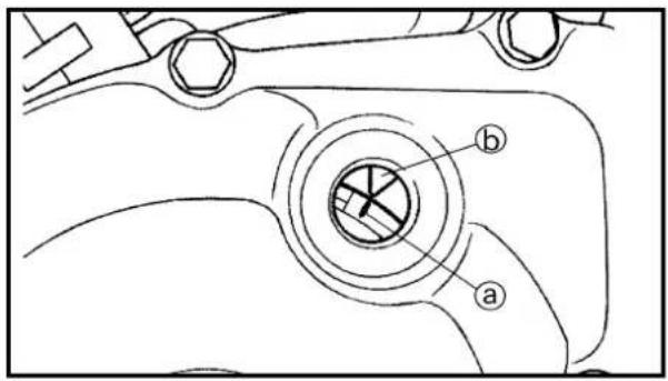
text_image
Technical diagram of a mechanical component with labeled parts a and b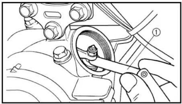
natural_image
Mechanical assembly diagram showing a hand operating a wheel with bolts and a tool (no text or symbols visible)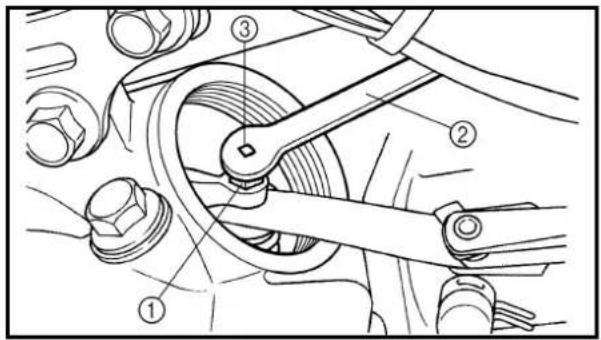
text_image
Technical diagram of a mechanical assembly with numbered components, likely illustrating a linkage or chain mechanism.Checking steps:
- Turn the crankshaft counterclockwise with a wrench.
- Align the T.D.C. mark ⓐ on the rotor with the align mark ⓑ on the crankcase cover when piston is at T.D.C. on compression stroke.
- Measure the valve clearance using a feeler gauge ①.
Out of specification → Adjust clearance.
5. Adjust:
- Valve clearance
Adjustment steps:
- Loosen the locknut ①.
- Turn the adjuster ③ in or out with the valve adjusting tool ② until specified clearance is obtained.
Turning in →
Valve clearance is decreased.
Turning out →
Valve clearance is increased.

Tappet adjusting tool:
YM-8035/90890-01311
- Hold the adjuster to prevent it from moving and tighten the locknut.

Locknut:
8 Nm (0.8 m · kg, 5.8 ft · lb)
text_image
① New LS ③ ② ① New LS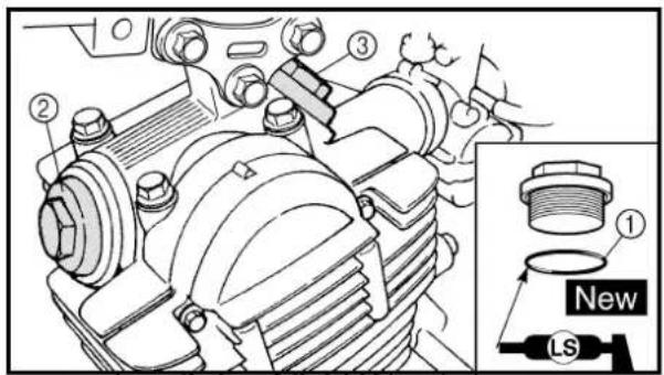
text_image
Technical diagram of a mechanical assembly with numbered components and a labeled inset showing 'New' and 'LS' parts.• Measure the valve clearance.
- If the clearance is incorrect, repeat above steps until specified clearance is obtained.
6. Install:
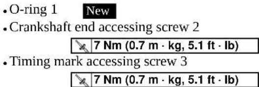
text_image
• O-ring 1 New • Crankshaft end accessing screw 2 7 Nm (0.7 m · kg, 5.1 ft · lb) • Timing mark accessing screw 3 7 Nm (0.7 m · kg, 5.1 ft · lb)NOTE: Apply the lithium soap base grease on the O-rings.
7. Install:
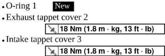
text_image
• O-ring 1 New • Exhaust tappet cover 2 18 Nm (1.8 m · kg, 13 ft · lb) • Intake tappet cover 3 18 Nm (1.8 m · kg, 13 ft · lb)NOTE: Apply the lithium soap base grease on the O-rings.
8. Install:
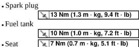
text_image
• Spark plug 13 Nm (1.3 m · kg, 9.4 ft · lb) • Fuel tank 10 Nm (1.0 m · kg, 7.2 ft · lb) • Seat 7 Nm (0.7 m · kg, 5.1 ft · lb)Refer to "SEAT, FUEL TANK AND SIDE COVERS" section in the CHAPTER 4.
- Be sure the exhaust pipe and muffler are cool before cleaning the spark arrester.
- Do not start the engine when cleaning the exhaust system.
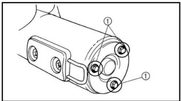
text_image
Technical diagram of a mechanical component with numbered parts labeled ①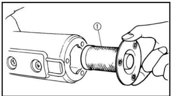
natural_image
Technical line drawing of a mechanical assembly with a hand holding a flanged component (no text or symbols present)1. Remove:
• Bolt (spark arrester) ①
2. Remove:
- Spark arrester ① Pull the spark arrester out of the muffler.
3. Clean:
- Spark arrester Tap the spark arrester lightly, then use a wire brush to remove any carbon deposits.
4. Install:
- Spark arrester Insert the spark arrester into the muffler and align the bolt holes.
• Bolt (spark arrester)
10 Nm (1.0 m · kg, 7.2 ft · lb)
NETTOYAGE DU PARE-ÉTINCELLES
(pour les USA)
AVERTISSEMENT
Bleed the brake system if:
. The system has been disassembled.
• A brake hose has been loosened or removed.
• The brake fluid is very low.
. The brake operation is faulty.
A dangerous loss of braking performance may occur if the brake system is not properly bleed.
- Remove:
- Brake master cylinder cap
• Diaphragm - Bleed:
- Brake fluid
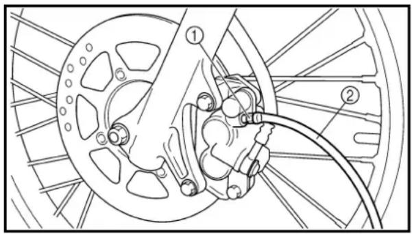
natural_image
Technical line drawing of a bicycle wheel assembly with labeled components (no text or symbols present)Air bleeding steps:
a. Add proper brake fluid to the reservoir.
b. Install the diaphragm. Be careful not to spill any fluid or allow the reservoir to overflow.
c. Connect the clear plastic tube ② tightly to the caliper bleed screw ①.
d. Place the other end of the tube into a container.
e. Slowly apply the brake lever several times.
f. Pull in the lever. Hold the lever in position.
g. Loosen the bleed screw and allow the lever to travel towards its limit.
h. Tighten the bleed screw when the lever limit has been reached; then release the lever.

Bleed screw:
6 Nm (0.6 m · kg, 4.3 ft · lb)
i. Repeat steps (e) to (h) until of the air bubbles have been removed from the system.
PARTIE CYCLE
PURGE DE L'AIR DU SYSTÈME DE FREINAGE (TT-R125LW)
AVERTISSEMENT
If bleeding is difficult, it may be necessary to let the brake fluid system stabilize for a few hours. Repeat the bleeding procedure when the tiny bubbles in the system have disappeared.
j. Add brake fluid to the level line on the reservoir.
WARNING
Check the operation of the brake after bleeding the brake system.
- Install:
• Diaphragm
• Brake master cylinder cap
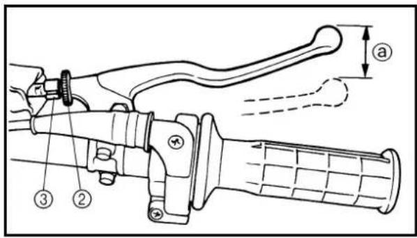
text_image
Technical diagram of a mechanical lever assembly with numbered parts and dimension annotation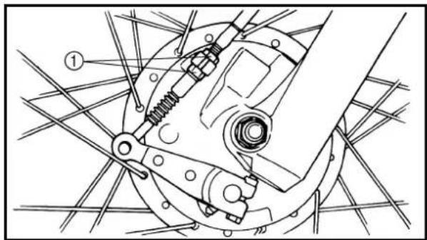
natural_image
Mechanical assembly diagram showing a linkage mechanism with no visible text or symbolsFRONT BRAKE ADJUSTMENT TT-R125
- Check:
- Brake lever free play ⓐ
Out of specification → Adjust.
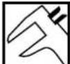
Brake lever free play ⓐ: 10 \~ 15 mm (0.39 \~ 0.59 in)
- Adjust:
- Brake lever free play
Brake lever free play adjustment steps:
- Loosen the locknuts ①.
- Turn the locknuts until free play ⓐ is within the specified limits by changing their tightening position.
• Tighten the locknuts.
NOTE:
For minute adjustment, loosen the locknut ② on the lever side and adjust with the adjuster ③.
CAUTION:
Make sure that there is no brake drag after adjusting the brake lever free play.
N.B.:
text_image
Technical diagram of a manual tool with labeled parts and dimension annotationTT-R125LW
- Check:
- Brake lever free play ⓐ
Out of specification → Adjust.

Brake lever free play ⓐ: 2 \~ 5 mm (0.08 \~ 0.20 in)
- Adjust:
- Brake lever free play
Brake lever free play adjustment steps:
- Loosen the locknut ①.
- Turn the adjuster ② until the free play ④ is within the specified limits.
• Tighten the locknut.
CAUTION:
Make sure that there is no brake drag after adjusting the brake lever free play.
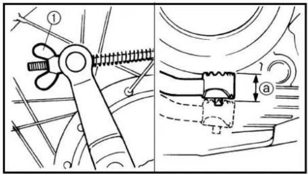
text_image
Technical diagram showing mechanical assembly with labeled parts and a magnified detail view of a component with dimension 'a'.Out of specification → Adjust.

Brake pedal free play ⓐ: 20 \~ 30 mm (0.79 \~ 1.18 in)
- Adjust:
- Brake pedal free play
Brake pedal free play adjustment step:
Turn the adjuster ① until the free play ④ is within the specified limits.
CAUTION:
Make sure that there is no brake drag after adjusting the brake pedal play.
TT-R125LW
- Contrôler:
text_image
Technical diagram of a mechanical assembly with numbered components and dimension annotationsBRAKE PEDAL HEIGHT ADJUSTMENT
- Check:
- Brake pedal height ⓐ
Out of specification → Adjust.

Brake pedal height ⓐ: 1 mm (0.04 in)
- Adjust:
- Brake pedal height
Pedal height adjustment steps:
- Loosen the locknut ①.
- Turn the adjusting bolt ② until the pedal height ④ is within specified height.
• Tighten the locknut.
FRONT BRAKE PAD INSPECTION AND REPLACEMENT (TT-R125LW)
- Remove:
Plug
- Inspect:
- Brake pad thickness ⓐ
Out of specification → Replace as a set.
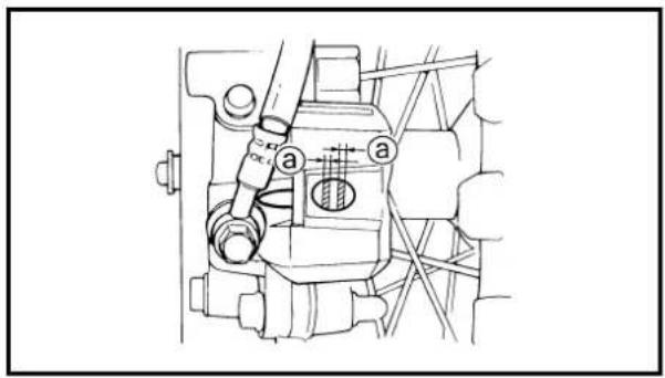
text_image
Technical diagram of a mechanical assembly with labeled parts 'a' and directional arrows indicating motion or flow.| Brake pad thickness ⓐ: | ||
| Standard | ||
| 4.0 mm(0.16 in) | 0.8 mm(0.03 in) | |
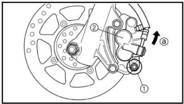
text_image
Technical diagram of a brake system with labeled components and directional arrow- Replace:
- Brake pad
Brake pad replacement steps:
- Remove the brake caliper support bolt ①.
- Turn the brake caliper ② counterclockwise ④.
- Replace the brake pads ③.
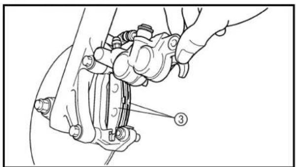
natural_image
Technical line drawing of a mechanical assembly with no visible text or symbolsRÉGLAGE DE LA HAUTEUR DE LA PÉDALE DE FREIN
- Contrôler:
natural_image
Technical line drawing of a bicycle brake system with labeled components (no text or symbols present)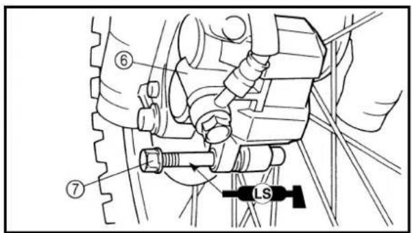
text_image
Technical diagram showing mechanical assembly with numbered components and labeled 'LS' component- Connect the transparent hose ④ to the bleed screw ⑤ and place the suitable container under its end.
- Loosen the bleed screw and push the brake caliper piston in.
CAUTION:
Do not reuse the drained brake fluid.
• Tighten the bleed screw.

Bleed screw: 6 Nm (0.6 m · kg, 4.3 ft · lb)
• Install the brake caliper ⑥ and brake caliper support bolt ⑦.
NOTE:
Apply the lithium soap base grease on the caliper support bolt.

Brake caliper support bolt: 22 Nm (2.2 m · kg, 16 ft · lb)
- Inspect:
- Brake fluid level
Refer to "BRAKE FLUID LEVEL INSPECTION" section in the CHAPTER 3.
- Check:
- Brake lever operation
A softly or spongy feeling → Bleed brake system.
Refer to "BRAKE SYSTEM AIR BLEEDING" section.
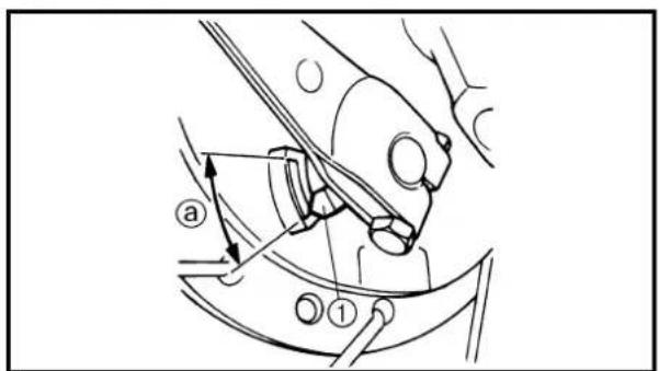
text_image
Technical diagram showing mechanical assembly with labeled parts and directional arrows• Brake shoe lining wear limit
Brake shoe lining wear limit checking steps:
- Fully pull in the brake lever and hold it in position.
- Then check the brake shoe wear indicator ① is within the wear limit ⓐ.
Outside the limit → Replace the brake shoe.
Refer to "FRONT WHEEL AND FRONT BRAKE" section in the CHAPTER 5.
text_image
Technical diagram showing mechanical assembly with labeled parts and directional arrows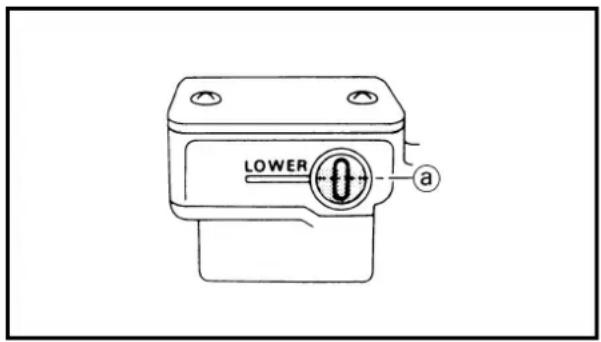
text_image
LOWER a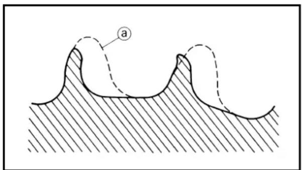
text_image
a- Brake shoe lining wear limit
Brake shoe lining wear limit checking steps:
- Fully push down the brake pedal and hold it in position.
- Then check the brake shoe wear indicator ① is within the wear limit ⓐ.
Outside the limit → Replace the brake shoe.
Refer to "REAR WHEEL AND REAR BRAKE" section in the CHAPTER 5.
- Place the brake master cylinder so that its top is in a horizontal position.
- Inspect:
- Brake fluid level
Fluid at lower level → Fill up.
① Lower level

Recommended brake fluid: DOT #4
WARNING
- Use only designated quality brake fluid to avoid poor brake performance.
- Refill with same type and brand of brake fluid; mixing fluids could result in poor brake performance.
- Be sure that water or other contaminants do not enter brake master cylinder when refilling.
- Clean up spilled fluid immediately to avoid erosion of painted surfaces or plastic parts.
SPROCKETS INSPECTION
- Inspect:
• Sprocket teeth ⓐ
Excessive wear → Replace.
NOTE: ____
Replace the drive, driven sprockets and drive chain as a set.
CONTRÔLE DES MÂCHOIRES DE FREIN
1. Examiner:
text_image
Diagram showing a chain with labeled parts, including numbered annotations ① and ②.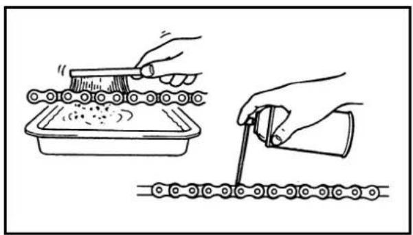
natural_image
Illustration showing hands using a tool to clean or store material over a chain, with no visible text or symbols.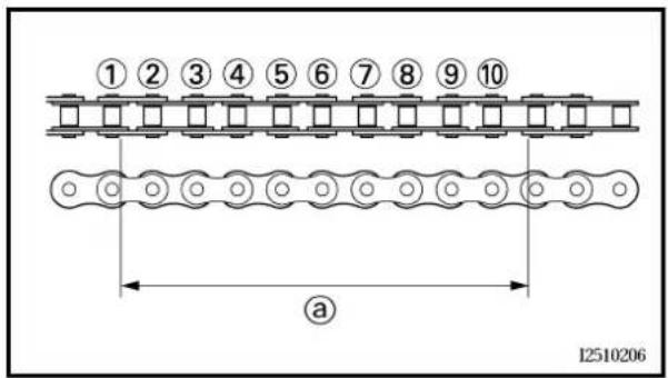
text_image
①②③④⑤⑥⑦⑧⑨⑩ a 12510206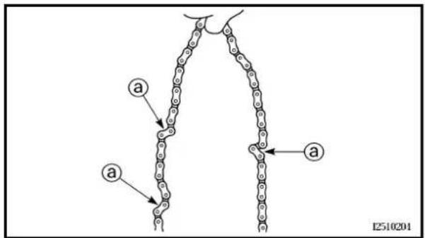
text_image
a a a 12510201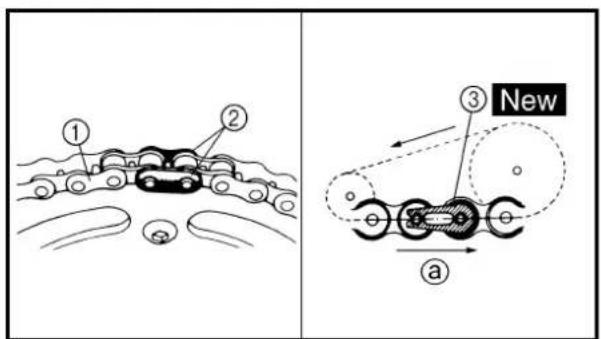
text_image
Diagram illustrating vehicle motion with labeled components and a new mechanical component, showing two scenarios (① and ②) with motion arrows.EC369002
DRIVE CHAIN INSPECTION
1. Remove:
• Master link clip
• Joint ①
- Drive chain ②
2. Clean:
- Drive chain
Place it in kerosene, and brush off as much dirt as possible. Then remove the chain from the kerosene and dry the chain.
3. Measure:
- Drive chain length (10 links) @
Out of specification → Replace.

Drive chain length (10 links):
4. Check:
• Drive chain stiffness ⓐ
Clean and oil the chain and hold as illustrated.
Stiff → Replace drive chain.
5. Install:
- Drive chain ①
• Joint ② - Master link clip ③
New
CAUTION:
Be sure to install the master link clip to the direction as shown.
① Turning direction
CONTRÔLE DE LA CHAÎNE DE TRANSMISSION
1. Déposer:
natural_image
Illustration of a hand using a tool to adjust a chain gear mechanism (no text or symbols present)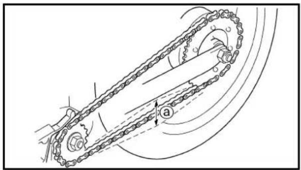
natural_image
Mechanical diagram showing a chain with rotating components and motion arrows (no text or symbols)- Lubricate:
- Drive chain

Drive chain lubricant: SAE 10W-30 motor oil or suitable chain lubricants
DRIVE CHAIN SLACK ADJUSTMENT
-
Elevate the rear wheel by placing the suitable stand under the engine.
-
Check:
- Drive chain slack ⓐ In the center between the drive axle and rear wheel axle. Out of specification → Adjust.

Drive chain slack: 35 \~ 50 mm (1.4 \~ 2.0 in)
NOTE:
Before checking and/or adjusting, rotate the rear wheel through several revolutions and check the slack several times to find the tightest point. Check and/or adjust chain slack with rear wheel in this "tight chain" position.
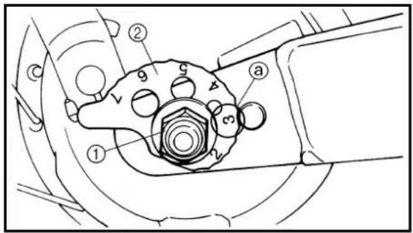
text_image
Technical diagram of a mechanical assembly with numbered components and labeled parts- Adjust:
- Drive chain slack
Drive chain slack adjustment steps:
- Loosen the axle nut ①.
- Turn both drive chain pullers ② the same amount @ and adjust them to the stopper in the same position so that the drive chain slack is within the specified limits.
CAUTION:
Too small chain slack will overload the engine and other vital parts; keep the slack within the specified limits.
- Tighten the axle nut while pushing down the drive chain.

Axle nut: 60 Nm (6.0 m · kg, 43 ft · lb)
- Lubrifier:
natural_image
Mechanical diagram showing a gear and wheel assembly with an arrow indicating motion direction (no text or symbols)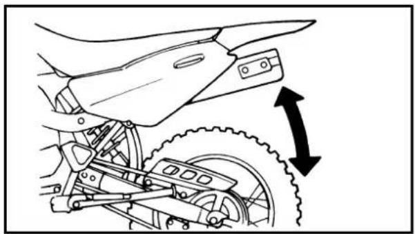
natural_image
Technical line drawing of a motorcycle's front wheel and side-mounted gear assembly (no text or symbols)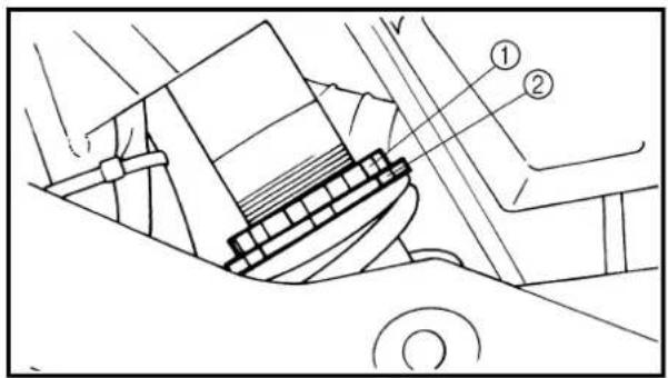
text_image
Technical diagram showing a mechanical component with numbered parts labeled ① and ②EC36C000
FRONT FORK INSPECTION
1. Inspect:
- Front fork smooth action Operate the front brake and stroke the front fork. Unsmooth action/oil leakage → Repair or replace.
REAR SHOCK ABSORBER ASSEMBLY INSPECTION
1. Inspect:
- Swingarm smooth action Abnormal noise/unsmooth action → Grease the pivoting points or repair the pivoting points. Damage/oil leakage → Replace.
REAR SHOCK ABSORBER SPRING PRELOAD ADJUSTMENT
- Elevate the rear wheel by placing the suitable stand under the engine.
- Remove:
- Left side cover
- Loosen:
- Locknut ①
- Adjust:
- Spring preload By turning the adjuster ②.
Stiffer → Increase the spring preload. (Turn the adjuster ② in.)
Softer → Decrease the spring preload. (Turn the adjuster ② out.)
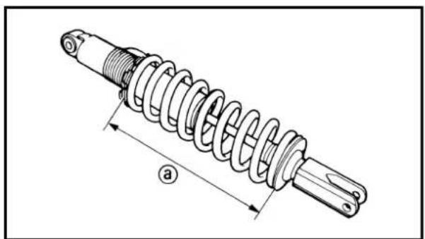
natural_image
Technical line drawing of a mechanical spring assembly with dimension label (a), no text or symbols present| Spring length (installed) a: | ||
| Standard length Extent of adjustment | ||
| 165 mm(6.50 in) | 155 ~ 175 mm(6.10 ~ 6.89 in) | |
INSPECTION DE LA FOURCHE AVANT
1. Examiner:
- Be sure to remove all dirt and mud from around the locknut and adjuster before adjustment.
- The length of the spring (installed) changes 1.5 mm (0.06 in) per turn of the adjuster.
CAUTION:
Never attempt to turn the adjuster beyond the maximum or minimum setting.
- Tighten:
- Locknut
42 Nm (4.2 m · kg, 30 ft · lb)
- Install:
- Left side cover
7 Nm (0.7 m · kg, 5.1 ft · lb)
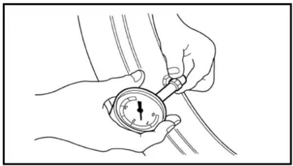
natural_image
Line drawing of hands holding a dial indicator gauge (no text or symbols present)EC36Q000
TIRE PRESSURE CHECK
- Measure:
• Tire pressure
Out of specification → Adjust.

Standard tire pressure: 100 kPa (1.00 kg/cm², 15 psi)
NOTE:
- Check the tire while it is cold.
- Loose bead stoppers allow the tire to slip off its position on the rim when the tire pressure is low.
- A tilted tire valve stem indicates that the tire slips off its position on the rim.
- If the tire valve stem is found tilted, the tire is considered to be slipping off its position. Correct the tire position.
CONTRÔLE DE LA PRESSION DE GONFLAGE DE PNEU REIFENDRUCK PRÜFEN
INSP ADJ

N.B.:
Bend/damage → Replace.
Loose spoke → Retighten.
- Tighten:
• Spokes
| Front 2 Nm (0.2 m · kg, 1.4 ft · lb) | |
| Rear 3 Nm (0.3 m · kg, 2.2 ft · lb) |
NOTE:
Be sure to retighten these spokes before and after break-in. After a practice check spokes for looseness.
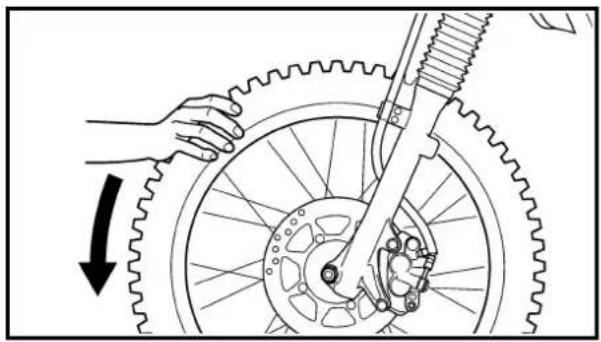
natural_image
Diagram of a bicycle wheel assembly with gear and chain, showing hand positioning and motion direction (no text or symbols)EC36T000
WHEEL INSPECTION
- Inspect:
- Wheel runout
Elevate the wheel and turn it.
Abnormal runout → Replace.
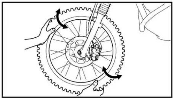
natural_image
Diagram of hands operating a bicycle gear mechanism with rotating wheels and a wheel (no text or symbols)- Inspect:
• Bearing free play
Exist play → Replace.
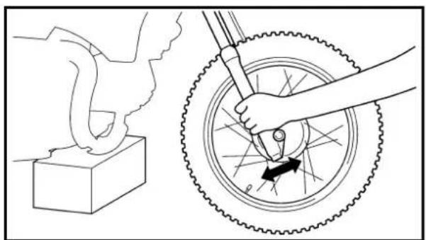
natural_image
Diagram showing a hand using a tool to lift a bicycle wheel, with no text or symbols present.STEERING HEAD INSPECTION AND ADJUSTMENT
-
Elevate the front wheel by placing a suitable stand under the engine.
-
Check:
• Steering shaft
Grasp the bottom of the forks and gently rock the fork assembly back and forth.
Free play → Adjust steering head.
INSPECTION ET SERRAGE DES RAYONS
- Examiner:
• Rayons ①
Déformation/endommagement → Remplacer.
natural_image
Technical line drawing of a mechanical assembly with rotating arms and housing (no text or symbols)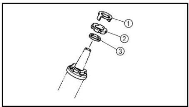
text_image
Technical diagram showing a mechanical assembly with three labeled parts, likely for assembly or maintenance instructions.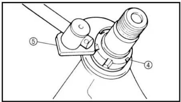
text_image
Technical diagram of a mechanical assembly with numbered components labeled ④ and ⑤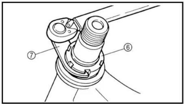
text_image
Technical diagram of a mechanical assembly with numbered parts labeled ⑦ and ⑥3. Check:
- Steering smooth action Turn the handlebar lock to lock. Unsmooth action → Adjust steering ring nut.
4. Adjust:
• Steering ring nut
Steering ring nut adjustment steps:
- Remove the number plate and starter knob.
- Remove the handlebar and upper bracket.
- Remove the special washer ①
- Remove the upper ring nut ②, and rubber washer ③.
- Loosen the lower ring nut ④ using the steering nut wrench ⑤.

Steering nut wrench: YU-33975/90890-01403
- Tighten the lower ring nut ⑥ using steering nut wrench ⑦ and turn the steering right and left a few times.
NOTE:
Set the torque wrench to the steering nut wrench so that they form a right angle.

Steering nut wrench: YU-33975/90890-01403

Lower ring nut (initial tightening): 38 Nm (3.8 m · kg, 27 ft · lb)
- Loosen the lower ring nut one turn.
- Retighten the lower ring nut using the steering nut wrench.
WARNING
Avoid over-tightening.
Hakenschlüssel: YU-33975/90890-01403
Hakenschlüssel: YU-33975/90890-01403

text_image
Technical diagram showing mechanical assembly steps with numbered components and directional arrows indicating movement or force.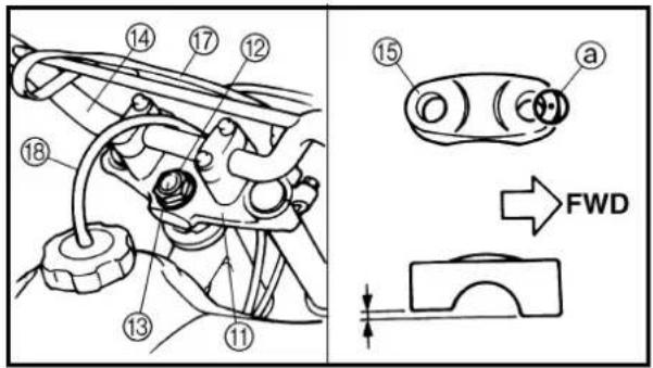
text_image
Technical diagram showing mechanical assembly with numbered components and FWD indicator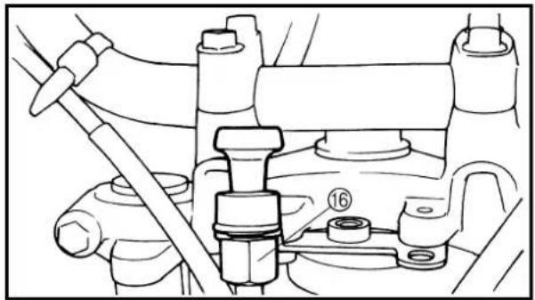
natural_image
Technical line drawing of a mechanical assembly with no visible text or symbols
Ring nut (final tightening): 20 Nm (2.0 m · kg, 14 ft · lb)
- Check the steering stem by turning it lock to lock. If there is any binding, remove the steering stem assembly and inspect the steering bearings.
• Install the rubber washer ⑧, upper ring nut ⑨ and special washer ⑩.
NOTE:
- Tighten the upper ring nut until it contacts the rubber washer.
- Insert the special washer pawls into the slots. If the slots are not aligned, tighten the upper ring nut for alignment.
• Install the upper bracket ⑪, steering stem nut ⑫, cap ⑬, handlebar ⑭, upper handlebar holder ⑮, starter knob nut ⑯ and number plate ⑰.
NOTE:
- The upper handlebar holder should be installed with the punched mark ⓐ forward.
- Insert the end of fuel breather hose ⑱ into the hole of the starter knob stay.
CAUTION:
First tighten the bolts on the front side of the handlebar holder, and then tighten the bolts on the rear side.

Pinch bolt (upper bracket):
25 Nm (2.5 m · kg, 18 ft · lb)
Steering stem nut:
110 Nm (11.0 m · kg, 80 ft · lb)
Handlebar upper holder:
23 Nm (2.3 m · kg, 17 ft · lb)
Starter knob nut:
1 Nm (0.1 m · kg, 0.7 ft · lb)
Number plate:
7 Nm (0.7 m · kg, 5.1 ft · lb)

Écrou annulaire (serrage final): 20 Nm (2,0 m • kg, 14 ft • lb)
To ensure smooth operation of all components, lubricate your machine during setup, after break-in, and after every ride.
① All control cable
② Brake and clutch lever pivots
③ Shift pedal pivot
④ Footrest pivot
⑤ Throttle-to-handlebar contact
⑥ Drive chain
⑦ Tube guide cable winding portion
⑧ Throttle cable end
⑨ Brake and clutch cable ends
(Clutch cable end only for the TT-R125LW)
A Use Yamaha cable lube or equivalent on these areas.
B Use SAE 10W-30 motor oil or suitable chain lubricants.
C Lubricate the following areas with high quality, lightweight lithium-soap base grease.
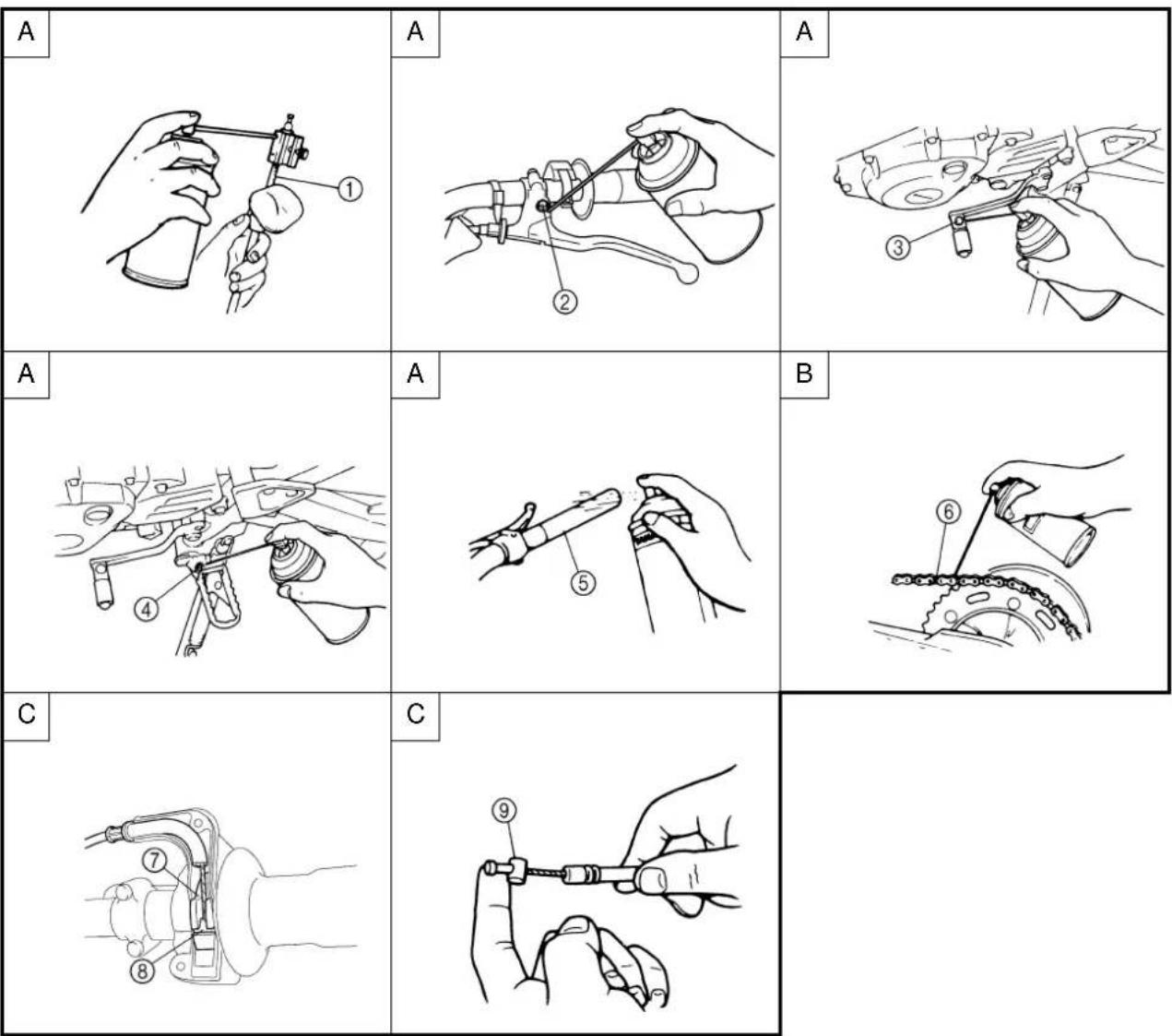
text_image
A A A A A A B C C ⑦ ⑧ ⑨ ⑥LUBRIFICATION
text_image
Technical diagram of a mechanical component with labeled parts ① and ②, showing directional arrow and structural details.EC370000
ELECTRICAL
EC371001
SPARK PLUG INSPECTION
- Remove:
- Spark plug
- Inspect:
- Electrode ①
Wear/damage → Replace.
• Insulator color ②
Normal condition is a medium to light tan color.
Distinctly different color → Check the engine condition.
NOTE:
When the engine runs for many hours at low speeds, the spark plug insulator will become sooty, even if the engine and carburetor are in good operating condition.
- Measure:
• Plug gap ⓐ
Use a wire gauge or thickness gauge.
Out of specification → Regap.

Spark plug gap:
0.6 \~ 0.7 mm (0.02 \~ 0.03 in)
Standard spark plug:
CR7HSA (NGK)
U22FSR-U (DENSO)
- Clean the plug with a spark plug cleaner if necessary.
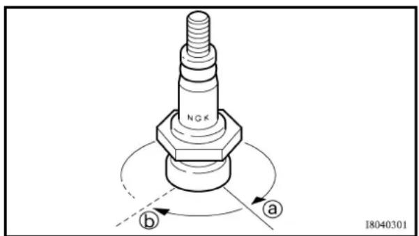
text_image
NGK a b I8040301- Tighten:
- Spark plug
13 Nm (1.3 m · kg, 9.4 ft · lb)
NOTE:
- Before installing a spark plug, clean the gasket surface and plug surface.
- Finger-tighten ⓐ the spark plug before torquing to specification ⓑ.
PARTIE ÉLECTRIQUE INSPECTION DE LA BOUGIE
- Déposer:
• Bougie
- Examiner:
- Électrodes ① Usure/endommagement → Remplacer.
③ Side covers removal
④ Number plate removal
| Extent of removal Order Part name Q'ty Remarks | |||
| Preparation for removal | SEAT, FUEL TANK AND SIDE COVERS REMOVALTurn the fuel cock to “OFF”. | ||
| 1↑ 2↓ 3↓ 4↑ | 1 Seat 12 Air scoop (left and right) 23 Fuel hose 1 Remove on fuel tank side.4 Fitting band 15 Bolt (fuel tank) 26 Fuel tank 17 Left side cover 18 Right side cover 19 Number plate | 1 | |
MOTEUR
SELLE, RÉSERVOIR DE CARBURANT ET CACHES LATÉRAUX

Extent of removal:
① Muffler removal
| Extent of removal Order Part name Q'ty Remarks | ||||
| Preparation for removal | Right side | MUFFLER REMOVALcover Refer to “SEAT, FUEL TANK AND SIDECOVERS” section. | ||
| 1 | 1 Bolt (spark arrester) 32 Spark arrester 13 Nut (muffler) 24 Bolt (muffler) 15 Muffler | 1 | ||
POT D'ÉCHAPPEMENT

text_image
Technical diagram of a mechanical assembly with numbered parts for identificationExtent of removal:
① Carburetor removal
| Extent of removal Order Part name Q'ty Remarks | ||||
| Preparation for removal | Fuel tank | CARBURETOR REMOVALRefer to “SEAT, FUEL TANK AND SIDE | COVERS” section. | |
| 1 | 1 Fuel hose 12 Over flow hose 13 Air vent hose 24 Starter plunger 15 Carburetor top cover 16 Clamp (air cleaner joint) 1 Loosen the screw (air cleaner joint).7 Clamp (carburetor joint) 1 Loosen the screws (carburetor joint).8 Carburetor | |||
CARBURATEUR

text_image
2Nm (0.2m·kg,1.4ft·lb) NewExtent of removal:
① Carburetor disassembly
| Extent of removal Order Part name Q'ty Remarks | |||
| CARBURETOR DISASSEMBLYThrottle cable 1Throttle valve 1 Refer to “REMOVAL POINTS”. | |||
| Jet needle set 1Carburetor top cover 1Starter plunger 1Float chamber 1Float pivot pin 1Float 1Needle valve 1Main jet washer 1Needle valve seat holder 1Needle valve seat 1Main jet Main jet nozzle Pilot jet Pilot air jet 1Pilot air jet 2Pilot air screw 1 Refer to “REMOVAL POINTS”. | |||
| Throttle stop screw Coasting enricher | 11 | ||
DÉMONTAGE DU CARBURATEUR
natural_image
Technical line drawing of a mechanical assembly with no visible text or symbols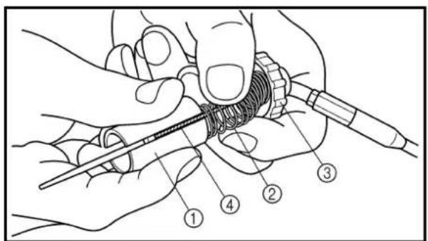
text_image
Technical diagram showing a hand holding a tool with numbered parts labeled 1 to 4HANDLING NOTE
At high altitudes, the atmospheric pressure is lower. This can make the fuel mixture too rich, leading to such problems as fouled.
Spark plugs and slow response at high engine speeds. A special part, High Altitude Main Jet ① #102.5 (620-1423A-71-A0) is available to correct this.
EC463000
REMOVAL POINTS
Throttle valve
- Remove:
• Throttle valve ①
• Spring (throttle valve) ②
• Carburetor top cover ③
- Throttle cable ④
NOTE:
While compressing the spring (throttle valve), disconnect the throttle cable.
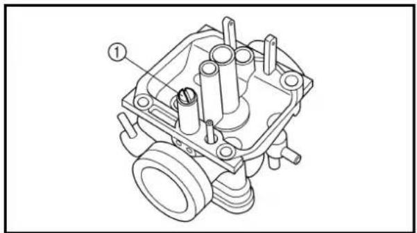
natural_image
Technical line drawing of a mechanical component with no visible text or symbolsPilot air screw
- Remove:
. Pilot air screw ①
NOTE:
To optimize the fuel flow at a smaller throttle opening, each machine's pilot air screw has been individually set at the factory. Before removing the pilot air screw, turn it in fully and count the number of turns. Record this number as the factory-set number of turns out.
REMARQUE
natural_image
Line drawing of a hand holding an air gun with a device, no text or symbols presentEC464000
INSPECTION
Carburetor
- Inspect:
• Carburetor body
Contamination → Clean.
NOTE:
- Use a petroleum based solvent for cleaning. Blow out all passages and jets with compressed air.
- Never use a wire.
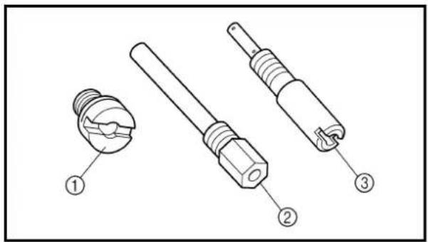
text_image
Technical diagram showing three types of electrical connectors with numbered labels- Inspect:
• Main jet ①
• Main jet nozzle ②
• Pilot jet ③
NOTE:
- Use a petroleum based solvent for cleaning. Blow out all passages and jets with compressed air.
- Never use a wire.
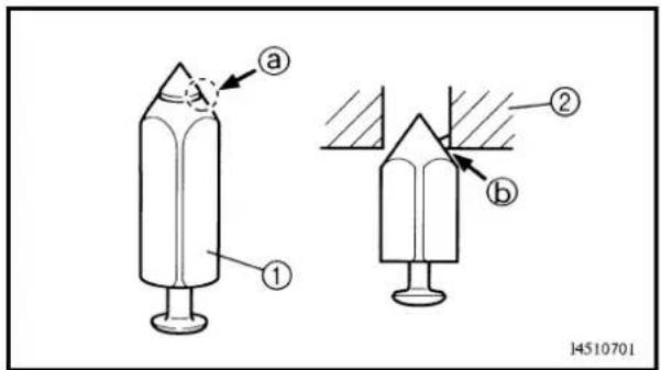
text_image
a ① ② b 14510701Needle valve
- Inspect:
- Needle valve ①
- Needle valve seat ②
Grooved wear ⓐ → Replace.
Dust ⓑ → Clean.
NOTE:
Always replace the needle valve and needle valve seat as a set.
INSPECTION
Carburateur
- Examiner:
text_image
Technical diagram showing a hand adjusting a mechanical component with labeled parts ①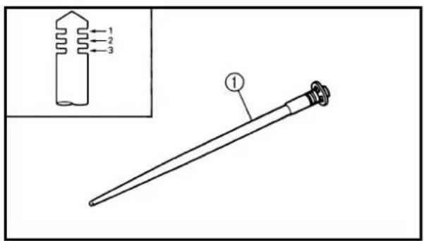
text_image
Diagram of a laboratory pipette with labeled parts and an inset showing a component with three numbered parts.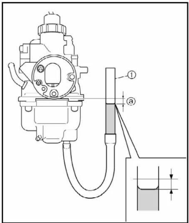
text_image
Technical diagram of a mechanical device with labeled parts and a magnified inset showing measurement scale.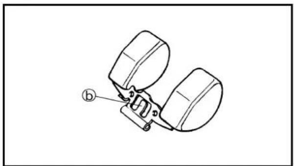
natural_image
Technical line drawing of a mechanical clamp or bracket assembly (no text or symbols)EC464301
Throttle valve
- Check:
• Free movement
Stick → Repair or replace.
NOTE:
Insert the throttle valve ① into the carburetor body, and check for free movement.
EC464401
Jet needle
- Inspect:
• Jet needle ①
Bends/wear → Replace.
- Clip groove
Free play exists/wear → Replace.
- Clip position
Standard clip position: No. 2 Groove
Fuel level
- Measure:
• Fuel level ⓐ
Out of specification → Adjust.

Fuel level:
6.0 \~ 7.0 mm (0.24 \~ 0.28 in)
Below the float chamber mat- ing surface
| Measurement and adjustment steps:• Connect the fuel level gauge 1 to the float chamber. | |
 | Fuel level gauge:YM-1312-A/90890-01312 |
- Hold the fuel level gauge vertically next to the float chamber mating surface.
- Loosen the drain screw.
- Measure the fuel level with the fuel level gauge.
NOTE:
Keep the carburetor and fuel level gauge vertically when measuring the fuel level.
• If the fuel level is not within specification, inspect the needle valve seat and needle valve.
• If either is worn, replace them both.
- If both are fine, adjust the fuel level by bending the float tab ⑥ on the float.
• Recheck the fuel level.
Boisseau
- Contrôler:
natural_image
Technical line drawing of a mechanical assembly with two bearing parts and a numbered component (no text or symbols)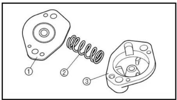
text_image
Technical diagram of a mechanical assembly with numbered components for identification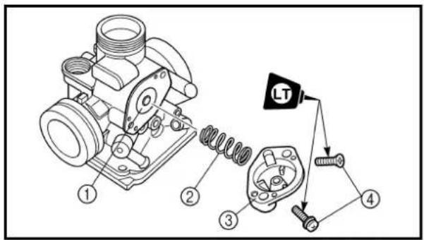
text_image
Technical diagram of a mechanical assembly with numbered components and a labeled component 'LT'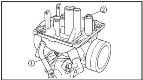
text_image
Technical diagram of a mechanical assembly with numbered components labeled ① and ②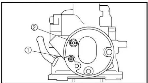
text_image
Technical diagram of a mechanical component with numbered parts labeled ① and ②EC464600
Float
- Inspect:
- Float ① Damage → Replace.
Coasting enricher
- Inspect:
- Diaphragm ① - Spring ② - Cover ③ Tears (diaphragm)/damage → Replace.
ASSEMBLY AND INSTALLATION
Carburetor
- Install:
• Diaphragm ① • Spring ② • Cover ③ • Screw ④

2 Nm (0.2 m · kg, 1.4 ft · lb)
- Install:
- Throttle stop screw ① - Pilot air screw ②
Note the following installation points:
- Turn in the pilot air screw until it is lightly seated. - Turn out the pilot air screw by the number of turns recorded before removing.

Pilot air screw:
2-1/2 \~ 3-1/2
(example)
- Install:
- Pilot air jet 1 ① - Pilot air jet 2 ②
Flotteur
- Examiner:
- Flotteur ①
text_image
Technical diagram of a mechanical assembly with numbered components for identification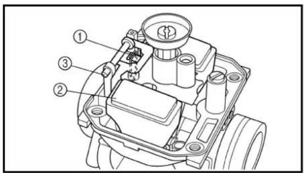
text_image
Technical diagram of a mechanical assembly with numbered components labeled ①, ②, and ③.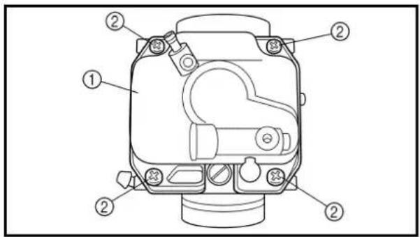
text_image
Technical diagram of a mechanical device with numbered components for identification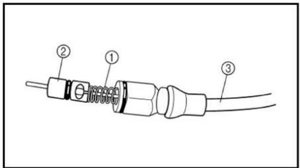
text_image
Diagram of a cable connector with labeled parts 1, 2, and 3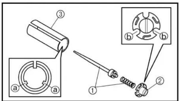
text_image
Technical diagram showing mechanical assembly steps with labeled components and numbered parts4. Install:
• Pilot jet ①
- Main jet nozzle ②
• Main jet ③
- Needle valve seat ④
- Needle valve seat holder ⑤
- Main jet washer ⑥
5. Install:
- Needle valve ①
• Float ②
• Float pivot pin ③
NOTE:
• After installing the needle valve to the float, install them to the carburetor.
- Check the float for smooth movement.
6. Install:
• Gasket
- Float chamber ①
• Screw (float chamber) ②
7. Install:
• Spring ①
• Starter plunger ②
On starter cable ③.
8. Install:
• Jet needle set ①
- Needle holder ②
On throttle valve ③.
NOTE:
Align the projections ⓐ on the throttle valve with the grooves ⓑ in the needle holder.
4. Installer:
text_image
Exploded view diagram of a mechanical assembly with numbered parts for identification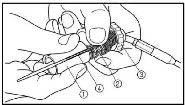
text_image
Technical diagram showing hands using a tool to adjust a mechanical component with numbered parts labeled 1 to 4.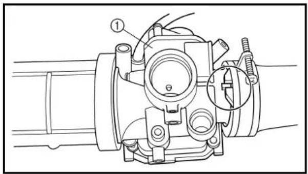
natural_image
Technical line drawing of a mechanical component with no visible text or symbols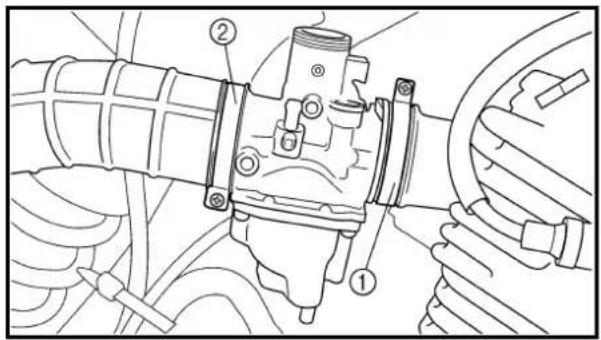
text_image
Technical diagram of a mechanical assembly with numbered components, likely illustrating a valve or coupling mechanism.9. Install:
• Carburetor top cover ①
• Spring (throttle valve) ②
• Throttle valve ③
On throttle cable ④.
NOTE:
While compressing the spring, connect the throttle cable.
Carburetor installation
1. Install:
• Carburetor assembly ①
NOTE:
Install the projection between the carburetor joint slots.
2. Tighten:
• Screw (carburetor joint) ①
• Screw (air cleaner joint) ②
text_image
Technical diagram of a vehicle engine assembly with numbered components for identification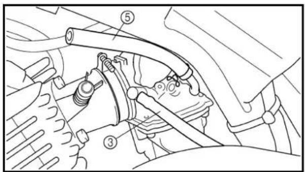
text_image
Technical diagram of a vehicle engine showing labeled parts including hoses, springs, and exhaust system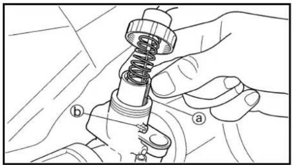
natural_image
Technical illustration of a mechanical assembly with hands holding a spring-loaded component (no text or symbols)3. Install:
• Carburetor top cover ①
- Starter plunger ②
- Air vent hose ③
• Over flow hose ④
- Fuel hose ⑤
NOTE:
Align the slit ⓐ of the throttle valve with the tab ⓑ of the carburetor body.
4. Adjust:
- Idle speed Refer to "ENGINE IDLING SPEED ADJUSTMENT" section in the CHAPTER 3.
3. Installer:
Extent of removal:
① Cylinder head side cover and tappet cover removal
| Extent of removal Order Part name Q'ty Remarks | ||||
| Preparation for removal | Seat and fuel tank Refer to “SEAT, FUEL TANK AND Muffler Refer to “MUFFLER” section.Carburetor Refer to “CARBURETOR” section.CDI unit Remove from the frame. | D SIDE COVERS” section. | ||
| 1 Engine bracket 12 Spark plug 13 Cylinder head side cover 14 Tappet cover 25 Crankshaft end accessing screw 16 Timing mark accessing screw | ||||
CULASSE
CACHE LATÉRAL DE CULASSE ET COUVRE-POUSSOIRS

Extent of removal:
① Cylinder head removal
| Extent of removal Order Part name Q'ty Remarks | ||||
| head | CYLINDER HEAD REMOVAL1 Bolt (camshaft sprocket) 12 Bolt (timing chain tensioner cap) 13 Timing chain tensioner 14 Gasket5 Camshaft sprocket 16 Cylinder head 17 Dowel pin 28 Gasket | 1 | Refer to “REMOVAL POINTS”.1 | |
CULASSE
text_image
Technical diagram of a mechanical component with labeled parts a and b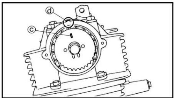
text_image
Technical diagram of a mechanical assembly with labeled components (a, b, c) and circular featuresREMOVAL POINTS
Cylinder head
1. Align:
- "I" mark
(with stationary pointer)
Checking steps:
- Turn the crankshaft counterclockwise with a wrench.
- Align the "I" mark ⓐ on the rotor with the stationary pointer ⓑ on the crankcase cover. When the "I" mark is aligned with the stationary pointer, the piston is at the Top Dead Center (T.D.C.).
NOTE:
In order to be sure that the piston is at Top Dead Center, the match mark © on the camshaft sprocket must align with the stationary pointer ⓐ on the cylinder head as shown in the illustration.
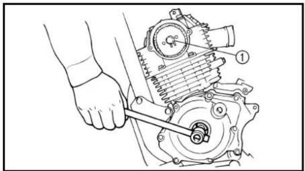
natural_image
Technical line drawing of a mechanical assembly with a hand operating a wrench (no text or symbols present)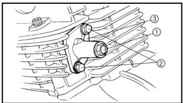
text_image
Technical diagram of a mechanical assembly with numbered components labeled ①, ②, and ③.2. Loosen:
• Camshaft sprocket bolt ①
NOTE:
Remove the bolt while holding the rotor nut with a wrench.
3. Remove:
- Bolt (timing chain tensioner cap) ①
- Bolt (timing chain tensioner) ②
- Timing chain tensioner ③
PIÈCES À DÉPOSER
Culasse
1. Aligner:
text_image
Technical diagram of a mechanical assembly with labeled parts ①, ②, and a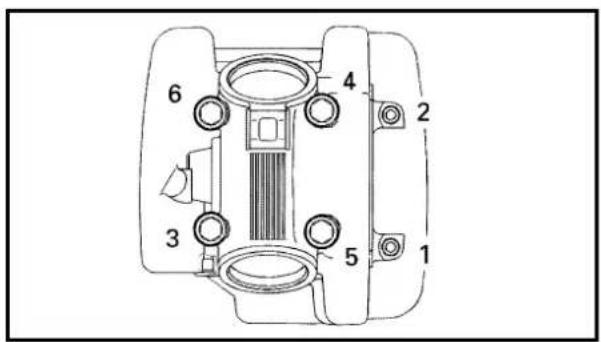
text_image
Technical diagram of a mechanical device with numbered components for identification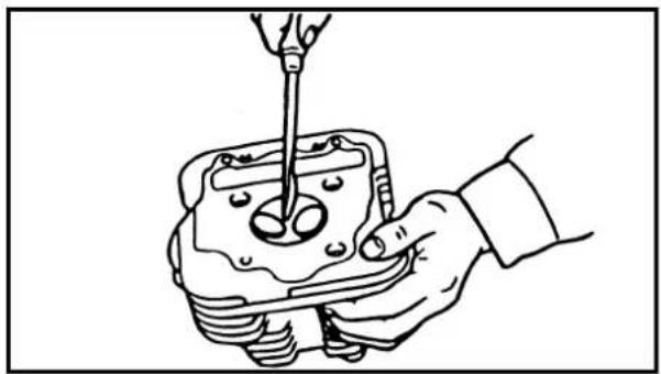
natural_image
Line drawing of a hand using a screwdriver to adjust or install a mechanical component (no text or symbols present)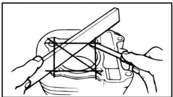
natural_image
Technical line drawing of hands using a tool to adjust or install a mechanical component (no text or symbols present)4. Remove:
• Bolt (camshaft sprocket) ①
- Camshaft sprocket ②
NOTE:
Attach a wire ⓐ to the timing chain to prevent it from falling into the crankcase.
5. Remove:
• Bolts (cylinder head)
- Cylinder head
NOTE: \_\_\_\_
- Loosen the bolts 1/4 turn each and remove then after all are loosened.
- Loosen the bolts starting with the lowest number one.
INSPECTION
Cylinder head
1. Eliminate:
• Carbon deposits (from the combustion chambers)
Use a rounded scraper.
NOTE:
Do not use a sharp instrument to avoid damaging or scratching:
- Spark plug threads
- Valve seats
2. Inspect:
- Cylinder head
Scratches/damage → Replace.
3. Inspect:
- Cylinder head warpage
Out of specification → Re-surface.
Warpage measurement and re-surfacing steps:
- Attach a straightedge and a thickness gauge on the cylinder head.
• Measure the warpage.
4. Déposer:
natural_image
Technical line drawing of a mechanical component with concentric rings and mounting holes (no text or symbols)
Warpage limit: 0.03 mm (0.0012 in)
- If the warpage is out of specification, resurface the cylinder head. - Place #400 \~ 600 grit wet sandpaper on the surface plate, and re-surface the head using a figure-eight sanding pattern.
NOTE:
Rotate the cylinder head several times to avoid removing too much material from one side.
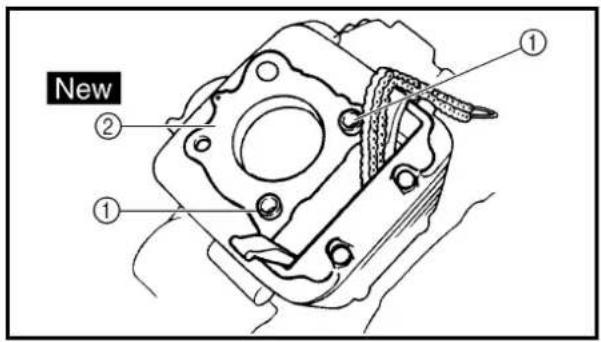
text_image
New ① ② ①ASSEMBLY AND INSTALLATION Cylinder head
- Install:
. Dowel pin ①
• Gasket ②
New
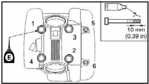
text_image
1 E 2 3 4 5 6 10 mm (0.39 in)- Install:
• Cylinder head
• Copper washer
• Bolt (cylinder head)
| M8 2 | 2 Nm (2.2 m · kg, 16 ft · lb) | |
| M6 10 | Nm (1.0 m · kg, 7.2 ft · lb) |
NOTE:
- Apply Quick gasket ^® (YAMAHA Bond No.1215) on end of the cylinder head bolts (M6), as shown.
- Apply the engine oil on the contact surfaces of the bolts (cylinder head) and copper washers.
- Follow the numerical order shown in the illustration. Tighten the bolts in two stages.
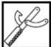
Quick gasket®: ACC-QUICK-GS-KT YAMAHA Bond No.1215: 90890-85505

text_image
Technical diagram of a mechanical component with labeled parts a and b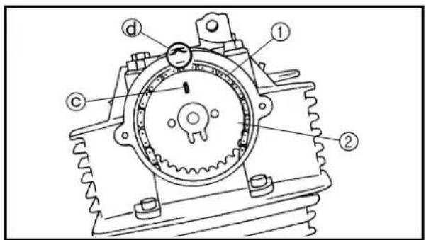
text_image
Technical diagram of a mechanical gear assembly with labeled components3. Install:
• Timing chain
• Camshaft sprocket
Installation steps:
- Turn the crankshaft counterclockwise with a wrench.
- Align the "I" mark ⓐ on the rotor with the stationary pointer ⓑ on the crankcase cover.
- Align the match mark © on the camshaft sprocket with the stationary pointer ⓐ on the cylinder head.
- Fit the timing chain ① onto camshaft sprocket ② and install the camshaft sprocket on the camshaft.
NOTE:
When installing the camshaft sprocket, keep the timing chain as tense as possible on the exhaust side.
CAUTION:
Do not turn the crankshaft during installation of the camshaft. Damage or improper valve timing will result.
- Remove the safety wire from the timing chain.
4. Install:
.Washer
• Bolt (camshaft sprocket)
NOTE:
Temporarily tighten the bolt (camshaft sprocket) at this point.
3. Installer:
natural_image
Illustration of hands using a tool to adjust a mechanical component (no text or symbols present)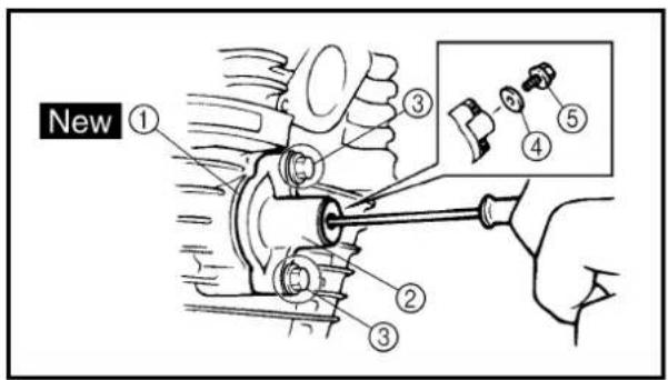
text_image
New ① ③ ④ ⑤5. Install:
• Timing chain tensioner
Installation steps:
- While pressing the tensioner rod lightly with fingers, use a thin screwdriver and wind the tensioner rod up fully clockwise. - With the rod fully wound, install the gasket ① and the chain tensioner ②, and tighten the bolts ③ to the specified torque.

Bolt (chain tensioner): 10 Nm (1.0 m · kg, 7.2 ft · lb)
- Release the screwdriver, check the tensioner rod to come out and tighten the gasket ④ and the cap bolt ⑤ to the specified torque.

Cap bolt (timing chain tensioner): 8 Nm (0.8 m · kg, 5.8 ft · lb)
6. Turn:
• Crankshaft Counterclockwise several turns
7. Check:
- Rotor "I" mark Align with the crankcase stationary pointer. - Camshaft match mark Align with the cylinder head stationary pointer. Out of alignment → Adjust.
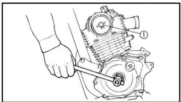
natural_image
Mechanical assembly diagram showing a hand using a wrench to adjust a gear mechanism (no text or symbols present)8. Tighten:
• Bolt ① 20 Nm (2.0 m · kg, 14 ft · lb)
NOTE:
Tighten the bolt while holding the rotor nut with a wrench.
5. Installer:
- Valve clearance Out of specification → Adjust. Refer to “VALVE CLEARANCE INSPECTION AND ADJUSTMENT” section in the CHAPTER 3.
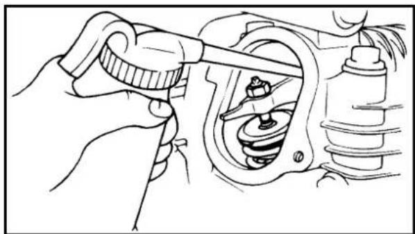
natural_image
Line drawing of a hand using a tool to adjust or install a mechanical component (no text or symbols visible)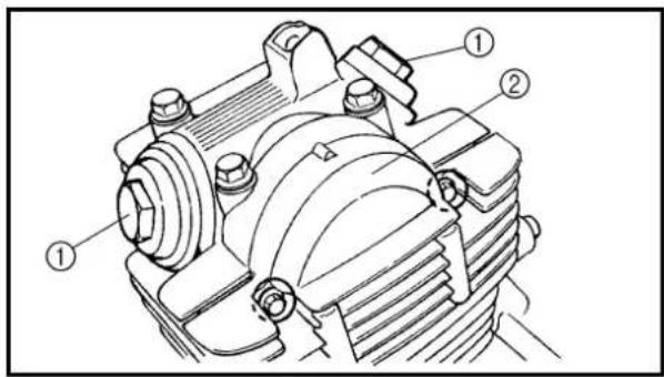
text_image
Technical diagram of a mechanical assembly with numbered components labeled ①, ②, and ①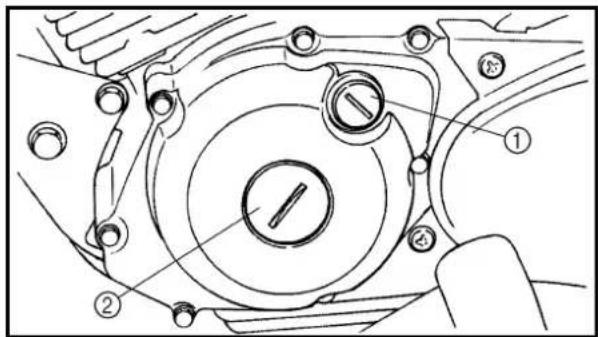
text_image
Technical diagram of a mechanical assembly with numbered components, likely for assembly or maintenance instructions.10.Apply:
• Engine oil On camshaft.
11.Install:
- Tappet cover ① 18 Nm (1.8 m · kg, 13 ft · lb) - Cylinder head side cover ② 10 Nm (1.0 m · kg, 7.2 ft · lb)
12.Install:
- Timing mark accessing screw ① - Crankshaft end accessing screw ② - 7 Nm (0.7 m · kg, 5.1 ft · lb)
13. Install:
- Spark plug 13 Nm (1.3 m · kg, 9.4 ft · lb) - Engine bracket 40 Nm (4.0 m · kg, 29 ft · lb)
9. Contrôler:
Extent of removal: ① Camshaft removal ② Rocker arm removal
| Extent of removal Order Part name Q'ty Remarks | ||||
| Preparation for removal Cylinder head Refer to "CYLINDER HEAD" section. | ||||
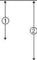 | 1 Camshaft bearing holder 12 Intake rocker arm shaft 13 Exhaust rocker arm shaft 14 Camshaft 1 Refer to "REMOVAL POINTS".5 Intake rocker arm 16 Exhaust rocker arm 1 | Refer to "REMOVAL POINTS". | ||
text_image
Technical diagram of a mechanical device with labeled parts ① and ②REMOVAL POINTS
Rocker arm shaft
- Remove:
- Rocker arm shafts
NOTE:
Use a slide hammer bolt ① and weight ② to slide out the rocker arm shafts.

Small slide hammer set:
YU-1083-A
Slide hammer bolt:
90890-01085
Weight:
90890-01084
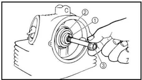
text_image
Technical diagram of a mechanical assembly with numbered components, likely illustrating a turning or disassembly process.Camshaft
- Remove:
. Camshaft ①
. Camshaft bearing ②
NOTE:
Screw in a suitable length of 8 mm bolt ③ into the threaded end of the camshaft and pull out the camshaft.
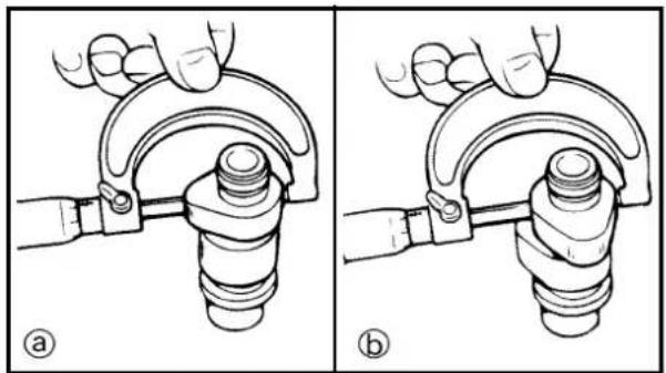
natural_image
Two diagrams showing hand positioning of a mechanical clamp or spring, labeled (a) and (b), with no text or symbols present.INSPECTION
Camshaft
- Inspect:
- Cam lobes Pitting/scratches/blue discoloration → Replace.
- Measure:
- Cam lobes length ⓐ and ⓑ Out of specification → Replace.

Cam lobes length limit:
Intake:
① 25.851 mm (1.0178 in)
⑥ 21.165 mm (0.8333 in)
Exhaust:
① 25.811 mm (1.0162 in)
⑥ 21.020 mm (0.8276 in)
PIÈCES À DÉPOSER
Axes de culbuteur
- Déposer:
- Axes de culbuteur
N.B.:
Dimensions limites de came:
Admission:
① 25,851 mm (1,0178 in)
⑥ 21,165 mm (0,8333 in)
Échappement:
① 25,811 mm (1,0162 in)
⑥ 21,020 mm (0,8276 in)
Nockenwelle
- Demontieren:
a 25,811 mm
⑥ 21,020 mm
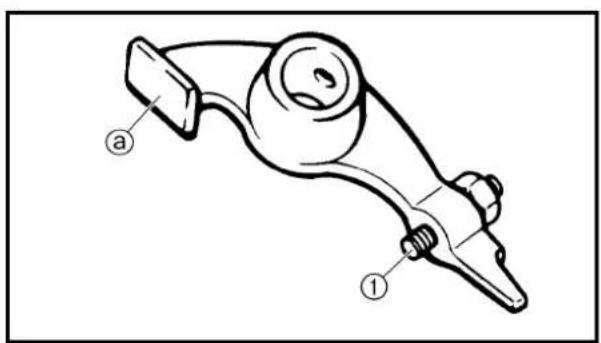
text_image
Technical diagram of a mechanical linkage component with labeled parts (a) and (1)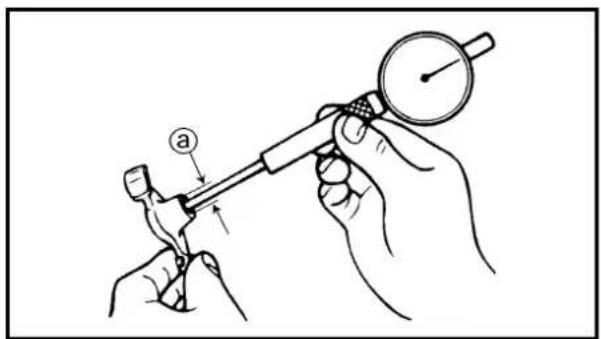
text_image
Diagram showing a hand using a dial indicator to measure a tool, with labeled component 'a' and directional arrow.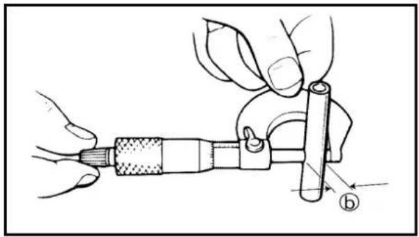
natural_image
Illustration of hands using a micrometer to measure a cylindrical tool (no text or symbols visible)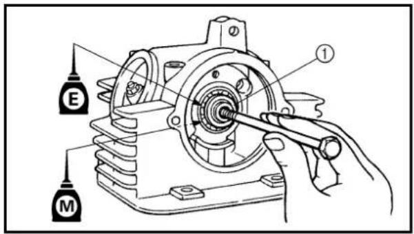
text_image
Technical diagram of a mechanical assembly with labeled parts E and M, showing a hand operating a shaft.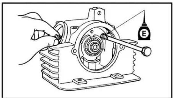
natural_image
Technical line drawing of a mechanical assembly with a hand operating a shaft and a labeled component (E) attached to a housing (no text or symbols present)Rocker arms and rocker arm shafts
1. Inspect:
- Cam lobe contact surface ⓐ
- Adjuster surface ①
Wear/pitting/scratches/blue discoloration → Replace.
Measurement steps:
- Measure the inside diameter ⓐ of the rocker arm holes. Out of specification → Replace.

Inside diameter (rocker arm):
10.000 \~ 10.015 mm
(0.3937 \~ 0.3943 in)
- Measure the outside diameter ⑥ of the rocker arm shafts. Out of specification → Replace.
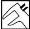
Outside diameter
(rocker arm shaft):
9.981 \~ 9.991 mm
(0.3930 \~ 0.3933 in)
ASSEMBLY AND INSTALLATION
1. Apply:
- Molybdenum disulfide oil (onto the camshaft cam lobe and rocker arm hole) - Engine oil (onto the camshaft bearing)
2. Install:
- Rocker arms
- Camshaft ①
3. Apply:
• Engine oil (onto the rocker arm shaft)
4. Install:
- Rocker arm shaft
text_image
Technical diagram of a mechanical assembly with labeled parts ① and ②, including a belt weight indicator.5. Install:
- Camshaft bearing holder ①
- Bolt ②

10 Nm (1.0 m · kg, 7.2 ft · lb)
text_image
1 2 3 New 6 7 M 4 5 M M NewExtent of removal:
① Valves and valve springs removal
| Extent of removal Order Part name Q'ty Remarks | |||
| Preparation for removal Cylinder | VALVES AND VALVE SPRINGS REMOVALhead Refer to "CYLINDER HEAD" section.Camshaft and rocker arms Refer to "CAMSHAFT AND ROCKER ARMS" section. | ||
| 1 | 1 Valve cotter 42 Valve spring retainer 23 Valve spring 24 Intake valve 15 Exhaust valve 26 Valve stem seal 27 Valve spring seat 2 | Refer to "REMOVAL POINTS". | |
SOUPAPES ET RESSORTS DE SOUPAPE

text_image
Technical diagram of a mechanical assembly with labeled parts ① and ②
text_image
Technical diagram of a mechanical assembly with labeled parts ① and ②, showing internal components and motion indicators.REMOVAL POINTS
Valve
1. Check:
- Valve sealing
Leakage at the valve seat → Inspect the valve face, valve seat and valve seat width.
Checking steps:
- Pour a clean solvent ① into the intake and exhaust ports.
- Check that the valve seals properly. There should be no leakage at the valve seat ②.
2. Remove:
- Valve cotters ①
NOTE:
Attach a valve spring compressor ② between the valve spring retainer and the cylinder head to remove the valve cotters.
Valve spring compressor: YM-4019/90890-04019
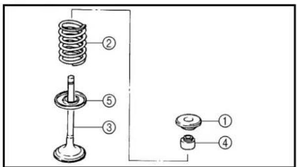
text_image
Technical diagram of a mechanical assembly with numbered components for identification3. Remove:
- Valve spring retainer ①
- Valve spring ②
- Valve ③
- Valve stem seal ④
- Valve spring seat ⑤
NOTE:
Identify the position of each part very carefully so that it can be reinstalled in its original place.
PIÈCES À DÉPOSER
Valve
1. Contrôler:
natural_image
Technical line drawing of a mechanical gauge or dial indicator with no visible text or symbols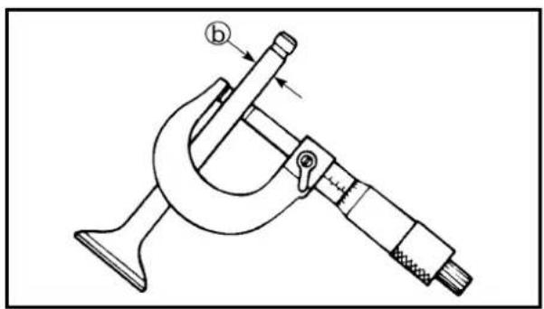
natural_image
Technical line drawing of a micrometer caliper (no text or symbols present)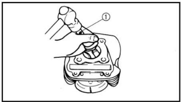
text_image
Technical diagram showing a mechanical assembly with labeled component ①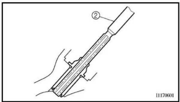
text_image
② 11170601INSPECTION
Valve
- Measure:
• Stem-to-guide clearance
Stem-to-guide clearance = valve guide inside diameter ① – valve stem diameter ②
Out of specification → Replace the valve guide.

Clearance (stem to guide):
Intake:
0.010 \~ 0.037 mm
(0.0004 \~ 0.0015 in)
Exhaust:
0.025 \~ 0.052 mm
(0.0010 \~ 0.0020 in)
- Replace:
- Valve guide
Replacement steps:
NOTE:
To ease guide removal, installation and to maintain correct fit heat the cylinder head in an over to 100 °C (212 °F).
- Remove the valve guide using a valve guide remover ①.
• Install the new valve guide using a valve guide remover and valve guide installer.
• After installing the valve guide, bore the valve guide using a valve guide reamer ② to obtain proper stem-to-guide clearance.

Valve guide remover:
YM-4097/90890-04097
Valve guide installer:
YM-4098/90890-04098
Valve guide reamer:
YM-04099/90890-04099
NOTE:
After replacing the valve guide reface the valve seat.
INSPECTION
Soupape
- Mesurer:
- Valve face Pitting/wear → Grind the face.
- Valve stem end Mushroom shape or diameter larger than the body of the stem → Replace.
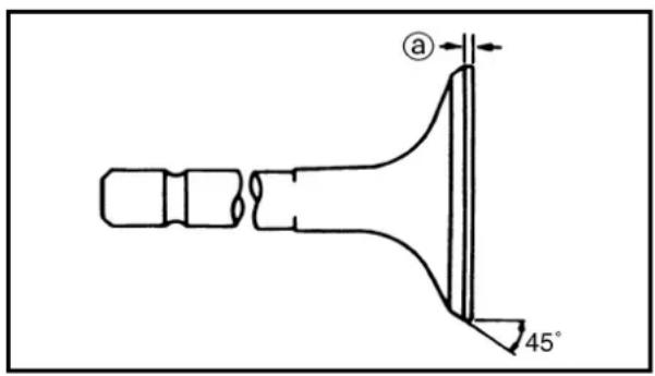
text_image
a 45°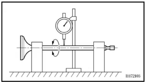
natural_image
Technical diagram of a mechanical testing setup with a dial indicator and rotating component (no text or symbols)4. Measure:
- Margin thickness ⓐ Out of specification → Replace.

Margin thickness:
Intake:
0.4 \~ 0.8 mm
(0.0157 \~ 0.0315 in)
Exhaust:
0.8 \~ 1.2 mm
(0.0315 \~ 0.0472 in)
5. Measure:
- Runout (valve stem) Out of specification → Replace.

Runout limit: 0.01 mm (0.0004 in)
NOTE:
- When installing a new valve always replace the guide.
- If the valve is removed or replaced always replace the oil seal.
6. Eliminate:
• Carbon deposits (from the valve face and valve seat)
7. Inspect:
- Valve seats Pitting/wear → Reface the valve seat.
SOUPAPES ET RESSORTS DE SOUPAPE VENTILE UND VENTILFEDERN
ENG

3. Examiner:
Out of specification → Reface the valve seat.

Valve seat width:
Intake:
0.9 \~ 1.1 mm (0.0354 \~ 0.0433 in)
Exhaust:
0.9 \~ 1.1 mm (0.0354 \~ 0.0433 in)
Measurement steps:
- Apply Mechanic's blueing dye (Dykem) ⑥ to the valve face.
• Install the valve into the cylinder head. - Press the valve through the valve guide and onto the valve seat to make a clear pattern.
- Measure the valve seat width. Where the valve seat and valve face made contact, blueing will have been removed.
- If the valve seat is too wide, too narrow, or the seat is not centered, the valve seat must be refaced.
9. Lap:
- Valve face
- Valve seat
NOTE:
After refacing the valve seat or replacing the valve and valve guide, the valve seat and valve face should be lapped.
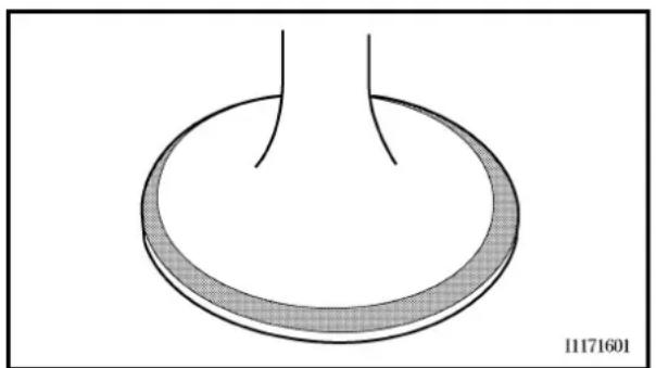
natural_image
Simple line drawing of a circular object with a shaded ring, no text or symbols presentLapping steps:
- Apply a coarse lapping compound to the valve face.
CAUTION:
Do not let the compound enter the gap between the valve stem and the valve guide.
- Apply molybdenum disulfide oil to the valve stem.
SOUPAPES ET RESSORTS DE SOUPAPE VENTILE UND VENTILFEDERN
ENG

8. Mesurer:
text_image
Diagram showing a mechanical device labeled 'M' being inserted into a housing, and a hand inserting a component into a tank.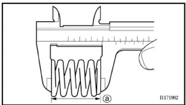
text_image
I1171902 a• Install the valve into the cylinder head.
- Turn the valve until the valve face and valve seat are evenly polished, then clean off all of the compound.
NOTE:
For best lapping results, lightly tap the valve seat while rotating the valve back and forth between your hands.
- Apply a fine lapping compound to the valve face and repeat the above steps.
NOTE:
After every lapping operation be sure to clean off all of the compound from the valve face and valve seat.
- Apply Mechanic's blueing dye (Dykem) to the valve face.
• Install the valve into the cylinder head. - Press the valve through the valve guide and onto the valve seat to make a clear pattern.
- Measure the valve seat width again. If the valve seat width is out of specification, reface and re-lap the valve seat.
Valve spring
- Measure:
• Valve spring free length ⓐ
Out of specification → Replace.

Free length (valve spring):
Intake:
32.55 mm (1.28 in)
Exhaust:
32.55 mm (1.28 in)
• Compressed spring force ⓐ
Out of specification → Replace.
⑥ Installed length

Compressed spring force:
Intake:
14.0 \~ 16.1 kg at 25.6 mm
(30.86 \~ 35.49 lb at 1.01 in)
Exhaust:
14.0 \~ 16.1 kg at 25.6 mm
(30.86 \~ 35.49 lb at 1.01 in)
3. Measure:
• Spring tilt ⓐ
Out of specification → Replace.

Spring tilt limit:
Intake:
2.5°/1.4 mm (0.06 in)
Exhaust:
2.5°/1.4 mm (0.06 in)
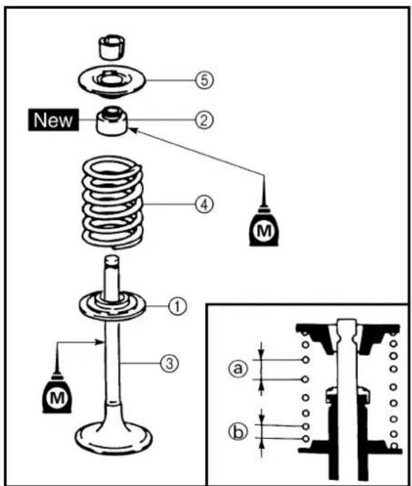
text_image
New ① ② ③ ④ ⑤ M a bASSEMBLY AND INSTALLATION
Valve
1. Apply:
• Molybdenum disulfide oil (onto the valve stem and valve stem seal)
2. Install:
- Valve spring seats ①
- Valve stem seals ②
- Valves ③
• Valve springs ④ - Valve spring retainers ⑤
New
NOTE:
- Make sure that each valve is installed in its original place.
• Install the valve springs with the larger pitch @ facing upwards.
⑥ Smaller pitch
SOUPAPES ET RESSORTS DE SOUPAPE VENTILE UND VENTILFEDERN
ENG

2. Mesurer:
- Force de ressort comprimé ⓐ
text_image
Technical diagram of a mechanical assembly with labeled parts ① and ②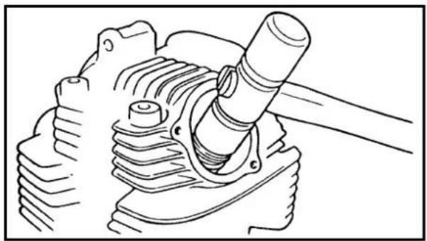
natural_image
Technical line drawing of a mechanical assembly with a cylindrical component inserted into a housing (no text or symbols)- Install:
- Valve cotters ①
NOTE:
While compressing the valve spring with a valve spring compressor ②, install the valve cotters.

Valve spring compressor: YM-4019/90890-04019
- To secure the valve cotters onto the valve stem, lightly tap the valve tip with a piece of wood.
CAUTION: Hitting the valve tip with excessive force could damage the valve.
SOUPAPES ET RESSORTS DE SOUPAPE VENTILE UND VENTILFEDERN
ENG

3. Installer:
text_image
Exploded view diagram of a mechanical assembly with labeled parts including engine, piston, crankshaft, and motor componentsExtent of removal:
① Cylinder removal
② Piston removal
| Extent of removal Order | Cylinder | name Q'ty Remarks | CYLINDER AND PISTON REMOVALhead Refer to “CYLINDER HEAD” section. | |||
| Preparation for removal | ||||||
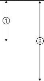 | 1 | Exhaust timing chain guide 1 | 1/1 | |||
| 2 | Cylinder/O-ring | |||||
| 3 | Dowel pin 2 | |||||
| 4 | Gasket | 1 | ||||
| 5 | Piston pin clip 2 | |||||
| 7 | Piston | Refer to “REMOVAL POINTS”.6 Piston pin 1 | ||||
| 8 | Piston ring set | 1 | Refer to “REMOVAL POINTS”. | |||
CYLINDRE ET PISTON

text_image
Technical diagram showing a mechanical assembly with numbered components labeled ①, ②, and ③.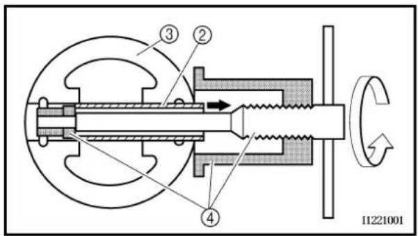
text_image
③ ② ④ 11221001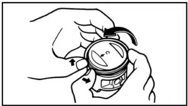
natural_image
Illustration of hands holding a small container with arrows indicating rotation or movement (no text or symbols)REMOVAL POINTS
Piston
-
Remove:
-
Piston pin clips ①
- Piston pin ②
- Piston ③
NOTE:
- Before removing the piston pin clip, cover the crankcase opening with a clean towel or rag to prevent the clip from falling into the crank-case cavity.
- Before removing each piston pin, deburr the clip groove and pin hole area. If the piston pin groove is deburred and the piston pin is still difficult to remove, use the piston pin puller ④.
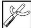
Piston pin puller set: YU-1304/90890-01304
CAUTION:
Do not use a hammer to drive the piston pin out.
Piston ring
- Remove:
- Piston rings
NOTE:
Spread the end gaps apart while at the same time lifting the piston ring over the top of the piston crown, as shown in the illustration.
INSPECTION
Cylinder and piston
- Inspect:
- Cylinder and piston walls Vertical scratches → Replace cylinder and piston.
PIÈCES À DÉPOSER
Piston
1. Déposer:
- Piston-to-cylinder clearance
| Piston-to-cylinder clearance measurement steps:1st step:Measure the cylinder bore “C” with the cylinder bore gauge.NOTE:Measure the cylinder bore “C” in parallel to and at right angles to the crankshaft. Then, find the average of the measurements. | |
| Cylinder bore “C” | 54.000 ~ 54.019 mm(2.126 ~ 2.127 in) |
| Taper limit “T” 0.05 mm (0.002 in) | |
| Out of round “R” 0.05 mm (0.002 in) | |
| “C” = maximum of D1 ~ D6 | |
| “T” = maximum of D1, or D2 – maximum of D5 or D6 | |
| “R” = maximum of D1, D3 or D5 – minimum of D2, D4 or D6 | |
| · If out of specification, replace the cylinder, and replace the piston and piston rings as set.2nd step:· Measure the piston skirt diameter “P” with a micrometer.@ 5 mm (0.20 in) from the piston bottom edge. | |
| Piston size P | |
| Standard | 53.977 ~ 53.996 mm(2.1251 ~ 2.1258 in) |
| · If out of specification, replace the piston and piston rings as a set.3rd step:· Calculate the piston-to-cylinder clearance with following formula. | |
| Piston-to-cylinder clearance = Cylinder bore “C” – Piston skirt diameter “P” | |
 | Piston-to-cylinder clearance:0.020 ~ 0.026 mm(0.0008 ~ 0.0010 in): 0.15 mm (0.006 in) |
2. Mesurer:
- If out of specification, replace the cylinder, and replace the piston and piston rings as a set.
Piston pin
1. Inspect:
- Piston pin Blue discoloration/grooves → Replace, then inspect the lubrication system.
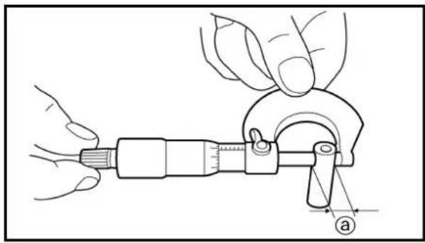
natural_image
Illustration of a hand using a micrometer to measure a tool, with no visible text or symbols
text_image
Technical diagram showing hands operating a mechanical device with labeled component 'b'2. Measure:
- Piston pin-to-piston clearance
| Measurement steps:Measure the piston pin outside diameter a.If out of specification, replace the piston pin | |
| Outside diameter (piston pin):14.991 ~ 15.000 mm(0.5902 ~ 0.5906 in):14.971 mm (0.5894 in) | |
| Measure the piston inside diameter b.If out of specification, replace the piston. | |
| Inside diameter (piston):15.002 ~ 15.013 mm(0.5906 ~ 0.5911 in):15.043 mm (0.5922 in) | |


natural_image
Line drawing of two hands holding a circular object, no text or symbols presentPiston ring
1. Measure:
- Ring side clearance
Use a feeler gauge.
Out of specification → Replace the piston and rings as a set.
NOTE:
Clean carbon from the piston ring grooves and rings before measuring the side clearance.
| Side clearance: | ||
| Standard | ||
| Top ring | 0.035 ~ 0.090 mm(0.0014 ~ 0.0035 in) | 0.12 mm(0.0047 in) |
| 2nd ring | 0.020 ~ 0.060 mm(0.0008 ~ 0.0024 in) | 0.12 mm(0.0047 in) |
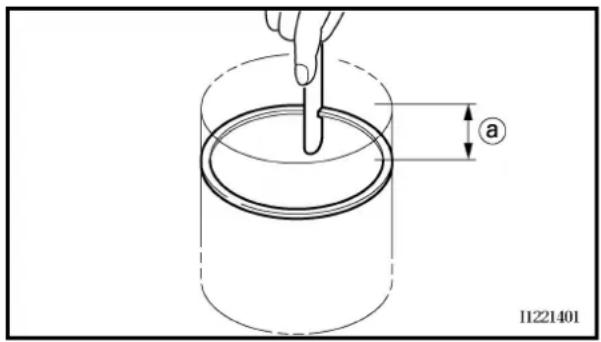
text_image
a 112214012. Position:
- Piston ring (in cylinder)
NOTE:
Insert a ring into the cylinder and push it approximately 40 mm (1.57 in) into the cylinder. Push the ring with the piston crown so that the ring will be at a right angle to the cylinder bore.
(a) 40 mm (1.57 in)
3. Measure:
- Ring end gap
Out of specification → Replace.
NOTE:
You cannot measure the end gap on the expander spacer of the oil control ring. If the oil control ring rails show excessive gap, replace all three rings.
 | End gap: | |
| Standard | ||
| Top ring | 0.15 ~ 0.30 mm(0.006 ~ 0.012 in) | 0.4 mm(0.016 in) |
| 2nd ring | 0.30 ~ 0.45 mm(0.012 ~ 0.018 in) | 0.55 mm(0.022 in) |
| Oil ring | 0.20 ~ 0.70 mm(0.01 ~ 0.03 in) | — |
Segment de piston
1. Mesurer:
natural_image
Technical line drawing of a mechanical component with labeled parts (a and c), no readable text or symbols beyond labels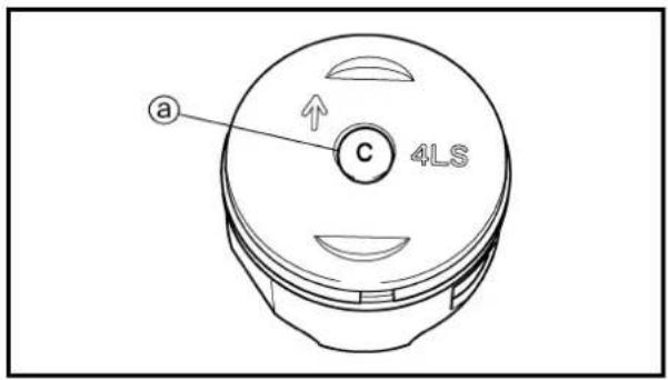
text_image
a C 4LSCombination of piston and cylinder
- Check:
- Cylinder mark ⓐ
| Cylinder mark @ Cylinder size | |
| A | 54.000 ~ 54.003 mm(2.1260 ~ 2.1261 in) |
| B | 54.004 ~ 54.007 mm(2.1261 ~ 2.1263 in) |
| C | 54.008 ~ 54.011 mm(2.1263 ~ 2.1264 in) |
| D | 54.012 ~ 54.015 mm(2.1265 ~ 2.1266 in) |
| E | 54.016 ~ 54.019 mm(2.1266 ~ 2.1267 in) |
- Check:
- Piston mark ⓐ
| Cylinder mark ⓐ (color) | Piston size |
| A (red) | 53.977 ~ 53.980 mm(2.1251 ~ 2.1252 in) |
| B (orange) | 53.981 ~ 53.984 mm(2.1252 ~ 2.1254 in) |
| C (green) | 53.985 ~ 53.988 mm(2.1254 ~ 2.1255 in) |
| D (purple) | 53.989 ~ 53.992 mm(2.1255 ~ 2.1257 in) |
| E (blue) | 53.993 ~ 53.996 mm(2.1257 ~ 2.1258 in) |
- Combination:
- Combine the piston and cylinder by the following chart.
| Cylinder mark Piston mark (color) | |
| A A (red) | |
| B B (orange) | |
| C C (green) | |
| D D (purple) | |
| E E (blue) | |
NOTE:
When you purchase a cylinder, you cannot designate its size. Choose the piston that matches the above chart.
natural_image
Simple line drawing of a loop with an upward arrow labeled 'UP' and a small label 'NE' at the end (no text or symbols beyond labels)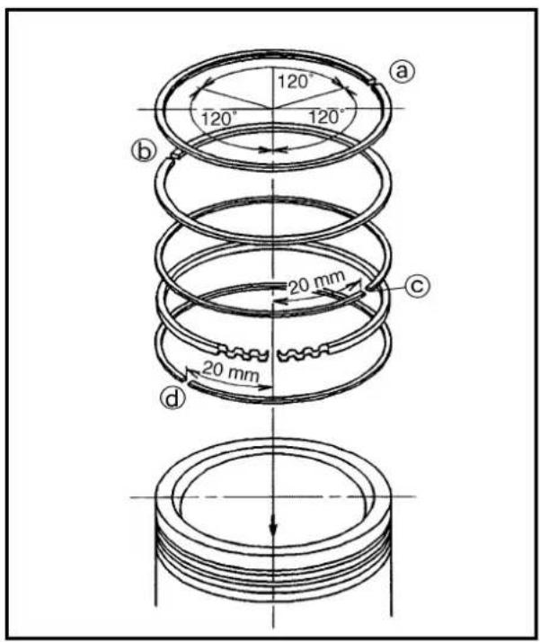
text_image
120° 120° 120° 120° 20 mm 20 mm a b c d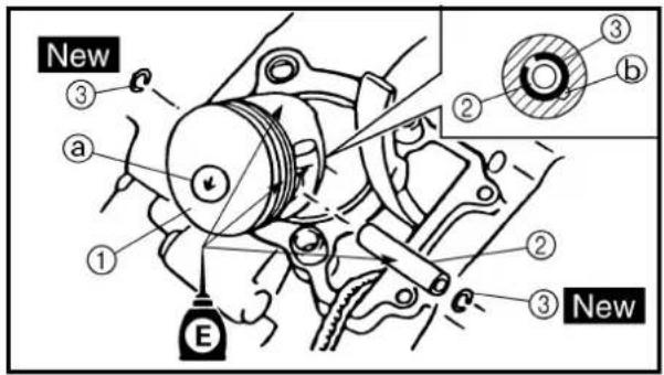
text_image
New ③ a ① ② ③ b ② ③ New EASSEMBLY AND INSTALLATION
Piston ring and piston
- Install:
- Piston rings
(onto the piston)
NOTE:
- Be sure to install the 2nd piston ring so that the manufacturer's mark or number are located on the upper side of the ring.
- Lubricate the piston and piston rings liberally with engine oil.
-
Position:
-
Top ring
- 2nd ring
• Oil ring
Offset the piston ring end gaps as shown.
①:Top ring end
⑥:2nd ring end
©:Oil ring end (upper)
(d):Oil ring end (lower)
- Install:
Piston ①
• Piston pin ②
• Piston pin clips ③
New
NOTE:
- Apply engine oil onto the piston pin, piston rings and piston.
- Be sure that the arrow mark @ on the piston points to the exhaust side of the engine.
- Before installing the piston pin clip, cover the crankcase with a clean rag to prevent the piston pin clip from falling into the crankcase.
-
When removing the piston pin clip, pop it out using the small opening ⑥.
-
Lubricate:
• Piston
• Piston rings
• Inside of cylinder
NOTE:
Apply a liberal coating of engine oil.
ASSEMBLAGE ET REPOSE
Segments et piston
- Installer:
text_image
Technical diagram showing mechanical assembly with labeled component ① and directional arrows indicating movement or forceCylinder
- Install:
• Dowel pins ①
• Gasket (cylinder) ②
New
- Install:
. O-ring New
• Cylinder ①
• Exhaust timing chain guide
CAUTION:
• Install the cylinder with one hand while compressing the piston rings with the other hand.
• Pass the timing chain through the cylinder timing chain cavity.
- Be careful not to damage the timing chain guide during installation.
NOTE:
After installing, check the smooth movement of the piston.
Cylindre
1. Installer:
• Goujons ①
• Joint (cylindre) ②
New
2. Installer:
• Joint torique
New
•Cylindre ①
CLUTCH AND PRIMARY DRIVEN GEAR
EC498000
CLUTCH PLATE AND FRICTION PLATE

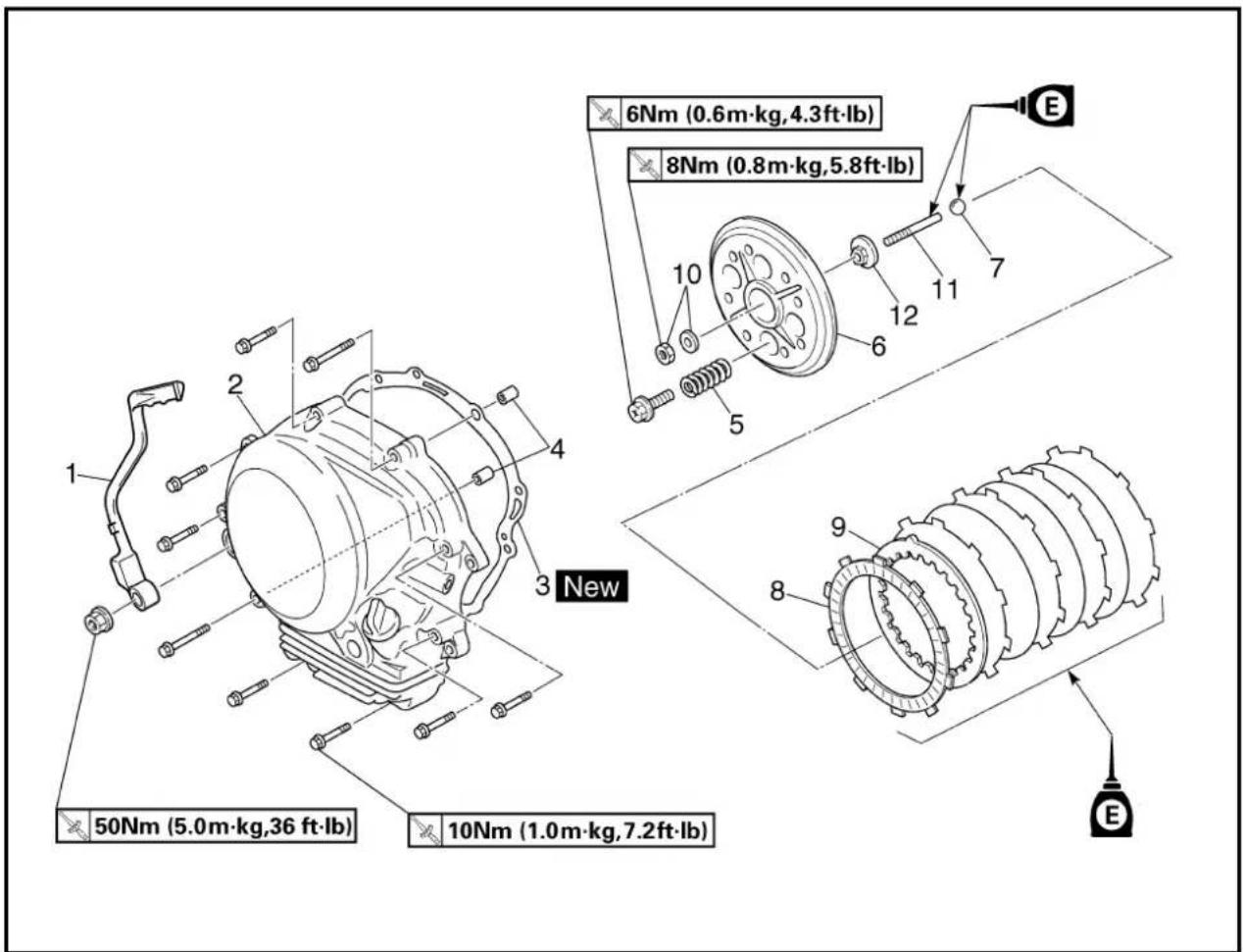
text_image
6Nm (0.6m·kg,4.3ft·lb) 8Nm (0.8m·kg,5.8ft·lb) 10 12 7 E New 50Nm (5.0m·kg,36 ft·lb) 10Nm (1.0m·kg,7.2ft·lb)Extent of removal: ① Clutch plate and friction plate removal
| Extent of removal Order Part name Q'ty Remarks | ||||
| Preparation for removal | Drain the | CLUCTH PLATE AND FRIC-TION PLATE REMOVALengine oil. Refer to "ENGINE OIL REPLACEMENT"section in the CHAPTER 3.Engine skidplate Refer to "ENGINE REMOVAL" section. | ||
| 1 | 1 Kickstarter crank 12 Right crankcase cover 13 Gasket 14 Dowel pin 25 Clutch spring 46 Pressure plate 17 Ball8 Friction plate9 Clutch plate10 Nut/washer11 Push rod 112 Push plate 1 | |||
EMBRAYAGE ET PIGNON MENÉ PRIMAIRE
DISQUES D'EMBRAYAGE ET DE FRICTION

① Primary driven gear removal
② Primary drive gear removal
| Extent of removal Order Part name Q'ty Remarks | ||||
| PRIMARY DRIVEN GEAR REMOVAL1 Nut (clutch boss) 12 Lock washer 13 Clutch boss 14 Thrust plate 15 Primary driven gear 16 Thrust plate 17 Conical spring washer 18 Nut (primary drive gear) 19 Primary drive gear 110 Straight key | Use special tool.Refer to “REMOVAL POINTS”.Refer to “REMOVAL POINTS”. | |||
EMBRAYAGE ET PIGNON MENÉ PRIMAIRE KUPPLUNG UND PRIMÄRABTRIEBSZAHNRAD
ENG

PIGNON MENÉ PRIMAIRE
text_image
1 2 E 3 4 New New 5 LSExtent of removal:
① Push lever removal
| Extent of removal Order Part name Q'ty Remarks | ||||
| [CBH4] | PUSH LEVER REMOVAL1 Clutch cable 12 Push lever 13 Spring 14 Circlip 15 Oil seal | |||
| 1 | ||||
EMBRAYAGE ET PIGNON MENÉ PRIMAIRE KUPPLUNG UND PRIMÄRABTRIEBSZAHNRAD
ENG

LEVIER DE POUSSÉE
text_image
Technical diagram of a mechanical assembly with numbered components, likely illustrating a gear or cam mechanism.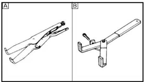
natural_image
Two technical line drawings of metal clamps labeled A and B, showing different angles and mounting brackets (no text or symbols present)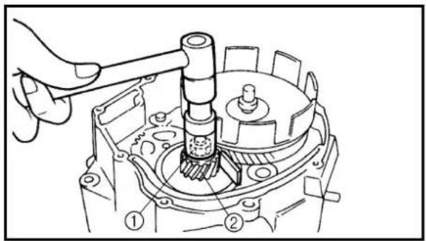
text_image
Technical diagram of a mechanical assembly with numbered parts, likely illustrating gear or gear mechanism.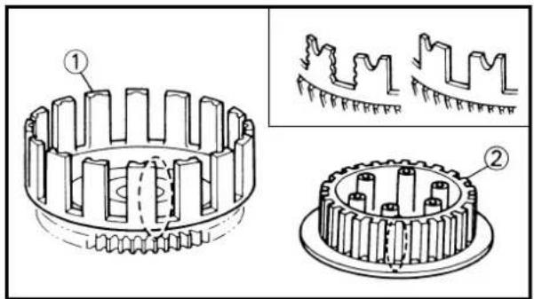
text_image
Technical diagram showing gear meshing with labeled components and two detailed views of the gear structure.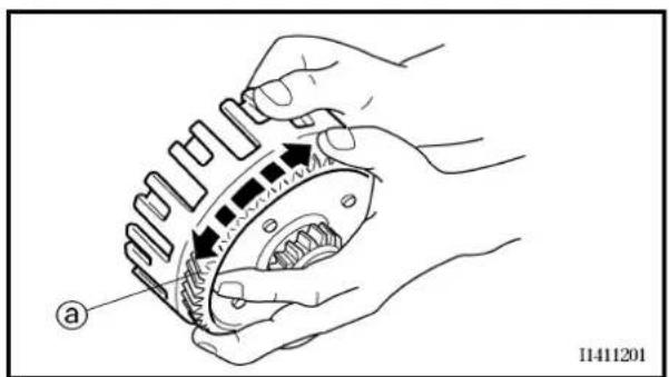
text_image
a 11411201EC493000
REMOVAL POINTS
Clutch boss
-
Remove:
-
Nut ①
- Lock washer
- Clutch boss ②
NOTE:
Straighten the lock washer tab and use the clutch holding tool ③ to hold the clutch boss.

Clutch holding tool: YM-91042/90890-04086
A For USA and CDN
B Except for USA and CDN
Primary drive gear
-
Remove:
-
Nut (primary drive gear) ①
• Primary drive gear ②
NOTE:
- Place a folded rag or aluminum plate between the teeth of the primary drive gear and primary driven gear.
• Take care not to damage the gear teeth.
EC494000
INSPECTION
EC484100
Clutch housing and boss
-
Inspect:
-
Clutch housing ① Cracks/wear/damage → Replace.
- Clutch boss ② Scoring/wear/damage → Replace.
EC484201
Primary driven gear
-
Check:
-
Circumferential play Free play exists → Replace.
- Gear teeth ⓐ Wear/damage → Replace.
EMBRAYAGE ET PIGNON MENÉ PRIMAIRE KUPPLUNG UND PRIMÄRABTRIEBSZAHNRAD
ENG

PIÈCES À DÉPOSER
Noix d'embrayage
1. Déposer:
natural_image
Illustration of a hand using a caliper to adjust a spring (no text or symbols present)EC484400
Clutch spring
1. Measure:
- Clutch spring free length ⓐ Out of specification → Replace springs as a set.

Clutch spring free length:
33 mm (1.30 in)
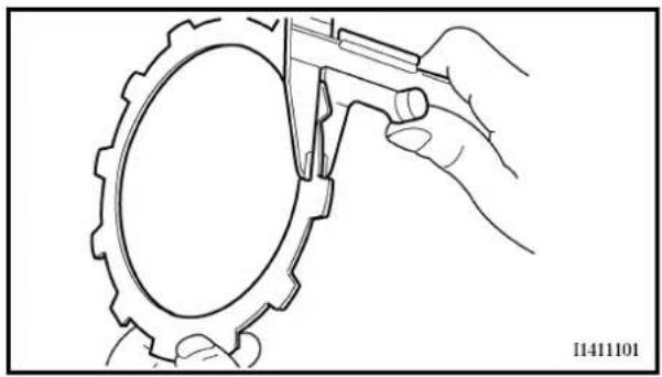
natural_image
Line drawing of hands using a tool to cut a gear (no text or symbols)EC484500
Friction plate
1. Measure:
- Friction plate thickness Out of specification → Replace friction plate as a set. Measure at all four points.

Friction plate thickness:
2.92 \~ 3.08 mm
(0.115 \~ 0.121 in)
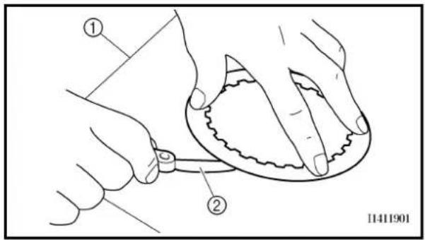
text_image
Technical diagram showing two hands operating a circular object with labeled parts, including numbered annotations.EC484600
Clutch plate
1. Measure:
- Clutch plate warpage Out of specification → Replace clutch plate as a set. Use a surface plate ① and thickness gauge ②.
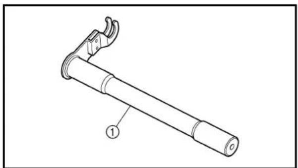
natural_image
Technical line drawing of a mechanical lever or support device with labeled part (1), no text or symbols present
Warp limit: 0.2 mm (0.008 in)
Push lever
1. Inspect:
- Push lever ① Wear/damage → Replace.
EMBRAYAGE ET PIGNON MENÉ PRIMAIRE KUPPLUNG UND PRIMÄRABTRIEBSZAHNRAD
ENG

Ressort d'embrayage
1. Mesurer:
text_image
Technical diagram showing a threaded rod and a separate circular component with labeled parts ① and ②.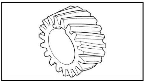
natural_image
Technical line drawing of a gear with evenly spaced teeth (no text or symbols)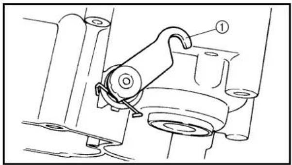
natural_image
Technical line drawing of a mechanical assembly with labeled component (no text or symbols present)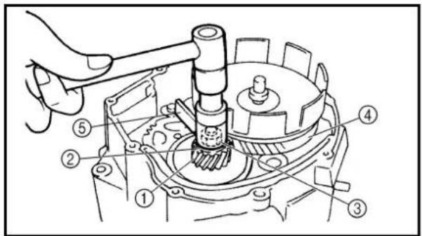
text_image
Technical diagram of a mechanical assembly with numbered components for identification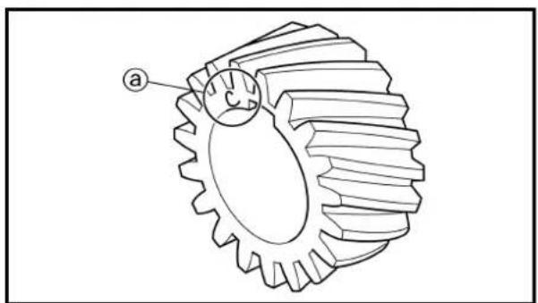
natural_image
Technical line drawing of a gear with labeled point 'a' (no text or symbols beyond label)Push rod
-
Inspect:
-
Push rod 1 ①
- Ball ②
Wear/damage/bend → Replace.
Primary drive gear
- Inspect:
• Primary drive gear Wear/damage → Replace.
EC495000
ASSEMBLY AND INSTALLATION
Push lever
- Install:
- Push lever ①
NOTE:
- Apply the lithium soap base grease on the oil seal lip.
- Apply the engine oil on the push lever.
Primary drive gear
- Install:
• Straight key
• Primary drive gear ①
.Washer ②
• Nut (primary drive gear) ③
70 Nm (7.0 m · kg, 50 ft · lb)
• Primary driven gear ④
NOTE:
• Install the primary drive gear with the stamp
Ⓐ facing out.
- Place a folded rag or aluminum plate ⑤ between the teeth of the primary drive gear and primary driven gear.
EMBRAYAGE ET PIGNON MENÉ PRIMAIRE KUPPLUNG UND PRIMÄRABTRIEBSZAHNRAD
ENG

Tige de commande
- Examiner:
text_image
Technical diagram of a mechanical assembly with numbered parts for identification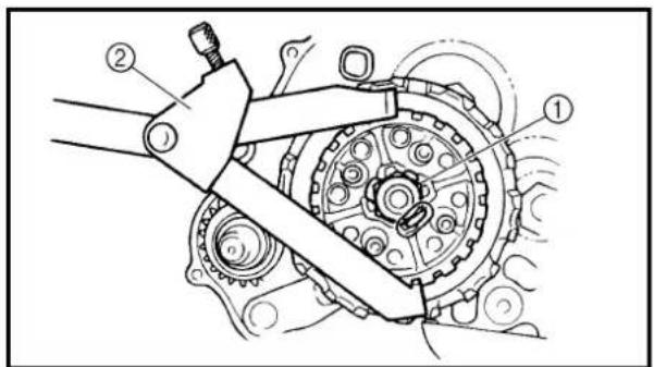
text_image
Technical diagram of a mechanical assembly with numbered components, likely illustrating a gear or cam mechanism.
natural_image
Two technical line drawings of metal clamps, labeled A and B, showing different angles and mounting brackets (no text or symbols present)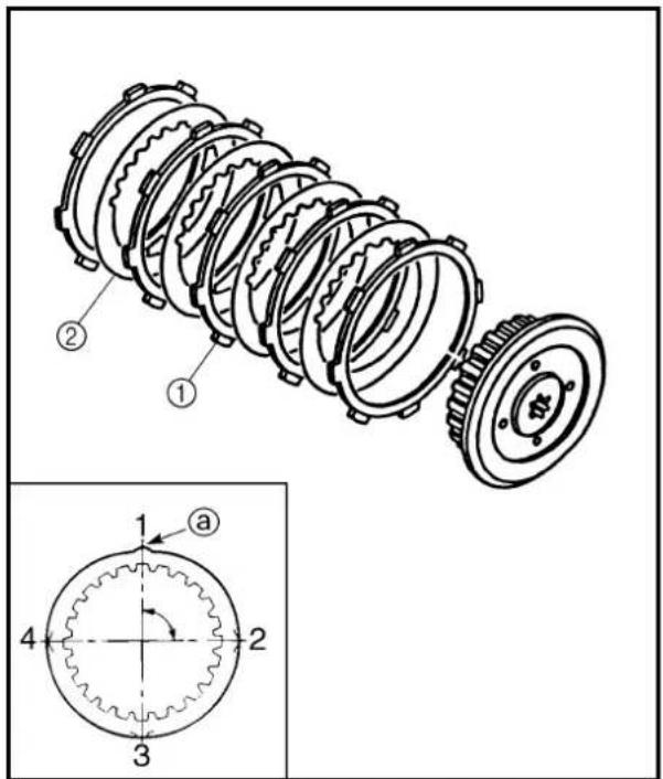
text_image
Technical diagram of a mechanical clutch assembly with numbered components and a detailed cross-section view labeled 1-4.Clutch
1. Install:
• Conical spring washer ①
- Thrust plate ②
• Primary driven gear ③
• Thrust plate ④
- Clutch boss ⑤
2. Install:
- Lock washer New
• Nut (clutch boss) ①
60 Nm (6.0 m · kg, 43 ft · lb)
NOTE:
Use the clutch holding tool ② to hold the clutch boss.

Clutch holding tool: YM-91042/90890-04086
A For USA and CDN
B Except for USA and CDN
3. Bend:
- Lock washer tab
4. Install:
• Friction plate ①
- Clutch plate ②
NOTE:
• Install the clutch plates and friction plates alternately on the clutch boss, starting with a friction plate and ending with a friction plate.
- Apply the engine oil on the friction plates and clutch plates.
- Be sure to install a clutch plate with projection @ offset approximately 90^ from previous plates projection. Continue this procedure in a clockwise direction until all clutch plates are installed.
EMBRAYAGE ET PIGNON MENÉ PRIMAIRE KUPPLUNG UND PRIMÄRABTRIEBSZAHNRAD
ENG

Embrayage
1. Installer:
natural_image
Mechanical assembly diagram showing a hand turning a gear into a mechanical component with a labeled component E (no text or symbols beyond label)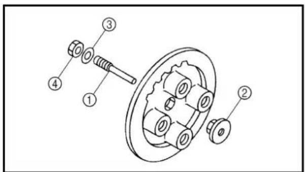
text_image
Technical diagram of a mechanical assembly with numbered parts for identification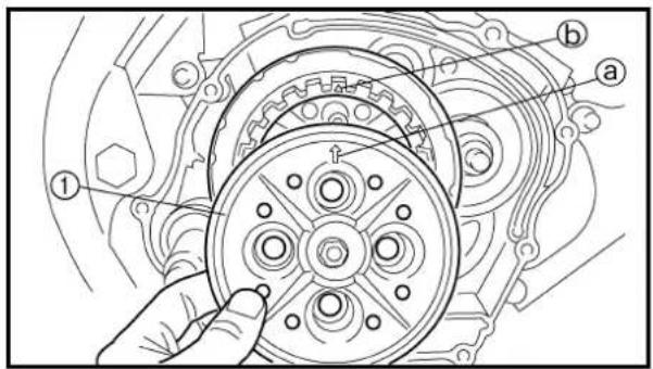
text_image
Technical diagram of a mechanical assembly with labeled parts (a, b) and numbered components (①, ②)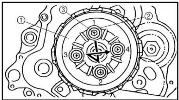
text_image
Technical diagram of a mechanical gear assembly with numbered components and directional arrows indicating motion or force.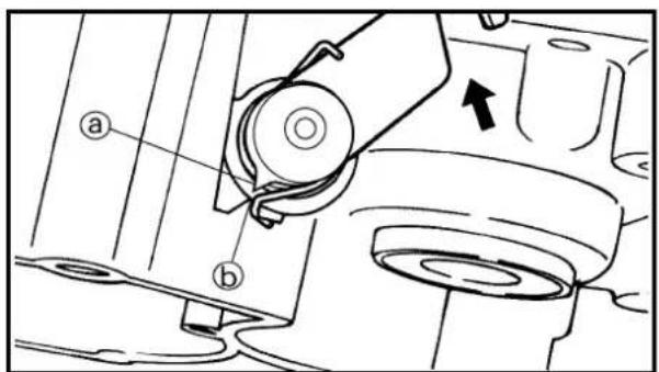
text_image
Technical diagram of a mechanical assembly with labeled parts (a) and (b), showing a component with an arrow indicating direction.- Install:
• Ball
NOTE:
Apply the engine oil on the ball.
- Install:
• Push rod 1 ①
- Push plate ②
.Washer ③
• Nut (push rod 1) ④
-
Install:
-
Pressure plate ①
- Clutch spring ②
• Bolt (clutch spring) ③
6 Nm (0.6 m · kg, 4.3 ft · lb)
NOTE:
- Align the arrow mark ⓐ on the pressure plate with the punched mark ⓑ on the clutch boss.
-
Tighten the bolts in stage, using a crisscross pattern.
-
Check:
- Push lever position
Push the push lever assembly in the arrow direction and make sure that the mach mark are aligned → adjust.
① Match mark on the push lever assembly
⑥ Match mark on the crankcase
EMBRAYAGE ET PIGNON MENÉ PRIMAIRE KUPPLUNG UND PRIMÄRABTRIEBSZAHNRAD
ENG

5. Installer:
• Bille
N.B.:
text_image
Technical diagram of a mechanical assembly with numbered components, likely illustrating a gear or valve mechanism.9. Adjust:
- Push lever position
Adjustment steps:
- Loosen the locknut ①.
- Turn the push rod 1 ② clockwise or counterclockwise to match alignment marks.
- Hold the push rod 1 to prevent it from moving and tighten the locknut to specification.
• Tighten the locknut ①.

Locknut: 8 Nm (0.8 m · kg, 5.8 ft · lb)
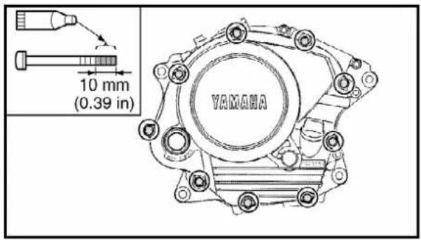
text_image
10 mm (0.39 in) YAMANA10. Install:
• Dowel pins
• Gasket (right crankcase cover)
New
• Right crankcase cover
• Bolts (right crankcase cover)
10 Nm (1.0 m · kg, 7.2 ft · lb)
NOTE:
- Apply Quick gasket ^® (YAMAHA Bond No.1215) to end of the right crankcase cover bolts, as shown.
- Tighten the bolts in stages, using a criss-cross pattern.

Quick gasket®: ACC-QUICK-GS-KT YAMAHA Bond No.1215: 90890-85505
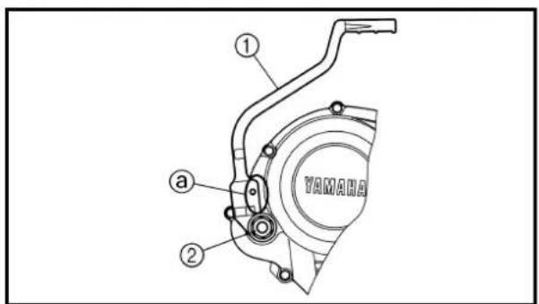
text_image
① ② a YAMAHA11. Install:
- Kickstarter crank ①
• Nut (kickstarter crank) ②
50 Nm (5.0 m · kg, 36 ft · lb)
NOTE:
Install the kickstarter crank so that there is 5 \~ 10 mm (0.2 \~ 0.4 in) ⓐ between the kickstarter crank and the right crankcase cover.
EMBRAYAGE ET PIGNON MENÉ PRIMAIRE KUPPLUNG UND PRIMÄRABTRIEBSZAHNRAD
ENG

9. Régler:
Extent of removal: ① Oil pump removal
| Extent of removal Order Part name Q'ty Remarks | ||||
| Preparation for removal | Clutch and primary drive gear Refer to “CLUTCH AND PRIMARY DRIVEN GEAR” section. | |||
| 1 | 1 Rotary filter 12 Oil pump drive gear 13 Oil pump assembly 14 Gasket 15 Oil strainer | |||
POMPE À HUILE

Extent of removal: ① Oil pump disassembly
| Extent of removal Order Part name Q'ty Remarks | |||
| 1 | OIL PUMP DISASSEMBLY1 Circlip 12 Oil pump driven gear 13 Conical spring washer 14 Circlip 15 Washer 16 Oil pump cover 17 Pin 28 Oil pump shaft 19 Pin 110 Inner rotor 111 Outer rotor 112 Oil pump housing 1 | ||
DÉMONTAGE DE LA POMPE À HUILE
- Oil pump drive gear
- Oil pump driven gear
- Oil pump housing
- Oil pump cover Cracks/wear/damage → Replace.
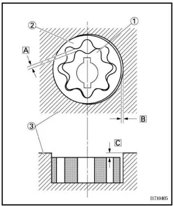
text_image
① ② A B ③ C 117104052. Measure:
- Tip clearance A
(between the inner rotor ① and the outer rotor ②) - Side clearance B
(between the outer rotor ② and the oil pump housing ③)
Out of specification → Replace the oil pump assembly.
• Housing and rotor clearance ☐
(between the pump housing ③ and the rotors ① ②)
Out of specification → Replace the oil pump assembly.

Tip clearance A:
0.15 mm (0.0059 in)
Side clearance B:
0.06 \~ 0.10 mm
(0.0024 \~ 0.0039 in)
Housing and rotor clearance ☐:
0.06 \~ 0.10 mm
(0.0024 \~ 0.0039 in)
natural_image
Simple concentric circle diagram with a central hole, no text or symbols presentRotary filter
1. Inspect:
- Rotary filter
Cracks/damage → Replace.
INSPECTION
Pompe à huile
1. Examiner:
natural_image
Simple line drawing of a square frame with a grid pattern on the front face (no text or symbols)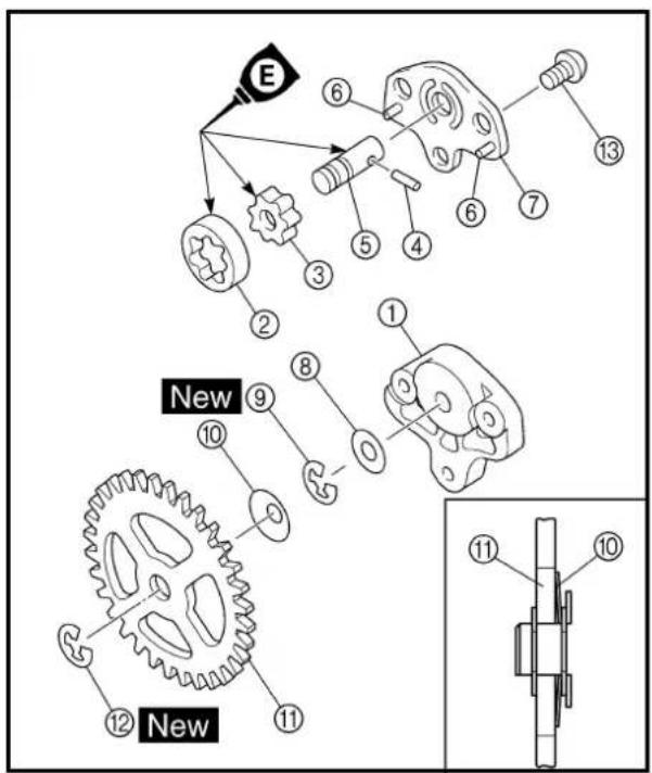
text_image
E New New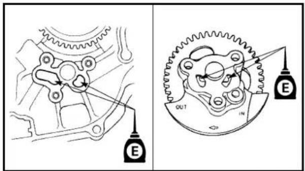
text_image
Technical diagram showing gear meshing and pulley mechanism with labeled components E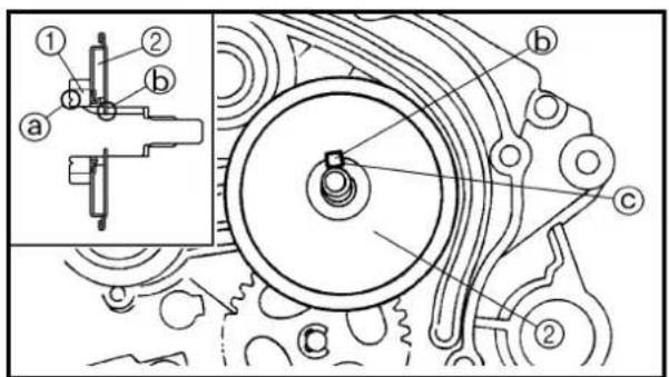
text_image
Technical diagram of a mechanical assembly with labeled parts and an inset view showing a close-up of a gear mechanism.Oil strainer
1. Inspect:
- Oil strainer Cracks/damage → Replace.
Contamination → Clean the flushing oil.
ASSEMBLY AND INSTALLATION
Oil pump
1. Install:
. Oil pump housing ①
. Outer rotor ②
• Inner rotor ③
• Pin ④
. Oil pump shaft ⑤
• Pin ⑥
. Oil pump cover ⑦
.Washer ⑧
• Circlip ⑨ New
. Conical spring washer ⑩
. Oil pump driven gear ⑪
• Circlip ⑫ New
• Screws ⑬
5 Nm (0.5 m · kg, 3.6 ft · lb)
NOTE:
- Apply engine oil onto the outer rotor, inner rotor and oil pump shaft.
• Install the conical spring washer in the direction as shown.
2. Install:
. Oil strainer
. Gasket New
. Oil pump assembly
- Screws (oil pump assembly)
7 Nm (0.7 m · kg, 5.1 ft · lb)
NOTE:
Apply engine oil onto the crankcase oil passage and oil pump assembly.
3. Install:
- Oil pump drive gear ①
• Rotary filter ②
NOTE:
• Install the oil pump drive gear with its groove @ facing the engine.
• Install the rotary filter with the dog ⑥ facing out.
- Align the rotary filter dog ⓑ with groove © of the crankshaft.
Crépine à huile
1. Examiner:
- Crépine à huile
Crasses/obstructions → Nettoyer.
Ölpumpensieb
1. Kontrollieren:
KICK AXLE AND SHIFT SHAFT
KICK AXLE AND SHIFT SHAFT

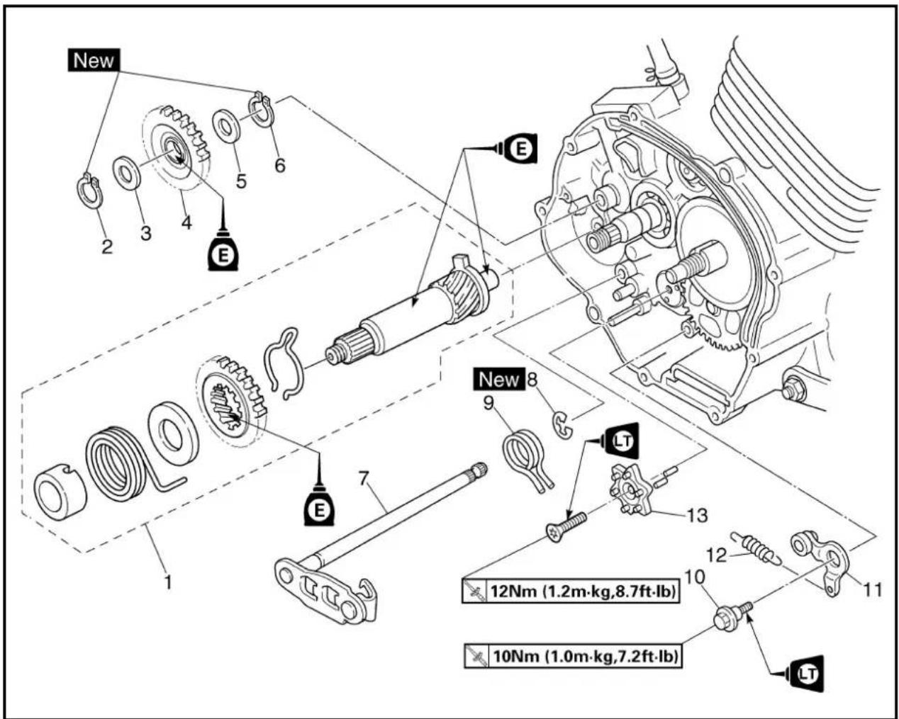
text_image
New 2 3 4 5 6 E 1 7 E New 8 9 LT 13 12Nm (1.2m·kg,8.7ft·lb) 10Nm (1.0m·kg,7.2ft·lb) LTExtent of removal: ① Kick axle removal ② Shift shaft removal
| Extent of removal Order Part name Q'ty Remarks | ||||
| Preparation for removal Shift pedal link Refer to “ENGINE REMOVAL” section. | ||||
| Clutch Refer to “CLUTCH AND PRIMARYDRIVEN GEAR” section. | ||||
| Special | Special | 1 Kick axle assembly 1 Refer to “REMOVAL POINTS”. | ||
| 2 Circlip 13 Washer 14 Kick idle gear 15 Washer 16 Circlip 17 Shift shaft 18 Circlip 19 Torsion spring 110 Bolt (stopper lever)11 Stopper lever12 Spring13 Segment | 11111Refer to “REMOVAL POINTS”. | |||
AXE DE KICK ET ARBRE DE SÉLECTEUR
AXE DE KICK ET ARBRE DE SÉLECTEUR
text_image
Technical diagram of mechanical assembly with labeled parts ① and ②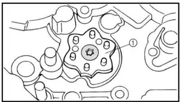
text_image
Technical diagram of a mechanical component with numbered parts and a star-shaped feature labeled '①'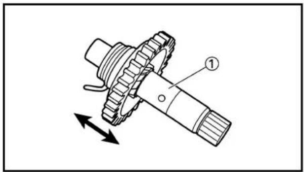
text_image
Technical diagram of a gear and shaft assembly with labeled component ①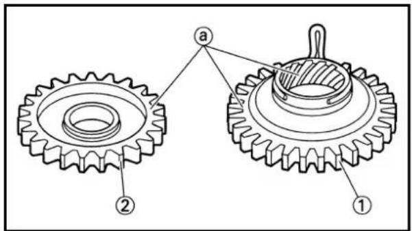
text_image
Technical diagram of two gear components with labeled parts, showing gear structure and assembly details.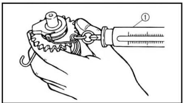
natural_image
Illustration of a hand holding a mechanical device with a spring and chain, no text or symbols presentREMOVAL POINTS
Kick axle
- Remove:
• Kick axle assembly ①
NOTE:
Unhook the torsion spring ② from the hole in the crankcase.
Segment
- Remove:
• Screw (segment)
• Segment ①
NOTE:
Loosen the screw using the T30 bit.
INSPECTION
Kick axle and kickstarter segment gear
- Check:
- Kickstarter segment gear smooth movement Unsmooth movement → Replace.
- Inspect:
- Kick axle ① Wear/damage → Replace.
Kickstarter segment gear and kick idle gear
- Inspect:
• Kickstarter segment gear ①
• Kick idle gear ②
- Gear teeth @ Wear/damage → Replace.
Kick axle clip
- Measure:
- Kick axle clip friction force (torsion spring) Out of specification → Replace. Use a spring gauge ①.
Kick axle clip friction force: 0.65 \~ 1.35 kg (1.4 \~ 3.0 lb)
text_image
Technical diagram of a mechanical lever with labeled parts ① and ②
text_image
Technical diagram of a mechanical clamp or bracket with labeled parts ① and ②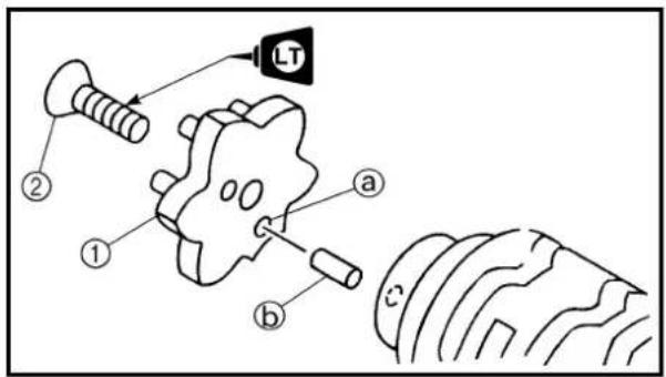
text_image
LT ② ① a b c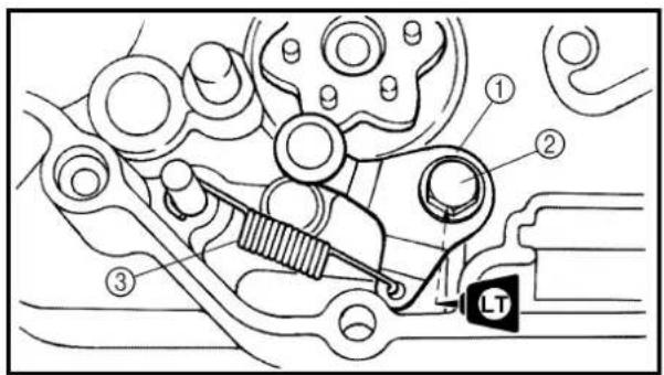
text_image
Technical diagram of a mechanical assembly with numbered components and a labeled component 'LT'EC4B4400
Shift shaft
1. Inspect:
- Shift shaft ① Bend/damage → Replace.
- Spring ② Broken → Replace.
EC4B4500
Stopper lever
1. Inspect:
- Stopper lever ①
Wear/damage → Replace.
• Torsion spring ② Broken → Replace.
EC4C5000
ASSEMBLY AND INSTALLATION
Segment
1. Install:
- Segment ① - Screw (segment) ②
12 Nm (1.2 m · kg, 8.7 ft · lb)
NOTE:
- Align the notch ⓐ on the segment with the pin ⓑ on the shift cam.
• Tighten the screw using the T30 bit.
Stopper lever
1. Install:
10 Nm (1.0 m · kg, 7.2 ft · lb)
- Stopper lever ①
- Bolt (stopper lever) ②
• Torsion spring ③
NOTE:
Align the stopper lever roller with the slot on segment.
text_image
Technical diagram of a mechanical assembly with numbered components and labeled parts, including a 'LS' indicator.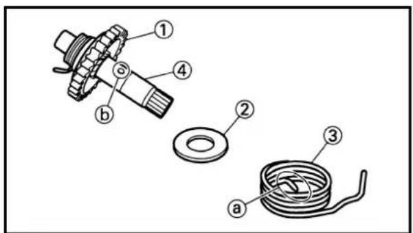
text_image
Technical diagram of mechanical assembly with numbered parts labeled 1 through 4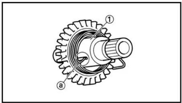
text_image
Technical diagram of a gear assembly with labeled parts ① and ②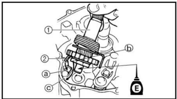
text_image
Technical diagram of a mechanical assembly with labeled parts and a labeled component E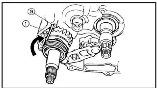
text_image
Technical diagram of a mechanical assembly with labeled parts and directional arrow indicating rotation or movement.Shift shaft
- Install:
- Shift shaft ①
NOTE:
- Apply the lithium soap base grease on the oil seal lips.
- Hook the spring ends onto the stopper ②.
Kick axle assembly
- Install:
• Kickstarter segment gear ①
- Plain washer ②
• Torsion spring ③
On kick axle ④.
NOTE:
Make sure the stopper ⓐ of the torsion spring fits into the hole Ⓑ on the kick axle.
- Install:
• Spring guide ①
NOTE:
Slide the spring guide into the kick axle, make sure the groove @ in the spring guide fits on the stopper of the torsion spring.
- Install:
• Kick axle assembly ①
NOTE:
- Apply the engine oil on the kick axle.
-
Slide the kick axle assembly into the crank-case, make sure the clip ② and kick axle stopper ⑥ fit into their home positions ④, ⑤.
-
Hook:
• Torsion spring ①
NOTE:
Turn the torsion spring clockwise and hook into the proper hole ⓐ in the crankcase.
text_image
New ⑤ ④ ③ ② ① New EKick idle gear
- Install:
• Circlip ①
New
.Washer ②
• Kick idle gear ③
.Washer ④
• Circlip ⑤
New
NOTE:
- Apply the engine oil on the kick idle gear inner circumference.
• Install the kick idle gear with its depressed side toward you.
Extent of removal: ① CDI magneto removal
| Extent of removal Order Part name Q'ty Remarks | ||||
| Preparation for removal | Seat and | CDI MAGNETO REMOVALfuel tank Refer to “SAET, FUEL TANK AND SIDECOVERS” section.Drain the engine oil Refer to “ENGINE OILREPLACEMENT”section in the CHAPTER 3.Drive sprocket cover Refer to “ENGINE REMOVAL” section. | ||
| 1 | 1 CDI magneto lead 12 Left crankcase cover 13 Nut (rotor) 14 Rotor 15 Woodruff key 16 Pickup coil 17 Lead guide8 Stator | 1 | Use special tool.Refer to “REMOVAL POINTS”. | |
MAGNÉTO CDI

text_image
Technical diagram of a mechanical assembly with numbered components, likely a pump or motor component.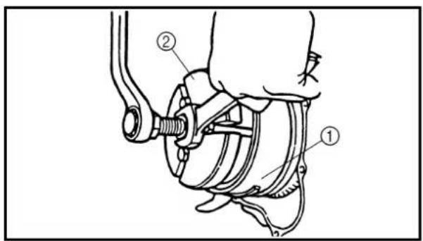
text_image
Technical diagram of a mechanical assembly with labeled parts ① and ②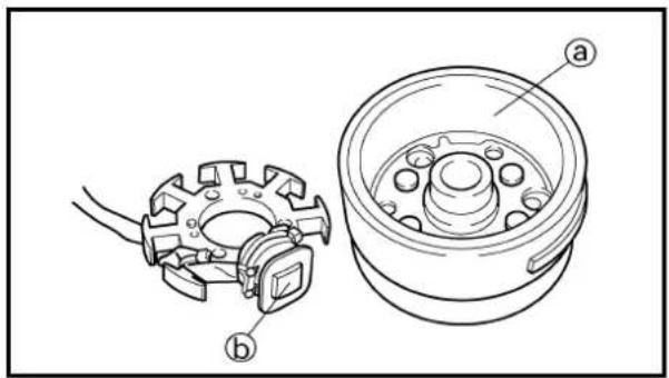
natural_image
Technical line drawing of a mechanical assembly with two views: one showing a gear-like component and the other showing a circular housing (no text or symbols)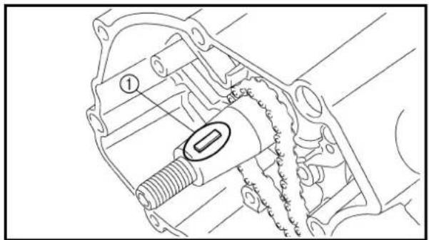
natural_image
Technical line drawing of a mechanical assembly with no visible text or symbols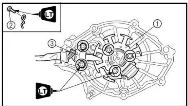
text_image
Technical diagram of a mechanical assembly with labeled parts and an inset showing a component labeled 'LT'.REMOVAL POINTS
Rotor
- Remove:
• Nut (rotor) ①
- Plain washer ②
Use the sheave holder ③.

Sheave holder: YS-1880-A/90890-01701
- Remove:
• Rotor ①
Use the flywheel puller ②.

Flywheel puller: YU-33270-B/90890-01362
EC4L4000
INSPECTION
EC4L4101
CDI magneto
-
Inspect:
-
Rotor inner surface ⓐ
• Stator outer surface ⓑ
Damage → Inspect the crankshaft runout and crankshaft bearing.
If necessary, replace CDI magneto and/or stator.
EC4L4200
Woodruff key
- Inspect:
• Woodruff key ①
Damage → Replace.
EC4L5000
ASSEMBLY AND INSTALLATION
CDI magneto
- Install:
• Stator ①
• Bolt (stator)
10 Nm (1.0 m · kg, 7.2 ft · lb)
- Lead guide
• Screw (lead guide) ②
7 Nm (0.7 m · kg, 5.1 ft · lb)
• Pickup coil ③
• Bolt (pickup coil)
10 Nm (1.0 m · kg, 7.2 ft · lb)
PIÈCES À DÉPOSER
Rotor
-
Déposer:
-
Écrou (rotor) ①
• Rondelle plate ②
text_image
Technical diagram of a mechanical assembly with labeled parts, including piston, crankshaft, and housing components.2. Install:
• Woodruff key ①
• Rotor ②
NOTE:
- Clean the tapered portions of the crankshaft and rotor.
- When installing the woodruff key, make sure that its flat surface ⓐ is in parallel with the crankshaft center line ⓑ.
- When installing the rotor, align the keyway of the rotor with the woodruff key.
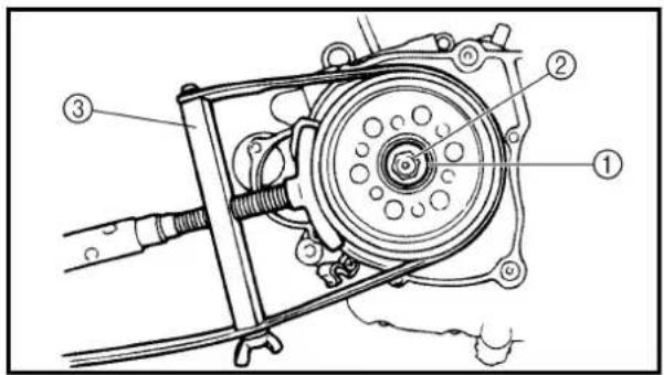
text_image
Technical diagram of a mechanical assembly with numbered components labeled 1, 2, and 33. Install:
- Plain washer ①
• Nut (rotor) ②
80 Nm (8.0 m · kg, 58 ft · lb)
Use the sheave holder ③.

Sheave holder: YS-1880-A/90890-01701
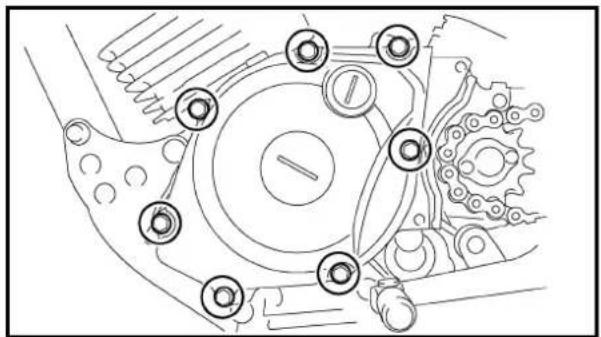
natural_image
Technical line drawing of a mechanical gear assembly with no visible text or symbols4. Install:
• Dowel pin
• Gasket New
• Left crankcase cover
• Bolt (left crankcase cover)
10 Nm (1.0 m · kg, 7.2 ft · lb
NOTE:
Tighten the screws in stage, using a crisscross pattern.
5. Connect:
• CDI magneto lead
Refer to "CABLE ROUTING DIAGRAM" section in the CHAPTER 2.
MAGNÉTO CDI LICHTMASCHINENROTOR
ENG

2. Installer:
Extent of removal:
① Engine removal
| Extent of removal Order Part name Q'ty Remarks | ||||
| Preparation for removal | Hold the | ENGINE REMOVALmachine by placing the suitable stand under the frame.Seat, fuel tank and side covers Refer to “SECarburetor Refer to “CARBURETOR” section.Muffler Refer to “MUFFLER” section.Clutch cable Disconnect at engine side.Spark plug capDisconnect the CDI magneto lead.Drain the engine oil. Refer to “ENGINE OIL | SEAT, FUEL TANK AND SIDE COVERS” section.REPLACEMENT”section in the CHAPTER 3. | |
DÉPOSE DU MOTEUR
| Extent of removal Order Part name Q'ty Remarks | |||
| 1 | 1 Drive sprocket cover 12 Bolt (drive sprocket) 24 Drive sprocket 15 Shift pedal link 16 Crankcase breather hose 17 Engine bracket (upper) 18 Engine skidplate 19 Engine bracket (front) 110 Engine mounting bolt (rear)Engine | 21 | Refer to “REMOVAL POINTS”.3 Drive sprocket holder 1Refer to “REMOVAL POINTS”. |
natural_image
Technical line drawing of a mechanical gear assembly with no visible text or symbols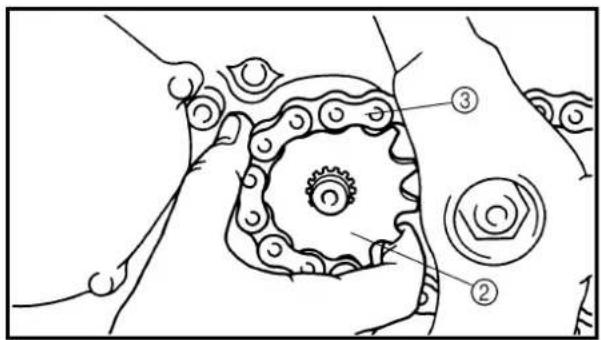
text_image
Technical diagram showing mechanical components with numbered labels ② and ③ indicating parts of a gear or chain assembly.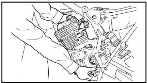
natural_image
Technical line drawing of a mechanical assembly with hands and components (no text or symbols)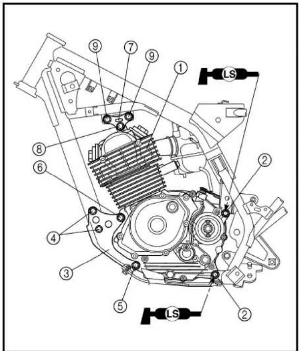
text_image
Technical diagram of a mechanical assembly with numbered components and labeled parts (LS)REMOVAL POINTS
Drive sprocket
1. Remove:
- Bolt (drive sprocket)
- Drive sprocket holder ①
- Drive sprocket ②
- Drive chain ③
NOTE:
Remove the drive sprocket together with the drive chain.
Engine removal
1. Remove:
- Engine ①
From left side.
NOTE:
Make sure that the couplers, hoses and cables are disconnected.
ASSEMBLY AND INSTALLATION
Engine installation
1. Install:
- Engine ① Install the engine from left side.
• Engine mounting bolt (rear) ②
• Engine bracket (front) ③
• Bolt (engine bracket) ④
• Engine mounting bolt (lower) ⑤
• Engine mounting bolt (front) ⑥
• Engine mounting bolt (upper) ⑧
- Apply the lithium soap base grease on the thread of the engine mounting bolts (rear) ②.
- Tighten the engine mounting bolt (upper) ⑧, and then tighten the bolts (engine bracket) ⑨.
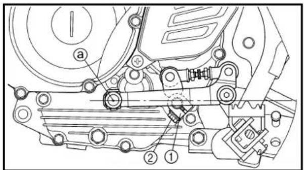
text_image
Technical diagram of a mechanical assembly with numbered components and labeled parts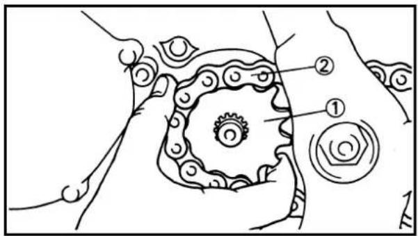
text_image
Diagram of a mechanical or electrical component with labeled parts ① and ②, showing gear-like structure and connections.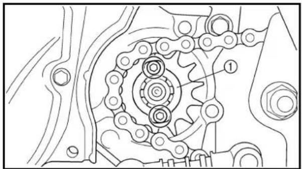
natural_image
Technical line drawing of a mechanical gear assembly with no visible text or symbols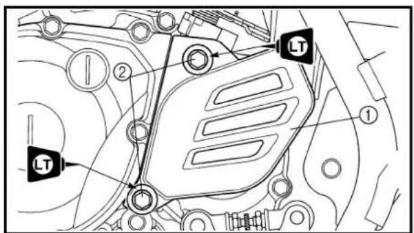
text_image
Technical diagram of a vehicle engine compartment with labeled components and directional arrows indicating flow or movement.Shift pedal link
1. Install:
- Shift pedal link ①
• Bolt (shift pedal link) ②
10 Nm (1.0 m · kg, 7.2 ft · lb)
NOTE:
Adjust the center ⓐ of the front end of the shift pedal to match the highest point of the foot-rest.
Drive sprocket
1. Install:
• Drive sprocket ①
- Drive chain ②
NOTE:
Install the drive sprocket together with the drive chain.
2. Install:
• Drive sprocket holder ①
• Bolt (drive sprocket)
6 Nm (0.6 m · kg, 4.3 ft · lb)
3. Install:
- Drive sprocket cover ①
• Bolt (drive sprocket cover) ②
12 Nm (1.2 m · kg, 8.7 ft · lb)
N.B.:
Extent of removal: ① Crankcase separation ② Balancer removal
③ Crankshaft removal
| Extent of removal Order Part name Q'ty Remarks | ||||
| Preparation for removal | Engine P | CRANKCASE, CRANKSHAFT AND BALANCER REMOVALRefer to “ENGINE REMOVAL” section.Piston Refer to “CYLINDER AND PISTON” Primary drive gear Refer to “CLUTCH AND PRIMARY DRIVEN GEAR” section.Kick axle assembly SegmentRotor and stator Refer to “CDI MAGNETO” | “CLUTCH AND PRIMARY DRIVEN GEAR” section.Refer to “KICK AXLE AND SHIFT SHAFT” section.section. | |
CARTER-MOTEUR, VILEBREQUIN ET BALANCIER KURBELGEHÄUSE, KURBELWELLE UND AUSGLEICHSWELLE
ENG

CARTER-MOTEUR, VILEBREQUIN ET BALANCIER
| Extent of removal Order Part name Q'ty Remarks | |||
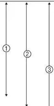 ↓ ↓ | 1 Intake timing chain guide 12 Timing chain 13 Bolt [45 mm (1.8 in)] 74 Bolt [55 mm (2.2 in)] 15 Bolt [30 mm (1.2 in)] 26 Lead guide 17 Clutch cable holder 18 Right crankcase 19 Left crankcase 110 Balancer 111 Crankshaft 1 Use special tool.12 Bearing 3 Refer to “REMOVAL POINTS”. | Use special tool.Refer to “REMOVAL POINTS”.Refer to “REMOVAL POINTS”. | |
text_image
Technical diagram of a mechanical gear assembly with numbered components and eye symbols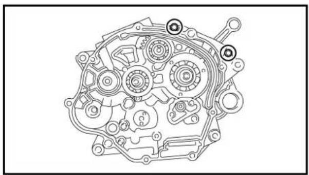
natural_image
Technical line drawing of a mechanical assembly with gears and springs (no text or labels)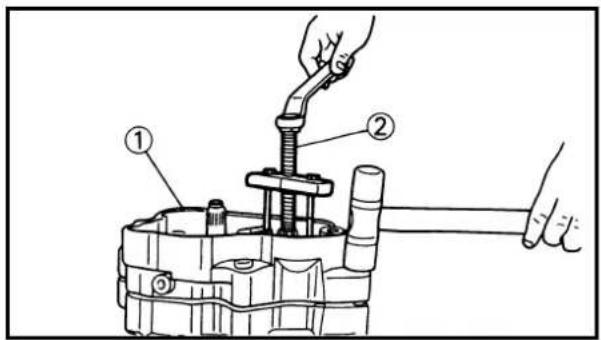
text_image
Technical diagram showing a mechanical assembly with labeled parts, including a tool and a hand holding a shaft.REMOVAL POINTS
Crankcase
- Remove:
• Bolt (crankcase)
- Lead guide ①
- Clutch cable holder ②
NOTE:
Loosen each bolt 1/4 of a turn at a time and after all the bolts are loosened, remove them.
- Remove:
• Right crankcase ①
Use the crankcase separating tool ②.

Crankcase separating tool: YU-1135-A/90890-01135
NOTE:
- Fully tighten the tool holding bolts, but make sure the tool body is parallel with the case. If necessary, one screw may be backed out slightly to level tool body.
- As pressure is applied, alternately tap on the front engine mounting boss and transmission shafts.
CAUTION:
Use soft hammer to tap on the case half. Tap only on reinforced portions of case. Do not tap on gasket mating surface. Work slowly and carefully. Make sure the case halves separate evenly. If one end "hangs up", take pressure off the push screw, realign, and start over. If the cases do not separate, check for a remaining case screw or fitting. Do not force.
CARTER-MOTEUR, VILEBREQUIN ET BALANCIER KURBELGEHÄUSE, KURBELWELLE UND AUSGLEICHSWELLE
ENG

PIÈCES À DÉPOSER
Carter-moteur
1. Déposer:
text_image
Technical diagram of a mechanical assembly with labeled parts ① and ②Crankshaft
- Remove:
• Crankshaft ①
Use the crankcase separating tool ②.

Crankcase separating tool:
YU-1135-A/90890-01135
CAUTION:
Do not use a hammer to drive out the crankshaft.
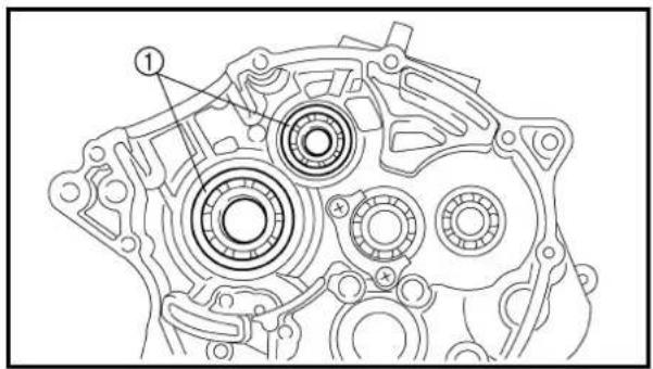
text_image
Technical diagram of an automotive gear assembly with labeled components and numbered calloutsBearing
- Remove:
• Bearing ①
NOTE:
- Remove the bearing from the crankcase by pressing its inner race as shown in.
• Do not use the removed bearing.
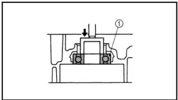
text_image
Technical diagram of a mechanical assembly with labeled component ①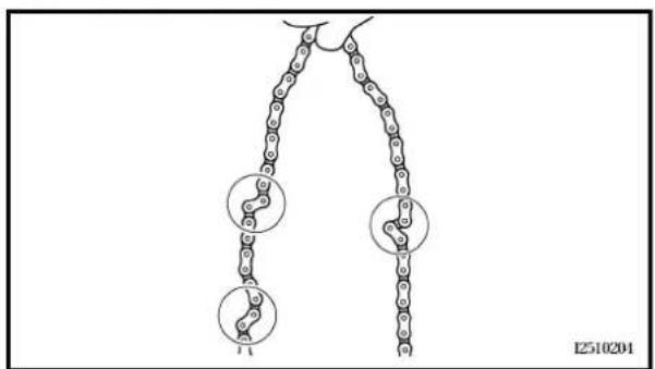
chemical
Diagram of a chain structure with three circular insets showing molecular interactions or structural featuresINSPECTION
Timing chain and timing chain guide
- Inspect:
• Timing chain
Cracks/stiff → Replace the timing chain and camshaft sprocket as a set.
- Inspect:
• Timing chain guide
Wear/damage → Replace.
CARTER-MOTEUR, VILEBREQUIN ET BALANCIER KURBELGEHÄUSE, KURBELWELLE UND AUSGLEICHSWELLE
ENG

Vilebrequin
- Déposer:
• Vilebrequin ①
natural_image
Technical line drawings of two mechanical components (a and b) showing internal gears and housing (no text or symbols)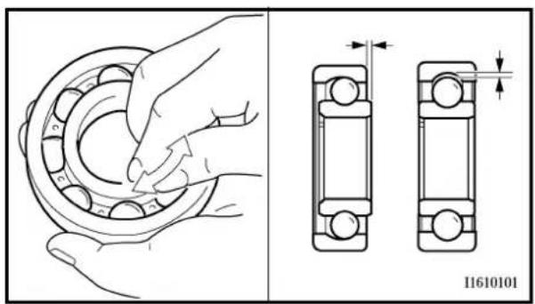
text_image
11610101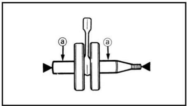
text_image
Diagram of a mechanical device with labeled parts 'a' and directional arrows indicating movement or force.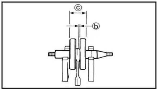
text_image
c bCrankcase
1. Inspect:
- Contacting surface ⓐ
Scratches → Replace.
• Engine mounting boss ⓑ, crankcase
Cracks/damage → Replace.
2. Inspect:
• Bearing
Rotate inner race with a finger.
Rough spot/seizure → Replace.
Crankshaft
1. Measure:
• Runout limit ⓐ
- Connecting rod big end side clearance
⑥
• Crank width ©
Out of specification → Replace.
Use the dial gauge and a thickness gauge.
| Dial gauge & stand set: YU-3097/90890-01252 |
| Standard | ||
| Runout limit: | — | 0.03 mm (0.0012 in) |
| Side clearance: | 0.15 ~ 0.45 mm (0.0059 ~ 0.0177 in) | 0.50 mm (0.02 in) |
| Crack width: | 46.95 ~ 47.00 mm (1.848 ~ 1.850 in) | — |
CARTER-MOTEUR, VILEBREQUIN ET BALANCIER KURBELGEHÄUSE, KURBELWELLE UND AUSGLEICHSWELLE
ENG

Carter-moteur
1. Examiner:
- Plan de joint ⓐ
Rayures → Remplacer.
natural_image
Technical line drawing of a mechanical component with no visible text or symbols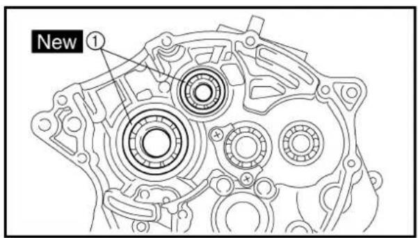
text_image
New ①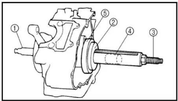
text_image
Technical diagram of a mechanical assembly with numbered components for identification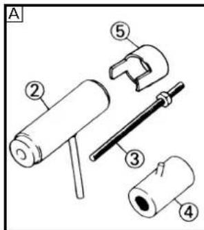
text_image
A ② ③ ④ ⑤
text_image
B ② ③ ④ ⑤Balancer
- Inspect:
• Balancer
Cracks/damage → Replace.
ASSEMBLY AND INSTALLATION
Bearing
- Install:
.Bearing ①
New
On crankcase (left and right).
NOTE:
Install the bearing by pressing its outer race parallel.
Crankshaft
- Install:
• Crankshaft ①
Use the crankshaft installing tool ②, ③, ④, ⑤.
Crankshaft installing tool:
Crankshaft installer pot ②:
YU-90050/90890-01274
Crankshaft installer bolt ③:
YU-90050/90890-01275
Adapter ④:
YU-90063/90890-01278
Spacer ⑤:
YM-91044/90890-04081
A For USA and CDN
B Except for USA and CDN
NOTE:
- Hold the connecting rod at top dead center with one hand while turning the nut of the installing tool with the other. Operate the installing tool until the crankshaft bottoms against the bearing.
- Before installing the crankshaft, clean the contacting surface of crankcase.
CAUTION:
Do not use a hammer to drive in the crankshaft.
CARTER-MOTEUR, VILEBREQUIN ET BALANCIER KURBELGEHÄUSE, KURBELWELLE UND AUSGLEICHSWELLE
ENG

Balancier
- Examiner:
• Balancier
text_image
Technical diagram showing mechanical assembly with labeled parts (a and b) and tool path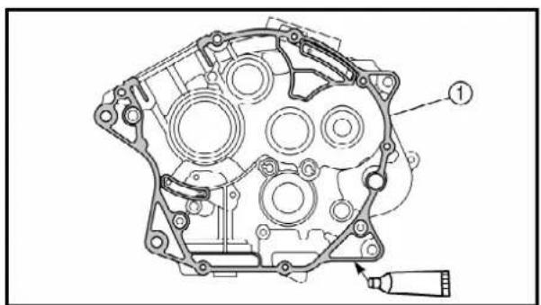
natural_image
Technical line drawing of an internal combustion engine component (no text or labels)2. Install:
- Balancer
NOTE:
Align the punched mark ① on the balancer drive gear with the punched mark ② on the balancer driven gear.
Crankcase
1. Apply:
- Sealant
On the right crankcase ①.

Quick gasket®:
ACC-QUICK-GS-KT
YAMAHA Bond No.1215:
90890-85505
NOTE:
Clean the contacting surface of crankcase (left and right) before applying the sealant.
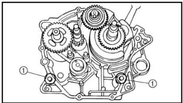
text_image
Technical diagram of a mechanical gear assembly with numbered components2. Install:
. Dowel pin ①
• Right crankcase
On left crankcase.
NOTE:
- Fit the right crankcase onto the left crankcase. Tap lightly on the case with soft hammer.
- When installing the crankcase, the connecting rod should be positioned at TDC (top dead center).
CARTER-MOTEUR, VILEBREQUIN ET BALANCIER KURBELGEHÄUSE, KURBELWELLE UND AUSGLEICHSWELLE
ENG

2. Installer:
- Balancier
N.B.:
text_image
10 mm (0.39 in)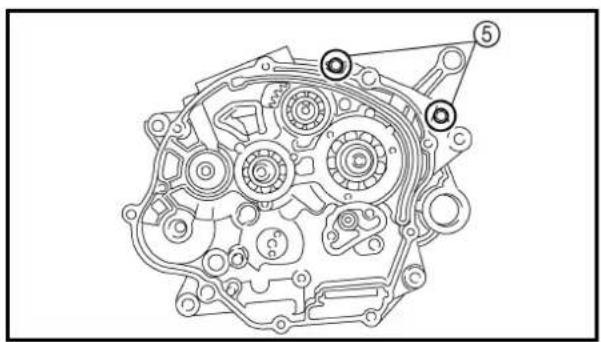
natural_image
Technical line drawing of a mechanical gear assembly (no text or symbols)3. Tighten:
- Lead guide ①
- Clutch cable holder ②
- Bolt (crankcase) [45 mm (1.8 in)] ③
10 Nm (1.0 m · kg, 7.2 ft · lb)
- Bolt (crankcase) [55 mm (2.2 in)] ④
10 Nm (1.0 m · kg, 7.2 ft · lb)
- Bolt (crankcase) [30 mm (1.2 in)] ⑤
10 Nm (1.0 m · kg, 7.2 ft · lb)
NOTE:
- Apply Quick gasket® (YAMAHA Bond No.1215) on end of the crankcase bolts [45 mm (1.8 in)] ③, as shown.
- Tighten the crankcase bolts in stage, using a crisscross pattern.

Quick gasket®: ACC-QUICK-GS-KT YAMAHA Bond No.1215: 90890-85505
4. Check:
- Crankshaft and transmission operation Unsmooth operation → Repair.
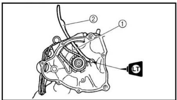
text_image
Technical diagram of a mechanical assembly with labeled parts and a 'LT' tag pointing to a component.5. Install:
- Timing chain ①
- Intake timing chain guide ②
- Bolt (intake timing chain guide)
10 Nm (1.0 m · kg, 7.2 ft · lb)
CARTER-MOTEUR, VILEBREQUIN ET BALANCIER KURBELGEHÄUSE, KURBELWELLE UND AUSGLEICHSWELLE
ENG

3. Serrer:
TRANSMISSION, SHIFT CAM AND SHIFT FORK
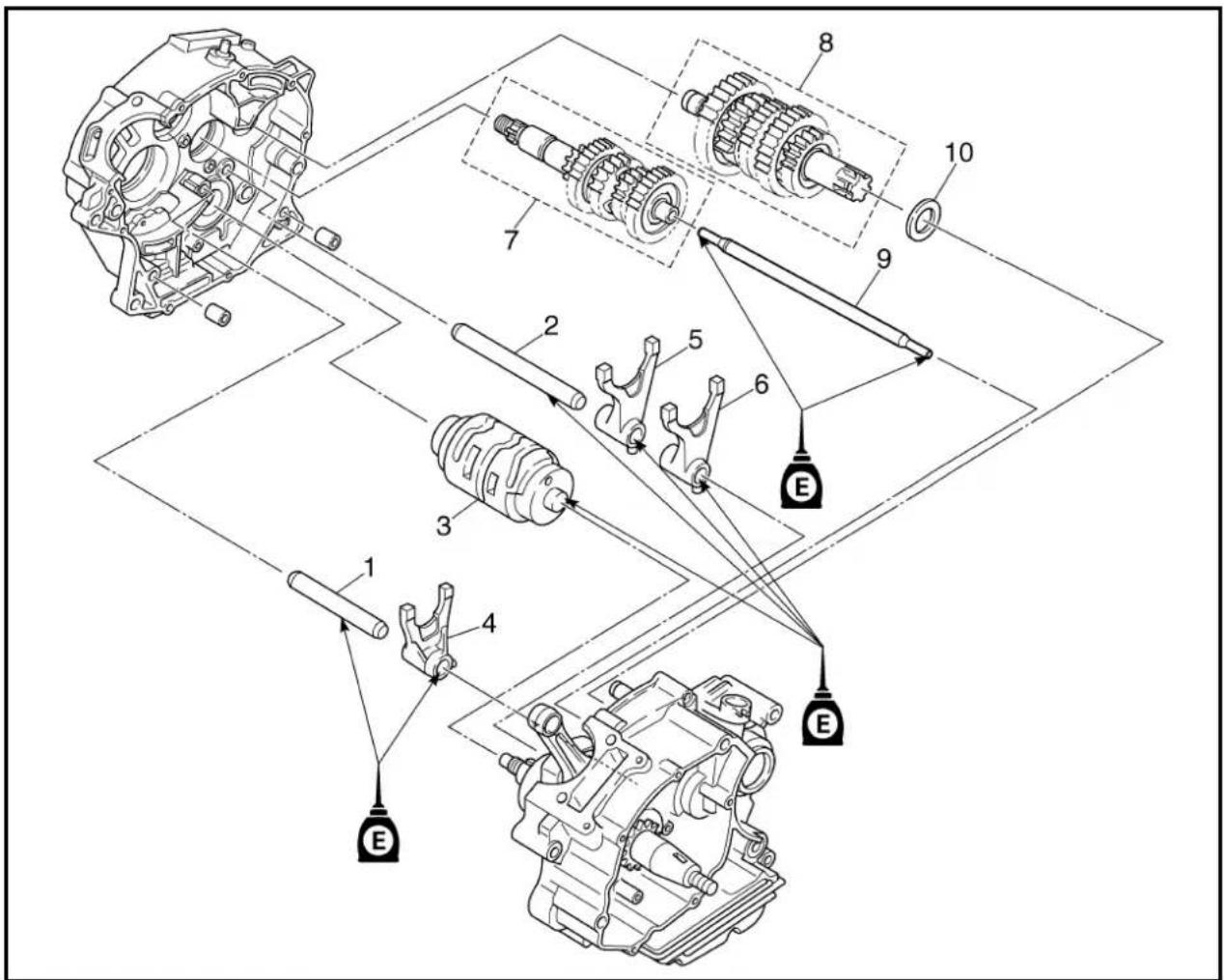
text_image
Technical diagram of a mechanical assembly with numbered components and labeled parts (E)Extent of removal:
① Shift cam and shift fork removal
② Main axle and drive axle removal
| Extent of removal Order Part name Q'ty Remarks | ||||
| Preparation for removal Engine Refer to “ENGINE REMOVAL” section.Separate the crankcase. Refer to “CRANKCASE, CRANKSHAFT AND BALANCER” section. | ||||
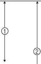 ↓ ↓ | 1 Shift fork guide bar 1 (short) 12 Shift fork guide bar 2 (long) 13 Shift cam 14 Shift fork 2 (C) 15 Shift fork 3 (R) 16 Shift fork 1 (L) 17 Main axle 18 Drive axle 19 Push rod 210 Washer | Refer to “REMOVAL POINTS”. | ||
BOÎTE DE VITESSES, TAMBOUR ET FOURCHETTES DE SÉLECTION
text_image
Technical diagram of a mechanical assembly with numbered components labeled ① and ②REMOVAL POINTS
Transmission
1. Remove:
- Main axle ①
- Drive axle ②
NOTE:
- Tap lightly on the transmission drive axle with a soft hammer to remove.
- Remove assembly carefully. Note the position of each part. Pay particular attention to the location and direction of shift forks.
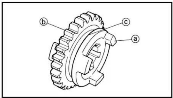
text_image
Technical diagram of a gear with labeled parts a, b, and cEC4H4000
INSPECTION
EC4H4200
Gears
-
Inspect:
-
Matching dog ⓐ
Gear teeth ⑥
• Shift fork groove ©
Wear/damage → Replace.
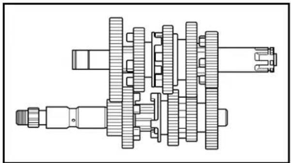
natural_image
Technical line drawing of a mechanical gear assembly (no text or symbols)- Check:
• Gears movement
Unsmooth movement → Repair or replace.
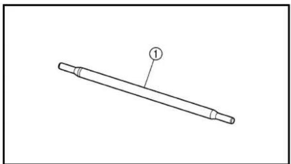
natural_image
Line drawing of a cylindrical mechanical part with a labeled end (1), no text or symbols presentPush rod
- Inspect:
- Push rod 2 ①
Wear/damage/bend → Replace.
PIÈCES À DÉPOSER
Boîte de vitesses
1. Déposer:
text_image
Technical diagram showing mechanical assembly with labeled components and cross-sectional views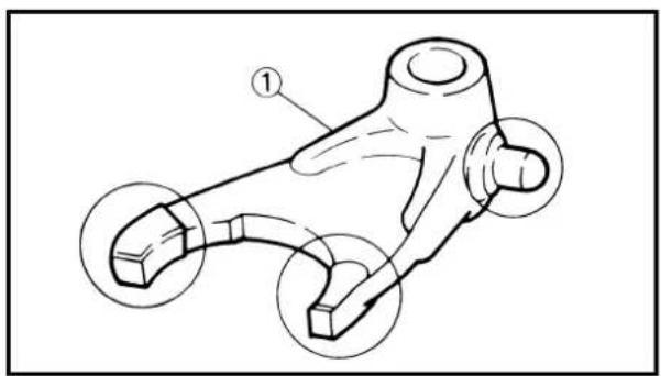
text_image
Technical diagram of a mechanical component with numbered parts and circular annotations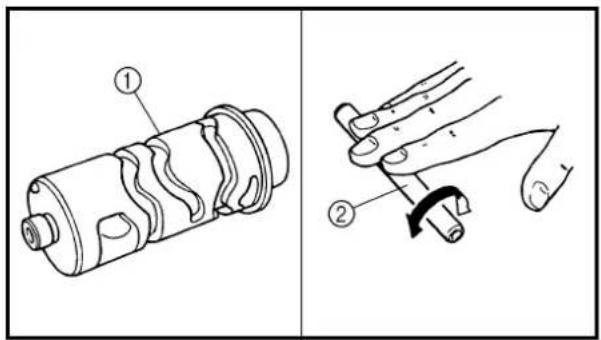
text_image
Technical diagram showing two mechanical assembly steps: one with a cylindrical component and labeled parts, and another with a hand holding a cable.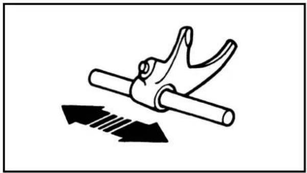
natural_image
Diagram of a hand gripping a cylindrical object with an arrow indicating force or motion (no text or symbols)EC4H4600
Bearing
- Inspect:
- Bearing ① Rotate inner race with a finger. Rough spot/seizure → Replace.
Shift fork and shift cam
- Inspect:
- Shift fork ① Wear/damage/scratches → Replace.
- Inspect:
- Shift cam ① - Shift fork guide bar ② Bend/wear/damage → Replace.
- Check:
- Shift fork movement On its guide bar. Unsmooth operation → Replace shift fork and/or guide bar.
NOTE:
For a malfunctioning shift fork, replace not only the shift fork itself but the two gears each adjacent to the shift fork.
Roulement
1. Examiner:
text_image
Technical diagram of a mechanical assembly with numbered components and a labeled component M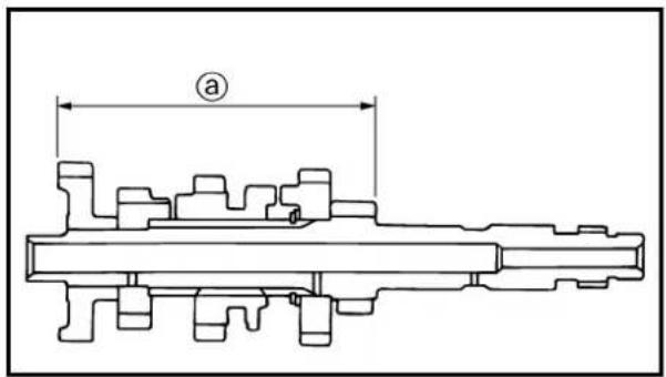
text_image
a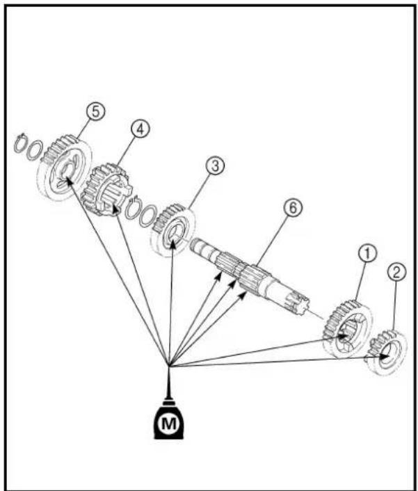
text_image
Technical diagram of a mechanical transmission system with numbered components and a labeled component MTransmission
- Install:
• 4th pinion gear (22T) ①
• 3rd pinion gear (19T) ②
•2nd pinion gear (18T) ③
- 5th pinion gear (24T) ④
On main axle ⑤.
NOTE:
-
Apply the molybdenum disulfide oil on the gears' inner circumference.
• Install the 5th pinion gear so that measurement @ is 83.25 \~ 83.45 mm (3.278 \~ 3.285 in). -
Install:
•2nd wheel gear (32T) ①
• 5th wheel gear (21T) ②
- 3rd wheel gear (25T) ③
• 4th wheel gear (23T) ④
- 1st wheel gear (37T) ⑤
On drive axle ⑥.
NOTE:
Apply the molybdenum disulfide oil on the gears' inner circumference.
Boîte de vitesses
1. Installer:
text_image
New ① ② ③ a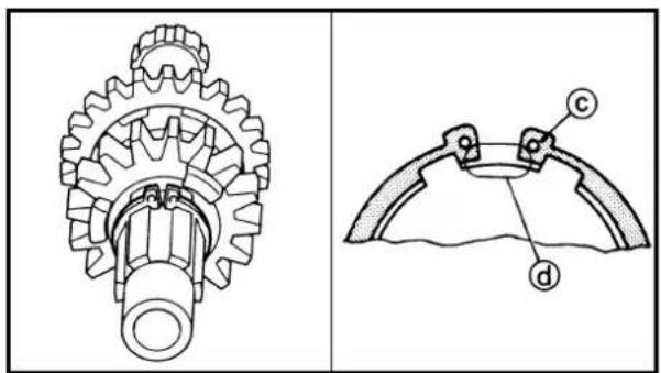
text_image
Technical diagram showing gear and cam mechanism with labeled parts (a, b, c)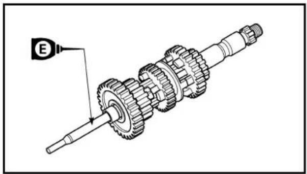
natural_image
Mechanical assembly diagram showing a shaft and gear mechanism with a labeled component (E), no text or symbols present.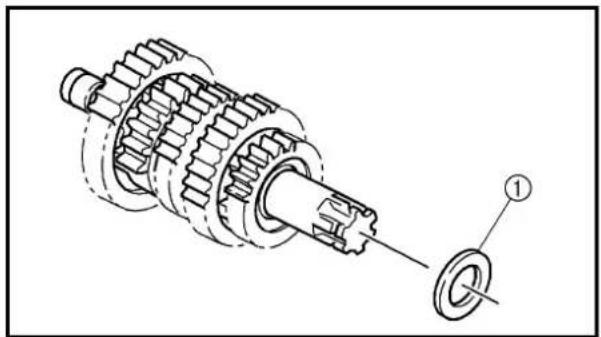
natural_image
Mechanical assembly diagram showing gear and shaft components with a labeled part (1), no text or symbols present.-
Install:
-
Plain washer ①
• Circlip ② New
NOTE:
- Be sure the circlip sharp-edged corner ⓐ is positioned opposite side to the plain washer and gear ⓑ.
-
Be sure the circlip end © is positioned at axle spline groove ⓐ.
-
Install:
- Push rod 2
On main axle.
NOTE:
Apply the engine oil on the push rod 2.
- Install:
.Washer ①
On drive axle.
- Install:
• Main axle
- Drive axle
Install these in the left crankcase at the same time.
NOTE:
- Apply the lithium soap base grease on the oil seal lip.
- When installing the drive axle into the crankcase, pay careful attention to the crankcase oil seal lip.
BOÎTE DE VITESSES, TAMBOUR ET FOURCHETTES DE SÉLECTION GETRIEBE, SCHALTNOCKE UND SCHALTGABEL
ENG

3. Installer:
• Rondelle plate ①
• Circlip ② New
• Circlip ② New
N.B.:
text_image
Technical diagram of a mechanical gear assembly with numbered parts labeled ①, ②, and ③Shift cam and shift fork
-
Install:
-
Shift fork 1 (L) ①
• Shift fork 2 (C) ②
• Shift fork 3 (R) ③
NOTE:
- Mesh the shift fork #1 (L) with the 2nd wheel gear and #3 (R) with the 4th wheel gear on the drive axle.
- Mesh the shift fork #2 (C) with the 3rd pinion gear on the main axle.
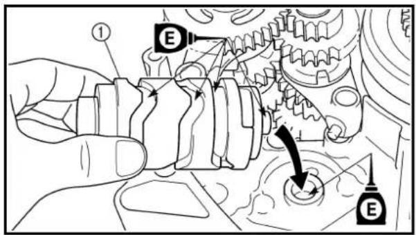
text_image
Technical diagram showing mechanical assembly with labeled components E and numbered parts, likely illustrating gear or mechanical assembly.- Install:
- Shift cam ①
NOTE:
Apply the engine oil on the shift cam.
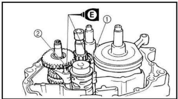
text_image
Technical diagram of a mechanical assembly with labeled parts and a marked component E- Install:
• Shift fork guide bar 1 (short) ①
• Shift fork guide bar 2 (long) ②
NOTE:
- Apply the engine oil on the guide bars.
- Be sure the long bar is inserted into the shift forks #1 and #3 and the short one into #2.
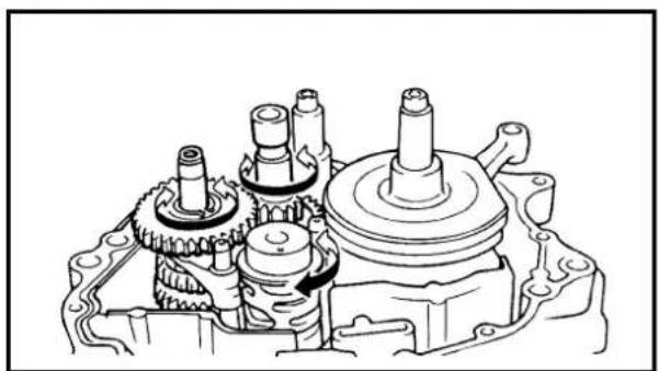
natural_image
Technical line drawing of a mechanical assembly with gears and shafts (no text or symbols)-
Check:
-
Shifter operation
• Transmission operation
Unsmooth operation → Repair.
① Front wheel removal
② Wheel bearing removal
③ Brake shoe plate assembly removal and disassembly
| Extent of removal Order Part name Q'ty Remarks | ||||
| Preparation for removal | FRONT WHEEL AND DRUM BRAKEHold the machine by placing the suitable stand under the engine. | WARNINGSupport the machine securely so there is no danger of it falling over. | ||
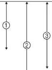 ↓ ↓ | 1 Brake cable holder 12 Brake cable 1 Disconnect at the lever side, first.3 Axle nut 14 Wheel axle 15 Front wheel 16 Collar set 17 Brake shoe plate assembly 18 Oil seal 19 Wheel bearing 2 Refer to “REMOVAL POINTS”.10 Spacer | |||
PARTIE CYCLE
ROUE AVANT ET FREIN AVANT (TT-R125)
text_image
Technical diagram of a mechanical assembly with labeled parts, showing gear and shaft components.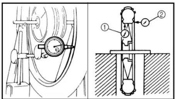
text_image
Technical diagram showing mechanical device and mechanical assembly with labeled components
natural_image
Technical line drawing of two mechanical components with dimension arrows (no text or symbols)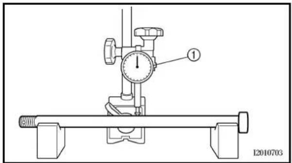
text_image
1 I2010703REMOVAL POINTS
EC513201
Wheel bearing (if necessary)
- Remove:
- Bearing ①
NOTE:
Remove the bearing using a general bearing puller ②.
INSPECTION
EC514100
Wheel
- Measure:
. Wheel runout
Out of limit → Repair/replace.

Wheel runout limit:
Radial ①: 2.0 mm (0.08 in)
Lateral ②: 2.0 mm (0.08 in)
- Inspect:
- Bearing
Rotate inner race with a finger.
Rough spot/seizure → Replace.
NOTE:
Replace the bearings, oil seal and wheel collar as a set.
EC514200
Wheel axle
- Measure:
- Wheel axle bends
Out of specification → Replace.
Use the dial gauge ①.

Wheel axle bending limit:
0.5 mm (0.020 in)
NOTE:
The bending value is shown by one half of the dial gauge reading.

WARNING
Do not attempt to straighten a bent axle.
ROUE AVANT ET FREIN AVANT (TT-R125) VORDERRAD UND VORDERRADBREMSE (TT-R125)

PIÈCES À DÉPOSER
natural_image
Illustration of hands using a tool to clean or fabric the surface, no text or symbols present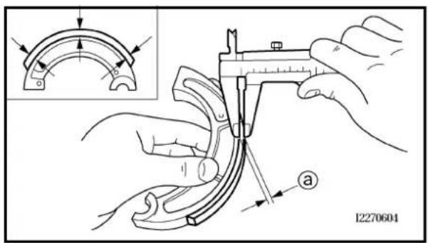
text_image
12270604Drum brake
1. Inspect:
- Brake shoe lining surface Glazed areas → Polish. Use coarse sand paper.
NOTE:
After polishing, wipe the polished particles with a cloth.
2. Measure:
- Brake shoe lining thickness ⓐ Out of specification → Replace.
| Brake shoe lining thickness: | ||
| Standard | ||
| 40 mm(0.16 in) | 2.0 mm(0.08 in) | |
NOTE:
Replace the brake shoes and springs as a set if either is worn to the limit.
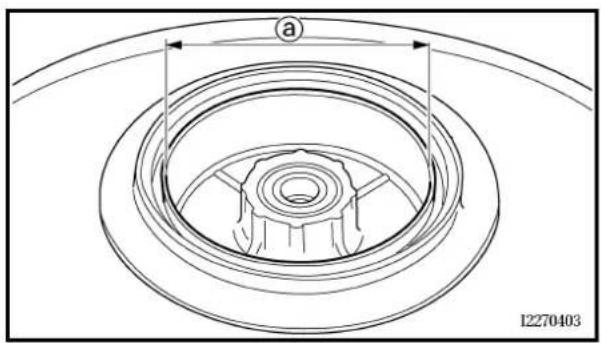
text_image
a 122704033. Measure:
- Brake drum inside diameter ① Out of specification → Replace.
| Brake drum inside diameter: | ||
| Standard | ||
| 110 mm(4.33 in) | 111 mm(4.37 in) | |
4. Inspect:
- Brake drum inner surface Oil/scratches → Remove.
| Oil | Use a rag soaked in lac-quer thinner or a solvent. |
| Scratches | Use a emery cloth (lightly and evenly polishing). |
ROUE AVANT ET FREIN AVANT (TT-R125) VORDERRAD UND VORDERRADBREMSE (TT-R125)

Frein à tambour
1. Examiner:
text_image
Technical diagram showing a mechanical assembly with labeled components and a close-up view of the component.ASSEMBLY AND INSTALLATION
Brake shoe plate assembly
- Install:
- Brake camshaft ①
NOTE:
Apply the lithium soap base grease on the brake camshaft.
- Check:
- Brake camshaft operation
Unsmooth operation → Repair.
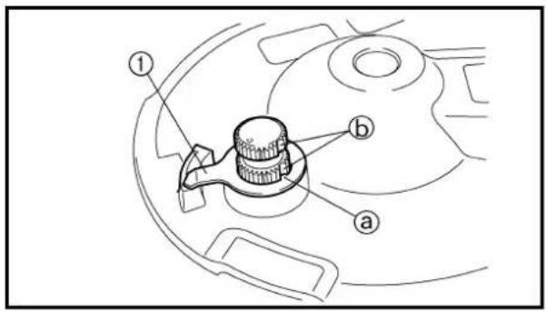
text_image
Technical diagram of a mechanical component with labeled parts a, b, and numbered callouts- Install:
- Wear indicator plate ①
NOTE:
When installing the wear indicator plate to the brake camshaft align the projection ⓐ on the wear indicator plate with the slots Ⓑ on the brake camshaft.
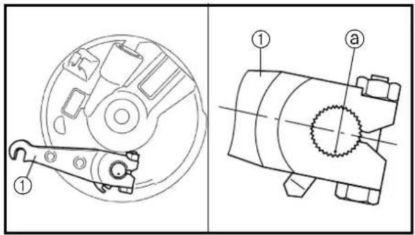
text_image
Technical diagram showing mechanical assembly with labeled parts, including a circular component and a cylindrical device with internal components.- Install:
- Brake camshaft lever ①
10 Nm (1.0 m · kg, 7.2 ft · lb)
NOTE:
Install the brake camshaft lever in relation to the punch mark ⓐ as shown.
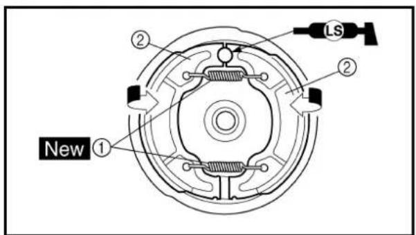
text_image
① ② ② ② New LS- Install:
- Springs ①
New
• Brake shoes ②
NOTE:
Apply the lithium soap base grease on the pivot pin.

WARNING
Do not apply grease to the brake shoe linings.
REMONTAGE ET INSTALLATION
text_image
Technical diagram of a mechanical assembly with labeled parts a and b, showing gear and shaft connections.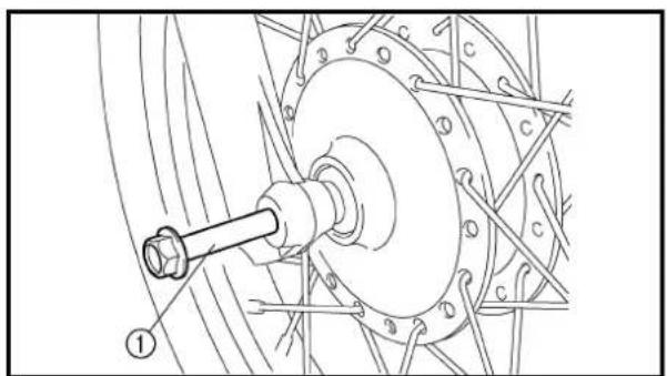
natural_image
Technical line drawing of a mechanical assembly with a central shaft and flanged components (no text or symbols)Front wheel
- Install:
• Wheel bearing ①
• Spacer ②
- Wheel bearing ③
. Oil seal ④ New
NOTE:
- Apply the lithium soap base grease on the wheel bearing and oil seal lip when installing.
• Install the wheel bearing so that the enclosed side is facing outward. - Use a socket that matches the outside diameter of the race of the bearing.
• Left side of wheel bearing shall be installed first.
• Install the oil seal with its manufacture's marks or numbers facing outward.
CAUTION:
Do not strike the inner race of the bearing. Contact should be made only with the outer race.
- Install:
• Brake shoe plate assembly
• Collar set ①
NOTE:
Apply the lithium soap base grease on the oil seal lip.
- Install:
- Front wheel
NOTE:
Make sure that the slot ⓐ on the brake shoe plate with the stopper Ⓑ on the front fork outer tube.
- Install:
- Wheel axle ①
Roue avant
natural_image
Technical line drawing of a mechanical assembly with no visible text or symbols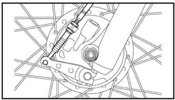
natural_image
Technical line drawing of a mechanical assembly with no visible text or symbols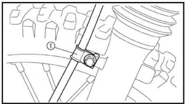
natural_image
Technical line drawing of a mechanical assembly with no visible text or symbols5. Install:
• Axle nut ①
NOTE: ____ Brake camshaft lever side of brake cable shall be installed first.
7. Install:
- Brake cable holder ①
7 Nm (0.7 m · kg, 5.1 ft · lb)
8. Adjust:
- Brake lever free play Refer to "FRONT BRAKE ADJUSTMENT" section in the CHAPTER 3.
ROUE AVANT ET FREIN AVANT (TT-R125) VORDERRAD UND VORDERRADBREMSE (TT-R125)

5. Installer:
- Écrou d'axe ①
45 Nm (4,5 m · kg, 32 ft · lb)
5. Montieren:
• Achsmutter ①
45 Nm (4,5 m · kg)
6. Installer:
• Câble de frein
N.B.:
Extent of removal: ① Front wheel removal ② Wheel bearing removal
③ Brake disc removal
| Extent of removal Order Part name Q'ty Remarks | |||||
| Preparation for removal | FRONT WHEEL REMOVALHold the machine by placing the suitable stand under the engine. | WARNINGSupport the machine securely so there is no danger of it falling over. | |||
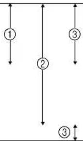 | 1 Axle nut 12 Washer 13 Wheel axle 14 Front wheel 15 Collar 26 Oil seal 27 Wheel bearing 2 Refer to “REMOVAL POINTS”.8 Spacer 19 Brake disk | ||||
ROUE AVANT (TT-R125LW)
text_image
Technical diagram of a mechanical assembly with labeled parts ① and ②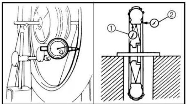
text_image
Technical diagram showing mechanical device and mounting structure with labeled components
natural_image
Technical line drawing of two mechanical components with dimension arrows (no text or symbols)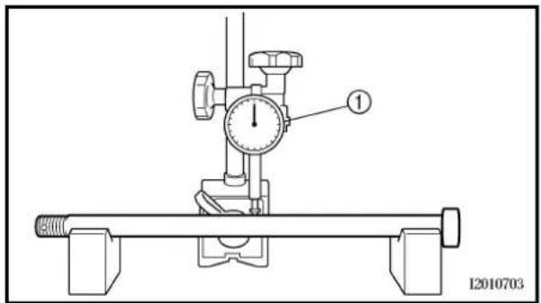
text_image
① I2010703REMOVAL POINTS
EC513201
Wheel bearing (if necessary)
- Remove:
• Bearing ①
NOTE:
Remove the bearing using a general bearing puller ②.
INSPECTION
EC514100
Wheel
- Measure:
- Wheel runout
Out of limit → Repair/replace.

Wheel runout limit:
Radial ①: 2.0 mm (0.08 in)
Lateral ②: 2.0 mm (0.08 in)
- Inspect:
• Bearing
Rotate inner race with a finger.
Rough spot/seizure → Replace.
NOTE:
Replace the bearings, oil seal and wheel collar as a set.
EC514200
Wheel axle
- Measure:
- Wheel axle bends
Out of specification → Replace.
Use the dial gauge ①.

Wheel axle bending limit:
0.5 mm (0.020 in)
NOTE:
The bending value is shown by one half of the dial gauge reading.

WARNING
Do not attempt to straighten a bent axle.
PIÈCES À DÉPOSER
- Brake disc deflection Use the dial gauge ①.
Out of specification → Inspect wheel runout. If wheel runout is in good condition, replace the brake disc.

Disc deflection limit: 0.15 mm (0.006 in)
2. Measure:
- Brake disc thickness ⓐ Out of limit → Replace.
| Disc wear limit: | ||
| Standard | ||
| 3.0 mm(0.12 in) | 2.5 mm(0.10 in) | |
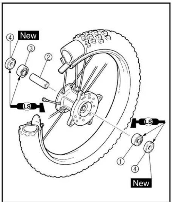
text_image
New ④ ③ ② LS ① ④ New LSASSEMBLY AND INSTALLATION Front wheel
1. Install:
- Wheel bearing ①
- Spacer ②
- Wheel bearing ③
• Oil seal ④
New
NOTE:
- Apply the lithium soap base grease on the wheel bearing and oil seal lip when installing.
• Install the wheel bearing so that the enclosed side is facing outward. - Use a socket that matches the outside diameter of the race of the bearing.
• Left side of wheel bearing shall be installed first.
• Install the oil seal with its manufacture's marks or numbers facing outward.
CAUTION:
Do not strike the inner race of the bearing. Contact should be made only with the outer race.
Disque de frein
1. Mesurer:
text_image
Technical diagram showing a hand operating a mechanical component with labeled parts and a 1:1 indicator.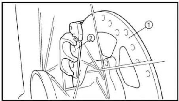
text_image
Technical diagram of a mechanical component with numbered parts labeled ① and ②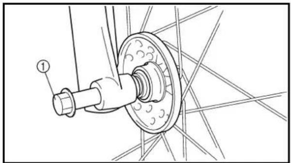
natural_image
Technical line drawing of a mechanical assembly with a bolt and wheel (no text or symbols)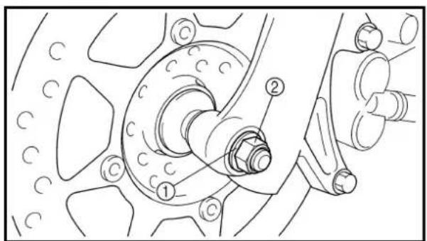
text_image
Technical diagram of a vehicle brake system with labeled components and assembly parts2. Install:
- Brake disc ①
• Bolt (brake disc) ②

12 Nm (1.2 m · kg, 8.7 ft · lb)
NOTE:
Tighten the bolts in stage, using a crisscross pattern.
3. Install:
• Collar ①
NOTE:
- Apply the lithium soap base grease on the oil seal lips.
• Install the longer collar on the brake disc ② side.
4. Install:
- Front wheel
NOTE:
Install the brake disc ① between the brake pads ② correctly.
5. Install:
- Wheel axle ①
6. Install:
- Washer ①
- Axle nut ②
Extent of removal: ① Brake hose removal ② Brake caliper removal
③ Brake master cylinder removal
| Extent of removal Order Part name Q'ty Remarks | ||||
| Preparation for removal | FRONT BRAKE REMOVALHold the machine by placing the suitable stand under the engine.Drain the brake fluid. | WARNINGSupport the machine securely so there is no danger of it falling over.Refer to “REMOVAL POINTS”. | ||
| 1 Brake hose holder 22 Union bolt 13 Brake hose 14 Joint 15 Brake caliper support bolt 16 Brake caliper 1 Refer to “REMOVAL POINTS”.7 Brake lever 18 Brake master cylinder bracket 19 Brake master cylinder | 1 | |||
FREIN AVANT (TT-R125LW)
Extent of removal:
① Brake caliper disassembly
② Brake master cylinder disassembly
| Extent of removal Order Part name Q'ty Remarks | |||
| Preparation for removal | BRAKE CALIPER AND BRAKE MASTER CYLINDER DISASSEMBLYHold the machine by placing the suitable stand under the engine. | ||
| 12 | 1 Brake pad 22 Brake caliper bracket 13 Brake caliper piston 2 Refer to “REMOVAL POINTS”.4 Brake caliper dust seal 25 Brake caliper piston seal 26 Pin boot 17 Sleeve boot 18 Brake master cylinder cap 19 Diaphragm10 Brake master cylinder boot11 Circlip12 Washer13 Brake master cylinder kit | 111111 | |
text_image
Technical diagram of a mechanical device with labeled component ①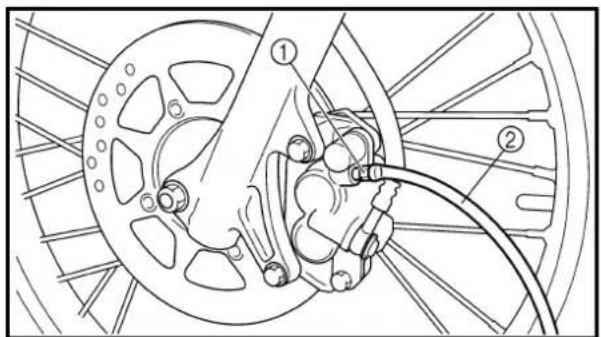
text_image
Technical diagram of a bicycle brake system with labeled components and wiring connections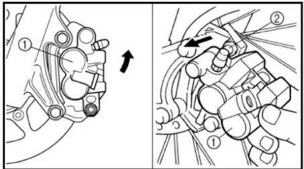
text_image
Technical diagram showing mechanical assembly with numbered components and directional arrow indicating motion or movement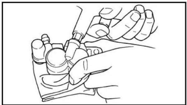
natural_image
Line drawing of a hand holding a small mechanical component (no text or symbols)REMOVAL POINTS
Brake fluid
- Remove:
- Brake master cylinder cap ①
NOTE:
Do not remove the diaphragm.
- Connect the transparent hose ② to the bleed screw ① and place a suitable container under its end.
- Loosen the bleed screw and drain the brake fluid while pulling in the lever.
CAUTION:
. Do not reuse the drained brake fluid.
- Brake fluid may erode painted surfaces or plastic parts. Always clean up spilled fluid immediately.
Brake caliper
- Remove:
- Brake caliper ①
NOTE:
Turn the brake caliper counterclockwise and pull out it from the guide pin ② on the brake caliper bracket.
Brake caliper piston
- Remove:
- Brake caliper piston Use compressed air and proceed carefully.
WARNING
- Cover piston with rag and use extreme caution when expelling piston from cylinder.
. Never attempt to pry out piston.
Brake caliper piston removal steps:
- Insert a piece of rag into the brake caliper to lock one brake caliper.
- Carefully force the piston out of the brake caliper cylinder with compressed air.
PIÈCES À DÉPOSER
Liquide de frein
- Déposer:
text_image
Technical diagram of a mechanical component with labeled parts ① and ②Brake caliper piston seal kit
- Remove:
• Brake caliper dust seal ①
- Brake caliper piston seal ②
NOTE:
Remove the brake caliper piston seals and brake caliper dust seals by pushing them with a finger.
CAUTION:
Never attempt to pry out brake caliper piston seals and brake caliper dust seals.
WARNING
Replace the brake caliper piston seals and brake caliper dust seals whenever a brake caliper is disassembled.
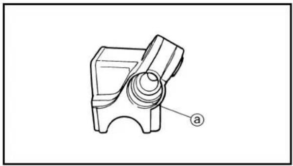
natural_image
Technical line drawing of a mechanical component with a labeled section (a), no readable text or symbols present.INSPECTION
Brake master cylinder
- Inspect:
- Brake master cylinder inner surface @ Wear/scratches → Replace brake master cylinder assembly. Stains → Clean.
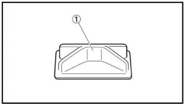
natural_image
Simple line drawing of a rectangular container with internal curved lines and a labeled point (1), no text or symbols present.WARNING
Use only new brake fluid.
- Inspect:
• Diaphragm ① Crack/damage → Replace.
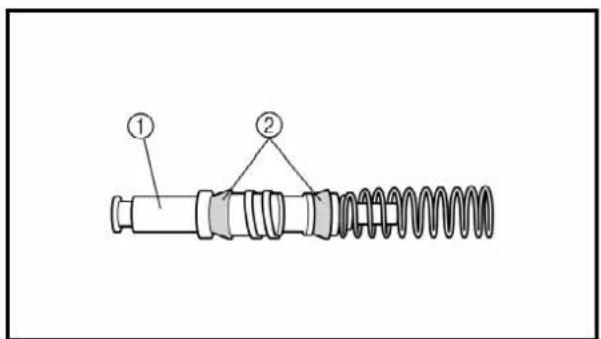
text_image
Technical diagram of a mechanical spring assembly with labeled parts ① and ②- Inspect:
- Brake master cylinder piston ① - Brake master cylinder cup ② Wear/damage/score marks → Replace brake master cylinder kit.
natural_image
Technical line drawing of a mechanical component with threaded and flanged features (no text or symbols)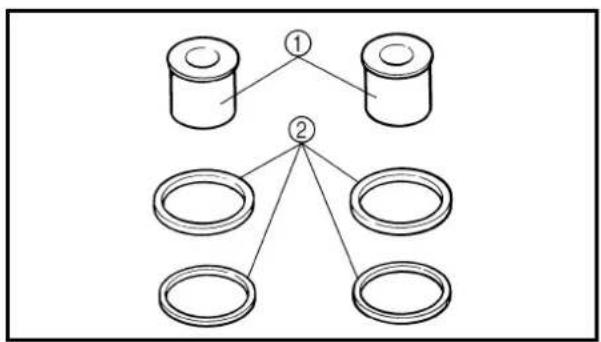
flowchart
graph TD
    A["Component 1"] --> B["Component 2"]
    C["Component 1"] --> B
    D["Component 2"] --> E["Component 3"]
    D --> F["Component 4"]
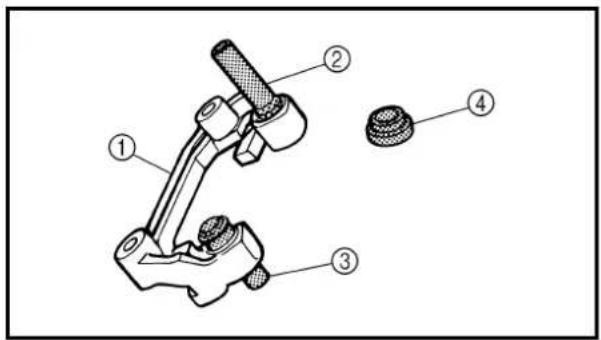
text_image
Technical diagram of a mechanical assembly with numbered components for identification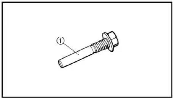
natural_image
Technical line drawing of a bolt with threaded shaft and nut (no text or symbols)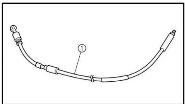
natural_image
Line drawing of a curved mechanical or electrical component with labeled parts (1), no text or symbols present.Brake caliper
1. Inspect:
- Brake caliper cylinder inner surface @ Wear/score marks → Replace brake caliper assembly.
2. Inspect:
- Brake caliper piston ① Wear/score marks → Replace brake caliper piston assembly.
WARNING
Replace the brake caliper piston seals and brake caliper dust seals ② whenever a brake caliper is disassembled.
3. Inspect:
- Brake caliper bracket ① Cracks/damage → Replace the brake caliper assembly. - Guide pin ② Rust/damage → Replace the brake caliper assembly. - Sleeve boot ③ - Pin boot ④ Wear/damage → Replace.
4. Inspect:
- Brake caliper support bolt ① Scorches/rust/damage → Replace.
Brake hose
1. Inspect:
- Brake hose ① Crack/damage → Replace.
Étrier de frein
1. Examiner:
ASSEMBLY AND INSTALLATION
WARNING
- All internal parts should be cleaned in new brake fluid only.
- Internal parts should be lubricated with brake fluid when installed.
- Replace the brake caliper piston seals and brake caliper dust seals whenever a brake caliper is disassembled.
Brake caliper piston
-
Clean:
-
Brake caliper
• Brake caliper piston seal
• Brake caliper dust seal -
Brake caliper piston
Clean them with brake fluid. -
Install:
• Brake caliper piston seal ①
- Brake caliper dust seal ②
New
New
WARNING
Always use new brake caliper piston seals and brake caliper dust seals.
NOTE:
Fit the brake caliper piston seals and brake caliper dust seals onto the slot on brake caliper correctly.
- Install:
- Brake caliper piston ①
NOTE:
Apply the brake fluid on the brake caliper piston wall.
CAUTION:
• Install the brake caliper piston with its shallow depressed side @ facing the brake caliper.
- Never force to insert.
Brake caliper
- Install:
• Sleeve boot ①.
On brake caliper bracket ②.
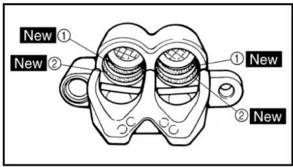
text_image
New ① New ② ① New ② New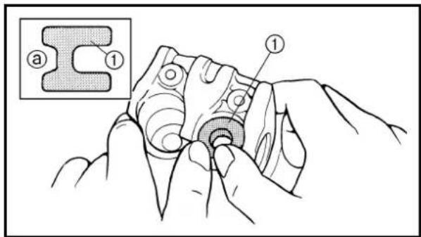
text_image
Technical diagram showing a mechanical assembly with labeled parts (a, 1) and a magnified inset view of a mechanical part.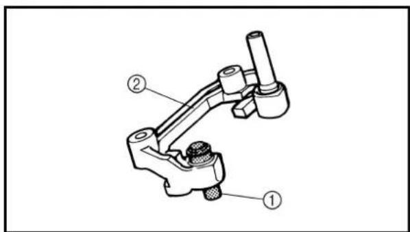
text_image
Technical diagram of a mechanical clamp or bracket assembly with numbered parts labeled ①, ②, and ③.REMONTAGE ET INSTALLATION
AVERTISSEMENT
text_image
Technical diagram of a mechanical component with labeled parts and a labeled connection point 'LS'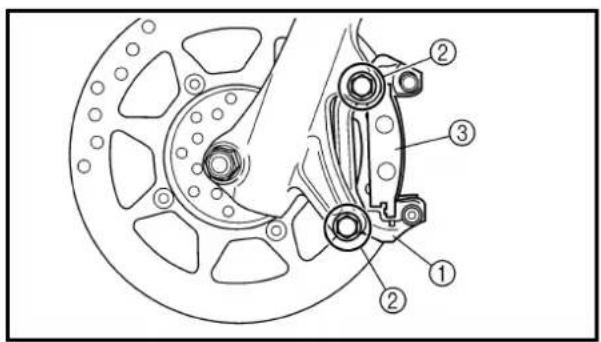
text_image
Technical diagram of a brake caliper assembly with numbered components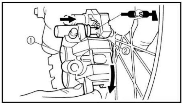
text_image
Technical diagram of a mechanical assembly with labeled parts and directional arrows indicating motion or movement.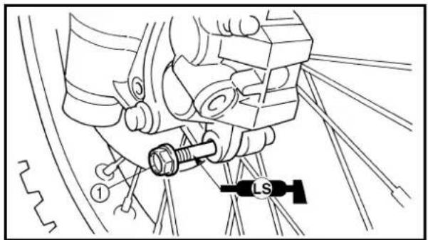
text_image
Technical diagram showing a mechanical assembly with labeled parts and a 'LS' symbol indicating a specific component.2. Install:
• Pin boot ①
On brake caliper ②.
NOTE:
Apply the lithium soap base grease on the pin boot inner surface.
3. Install:
- Brake caliper bracket ①
• Bolt (brake caliper bracket) ②
30 Nm (3.0 m · kg, 22 ft · lb)
• Brake pad ③
4. Install:
- Brake caliper ①
NOTE:
- Apply the lithium soap base grease on the guide pin ②.
• Install the brake caliper into the guide pin and turn it clockwise.
5. Install:
• Brake caliper support bolt ①
22 Nm (2.2 m · kg, 16 ft · lb)
NOTE:
Apply the lithium soap base grease on the brake caliper support bolt.
Brake master cylinder kit
1. Clean:
- Brake master cylinder
- Brake master cylinder kit
Clean them with brake fluid.
FREIN AVANT (TT-R125LW) VORDERRADBREMSE (TT-R125LW)

2. Installer:
text_image
Technical diagram of a mechanical assembly with labeled parts ①, ②, and ③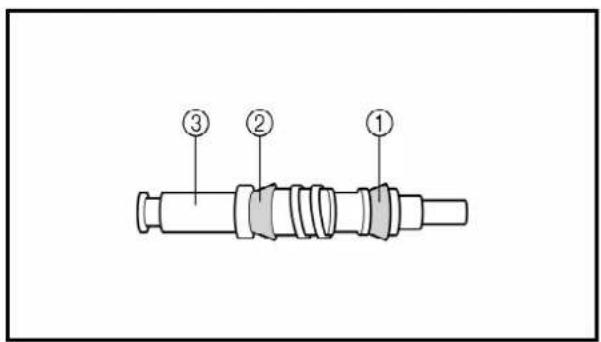
text_image
Diagram of a mechanical component with numbered parts labeled ①, ②, and ③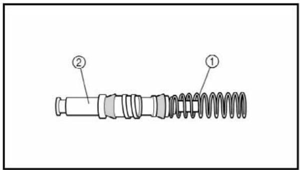
text_image
Technical diagram of a mechanical spring assembly with labeled parts ① and ②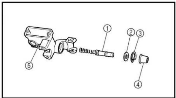
text_image
Technical diagram of a mechanical assembly with numbered parts for identification2. Install:
- Brake master cylinder cup (primary) ①
- Brake master cylinder cup (secondary) ②
On brake master cylinder piston ③.
NOTE:
Apply the brake fluid on the brake master cylinder cup.

WARNING
After installing, cylinder cup should be installed as shown direction. Wrong installation cause improper brake performance.
3. Install:
• Spring ①
On brake master cylinder piston ②.
NOTE:
Install the spring at the smaller diameter side.
4. Install:
• Brake master cylinder kit ①
.Washer ②
• Circlip ③
• Brake master cylinder boot ④
On brake master cylinder ⑤
NOTE:
- Apply the brake fluid on the brake master cylinder kit.
- When installing the circlip, use a long nose circlip pliers.
2. Installer:
text_image
Technical diagram of a mechanical assembly with labeled parts including numbered components and directional indicators.Brake master cylinder
1. Install:
- Brake master cylinder ①
- Brake master cylinder bracket ②
- Bolt (brake master cylinder bracket) ③
9 Nm (0.9 m · kg, 6.5 ft · lb)
NOTE:
• Install the brake master cylinder bracket so that the arrow mark @ face upward.
- First tighten the bolts on the upper side of the brake master cylinder bracket, and then tighten the bolts on the lower side.
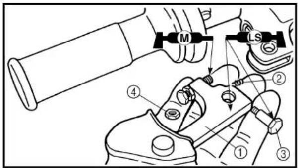
text_image
Technical diagram showing mechanical assembly with labeled parts and directional arrows indicating motion or movement.2. Install:
- Brake lever ①
• Spring ②
• Bolt (brake lever) ③
7 Nm (0.7 m · kg, 5.1 ft · lb) - Nut (brake lever) ④
7 Nm (0.7 m · kg, 5.1 ft · lb)
NOTE:
- Apply the lithium soap base grease on the bolt and brake lever sliding surface.
- Apply the molybdenum disulfide grease on the tip of the adjuster bolt.
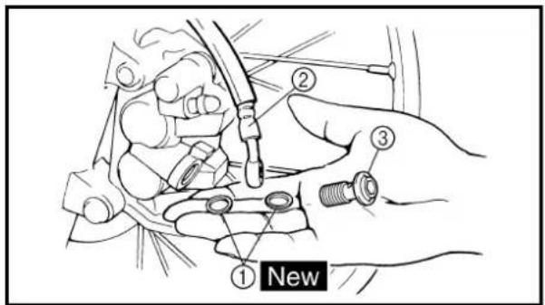
text_image
① New ② ③Brake hose
1. Install:
. Copper washer ①
New
- Brake hose ②
- Union bolt ③
26 Nm (2.6 m · kg, 19 ft · lb)

WARNING
Always use new copper washers.
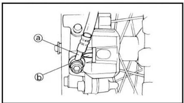
text_image
Technical diagram of a mechanical assembly with labeled parts (a) and (b)CAUTION:
Install the brake hose so that its pipe portion ① directs as show and lightly touches the projection ② on the brake caliper.
natural_image
Technical line drawing of a car suspension system with no visible text or symbols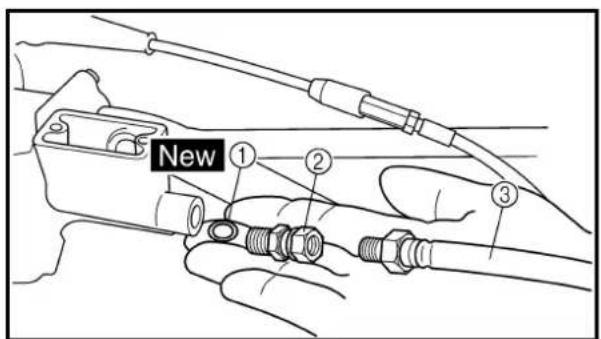
text_image
New ① ② ③-
Pass the brake hose through the cable guide ①.
-
Install:
. Copper washer ① New
• Joint ② 26 Nm (2.6 m · kg, 19 ft · lb)
- Brake hose ③
14 Nm (1.4 m · kg, 10 ft · lb)
WARNING
Always use a new copper washer.
NOTE:
When turning the joint over the brake hose, hold the brake hose so that it may not be twisted.
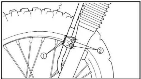
text_image
Technical diagram of a bicycle wheel assembly with labeled parts ① and ②- Install:
- Brake hose holder ①
. Bolt (brake hose holder) ②
7 Nm (0.7 m · kg, 5.1 ft · lb)
FREIN AVANT (TT-R125LW) VORDERRADBREMSE (TT-R125LW)

- Brake fluid Until the fluid level reaches "LOWER" level line @.

Recommended brake fluid: DOT #4
WARNING
. Use only the designated quality brake fluid:
otherwise, the rubber seals may deteriorate, causing leakage and poor brake performance.
- Refill with the same type of brake fluid; mixing fluids may result in a harmful chemical reaction and lead to poor performance.
- Be careful that water does not enter the brake master cylinder when refilling. Water will significantly lower the boiling point of the fluid and may result in vapor lock.
CAUTION:
Brake fluid may erode painted surfaces or plastic parts. Always clean up spilled fluid immediately.
- Air bleed:
- Brake system Refer to "BRAKE SYSTEM AIR BLEEDING" section in the CHAPTER 3.
- Inspect:
- Brake fluid level Fluid at lower level → Fill up. Refer to “BRAKE FLUID LEVEL INSPECTION” section in the CHAPTER 3.
Liquide de frein
1. Verser:
text_image
Technical diagram showing a mechanical assembly with labeled parts ① and ②, likely illustrating a tool or component assembly.4. Install:
• Diaphragm
- Brake master cylinder cap ①
- Screw (brake master cylinder cap) ②
2 Nm (0.2 m · kg, 1.4 ft · lb)
CAUTION:
After installation, while pulling in the lever, check whether there is any brake fluid leaking where the union bolts are installed respectively at the brake master cylinder and brake caliper.
4. Installer:
Extent of removal:
① Rear wheel removal
② Wheel bearing removal
③ Brake shoe plate assembly removal and disassembly
| Extent of removal Order Part name Q'ty Remarks | |||||
| Preparation for removal | REAR WHEEL AND DRUM BRAKEHold the machine by placing the suitable stand under the engine. | WARNINGSupport the machine securely so there is no danger of it falling over. | |||
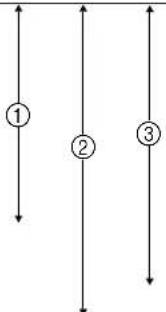 | 1 Brake rod 12 Axle nut 13 Drive chain puller (right) 14 Wheel axle 15 Drive chain puller (left) 16 Drive chain 17 Rear wheel 1 Refer to "REMOVAL POINTS".8 Collar (right) 19 Brake shoe plate assembly 110 Collar (left) | ||||
ROUE ARRIÈRE ET FREIN ARRIÈRE HINTERRAD UND HINTERRADBREMSE
ROUE ARRIÈRE ET FREIN ARRIÈRE
text_image
Technical diagram showing mechanical assembly with labeled parts, including a gear and chain components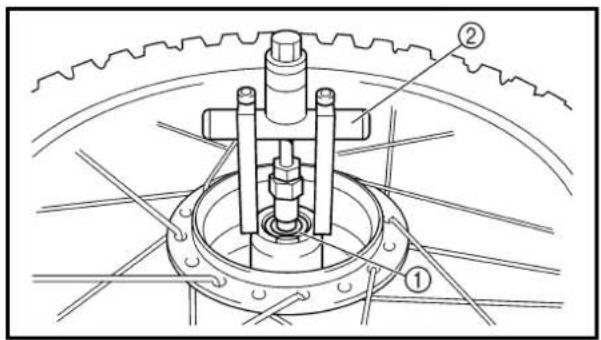
text_image
Technical diagram of a mechanical assembly with labeled parts ① and ②, showing gear and shaft components.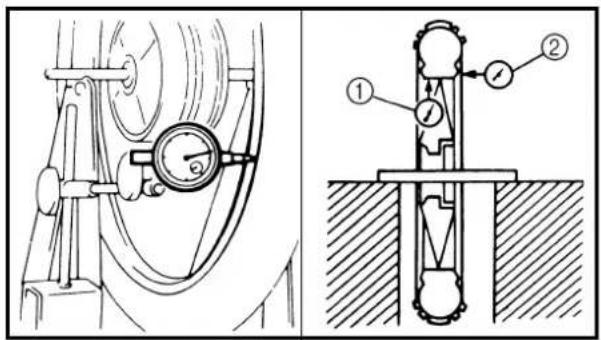
text_image
Technical diagram showing mechanical assembly with labeled components and motion indicators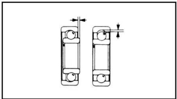
natural_image
Technical line drawing of two mechanical bearing components with dimension arrows (no text or symbols)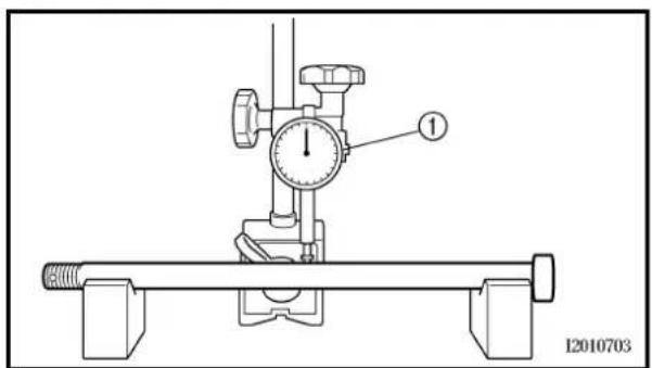
text_image
1 I2010703REMOVAL POINTS
EC523101
Rear wheel
- Remove:
- Wheel ①
NOTE:
Push the wheel forward and remove the drive chain ②.
EC513201
Wheel bearing (if necessary)
- Remove:
. Bearing ①
NOTE:
Remove the bearing using a general bearing puller ②.
INSPECTION
EC514100
Wheel
- Measure:
. Wheel runout
Out of limit → Repair/replace.

Wheel runout limit:
Radial ①: 2.0 mm (0.08 in)
Lateral ②: 2.0 mm (0.08 in)
- Inspect:
• Bearing
Rotate inner race with a finger.
Rough spot/seizure → Replace.
NOTE:
Replace the bearings, oil seal and wheel collar (wheel sprocket side) as a set.
EC514200
Wheel axle
- Measure:
- Wheel axle bends
Out of specification → Replace.
Use the dial gauge ①.

Wheel axle bending limit:
0.5 mm (0.020 in)
ROUE ARRIÈRE ET FREIN ARRIÈRE HINTERRAD UND HINTERRADBREMSE
CHAS

PIÈCES À DÉPOSER
Roue arrière
- Déposer:
• Roue ①
N.B.:
NOTE: The bending value is shown by one half of the dial gauge reading.
WARNING
Do not attempt to straighten a bent axle.
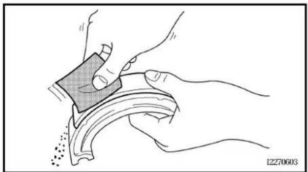
natural_image
Illustration of hands using a tool to clean or store items, no text or symbols present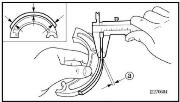
text_image
12270604Drum brake
- Inspect:
- Brake shoe lining surface Glazed areas → Polish. Use coarse sand paper.
NOTE: After polishing, wipe the polished particles with a cloth.
- Measure:
- Brake shoe lining thickness @ Out of specification → Replace.
| Brake shoe lining thickness: | ||
| Standard | ||
| 4.0 mm(0.16 in) | 2.0 mm(0.08 in) | |
NOTE: Replace the brake shoes and springs as a set if either is worn to the limit.
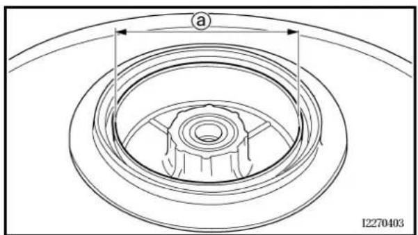
natural_image
Technical line drawing of a mechanical component with concentric rings and a central hub (no text or symbols)- Measure:
- Brake drum inside diameter ⓐ Out of specification → Replace.
 | Brake drum inside diameter: | |
| Standard | ||
| 110 mm(4.33 in) | 111 mm(4.37 in) | |
ROUE ARRIÈRE ET FREIN ARRIÈRE HINTERRAD UND HINTERRADBREMSE
N.B.:
Standard
HINWEIS:
- Brake drum inner surface. Oil/scratches → Remove.
| Oil | Use a rag soaked in lac-quer thinner or a solvent. |
| Scratches | Use a emery cloth (lightly and evenly polishing). |
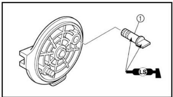
text_image
Technical diagram showing a mechanical component with labeled parts and connection pointASSEMBLY AND INSTALLATION
Brake shoe plate assembly
- Install:
- Brake camshaft ①
NOTE: Apply the lithium soap base grease on the brake camshaft.
- Check:
- Brake camshaft operation Unsmooth operation → Repair.
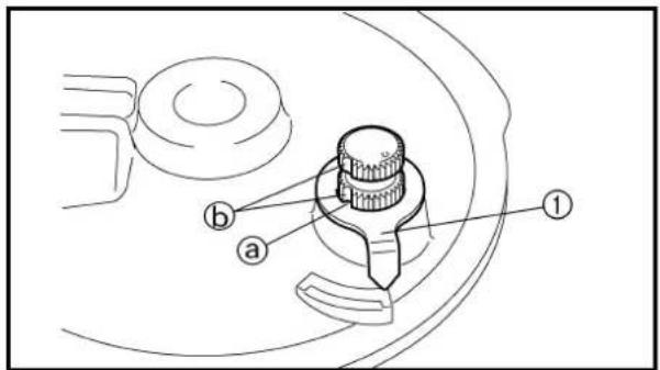
text_image
Technical diagram of a mechanical component with labeled parts a, b, and numbered point 1- Install:
• Wear indicator plate ①
NOTE: When installing the wear indicator plate to the brake camshaft align the projection ⓐ on the wear indicator plate with the slots Ⓑ on the brake camshaft.
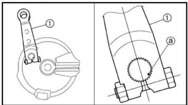
text_image
Technical diagram showing mechanical components with labeled parts, including a circular component and a gear-like structure.- Install:
• Brake camshaft lever ①
10 Nm (1.0 m · kg, 7.2 ft · lb)
NOTE: Install the brake camshaft lever in relation to the punch mark @ as shown.
ROUE ARRIÈRE ET FREIN ARRIÈRE HINTERRAD UND HINTERRADBREMSE

4. Examiner:
text_image
New ① ② ③ ② LS5. Install:
• Springs ① New
- Brake shoes ②
On brake shoe plate ③
NOTE:
- Apply the lithium soap base grease on the pivot pin.
- When installing the springs and brake shoes, take care not to damage the springs.
- When replacing the brake shoes, replace the springs as a set.
WARNING
Do not apply grease to the brake shoe linings.
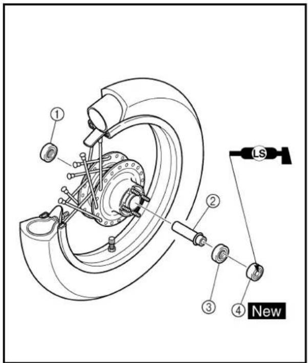
text_image
① ② ③ ④ New LSRear wheel
- Install:
• Wheel bearing ①
• Spacer ②
• Wheel bearing ③
. Oil seal ④ New
NOTE:
- Apply the lithium soap base grease on the oil seal lip when installing.
• Install the bearing with seal facing outward. - Use a socket that matches the outside diameter of the race of the bearing.
• Right side of bearing shall be installed first. - Install the oil seal with its manufacture's marks or numbers facing outward.
CAUTION:
Do not strike the inner race of the bearing. Contact should be made only with the outer race.
ROUE ARRIÈRE ET FREIN ARRIÈRE HINTERRAD UND HINTERRADBREMSE

5. Installer:
text_image
New ② ① ② New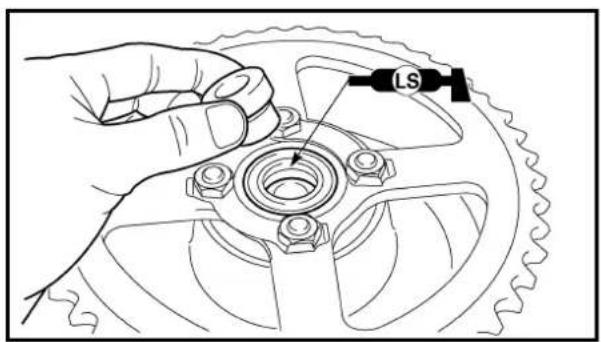
text_image
LS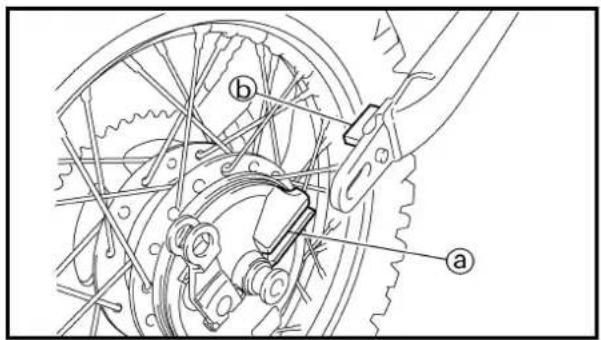
text_image
Technical diagram showing mechanical assembly with labeled parts a and b, likely from an engineering or manufacturing context.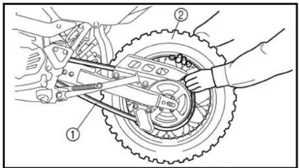
text_image
Technical diagram showing mechanical assembly with labeled parts, including a gear and chain components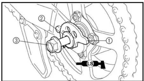
text_image
Technical diagram of a mechanical assembly with numbered components and a labeled component 'LS'2. Install:
- Wheel sprocket ①
- Lock washers ② New
26 Nm (2.6 m · kg, 19 ft · lb)
NOTE:
- Tighten the nuts in stage, using a crisscross pattern.
• Bend the lock washer tab.
3. Install:
• Collar (left)
• Brake shoe plate assembly
• Collar (right)
NOTE: \_\_\_\_
Apply the lithium soap base grease on the oil seal lip.
4. Install:
• Rear wheel
NOTE:
Make sure that the slot ⓐ on the brake shoe plate with the stopper ⓑ on the swingarm.
5. Install:
- Drive chain ①
NOTE:
Push the wheel ② forward and install the drive chain.
6. Install:
• Drive chain puller (left) ①
- Plain washer ②
.Wheel axle ③
NOTE:
- Apply the lithium soap base grease on the wheel axle.
- Insert the wheel axle from left side.
ROUE ARRIÈRE ET FREIN ARRIÈRE HINTERRAD UND HINTERRADBREMSE

2. Installer:
text_image
Technical diagram of a mechanical assembly with numbered components, likely illustrating a gear or bearing mechanism.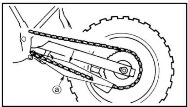
natural_image
Mechanical diagram of a chain drive system with gear and pulley components (no text or labels)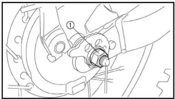
natural_image
Technical line drawing of a mechanical assembly with no visible text or symbols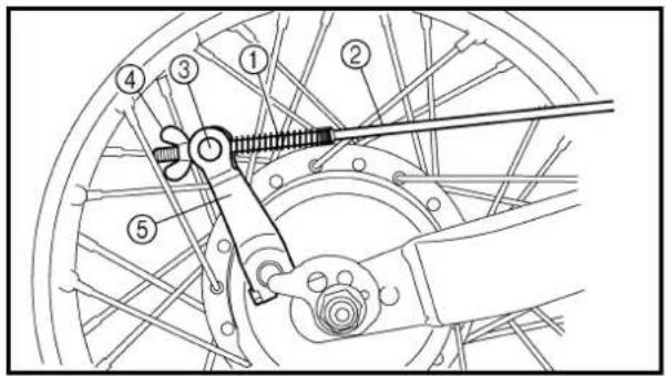
text_image
Technical diagram of a bicycle wheel assembly with numbered components for identification7. Install:
- Drive chain puller (right) ①
- Plain washer ②
- Axle nut ③
NOTE:
Temporarily tighten the axle nut at this point.
8. Adjust:
• Drive chain slack ⓐ
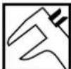
Drive chain slack: 35 \~ 50 mm (1.4 \~ 2.0 in)
Refer to "DRIVE CHAIN SLACK ADJUSTMENT" section in the CHAPTER 3.
9. Tighten:
• Axle nut ①
60 Nm (6.0 m · kg, 43 ft · lb)
10. Install:
• Spring ①
. Brake rod ②
• Pin ③
. Wing nut ④
On brake camshaft lever ⑤.
11.Adjust:
- Brake pedal free play
Refer to "REAR BRAKE ADJUSTMENT" section in the CHAPTER 3.
ROUE ARRIÈRE ET FREIN ARRIÈRE HINTERRAD UND HINTERRADBREMSE
CHAS

7. Installer:
Extent of removal: ① Front fork removal
| Extent of removal Order Part name Q'ty Remarks | |||
| Preparation for removal | FRONT FORK REMOVALHold the machine by placing the suitable stand under the engine.Front wheel Refer to “FRONT WHEEL AND FRONTBRAKE” section.Handlebar Refer to “HANDLEBAR” section. | WARNINGSupport the machine securely so there is no danger of it falling over. | |
| 1 Cap 12 Pinch bolt (upper bracket) 1 Only loosening.3 Cap bolt 1 Loosen when disassembling the front fork.4 Pinch bolt (lower bracket) 1 Only loosening.5 Front fork | 1 | ||
FOURCHE AVANT
Extent of removal: ① Oil seal removal ② Damper rod removal
| Extent of removal Order Part name Q'ty Remarks | |||
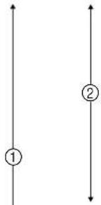 ↓ ↓ | FRONT FORK DISASSEMBLY1 Dust boot 12 Cap bolt 1 Refer to “REMOVAL POINTS”.3 Spacer 14 Washer 15 Fork spring 1 Drain the fork oil.6 Dust seal 17 Stopper ring 18 Bolt (damper rod) 19 Damper rod10 Inner tube11 Oil flow stopper12 Piston metal13 Oil seal14 Outer tube | 1111111 | Use special tool.Refer to “REMOVAL POINTS”. |
DÉMONTAGE DE LA FOURCHE AVANT
The front fork requires careful attention. So it is recommended that the front fork be maintained at the dealers.
CAUTION:
To prevent an accidental explosion of air, the following instructions should be observed:
The front fork with a built-in piston rod has a very sophisticated internal construction and is particularly sensitive to foreign material.
Use enough care not to allow any foreign material to come in when the oil is replaced or when the front fork is disassembled and reassembled.
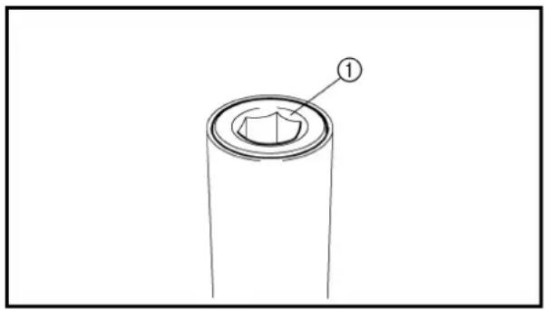
natural_image
Simple line drawing of a cylindrical object with a labeled section (①), no text or symbols present.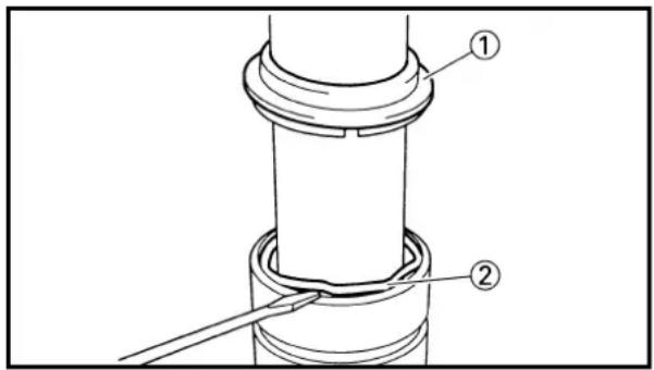
text_image
Technical diagram showing a mechanical assembly with labeled parts ① and ②, likely illustrating a pipe or connection mechanism.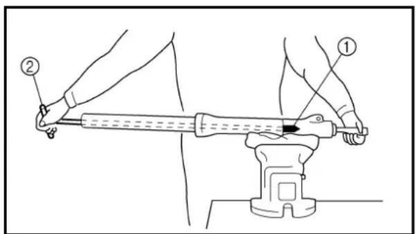
text_image
Diagram showing a person using a tool on an object, labeled with parts ① and ②, likely illustrating a manual or mechanical procedure.EC553000
REMOVAL POINTS
Cap bolt
- Remove:
- Cap bolt ①
From the inner tube.
NOTE:
Before removing the front fork from the machine, loosen the cap bolt.
Inner tube
- Remove:
• Dust seal ①
- Stopper ring ②
Using slotted-head screwdriver.
CAUTION:
Take care not to scratch the inner tube.
- Remove:
• Bolt (damper rod)
• Damper rod
- Inner tube
- Oil flow stopper
• Piston metal
NOTE:
Use the damper rod holder ① and the T-handle ② to lock the damper rod.
REMARQUE CONCERNANT LA MANIPULATION
N.B.:
natural_image
Simple line drawing of a cylindrical mechanical component with threaded end (no text or symbols)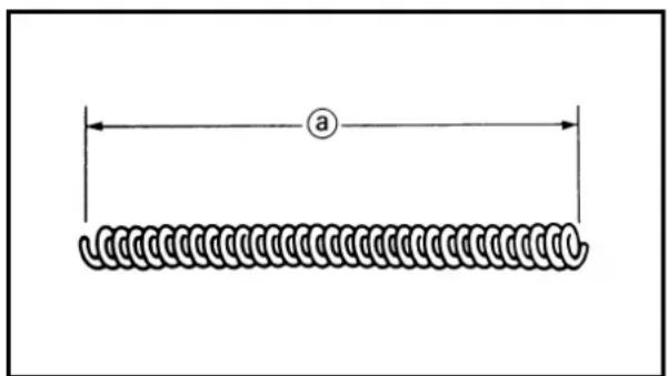
natural_image
Diagram of a coiled spring with labeled dimension 'a' (no text or symbols beyond label)3. Remove:
- Oil seal ① Using slotted-hand screwdriver.
CAUTION:
Take care not to scratch the outer tube.
EC554000
INSPECTION
Damper rod
1. Inspect:
- Damper rod Bend/damage → Replace damper rod.
CAUTION:
The front fork with a built-in piston rod has a very sophisticated internal construction and is particularly sensitive to foreign material.
Use enough care not to allow any foreign material to come in when the oil is replaced or when the front fork is disassembled and reassembled.
EC554400
Fork spring
1. Measure:
- Fork spring free length ⓐ Out of specification → Replace.
 | Fork spring free length: | |
| Standard | ||
| TT-R125: 327 mm(12.9 in)TT-R125LW:339 mm(13.3 in) | TT-R125: 322 mm(12.7 in)TT-R125LW:334 mm(13.1 in) | |

- Inner tube surface @ Score marks → Repair or replace. Use #1,000 grit wet sandpaper. Damaged oil lock piece → Replace.
- Inner tube bends Out of specification → Replace. Use the dial gauge ①.

Inner tube bending limit: 0.2 mm (0.008 in)
NOTE:
The bending value is shown by one half of the dial gauge reading.

WARNING
Do not attempt to straighten a bent inner tube as this may dangerously weaken the tube.
2. Inspect:
- Piston metal ① Wear/damage → Replace.
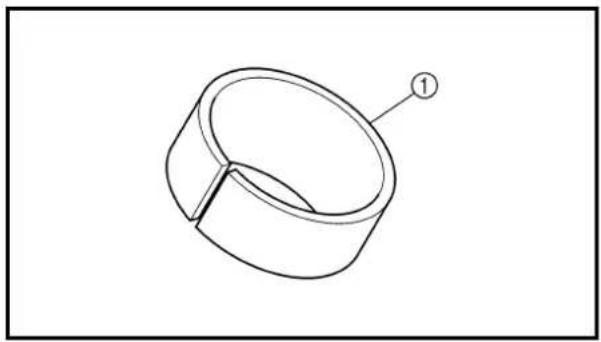
natural_image
Technical line drawing of a mechanical component with a labeled part (1), no text or symbols present.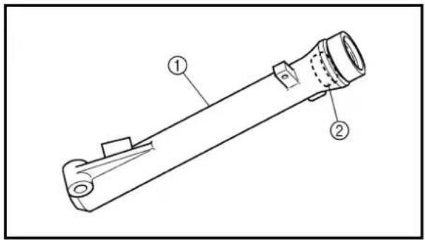
text_image
Technical diagram of a mechanical device with labeled parts ① and ②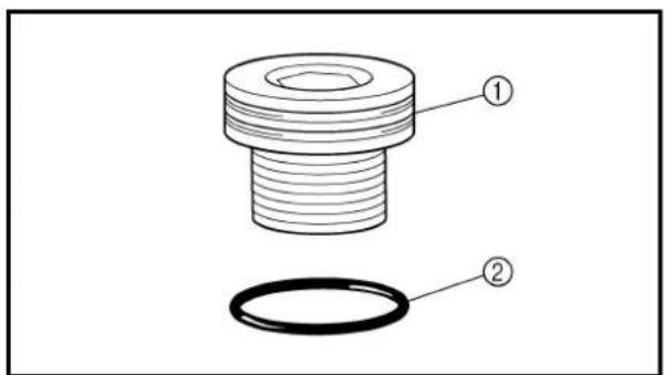
text_image
Technical diagram of a mechanical component with labeled parts ① and ②Outer tube
1. Inspect:
- Outer tube ① - Slide metal ② Score marks/wear/damage → Replace outer tube assembly.
Cap bolt
1. Inspect:
- Cap bolt ① - O-ring ② Wear/damage → Replace.
Tube plongeur
- Examiner:
ASSEMBLY AND INSTALLATION
Front fork assembly
- Wash the all parts in a clean solvent.
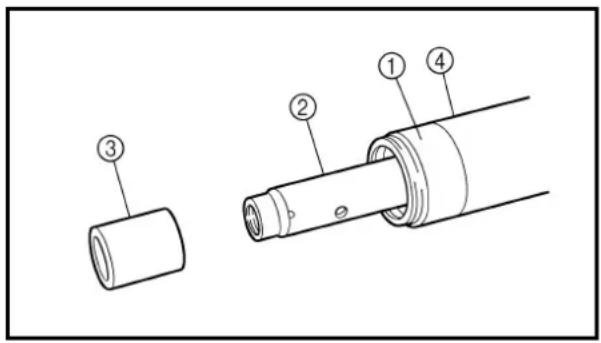
text_image
Technical diagram of a mechanical component with numbered parts labeled 1 to 4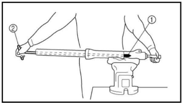
text_image
Diagram showing a person using a tool on a vise with labeled parts ① and ②, likely illustrating a physical or mechanical procedure.- Install:
• Piston metal ①
- Damper rod ②
• Oil flow stopper ③
On inner tube ④.
CAUTION:
To install the damper rod into the inner tube, hold the inner tube aslant. If the inner tube is held vertically, the damper rod may fall into it and be damaged.
- Install:
- Inner tube
On outer tube.
- Install:
• Copper washer
New
• Bolt (damper rod)

23 Nm (2.3 m · kg, 17 ft · lb)
NOTE:
Use the damper rod holder ① and the T-handle ② to lock the damper rod.

Damper rod holder:
YM-1300/90890-01294
T-handle:
YM-01326/90890-01326
REMONTAGE ET INSTALLATION
Fourche avant
text_image
① New ① ①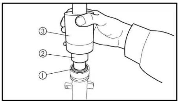
text_image
Technical diagram showing a hand operating a mechanical component with numbered parts labeled ①, ②, and ③.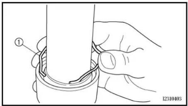
text_image
① I2310403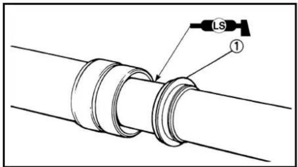
text_image
LS ①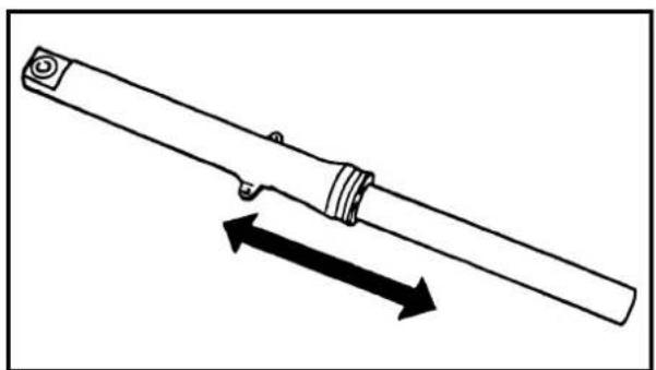
natural_image
Technical line drawing of a mechanical tool with two directional arrows indicating movement (no text or symbols)5. Install:
. Oil seal ①
New
NOTE:
- Apply the fork oil on the inner tube.
- When installing the oil seal, use vinyl seat @ with fork oil applied to protect the oil seal lip.
• Install the oil seal with its manufacturer's marks or number facing upside. - Press the oil seal into the outer tube with fork seal driver attachment (ø30) ② and fork seal driver weight ③.
Fork seal driver weight:
YM-33963/90890-01367
Fork seal driver attachment:
YM-33281/90890-01400
6. Install:
- Stopper ring ①
NOTE:
Fit the stopper ring correctly in the groove in the outer tube.
7. Install:
• Dust seal ①
NOTE:
Apply the lithium soap base grease on the inner tube.
8. Check:
• Inner tube smooth movement Tightness/binding/rough spots → Repeat the steps 2 to 7.
5. Installer:
text_image
Technical diagram showing a pipe being inserted into a cylindrical component, labeled with number 1-
Compress the front fork fully.
-
Fill:
- Front fork oil ①

Recommended oil: Fork oil 10W or equivalent Quantity (each front fork leg): TT-R125: 159 cm ^3 (5.60 Imp oz, 5.38 US oz) TT-R125LW: 156 cm ^3 (5.49 Imp oz, 5.27 US oz)
CAUTION:
- Be sure to use recommended fork oil. If other oils are used, they may have an excessively adverse effect on the front fork performance.
-
Never allow foreign materials to enter the front fork.
-
After filling, pump the inner tube slowly up and down more than 10 times to distribute the fork oil.
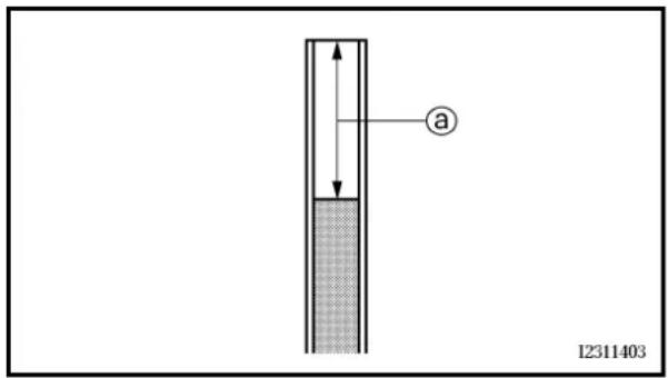
text_image
a I231140312.Measure:
• Oil level ⓐ
Out of specification → Adjust.

Standard oil level: TT-R125: 122 mm (4.80 in) TT-R125LW: 130 mm (5.12 in) From the top of the inner tube, with the inner tube fully compressed, and without the fork spring.
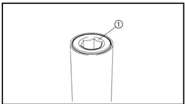
natural_image
Technical line drawing of a cylindrical mechanical component with a labeled part (1), no text or symbols present.- Install:
• Fork spring
• Washer
- Spacer
- Cap bolt ①
• Dust boot
NOTE:
Temporarily tighten the cap bolt.
• Temporarily tighten the pinch bolt (lower bracket).
- Do not tighten the pinch bolt (upper bracket) yet.
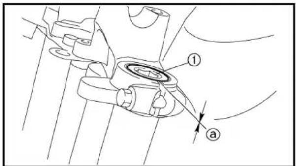
text_image
Technical diagram showing mechanical assembly with labeled parts 1 and a, likely illustrating a component or assembly.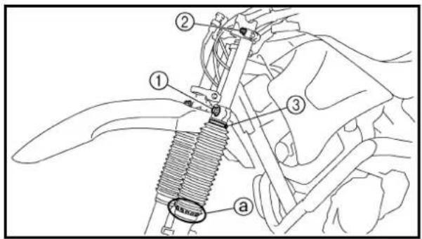
text_image
Technical diagram of a mechanical assembly with labeled parts including a spring and numbered components- Tighten:
- Cap bolt ①
23 Nm (2.3 m · kg, 17 ft · lb)
- Adjust:
- Front fork top end ⓐ

Front fork top end (standard) ⓐ: Zero mm (Zero in)
- Tighten:
• Pinch bolt (lower bracket) ①
60 Nm (6.0 m · kg, 43 ft · lb)
• Pinch bolt (upper bracket) ②
25 Nm (2.5 m · kg, 18 ft · lb)
- Screw (dust boot) ③
NOTE:
- Make sure that the dust boot holes ⓐ are positioned outward.
- Tighten the screw (dust boot) until the top of the dust boot is touching the lower bracket.
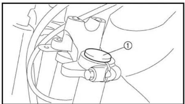
natural_image
Technical line drawing of a mechanical assembly with labeled component (no text or symbols present)- Install:
- Cap ①
Installation
- Installer:
- Fourche avant
N.B.:
Extent of removal:
① Handlebar removal
| Extent of removal Order Part name Q'ty Remarks | ||||
| Preparation for removal | HANDLEBAR REMOVALNumber plate | |||
| 1 | 1 Clutch cable 12 Clutch lever 13 Engine stop switch 14 Front brake cable 15 Front brake lever 16 Grip cap (lower) 17 Grip cap (upper) 18 Throttle cable 19 Throttle grip assembly 110 Collar 111 Handlebar grip (left)12 Handlebar holder13 Handlebar | 1 Refer to “REMOVAL POINTS”.21 | ||
GUIDON
TT-R125
Extent of removal:
① Handlebar removal
| Extent of removal Order Part name Q'ty Remarks | ||||
| Preparation for removal | HANDLEBAR REMOVALNumber plate | |||
| 1 | 1 Clutch cable 12 Clutch lever 13 Engine stop switch 14 Brake master cylinder 1 Refer to “REMOVAL POINTS”.5 Grip cap (lower) 16 Grip cap (upper) 17 Throttle cable 18 Throttle grip assembly 1 | |||
TT-R125LW
| Extent of removal Order Part name Q'ty Remarks | ||||
| 1 | 9 Collar 110 Handlebar grip (left) 1 Refer to “REMOVAL POINTS”.11 Upper handlebar holder 212 Handlebar | 1 | ||
text_image
Technical diagram of a mechanical component with three labeled parts, showing exploded and assembled views.Extent of removal:
① Throttle grip assembly disassembly
| Extent of removal Order Part name Q'ty Remarks | ||||
 | 123 | THROTTLE GRIP ASSEMBLYDISASSEMBLYHandlebar grip (right) 1 Refer to “REMOVAL POINTS”.Collar 2Tube guide | 1 | |
DÉMONTAGE DE LA POIGNÉE DES GAZ
text_image
Technical diagram of a mechanical assembly with labeled parts and directional indicatorsREMOVAL POINTS
Brake master cylinder (TT-R125LW)
-
Remove:
-
Brake master cylinder bracket ①
- Brake master cylinder ②
CAUTION:
- Do not let the brake master cylinder hang on the brake hose.
- Keep the brake master cylinder cap side horizontal to prevent air from coming in.
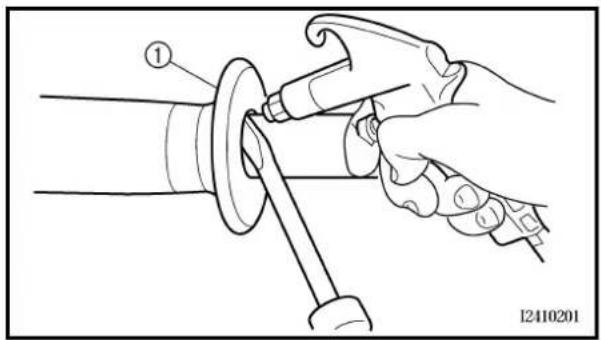
natural_image
Illustration of a hand using a tool to adjust or install a mechanical component, no text or symbols present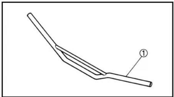
natural_image
Line drawing of a bent tool or blade with a labeled point (1) on the end, no text or symbols present.Handlebar grip
- Remove:
• Handlebar grip ①
NOTE:
Blow in air between the handlebar or tube guide and the grip. Then remove the grip which has become loose.
INSPECTION
Handlebar
- Inspect:
. Handlebar ①
Bends/cracks/damage → Replace.
WARNING
Do not attempt to straighten a bent handlebar as this may dangerously weaken the handlebar.
PIÈCES À DÉPOSER
text_image
Technical diagram of a mechanical component with labeled parts ①, ②, and ③ASSEMBLY AND INSTALLATION
Throttle grip assembly
1. Install:
- Collar ①
- Handlebar grip (right) ②
Apply the adhesive on the tube guide ③.
NOTE:
Before applying the adhesive, wipe off grease or oil on the tube guide surface ⓐ with a lacquer thinner.
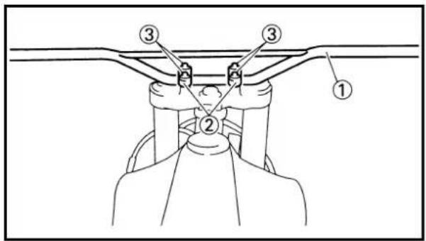
text_image
Technical diagram showing a mechanical assembly with numbered components labeled 1, 2, and 3.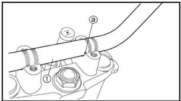
text_image
Technical diagram showing mechanical assembly with labeled parts a and 1, likely for assembly or maintenance instructions.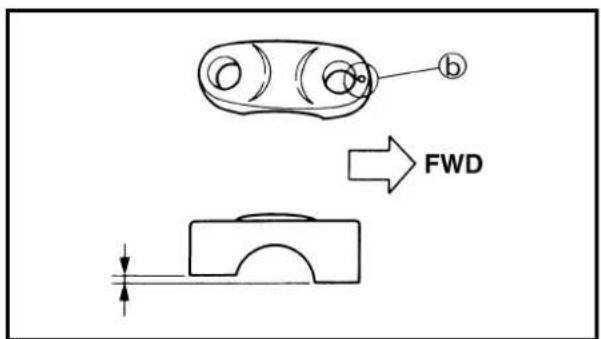
text_image
b FWDHandlebar
1. Install:
- Handlebar ①
• Handlebar holder ②
• Bolt (handlebar holder) ③
23 Nm (2.3 m · kg, 17 ft · lb)
NOTE:
- Align the punched mark @ on the handlebar with the upper surface of the handlebar holder on the upper bracket.
- The handlebar holder should be installed with the punched mark ⑥ forward.
- First tighten the bolts on the front side of the handlebar holder, and then tighten the bolts on the rear side.
REMONTAGE ET INSTALLATION
text_image
Diagram showing a hand holding a circular object with labeled parts ①, ②, and ③, likely illustrating a mechanical or anatomical procedure.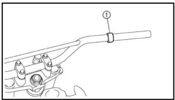
natural_image
Technical line drawing of a mechanical assembly with a handle and bolt (no text or symbols)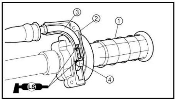
text_image
Technical diagram of a mechanical assembly with numbered components and a labeled component 'LS'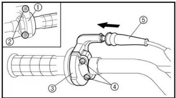
text_image
Technical diagram of a pipe welding or piping connection with labeled parts and an inset showing a close-up detail.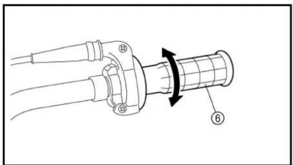
natural_image
Technical diagram of a mechanical component with labeled parts (no text or symbols present)2. Install:
- Handlebar grip (left) ① Apply the adhesive to the handlebar ②.
NOTE:
Before applying the adhesive, wipe off grease or oil on the handlebar surface @ with a lacquer thinner.
3. Install:
• Collar ①
4. Install:
• Throttle grip assembly ①
• Grip cap (upper) ②
- Throttle cables ③
On tube guide ④.
NOTE:
Apply the lithium soap base grease on the throttle cable end and tube guide cable winding portion.
5. Install:
- Throttle cable cap ①
• Screw (throttle cable cap) ②
2 Nm (0.2 m · kg, 1.4 ft · lb)
• Grip cap (lower) ③ - Screw (grip cap) ④
4 Nm (0.4 m · kg, 2.9 ft · lb) - Cover (grip cap) ⑤
WARNING
After tightening the screws, check that the throttle grip ⑥ moves smoothly. If it does not, retighten the bolts for adjustment.
2. Installer:
text_image
Technical diagram of a mechanical device with numbered components and labeled parts, including a 'LS' component.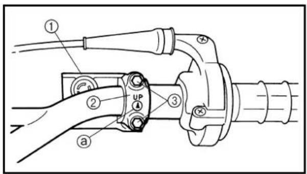
text_image
Technical diagram of a mechanical assembly with labeled parts and connection points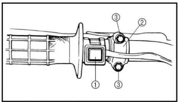
text_image
Technical diagram of a mechanical assembly with numbered components, likely illustrating a valve or clamp mechanism.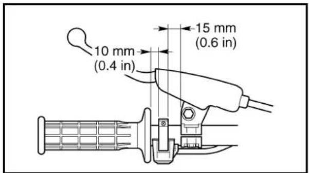
text_image
10 mm (0.4 in) 15 mm (0.6 in)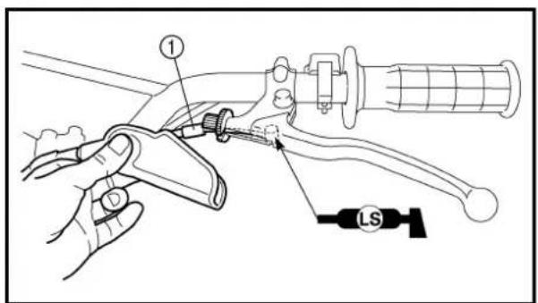
text_image
Technical diagram showing a hand operating a mechanical lever with labeled component 'LS'6. Install:
TT-R125
• Front brake lever holder ①
• Bolts (front brake lever holder) ②
4 Nm (0.4 m · kg, 2.9 ft · lb)
- Front brake cable ③
- Clamp
NOTE:
Apply the lithium soap base grease on the front brake cable end.
TT-R125LW
• Brake master cylinder ①
- Brake master cylinder bracket ②
• Bolt (brake master cylinder bracket) ③
9 Nm (0.9 m · kg, 6.5 ft · lb)
NOTE:
- Install the bracket so that the arrow mark @ face upward.
- First tighten the bolts on the upper side of the brake master cylinder bracket, and then tighten the bolts on the lower side.
7. Install:
• Engine stop switch ①
- Clutch lever holder ②
• Bolts (clutch lever holder) ③
4 Nm (0.4 m · kg, 2.9 ft · lb)
NOTE:
• The engine stop switch and clutch lever holder should be installed according to the dimensions shown.
• Pass the engine stop switch lead in the middle of the clutch lever holder.
8. Install:
- Clutch cable ①
- Clamp
NOTE:
Apply the lithium soap base grease on the clutch cable end.
9. Adjust:
- Brake lever free play Refer to "FRONT BRAKE ADJUSTMENT" section in the CHAPTER 3.
- Clutch lever free play Refer to "CLUTCH ADJUSTMENT" section in the CHAPTER 3.
6. Installer:
TT-R125
Extent of removal: ① Lower bracket removal ② Bearing removal
| Extent of removal Order Part name Q'ty Remarks | ||||
| Preparation for removal | STEERING REMOVALHold the machine by placing the suitable stand under the engine.Front forks Refer to “FRONT FORK” section.Handlebar Refer to “HANDLEBAR” section.Front fender | WARNINGSupport the machine securely so there is no danger of it falling over. | ||
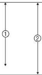 | 1 Steering stem nut 12 Upper bracket 13 Special washer 14 Upper ring nut 15 Rubber washer 16 Lower ring nut 17 Lower bracket 18 Bearing cover | 1 | Use special tool.Refer to “REMOVAL POINTS”. | |
DIRECTION
| Extent of removal Order Part name Q'ty Remarks | ||||
| 2 | 9 Bearing inner race (upper) 110 Bearing (upper) 111 Bearing outer race (upper) 112 Bearing outer race (lower) 113 Bearing (lower) | 1 | Refer to “REMOVAL POINTS”.Refer to “REMOVAL POINTS”. | |
text_image
Technical diagram of a mechanical assembly with labeled parts ① and ②FC563000
REMOVAL POINTS
EC563202
Ring nut
- Remove:
• Ring nut ①
Use the steering nut wrench ②.

Steering nut wrench: YU-33975/90890-01403

WARNING
Support the steering shaft so that it may not fall down.
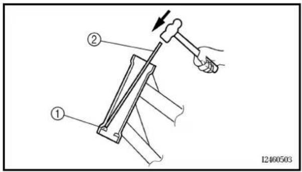
text_image
Technical diagram showing a hand operating a hammer tool with labeled parts ① and ②, likely illustrating a mechanical or electrical assembly.Bearing race
- Remove:
• Bearing race ①
Remove the bearing race using long rod ② and the hammer.
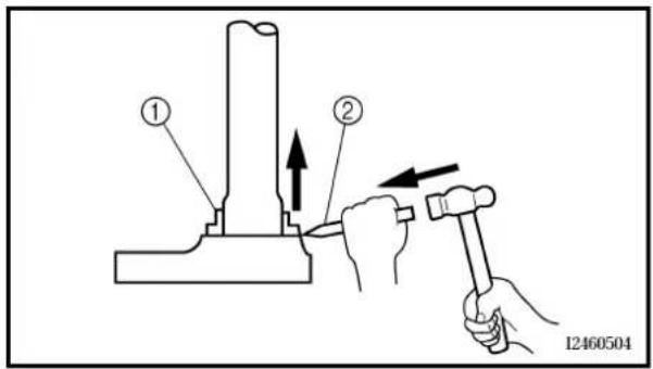
text_image
Technical diagram showing two hands using a hammer to adjust a mechanical component, labeled with parts ① and ②.EC563300
Bearing (lower)
- Remove:
• Bearing (lower) ①
Use the floor chisel ②.
CAUTION:
Take care not to damage the steering shaft thread.
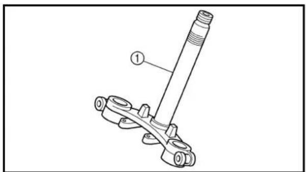
text_image
Technical diagram of a mechanical assembly with labeled parts, showing a shaft and flange assembly.EC564000
INSPECTION
Steering stem
- Inspect:
• Steering stem ①
Bend/damage → Replace.
PIÈCES À DÉPOSER
Écrou crénelé
- Déposer:
- Écrou crénelé ①
Bearing and bearing race
-
Wash the bearings and bearing races with a solvent.
-
Inspect:
• Bearing
• Bearing race
Pitting/damage → Replace bearings and bearing races as a set.
Install the bearing in the bearing races.
Spin the bearings by hand. If the bearings hang up or are not smooth in their operation in the bearing races, replace bearings and bearing races as a set.
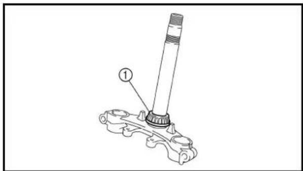
text_image
Technical diagram of a mechanical assembly with labeled component 1EC565000
ASSEMBLY AND INSTALLATION
Lower bracket
- Install:
• Bearing (lower) ①
NOTE:
Apply the lithium soap base grease on the dust seal lip and bearing inner circumference.
- Install:
• Bearing outer race (lower)
• Bearing outer race (upper)
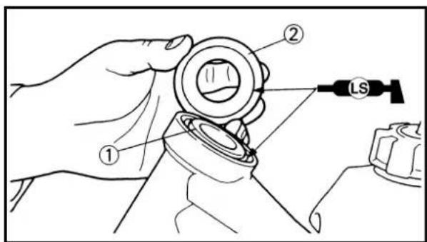
text_image
Technical diagram showing a hand holding a mechanical component with labeled parts and a 'LS' label pointing to it.- Install:
• Bearing (upper)
• Bearing inner race ①
• Bearing cover ②
NOTE:
Apply the lithium soap base grease on the bearing and bearing cover lip.
text_image
Technical diagram showing a hand holding a device with labeled parts and a 'LS' indicator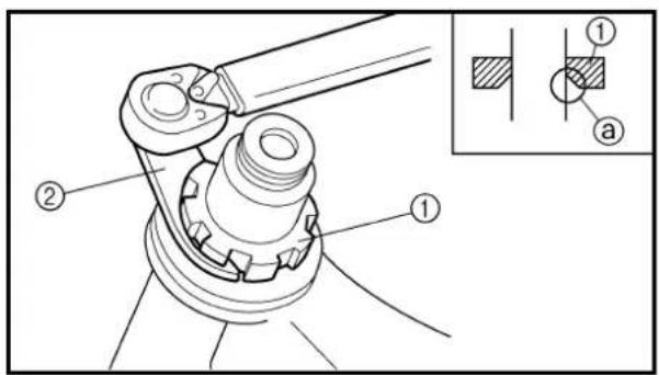
text_image
Technical diagram of a mechanical assembly with labeled parts and an inset showing cross-sectional view.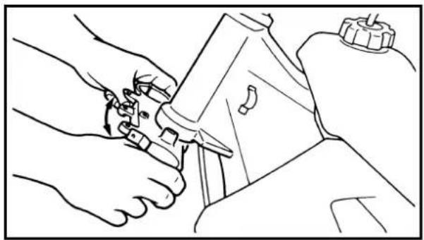
natural_image
Line drawing of hands using a tool to adjust or install a mechanical component (no text or symbols present)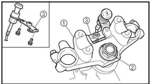
text_image
Technical diagram of a mechanical assembly with numbered parts and an inset view showing a component labeled ③.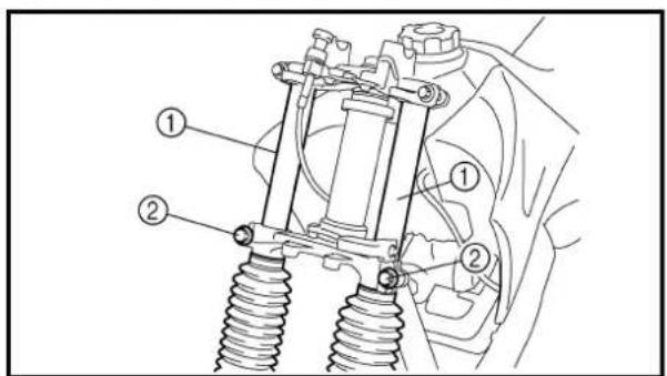
text_image
Technical diagram of a vehicle suspension system with labeled components4. Install:
• Lower bracket ①
NOTE:
Apply the lithium soap base grease on the bearing.
5. Install:
- Lower ring nut ①
Install the lower ring nut with its larger chamfered portion @ facing downward.
Refer to "STEERING HEAD INSPECTION AND ADJUSTMENT" section in the CHAPTER 3.
- Check the steering shaft by turning it lock to lock. If there is any binding, remove the steering shaft assembly and inspect the steering bearings.
7. Install:
• Upper bracket ①
• Steering stem nut ②
• Starter knob bracket ③
10 Nm (1.0 m · kg, 7.2 ft · lb)
NOTE:
Do not tighten the steering stem nut yet.
8. Install:
- Front forks ①
NOTE:
• Temporarily tighten the pinch bolts (lower bracket) ②.
- Do not tighten the pinch bolts (upper bracket) yet.
4. Installer:
• Té inférieur ①
N.B.:
text_image
Technical diagram of a mechanical assembly with numbered components, likely for assembly or maintenance instructions.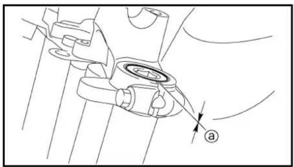
natural_image
Technical line drawing of a mechanical assembly with no visible text or symbols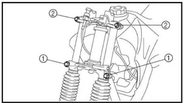
text_image
Technical diagram of a vehicle suspension system with labeled components9. Tighten:
• Steering stem nut ①
110 Nm (11.0 m · kg, 80 ft · lb)
10. Install:
- Cap ②
- After tightening the nut, check the steering for smooth movement. If not, adjust the steering by loosening the ring nut little by little.
12.Adjust:
- Front fork top end ⓐ

Front fork top end (standard) ⓐ: Zero mm (Zero in)
13.Tighten:
• Pinch bolts (lower bracket) ①
60 Nm (6.0 m · kg, 43 ft · lb)
• Pinch bolts (upper bracket) ②
25 Nm (2.5 m · kg, 18 ft · lb)
9. Serrer:
Extent of removal: ① Swingarm removal
| Extent of removal Order Part name Q'ty Remarks | |||
| Preparation for removal | SWINGARM REMOVALHold the machine by placing the suitable stand under the engine.Rear wheel Refer to “REAR WHEEL AND REARBRAKE” section. | ||
| 1 Drive chain tensioner (upper) 12 Drive chain tensioner (lower) 13 Bolt (connecting arm-frame) 14 Bolt (rear shock absorber-relay arm) 1 Hold the swingarm.5 Pivot shaft 16 Swingarm 1 | |||
BRAS OSCILLANT
② Connecting arm removal and disassembly
③ Relay arm removal and disassembly
| Extent of removal Order Part name Q'ty Remarks | |||
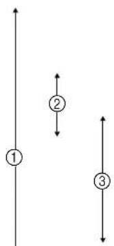 ↓ ↓ | SWINGARM DISASSEMBLY1Drive chain guard 12Drive chain support 13Drive chain guide 14Dust cover 45Collar 16Connecting arm 17Oil seal 28Collar 29Dust cover 210Bushing 111Relay arm 112Dust cover 213Bushing 114Swingarm | 1 | |
DÉMONTAGE DU BRAS OSCILLANT
text_image
Technical diagram showing a mechanical assembly with labeled component 1 and directional arrow indicating force or direction.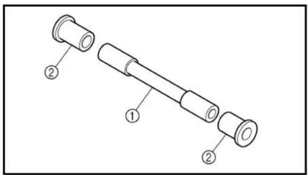
text_image
Technical diagram of a mechanical component with labeled parts ① and ②REMOVAL POINTS
Bushing
- Remove:
• Bushing ①
NOTE:
Remove the bushing by pressing.
INSPECTION
Wash the bushings, collars, and covers in a solvent.
Swingarm
-
Inspect:
-
Bushing ①
• Bushing ②
Damage/pitting → Replace bushings as a set.
- Inspect:
• Dust cover
Damage → Replace.
- Inspect:
• Swingarm
Damage/bends/cracks → Replace.
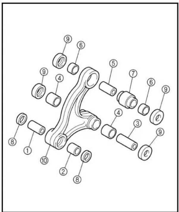
text_image
Technical diagram of a mechanical assembly with numbered parts for identificationRelay arm
- Inspect:
• Collar ①
• Bushing ②
Damage/pitting → Replace collar and bushing as a set.
• Bushing ③
• Bushing ④
Damage/pitting → Replace bushings as a set.
• Collar ⑤
• Bushing ⑥
• Bushing ⑦
Damage/pitting → Replace collars and bushing as a set.
- Inspect:
. Oil seal ⑧
• Dust cover ⑨
Damage → Replace.
- Inspect:
• Relay arm ⑩
Damage/bends/cracks → Replace.
PIÈCES À DÉPOSER
Bague
- Déposer:
• Bague ①
N.B.:
text_image
Technical diagram of a mechanical assembly with numbered parts for identificationConnecting arm
-
Inspect:
-
Collar ①
• Bushing ②
Damage/pitting → Replace collar and bushings as a set.
- Inspect:
• Dust cover ③
Damage → Replace.
- Inspect:
- Connecting arm ④
Damage/bends/cracks → Replace.
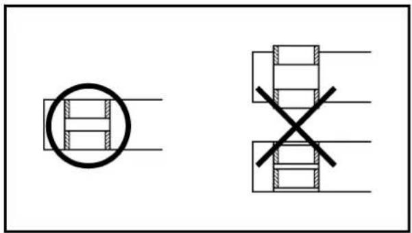
natural_image
Pure electrical circuit lines without any symbolsEC575000
ASSEMBLY AND INSTALLATION
Bushing
- Install:
• Bushing
NOTE:
Make sure to press in the bushing so that they are flush with the surface of the connecting arm and relay arm.
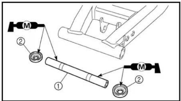
text_image
Technical diagram showing mechanical assembly with labeled components and parts, including a cylindrical component and two motor arms.Swingarm assembly
- Install:
• Bushing ①
• Dust covers ②
On swingarm.
NOTE:
Apply the molybdenum disulfide grease on the bushing and dust cover lip.
Bras de raccordement
text_image
Technical diagram of a mechanical assembly with numbered components and labeled parts (M)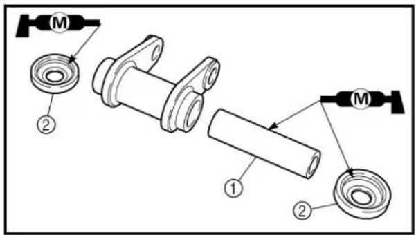
text_image
Technical diagram showing exploded view of mechanical components with labeled parts and assembly indicators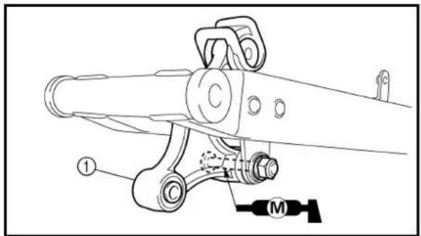
text_image
Technical diagram of a mechanical assembly with labeled parts and a motor symbol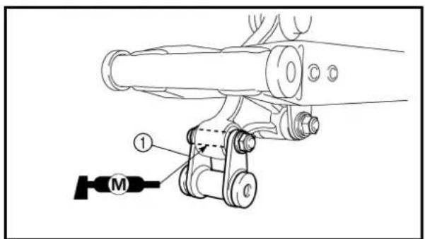
text_image
Technical diagram of a mechanical assembly with labeled parts and a motor symbol2. Install:
. Oil seals ①
• Collars ②
• Bushing ③
• Dust covers ④
• Dust covers ⑤
• Rubber boot ⑥
On relay arm.
NOTE:
Apply the molybdenum disulfide grease on the bushing, collar, oil seal lip and dust cover lip.
3. Install:
• Collar ①
• Dust covers ②
On connecting arm.
NOTE: \_\_\_\_
Apply the molybdenum disulfide grease on the collar and dust cover lip.
4. Install:
• Relay arm ①
• Bolt (relay arm)
- Plain washer
• Nut (relay arm)
53 Nm (5.3 m · kg, 38 ft · lb)
On swingarm.
NOTE:
Apply the molybdenum disulfide grease on the bolt (relay arm).
5. Install:
- Connecting arm ①
• Bolt (connecting arm) - Plain washer
• Nut (connecting arm)
35 Nm (3.5 m · kg, 25 ft · lb)
On relay arm.
NOTE:
Apply the molybdenum disulfide grease on the bolt (connecting arm).
2. Installer:
text_image
Technical diagram of a mechanical device with labeled parts ① and ②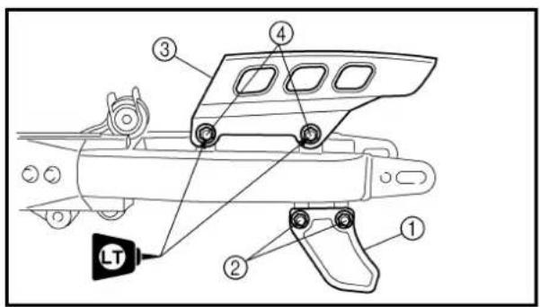
text_image
Technical diagram of a mechanical device with numbered components and a labeled component 'LT'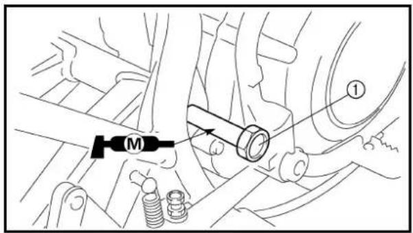
text_image
Technical diagram showing mechanical assembly with labeled component 'M' and numbered marker '①'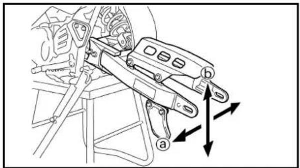
text_image
Technical diagram showing mechanical assembly with labeled parts (a, b) and directional arrows indicating motion or force vectors.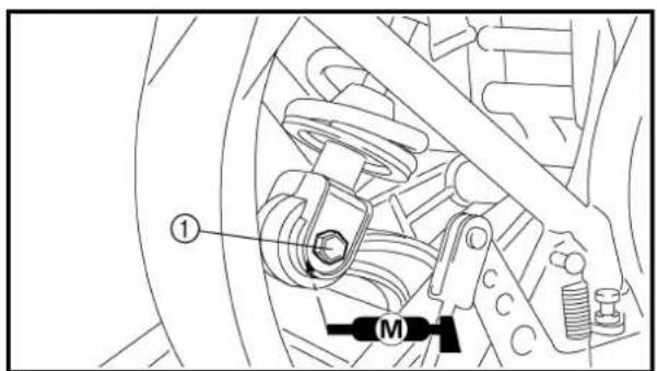
text_image
Technical diagram of a mechanical assembly with labeled parts and a motor indicator6. Install:
• Drive chain guide ①
• Collars
• Bolts (drive chain guide) ②
7 Nm (0.7 m · kg, 5.1 ft · lb)
7. Install:
- Drive chain support ①
• Collars
• Bolts (drive chain support) ②
7 Nm (0.7 m · kg, 5.1 ft · lb)
• Drive chain guard ③
• Bolts (drive chain guide) ④
7 Nm (0.7 m · kg, 5.1 ft · lb)
Installation
1. Install:
• Swingarm
• Pivot shaft ①
- Plain washer
• Nut (pivot shaft)
53 Nm (5.3 m · kg, 38 ft · lb)
NOTE:
Apply the molybdenum disulfide grease on the pivot shaft.
2. Check:
- Swingarm side play @ Free play exists → Replace bushing.
- Swingarm up and down movement ⑥ Unsmooth movement/binding/rough spots → Grease or replace bushing.
3. Install:
• Bolt (rear shock absorber - relay arm) ①
- Plain washer
• Nut (rear shock absorber-relay arm)
35 Nm (3.5 m · kg, 25 ft · lb)
NOTE:
Apply the molybdenum disulfide grease on the bolt (rear shock absorber - relay arm).
6. Installer:
text_image
Technical diagram of a mechanical assembly with labeled components and directional arrow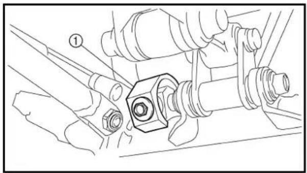
natural_image
Technical line drawing of a mechanical assembly with bolts and a central component (no text or symbols)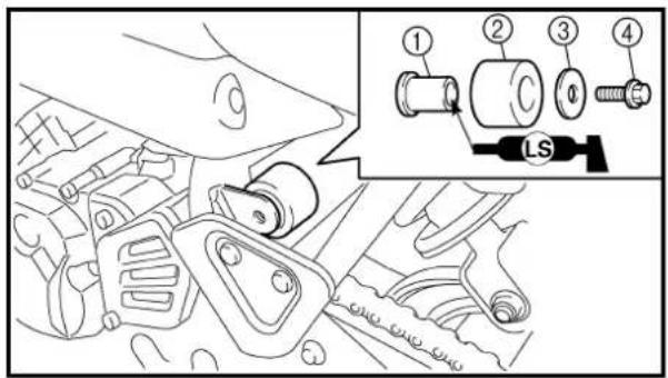
text_image
Technical diagram showing engine component assembly with numbered parts and a close-up of the internal components labeled 'LS'.4. Install:
• Bolt (connecting arm-frame) ①
- Plain washer
• Nut (connecting arm-frame)
35 Nm (3.5 m · kg, 25 ft · lb)
NOTE:
Apply the molybdenum disulfide grease on the bolt (connecting arm - frame).
5. Install:
• Drive chain tensioner (lower) ①
• Collar
• Bolt [drive chain tensioner (lower)]
7 Nm (0.7 m · kg, 5.1 ft · lb)
6. Install:
• Bushing ①
• Drive chain tensioner (upper) ②
- Plain washer ③
• Bolt [drive chain tensioner (upper)] ④
23 Nm (2.3m · kg, 17 ft · lb)
NOTE:
Apply the lithium soap base grease on the bushing inner surface.
4. Installer:
• Boulon (bras de raccordement – cadre) ①
• Rondelle plate
- Écrou (bras de raccordement – cadre)
Extent of removal: ① Rear shock absorber assembly removal
| Extent of removal Order Part name Q'ty Remarks | |||
| Preparation for removal | REAR SHOCK ABSORBER ASSEMBLY REMOVALHold the machine by placing the suitable stand under the engine.Seat and side covers Refer to “SEAT, FUEL TANK AND SIDE COVERS” section. | ||
| 1 Bolt (rear shock absorber assembly-relay arm)2 Bolt (rear shock absorber assembly-frame)3 Bushing 1 Refer to “REMOVAL POINTS”.4 Rear shock absorber assembly 1 | 1 Hold the swingarm.1 | ||
COMBINÉ RESSORT-AMORTISSEUR ARRIÈRE
This rear shock absorber contains high-pressure nitrogen gas. To prevent the danger of explosion, read and understand the following information before handling the shock absorber.
The manufacturer can not be held responsible for property damage or personal injury that may result from improper handling.
- Never tamper or attempt to open the rear shock absorber.
- Never throw the rear shock absorber into an open flame or other high heat. The rear shock absorber may explode as a result of nitrogen gas expansion and/or damage to the hose.
- Be careful not to damage any part of the rear shock absorber. A damaged rear shock absorber will impair the damping performance or cause a malfunction.
- Take care not to scratch the contact surface of the piston rod with the cylinder; or oil could leak out.
- When scrapping the rear shock absorber, follow the instruction on disposal.
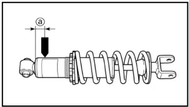
text_image
aNOTES ON DISPOSAL (YAMAHA DEALERS ONLY)
Gas pressure must be released before disposing of a rear shock absorber and gas cylinder. To release the gas pressure, drill a 2 \~ 3-mm (0.08 \~ 0.12-in) hole through the gas cylinder at a point 12 mm (0.5 in) @ from its end as shown.
WARNING
Wear eye protection to prevent eye damage from released gas or metal chips.
REMARQUE CONCERNANT LA MANIPULATION
AVERTISSEMENT
text_image
Technical diagram showing a mechanical assembly with labeled component ① and directional arrow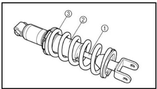
text_image
Technical diagram of a car suspension system with numbered components labeled ①, ②, and ③.FC583000
REMOVAL POINTS
Bushing
- Remove:
• Bushing ①
NOTE:
Remove the bushing by pressing.
EC584000
INSPECTION
Rear shock absorber assembly
- Inspect:
- Damper rod ① Bends/damage → Replace rear shock absorber assembly
- Shock absorber ② Oil leaks → Replace rear shock absorber assembly Gas leaks → Replace rear shock absorber assembly
- Spring ③ Damage → Replace rear shock absorber assembly Fatigue → Replace rear shock absorber assembly Move spring up and down.
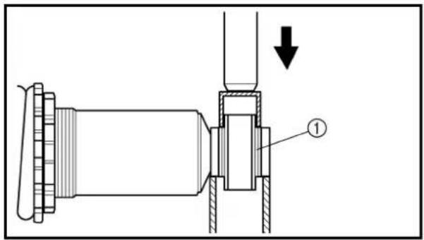
text_image
Technical diagram showing a mechanical assembly with labeled component ① and directional arrow indicating motion or force.EC585000
ASSEMBLY AND INSTALLATION
Bushing
- Install:
• Bushing ①
NOTE:
Install the bushing by pressing.
COMBINÉ RESSORT-AMORTISSEUR ARRIÈRE HINTERRAD-STOSSDÄMPFER

PIÈCES À DÉPOSER
Bague
- Déposer:
• Bague ①
N.B.:
text_image
Technical diagram of a mechanical assembly with labeled parts and a motor symbol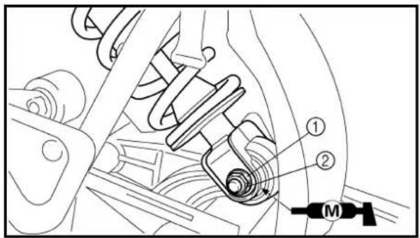
text_image
Technical diagram of a vehicle suspension system with labeled components and a motor indicatorInstallation
1. Install:
- Rear shock absorber assembly On frame.
NOTE:
Install the rear shock absorber assembly with its warning label @ facing left side of the machine.
2. Install:
- Bolt (rear shock absorber assembly - frame)
- Plain washer ①
- Nut (rear shock absorber assembly - frame) ②
53 Nm (5.3 m · kg, 38 ft · lb)
NOTE: \_\_\_\_
Apply the molybdenum disulfide grease on the bolt (rear shock absorber assembly - frame).
3. Install:
- Bolt (rear shock absorber assembly - relay arm)
- Plain washer ①
- Nut (rear shock absorber assembly - relay arm) ②
35 Nm (3.5 m · kg, 25 ft · lb)
NOTE:
Apply the molybdenum disulfide grease on the bolt (rear shock absorber assembly - relay arm).
COMBINÉ RESSORT-AMORTISSEUR ARRIÈRE HINTERRAD-STOSSDÄMPFER
Installation
1. Installer:
① CDI unit
② Engine stop switch
③ Ignition coil
④ CDI magneto
⑤ Spark plug
COLOR CODE
| B | Black |
| Br | Brown |
| G | Green |
| O | Orange |
| R | Red |
| W | White |
| B/R | Black/Red |
| B/W | Black/White |
| G/L | Green/Blue |
| G/W | Green/White |
| W/L | White/Blue |
| W/R | White/Red |
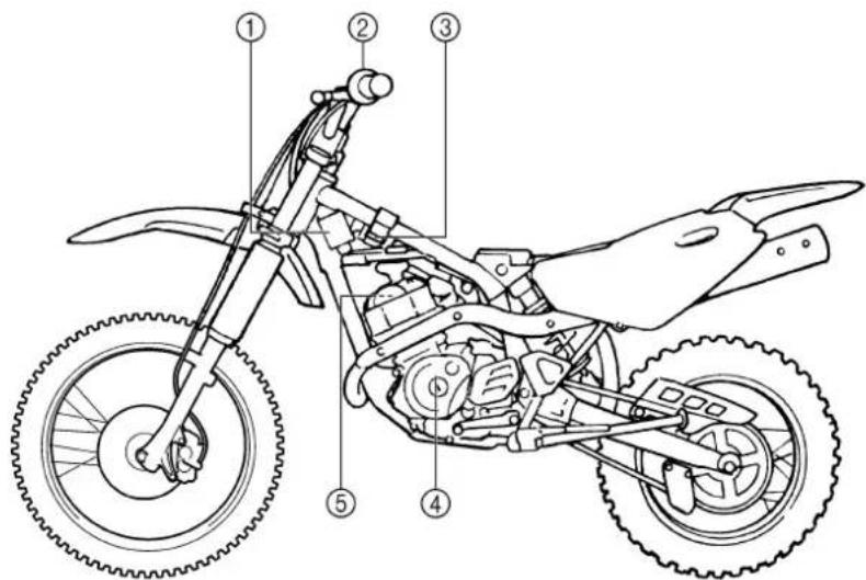
text_image
Technical diagram of a four-wheeled motorcycle with numbered parts labeled for identification.* The illustration shows the TT-R125LW
EC612000
WIRING DIAGRAM

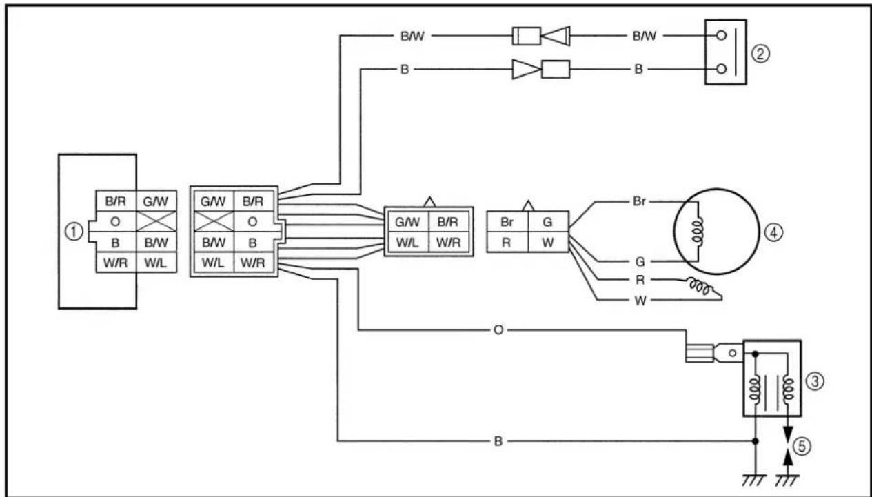
flowchart
graph TD
    A["①"] --> B["B/R G/W"]
    A --> C["O B W/L"]
    A --> D["G/W B/R"]
    A --> E["O B/W L W/R"]
    B --> F["B/W"]
    C --> G["B/W"]
    D --> H["G/W B/R W/L W/R"]
    E --> I["G/W B/R W/L W/R"]
    F --> J["Br R G W"]
    G --> K["Br R W"]
    H --> L["Br R W"]
    I --> M["Br R W"]
    J --> N["②"]
    K --> O["③"]
    L --> P["④"]
    M --> Q["⑤"]
    N --> R["Ground"]
    O --> S["Ground"]
    P --> T["Ground"]
PARTIE ÉLECTRIQUE ÉQUIPEMENT ÉLECTRIQUE ET SCHÉMA DE CÂBLAGE COMPOSANTS ÉLECTRIQUES
Use the following steps for checking the possibility of the malfunctioning engine being attributable to ignition system failure and for checking the spark plug which will not spark.
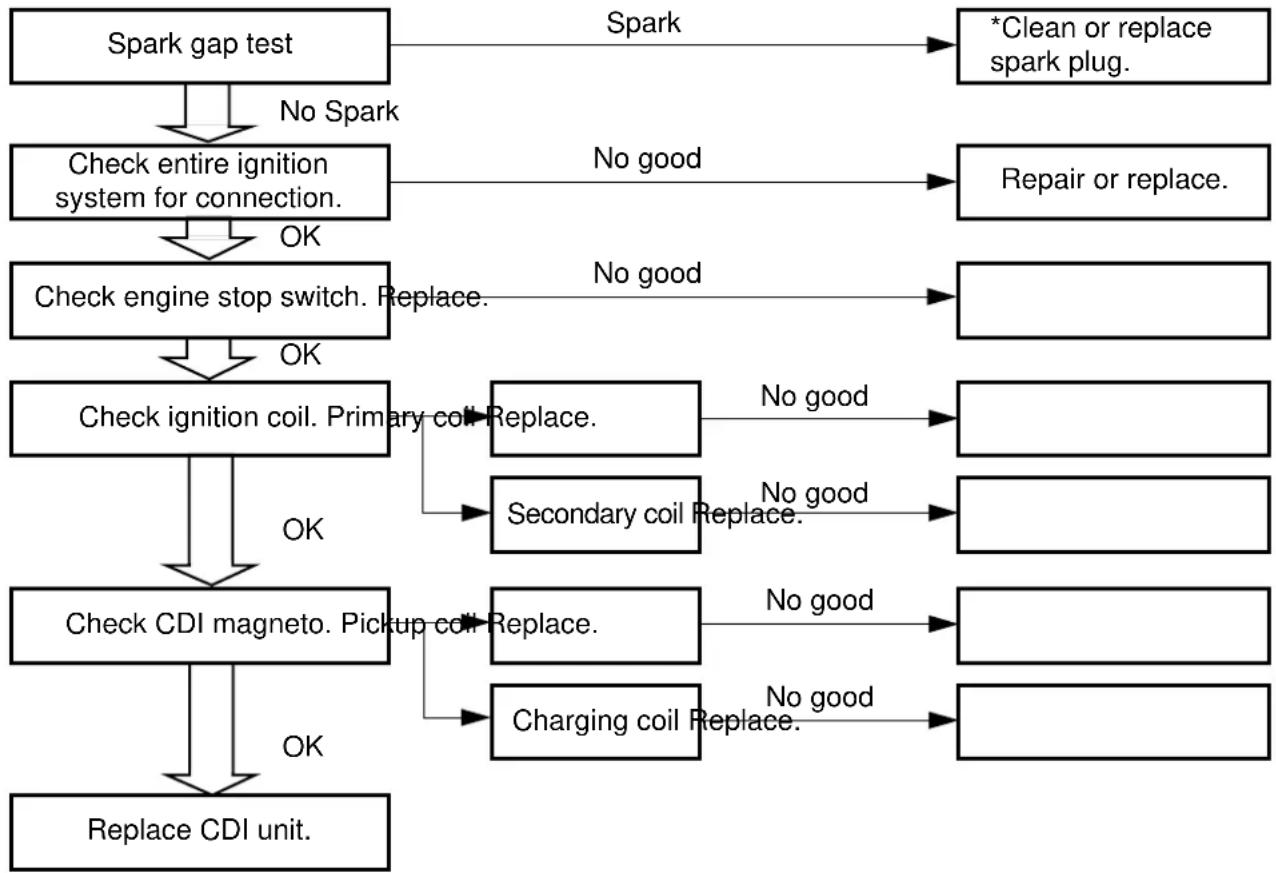
flowchart
graph TD
    A["Spark gap test"] -->|No Spark| B["Check entire ignition system for connection."]
    B -->|OK| C["Check engine stop switch. Replace."]
    C -->|OK| D["Check ignition coil. Primary coil Replace."]
    D -->|No good| E["Secondary coil Replace."]
    D -->|No good| F["Charging coil Replace."]
    E --> G["Check CDI magneto. Pickup coil Replace."]
    F --> H["Charging coil Replace."]
    G --> I["Replace CDI unit."]
    H --> I
    J["*Clean or replace spark plug."] --> K["Spark"]
    L["Repair or replace."] --> M["No good"]
    N[" "] --> O["No good"]
    P[" "] --> Q["No good"]
    R[" "] --> S["No good"]
*marked: Only when the ignition checker is used.
NOTE:
- Remove the following parts before inspection.
1) Seat
2) Fuel tank - Use the following special tools in this inspection.
Dynamic spark tester: YM-34487
Ignition checker: 90890-06754
Pocket tester: YU-3112-C/90890-03112
SYSTÈME D'ALLUMAGE
ÉTAPES DU CONTRÔLE
- Disconnect the spark plug cap from spark plug.
-
Connect the dynamic spark tester ① (ignition checker ②) as shown.
-
Spark plug cap ③
- Spark plug ④
A For USA and CDN
B Except for USA and CDN
- Kick the kickstarter crank.
- Check the ignition spark gap.
- Start engine, and increase spark gap until misfire occurs. (for USA and CDN only)

Minimum spark gap: 6.0 mm (0.24 in)
EC624000
COUPLERS AND LEADS CONNECTION INSPECTION
- Check:
- Couplers and leads connection Rust/dust/looseness/short-circuit → Repair or replace.
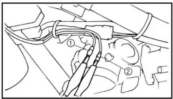
text_image
Technical diagram showing wiring connections with numbered annotations indicating parts of a vehicle or connector assembly.ENGINE STOP SWITCH INSPECTION
- Inspect:
• Engine stop switch conduct.
| Tester (+) lead → Black/White lead 1 |
| Tester (−) lead → Black lead 2 |
| B/W1 | B2 | Tester selec-tor position | ||
| PUSH IN | ○ | ○ | Ω·1 | |
| FREE |
Not continuous while being pushed → Replace.
Continuous while being freed → Replace.
TEST DE LA LONGUEUR D'ÉTINCELLE
text_image
Technical diagram showing mechanical assembly with labeled parts ① and ②, likely illustrating a linkage or mounting mechanism.EC626002
IGNITION COIL INSPECTION
1. Inspect:
- Primary coil resistance Out of specification → Replace.
| Tester (+) lead → Orange lead 1 |
| Tester (−) lead → Black lead 2 |
| Primary coil resistance | Tester selector position | |
| 0.18 ~ 0.28 Ω at 20 °C (68 °F) | Ω · 1 |
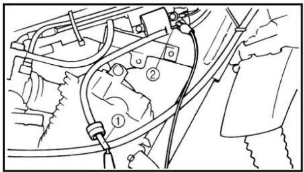
text_image
Technical diagram showing car engine components with numbered labels indicating parts of the engine and wiring.2. Inspect:
• Secondary coil resistance Out of specification → Replace.
| Tester (+) lead → Spark plug lead 1 |
| Tester (−) lead → Orange lead 2 |
| Secondary coil resistance | Tester selector position | |
| 6.3 ~ 9.5 kΩ at 20 °C (68 °F) | kΩ · 1 |
NOTE:
When inspecting the secondary coil resistance, remove the spark plug cap.
CONTRÔLE DE LA BOBINE D'ALLUMAGE
1. Examiner:
text_image
Br G R W ① ②CDI MAGNETO INSPECTION
1. Inspect:
- Pickup coil resistance Out of specification → Replace.
| Tester (+) lead → Red lead 1 |
| Tester (−) lead → White lead 2 |
| Pickup coil resistance | Tester selector position | |
| 248 ~ 372 Ω at 20 °C (68 °F) | Ω · 100 |
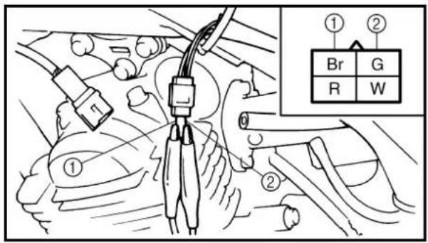
text_image
Technical diagram showing car engine wiring connections with labeled components and a color-coded legend for electrical symbols.2. Inspect:
- Charging coil resistance Out of specification → Replace.
| Tester (+) lead → Brown lead 1 |
| Tester (−) lead → Green lead 2 |
| Charging coil resistance | Tester selector position | |
| 688 ~ 1,032 Ω at 20 °C (68 °F) | Ω · 100 |
EC628000
CDI UNIT INSPECTION
Check all electrical components. If no fault is found, replace the CDI unit. Then check the electrical components again.