
RX-F31S - AV receiver JVC - Free user manual and instructions
Find the device manual for free RX-F31S JVC in PDF.
| Product type | Audio-video receiver (Home Cinema Control Center) |
| Brand | JVC |
| Model | RX-F31S |
| Dimensions (W × H × D) | 435 mm × 70 mm × 317.2 mm |
| Weight | 6.3 kg |
| Power supply | AC 230 V ~ 50 Hz |
| Power consumption | 110 W operating, 2 W standby |
| Output power | 5 × 100 W (6 Ω, 1 kHz, 0.8% THD) |
| Speaker impedance | 6 Ω - 16 Ω |
| Audio inputs | Analog (RCA): TV, VCR, DVR/DVD, VIDEO, DVD MULTI; Digital: 1 coaxial, 2 optical |
| Video inputs | Composite (RCA), S-Video, Component (Y, Pb, Pr), RGB (SCART) |
| Outputs | Speakers (5 channels), Subwoofer (RCA), Monitor (component, SCART), Headphones (6.35mm jack) |
| SCART connectors | 3 (TV, VCR, DVR/DVD) with T-V LINK compatibility |
| Radio | FM (87.50 - 108.00 MHz) and AM (522 - 1629 kHz) with RDS |
| Digital audio formats | Dolby Digital, DTS, DTS 96/24, LPCM (32/44.1/48 kHz) |
| Surround modes | Dolby Pro Logic II, DTS-ES, Virtual Surround Back, DSP (Hall, Live Club, etc.) |
| Special functions | Smart Surround Setup, TV Direct, Midnight Mode, Sleep Timer, LFE Attenuator |
| Remote control | Infrared, programmable for TV, VCR, STB and other JVC products |
| Display | Fluorescent tube display with dimmer |
| Safety | Side ventilation (10 cm), rear (15 cm), do not block vents |
| Maintenance | Clean with a dry, soft cloth; do not use liquid products |
| Country of origin | Japan (JVC) |
Frequently Asked Questions - RX-F31S JVC
User questions about RX-F31S JVC
0 question about this device. Answer the ones you know or ask your own.
Ask a new question about this device
Download the instructions for your AV receiver in PDF format for free! Find your manual RX-F31S - JVC and take your electronic device back in hand. On this page are published all the documents necessary for the use of your device. RX-F31S by JVC.
USER MANUAL RX-F31S JVC
HOME CINEMA CONTROL CENTER
RX-F31S


INSTRUCTIONS
IMPORTANT for the U.K.
DO NOT cut off the mains plug from this equipment. If the plug fitted is not suitable for the power points in your home or the cable is too short to reach a power point, then obtain an appropriate safety approved extension lead or consult your dealer.
BE SURE to replace the fuse only with an identical approved type, as originally fitted.
If nonetheless the mains plug is cut off ensure to remove the fuse and dispose of the plug immediately, to avoid a possible shock hazard by inadvertent connection to the mains supply.
If this product is not supplied fitted with a mains plug then follow the instructions given below:
IMPORTANT:
DO NOT make any connection to the terminal which is marked with the letter E or by the safety earth symbol or coloured green or green-and-yellow.
The wires in the mains lead on this product are coloured in accordance with the following code:
Blue: Neutral
Brown:Live
As these colours may not correspond with the coloured markings identifying the terminals in your plug proceed as follows:
The wire which is coloured blue must be connected to the terminal which is marked with the letter N or coloured black.
The wire which is coloured brown must be connected to the terminal which is marked with the letter L or coloured red.
IF IN DOUBT - CONSULT A COMPETENT ELECTRICIAN.
Caution—/I STANDBY/ON button!
Disconnect the mains plug to shut the power off completely. The / STANDBY/ON button in any position does not disconnect the mains line. The power can be remote controlled.
CAUTION
To reduce the risk of electrical shocks, fire, etc.:
- Do not remove screws, covers or cabinet.
- Do not expose this appliance to rain or moisture.
CAUTION
- Do not block the ventilation openings or holes. (If the ventilation openings or holes are blocked by a newspaper or cloth, etc., the heat may not be able to get out.)
- Do not place any naked flame sources, such as lighted candles, on the apparatus.
- When discarding batteries, environmental problems must be considered and local rules or laws governing the disposal of these batteries must be followed strictly.
- Do not expose this apparatus to rain, moisture, dripping or splashing and that no objects filled with liquids such as vases, shall be placed on the apparatus.
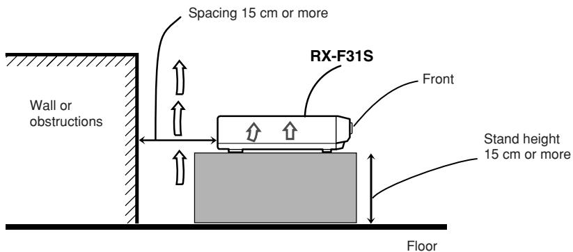
Caution: Proper Ventilation
To avoid risk of electric shock and fire and to protect from damage.
Locate the apparatus as follows:
Front: No obstructions open spacing.
Sides: No obstructions in 10cm from the sides.
Back: No obstructions in 15cm from the back.
Bottom: No obstructions, place on the level surface.
In addition, maintain the best possible air circulation as illustrated.
SAFETY INSTRUCTIONS "SOME DOS AND DON'TS ON THE SAFE USE OF EQUIPMENT"
This equipment has been designed and manufactured to meet international safety standards but, like any electrical equipment, care must be taken if you are to obtain the best results and safety is to be assured.

Do read the operating instructions before you attempt to use the equipment.
Do ensure that all electrical connections (including the mains plug, extension leads and interconnections between pieces of equipment) are properly made and in accordance with the manufacturer's instructions. Switch off and withdraw the mains plug when making or changing connections.
Do consult your dealer if you are ever in doubt about the installation, operation or safety of your equipment.
Do be careful with glass panels or doors on equipment.

DON'T continue to operate the equipment if you are in any doubt about it working normally, or if it is damaged in any way—switch off, withdraw the mains plug and consult your dealer.
DON'T remove any fixed cover as this may expose dangerous voltages.
DON'T leave equipment switched on when it is unattended unless it is specifically stated that it is designed for unattended operation or has a standby mode.
Switch off using the switch on the equipment and make sure that your family know how to do this.
Special arrangements may need to be made for infirm or handicapped people.
DON'T use equipment such as personal stereos or radios so that you are distracted from the requirements of traffic safety. It is illegal to watch television whilst driving.
DON'T listen to headphones at high volume as such use can permanently damage your hearing.
DON'T obstruct the ventilation of the equipment, for example with curtains or soft furnishings.
Overheating will cause damage and shorten the life of the equipment.
DON'T use makeshift stands and NEVER fix legs with wood screws—to ensure complete safety always fit the manufacturer's approved stand or legs with the fixings provided according to the instructions.
DON'T allow electrical equipment to be exposed to rain or moisture.
ABOVE ALL
NEVER let anyone, especially children, push anything into holes, slots or any other opening in the case—this could result in a fatal electrical shock.;
NEVER guess or take chances with electrical equipment of any kind—it is better to be safe than sorry!
Parts identification 2
Getting started 4
Before Installation 4
Checking the supplied accessories 4
Putting batteries in the remote control 4
Connecting the FM and AM (MW) antennas 5
Connecting the speakers 6
Connecting video components 7
Connecting the power cord 11
Basic operations 12
1 Turn on the power 12
2 Select the source to play 12
3 Adjust the volume 13
Selecting the digital decode mode 13
Adjusting the subwoofer audio position 14
Activating TV Direct 14
Turning off the sounds temporarily 15
Changing the display brightness 15
Turning off the power with the Sleep Timer 15
Basic settings 16
Setting the speaker information automatically —Smart Surround Setup 16
Basic setting items 18
Operation through on-screen display menus 18
Menu operation buttons 18
Setup menu configuration 19
Menu operating procedure 20
Setting the items 21
Setting the speakers 21
Setting the virtual surround back speaker —VIRTUAL SURROUND BACK 22
Selecting the main or sub channel-DUAL MONO 22
Setting bass sound 23
Using the Midnight mode—MIDNIGHT MODE 23
Setting the digital input (DIGITAL IN) terminals
—DIGITAL IN 1/2/3 24
Setting the Auto Function mode-AUTO MODE 24
Selecting the type of the input signal DVDVIDEOINPUT/VCRVIDEOINPUT 25
Superimposing the menus—SUPERIMPOSE 25
Converting S-video signals into composite video signals DOWN MIX 25
Converting composite video signals into S-video signals —Y/C SEPARATE 25
Sound adjustments 26
Basic adjustment items 26
Operation through on-screen display menus 26
Menu operation buttons 26
Setup menu configuration 27
Menu operating procedure 28
Adjusting the items 29
Adjusting speaker output level 29
Adjusting the equalization patterns —DIGITAL EQ 63Hz/250Hz/1kHz/4kHz/16kHz ………… 30
Adjusting the bass sounds 30
Adjusting the sound parameters for the Surround/DSP modes 31
Tuner operations 32
Tuning in to stations manually 32
Using preset tuning 32
Selecting the FM reception mode 33
Using the Radio Data System (RDS) to receive FM stations 34
Searching for a program by PTY codes 35
Switching to broadcast program of your choice temporarily 37
Creating realistic sound fields 38
Reproducing theatre ambience 38
Introducing the Surround modes 38
Introducing the DSP modes 40
Activating the Surround/DSP modes 41
Operating other JVC products 44
Operating other manufacturers' products 46
Troubleshooting 49
Specifications 50
Parts identification
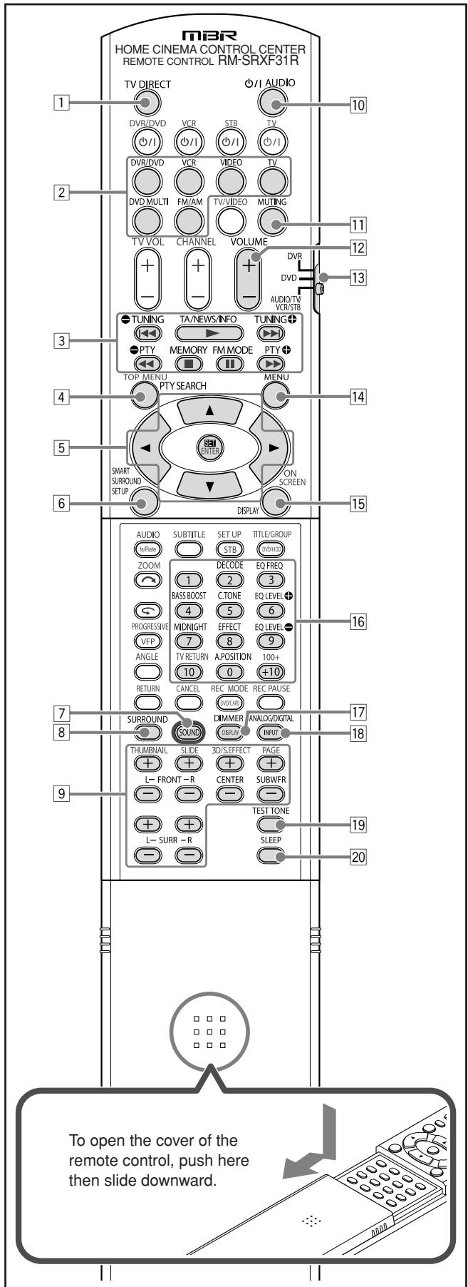
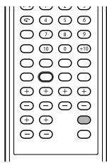
Remote control
See pages in parentheses for details.
TV DIRECT button (7, 14, 24)
Source selecting buttons (12, 14, 32 - 34) DVR/DVD, VCR, VIDEO, TV, DVD MULTI, FM/AM
3 ·Operating buttons for tuner (32, 33)
TUNING, TUNING , MEMORY, FM MODE
- Operating buttons for RDS (35, 37)
TA/NEWS/INFO, PTY, PTY
4 PTY SEARCH button (35)
[5] On-screen display operation buttons (18, 26)
Cursor buttons ( , , ,)
SMART SURROUND SETUP button (16)
7 SOUND button (13, 14, 23, 30, 31)
8 SURROUND button (42)
Adjusting buttons for speaker and subwoofer output levels (29) FRONT L + / - ,FRONT R + / - ,CENTER + / - ,SUBWFR + / - , SURL + / - ,SURR R + / -
10 0/IAUDIO button (12,14)
11 MUTING button (15)
12 VOLUME + / - button (13)
13 Mode selector (12, 14, 16, 18, 23, 26, 29 - 32, 34, 42)
DVR, DVD, AUDIO/TV/VCR/STB
14 MENU button (18, 26)
15 DISPLAY button (34)
Numeric buttons (33)
- Adjusting buttons (13, 14, 23, 30, 31)
- DECODE, EQ FREQ, BASS BOOST, C.TONE, EQ LEVEL , MIDNIGHT, EFFECT, EQ LEVEL , A.POPOSITION
DIMMER button (15)
18 ANALOG/DIGITAL INPUT button (12)
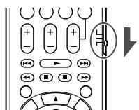
TEST TONE button (17, 29)
20 SLEEP button (15)
The buttons which are not indicated here can be used for operating other JVC products or other manufacturers' products. For details, see pages 44 to 48.
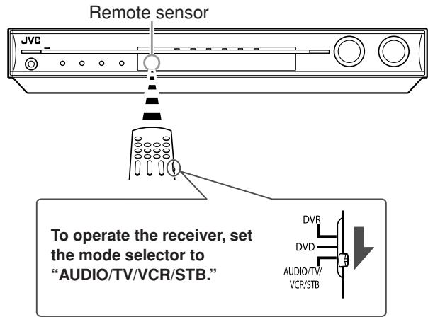
- When operating this receiver, set the mode selector (13) to "AUDIO/TV/VCR/STB."
- When operating a JVC DVD recorder, set the mode selector (13) to "DVR."
- When operating a JVC DVD player, set the mode selector (13) to "DVD."
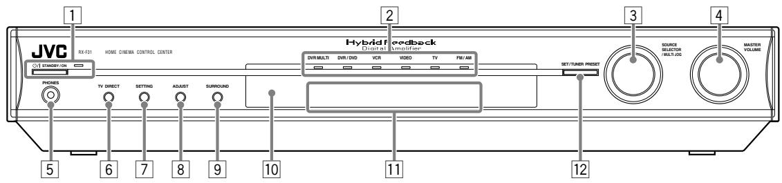
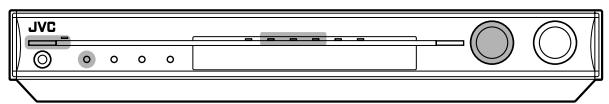
Front panel
1 O/ISTANDBY/ON button and standby lamp (12, 14)
2 Source lamps
DVD MULTI, DVR/DVD, VCR,VIDEO, TV, FM/AM
3 SOURCE SELECTOR (12, 14, 33)
- MULTI JOG (18, 26, 33, 42)
4 MASTER VOLUME control (13)
5 PHONES jack (13)
6 TV DIRECT button (14)
7 SETTING button (18)
ADJUST button (26)
9 SURROUND button (42)
Remote sensor (4)
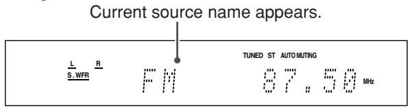
Display window (see below)
12 SET button (17, 18, 26)
TUNER PRESET button (33)
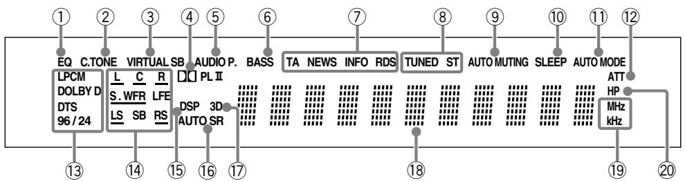
Display window
① EQ indicator (30)
② C.TONE indicator (31)
③ VIRTUAL SB indicator (22, 38, 39)
④ DPLI indicator (39, 40)
⑤ AUDIO P. (position) indicator (14)
⑥ BASSindicator(30)
⑦ RDS operation indicators (34, 37) TA, NEWS, INFO, RDS
8 Tuner operation indicators (32) TUNED, ST (stereo)
9 AUTO MUTING indicator (33)
SLEEP indicator (15)
1 AUTO MODE indicator (24)
12 ATT (attenuator) indicator (30)
^13 Digital signal format indicators (13, 38, 39) LPCM (Linear PCM), DOLBY D (Dolby Digital), DTS, 96/24
14 Signal and speaker indicators (15)
15 DSP indicator (39, 40, 41)
16 AUTO SR (surround) indicator (43)
⑰ 3D indicator (39, 40, 41)
18 Main display
Frequency unit indicators MHz (for FM station), kHz (for AM (MW) station)
HP (headphones) indicator (13, 39, 41)
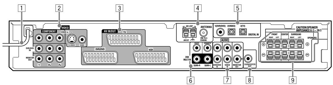
Rear panel
Power cord (11)
VIDEO terminals (8-10)
- COMPONENT (Y, PB, PR):
VIDEO IN, DVR/DVD IN, MONITOR OUT
S-VIDEO
VIDEO IN
VIDEO (composite video)
VIDEO IN
3 AV IN/OUT terminals (7) TV, DVR/DVD, VCR
4 ANTENNA terminals (5)
5 DIGITAL IN terminals (11)
Coaxial: 1(DVR/DVD)
Optical: 2(VIDEO), 3(TV)
DVD MULTI IN jacks (9)
CENTER, SUBWOOFER, SURR-R, SURR-L
7 AUDIO jacks (8-10)
DVR/DVD IN,VIDEO IN,MONITOR OUT
SUBWOOFER OUT jack (6)
9 SPEAKERS terminals (6)
FRONT, CENTER, SURROUND
Getting started
Before Installation
General precautions
- Be sure your hands are dry.
- Turn the power off to all components.
- Read the manuals supplied with the components you are going to connect.
Locations
- Install the receiver in a location that is level and protected from moisture and dust.
- The temperature around the receiver must be between -5^ and 35^ .
- Make sure there is good ventilation around the receiver. Poor ventilation could cause overheating and damage the receiver.
- Leave sufficient distance between the receiver and the TV.
Handling the receiver
- Do not insert any metal object into the receiver.
- Do not disassemble the receiver or remove screws, covers, or cabinet.
- Do not expose the receiver to rain or moisture.
- Do not pull on the power cord to unplug the cord. When unplugging the cord, always grasp the plug so as not to damage the cord.
- When you are away on travel or otherwise for an extended period or time, remove the plug from the wall outlet. A small amount of power is always consumed while the power cord is connected to the wall outlet.
The receiver has a built-in cooling fan which operates while the receiver is turned on. Be sure to leave enough ventilation to obtain sufficient cooling effect.
CAUTION:
Do not connect the AC power plug to the wall outlet until all connections are completed.
Checking the supplied accessories
Check to be sure you have all of the following supplied accessories. If anything is missing, contact your dealer immediately.
- Remote control (× 1)
- Batteries (×2)
- AM (MW) loop antenna (× 1)
FM antenna (× 1) - SCART cable (× 1)
- Digital coaxial cable (× 1)
Putting batteries in the remote control
Before using the remote control, put two supplied batteries first.
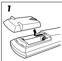
1 Press and slide the battery cover on the back of the remote control.
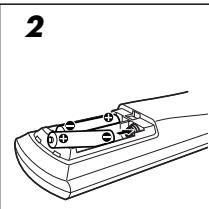
2 Insert batteries.
Make sure to match the polarity: (+) to (+) and (-) to (-) .
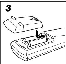
3 Replace the cover.
If the range or effectiveness of the remote control decreases, replace the batteries. Use two R6(SUM-3)/AA(15F) type dry-cell batteries.
- Supplied butterflies are for initial setup. Replace for continued use.
CAUTION:
Follow these precautions to avoid leaking or cracking cells:
- Place batteries in the remote control so they match the polarity: (+) to (+) and (-) to (-).
- Use the correct type of batteries. Batteries that look similar may differ in voltage.
Always replace both batteries at the same time.
- Do not expose batteries to heat or flame.
When using the remote control, aim the remote control directly at the remote sensor on the front panel.
Connecting the FM and AM (MW) antennas
Do not connect the AC power plug to the wall outlet until all connections are completed.
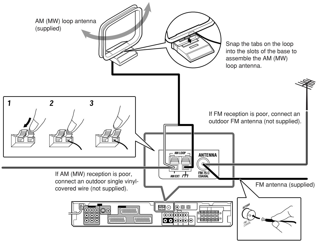
AM (MW) antenna connection
Connect the AM (MW) loop antenna supplied to the AM LOOP terminals.
Connect the white cord to the AM EXT terminal, and connect the black cord to the _7 terminal.
Turn the loop until you have the best reception.
- If the reception is poor, connect an outdoor single vinyl-covered wire (not supplied) to the AM EXT terminal. Keep the AM (MW) loop antenna connected.
FM antenna connection
Connect the FM antenna supplied to the FM 75 Ω COAXIAL terminal as a temporary measure.
Extend the supplied FM antenna horizontally.
- If the reception is poor, connect an outdoor FM antenna (not supplied). Before attaching a 75 coaxial cable with a connector (IEC or DIN 45325), disconnect the supplied FM antenna.
NOTES
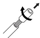
- If the AM (MW) loop antenna wire is covered with vinyl, remove the vinyl while twisting it as shown on the right.
- Make sure the antenna conductors do not touch any other terminals, connecting cords and power cord. This could cause poor reception.
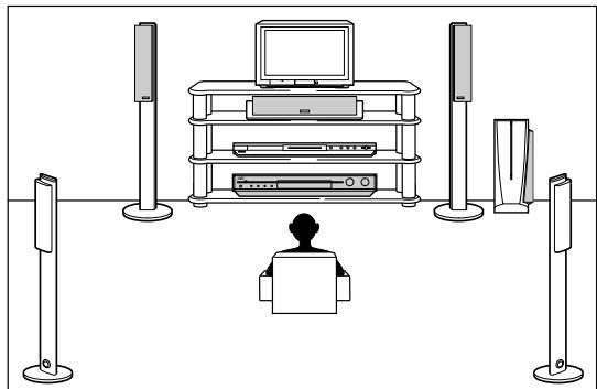
Connecting the speakers
Do not connect the AC power plug to the wall outlet until all connections are completed.
Speaker Layout Diagram
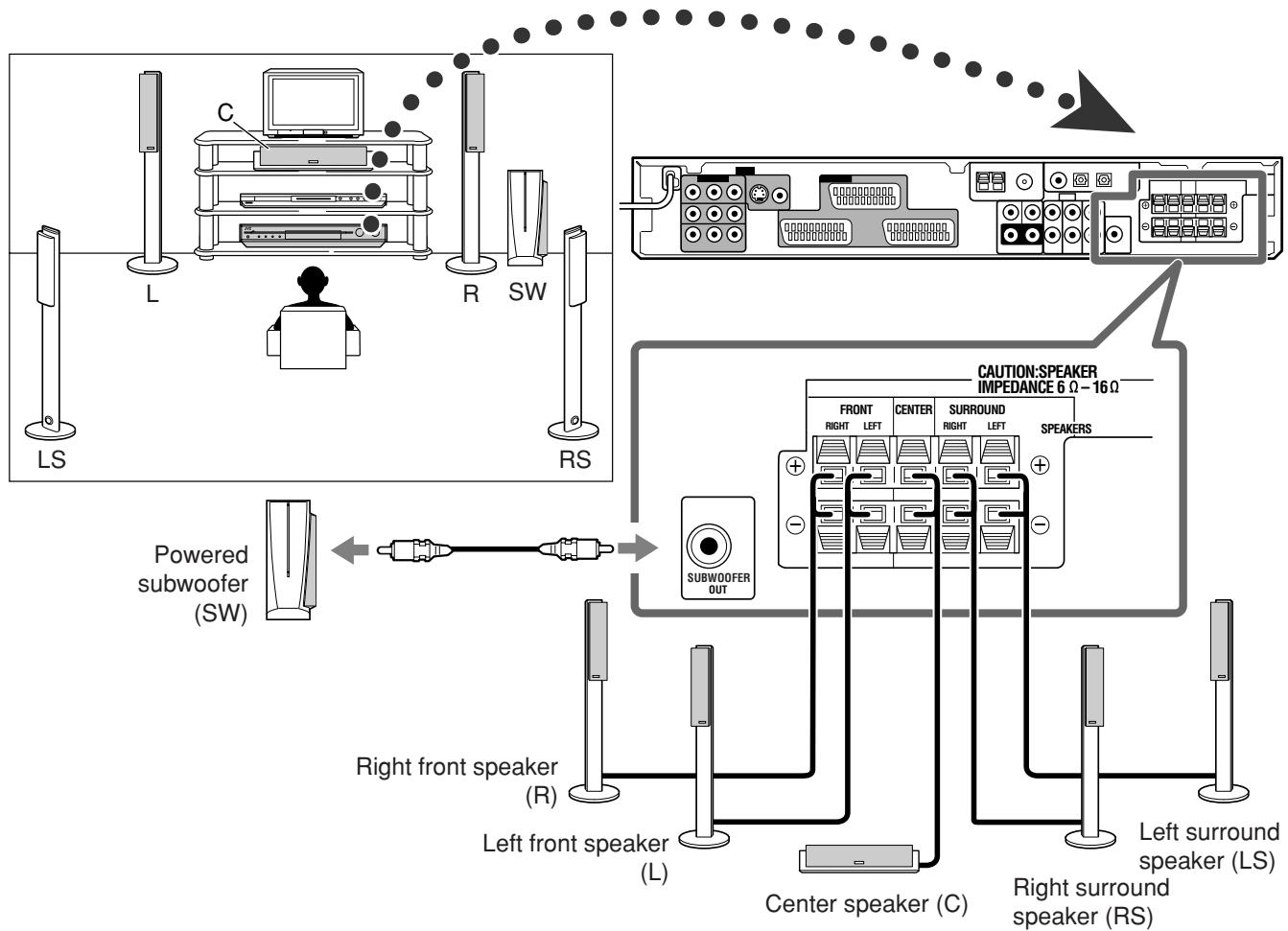
Connecting the speakers
Turn off all components before making connections.
1
2
3
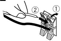
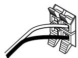
1 Twist and remove the insulation at the end of each speaker cord.
2 Press and hold the clamp of the speaker terminal (①), then insert the speaker cord (②).
- For each speaker, connect the (+) and (-) terminals on the rear panel to the (+) and (-) terminals marked on the speakers.
3 Release the finger from the clamp.
CAUTIONS:
- Use speakers with the SPEAKER IMPEDANCE indicated by the speaker terminals (6 Ω - 16 Ω).
- DO NOT connect more than one speaker to one speaker terminal.
Connecting the powered subwoofer
By connecting a subwoofer, you can enhance the bass or reproduce the original LFE signals recorded in digital software.
Connect the input jack of a powered subwoofer to the SUBWOOFER OUT jack on the rear panel, using a cord with RCA pin plugs (not supplied).
Refer also to the manual supplied with your subwoofer.
After connecting all the speakers and/or a subwoofer, set the speaker setting information properly to obtain the best possible surround effect. For details, see pages 16, 17, and 21 to 23.
NOTE
You can place a subwoofer wherever you like since bass sound is non-directional. Normally place it in front of you.
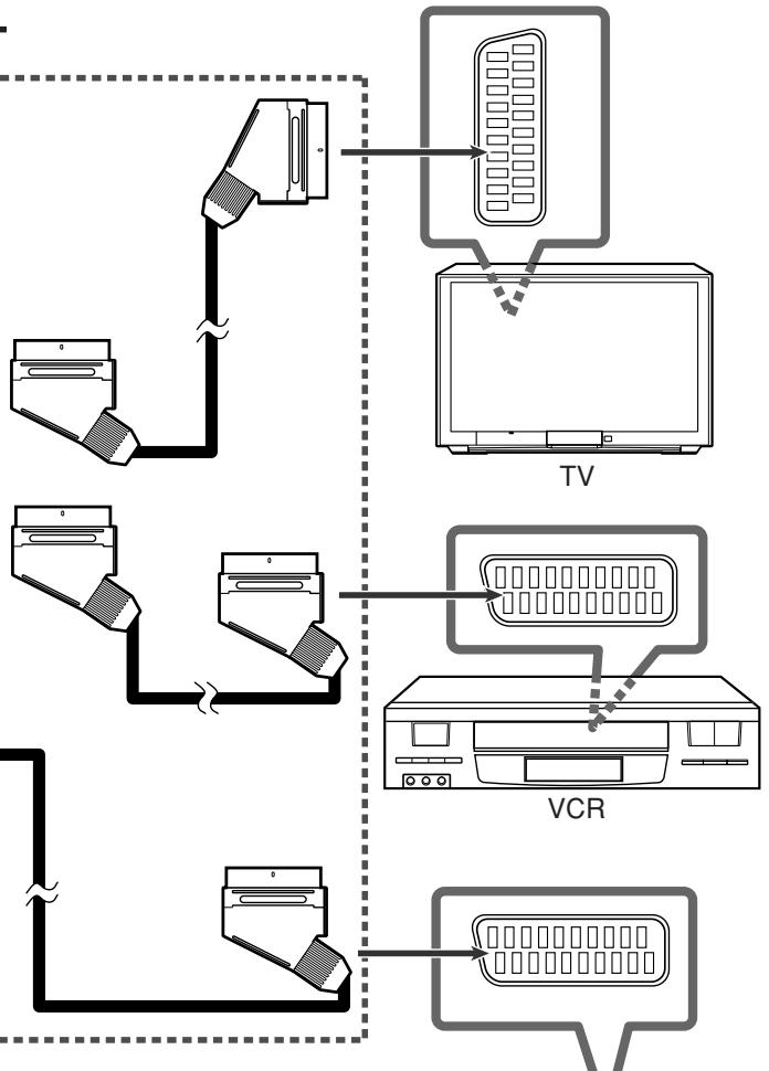
Connecting video components
SCART connection
You can enjoy pictures and sounds from playback components simply by connecting with the SCART cable.
- If your video components have digital output terminal, also connect them using the digital terminals explained in "Digital connection" (see page 11). By using these terminals, you can get better sound quality.
IMPORTANT:
Make the following adjustments correctly; otherwise, you cannot view the playback picture on the TV.
DVDVIDEOINPUTandVCRVIDEOINPUT settings
-DOWN MIX setting
-Y/C SEPARATE setting
For details about each setting, see page 25.
DO NOT use a TV through a VCR or a TV with a built-in VCR; otherwise, the picture may be distorted.
Turn off all components before making connections.
- Illustrations of the input/output terminals are typical examples. When you connect other components, refer also to their manuals since the terminal names actually printed on the rear vary among different components.
CAUTION:
If you connect a sound-enhancing device such as a graphic equalizer between the source components and this receiver, the sound output through this receiver may be distorted.
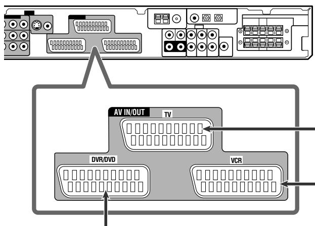
SCART cable (supplied: 1 cable)
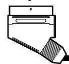
DVD recorder or DVD player
NOTE
When the TV is equipped with multiple SCART terminals, refer to the TV manual to check the available video signals for each terminal, then connect the SCART cable correctly.
SCART Terminal Specifications
Any signal input from a SCART terminal cannot be output through the same SCART terminal.
1 Composite video signals and S-video signals can be converted into each other. For details about the settings and the output of the signals, see page 25.
2 Only when TV Direct is in use (see page 14).
*3 The signals for the T-V LINK function are always going through the receiver.
For an analogue decoder
To watch through or to record a scrambled program on your VCR, connect the analogue decoder to your VCR and select the scrambled channel on your VCR. If there is not an appropriate terminal for the decoder connection on your VCR, connect the decoder to your TV.
Refer also to the manuals supplied with these components.
For T-V LINK
- You can use the T-V LINK function if you connect a T-V LINK compatible TV and VCR to this receiver with a fully wired SCART cables. For details on T-V LINK, refer also to the manuals supplied with the TV and the VCR.
- Connect a SCART cable to EXT-2 terminal on the JVC's T-V LINK compatible TV for the T-V LINK function.
- Some video components support the data communication like T-V LINK. For complete details, refer also to the manuals supplied with these components.
Audio/video connection
In addition to the SCART terminals, this receiver is equipped with the following video terminals:
- Component video input/output:VIDEO IN, DVR/DVD IN, MONITOR OUT
- Composite and S-video input:VIDEO IN
IMPORTANT:
The component video signals from the COMPONENT jacks are transmitted only through the MONITOR OUT jacks. Therefore, if the TV is connected to the receiver through the SCART terminal (TV) and a playing video component is connected to the receiver through the component video jacks (VIDEO IN or DVR/DVD IN), you cannot view the playback picture on the TV.
- Connecting a DVD recorder or DVD player to the DVR/DVD IN jacks
To fully enjoy Dolby Digital and DTS multi-channel software (including Dual Mono software), connect the DVD recorder or DVD player through the digital input terminals (see page 11).
When you connect a DVD recorder or DVD player with its stereo output jacks:
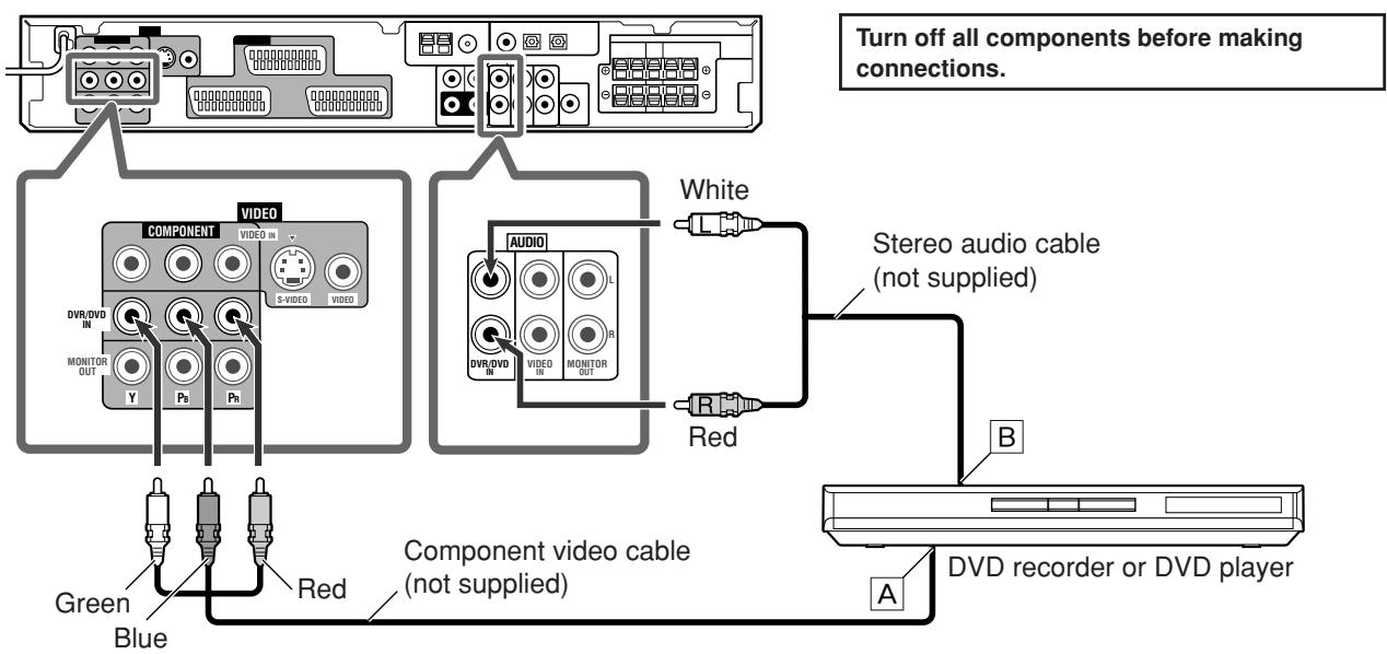
A To component video output
B To left/right audio channel output
NOTES
- Connect Y, Pb, and PR correctly.
- Do not connect different components to the AUDIO DVR/DVD IN jacks and AV IN/OUT (SCART) DVR/DVD terminal (see page 7); otherwise, sounds from both components are come out of the speakers at the same time.
When you connect a DVD player with its analogue discrete output jacks (DVD MULTI IN):
This connection is the best connection method for enjoying DVD Audio sounds. When a DVD Audio disc is played back, the original high-quality sounds can be reproduced only using this connection.
Turn off all components before making connections.
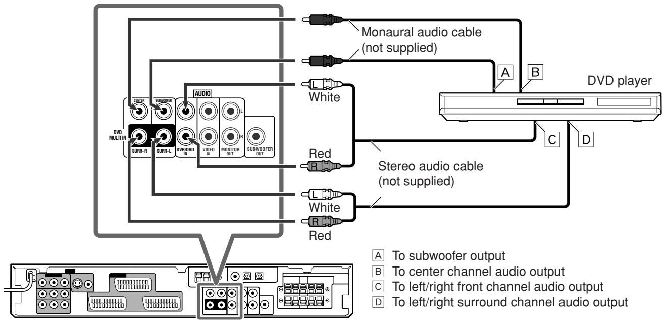
NOTE
Do not connect different components to the DVD MULTI IN jacks and AV IN/OUT (SCART) DVR/DVD terminal (see page 7); otherwise, sounds from both components are come out of the speakers at the same time.
About "DVD MULTI"
When you select "DVD MULTI" as the source (see page 12), you can enjoy analogue discrete output sound (5.1-channel reproduction) from the connected component.
- You may need to select analogue discrete output mode on the component.
NOTES
- When using the headphones, you can listen to the front channel sounds (left and right) only. (3D HEADPHONE mode is not available.)
- When TV Direct is activated while "DVD MULTI" is selected as the source, the source changes to the last selected source from among "DVR/DVD," "VCR," and "VIDEO" (see page 14).
- Surround/DSP modes (see pages 38 to 41) are not available for "DVD MULTI."
- Connecting another video component to the VIDEO IN jacks
If your video components have S-video (Y/C-separation) and/or component video (Y,PB,PR) terminals, connect them using an S-video cable (not supplied) and/or component video cable (not supplied). By using these jacks, you can get better picture quality in the order:
Component video > S-video > Composite video
To enjoy the playback from the component connected to these jacks, select "VIDEO" as the source (see page 12).
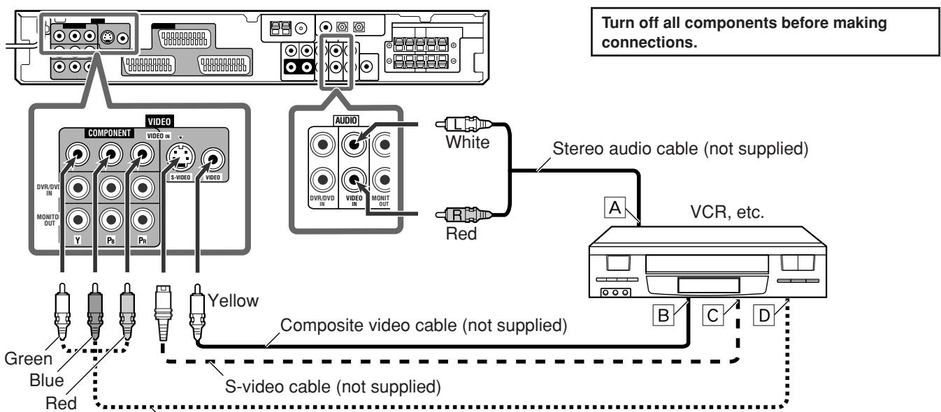
Component video cable (not supplied)
A To left/right audio channel output
To composite video output
C To S-video output
To component video output
NOTES
- Connect Y, Pb, and Pr correctly.
- The signals input from S-VIDEO and VIDEO (composite video) of VIDEO IN jacks are output through SCART terminal (see page 7).
- S-video signals and composite video signals can be converted into each other. For details, see page 25.
- Connecting a TV to the MONITOR OUT jacks
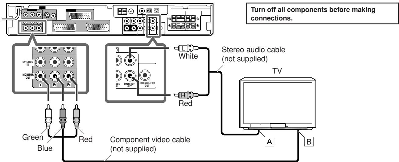
A To left/right audio channel input
To component video input
IMPORTANT:
Audio signals come out through the AUDIO MONITOR OUT (RIGHT/LEFT) jacks ONLY when TV Direct is in use (see page 14).
NOTES
- Connect Y, Pb, and Pr correctly.
- When connecting a TV through the VIDEO MONITOR OUT jacks, the on-screen display does not appear on the TV screen (see page 25).
Digital connection
This receiver is equipped with three DIGITAL IN terminals—one digital coaxial terminal and two digital optical terminals.
To reproduce the digital sound, use the digital connection in addition to the analogue connection methods described on pages 7 to 10.
Digital coaxial cable (supplied: 1 cable)

Digital optical cable (not supplied)

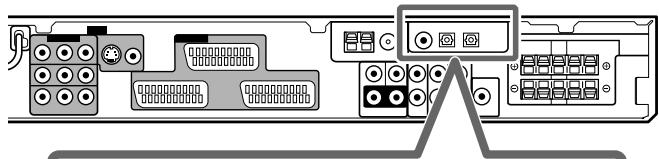
When the component has a digital coaxial output terminal, connect it to the 1(DVR/DVD) terminal, using a digital coaxial cable (supplied).
1(DVR/DVD)
2(VIDEO)
3(TV)


DIGITAL IN
When the component has a digital optical output terminal, connect it to the 2(VIDEO) or 3(TV) terminal, using a digital optical cable (not supplied).


Before connecting a digital optical cable, unplug the protective plug.
Connecting the power cord
When all the audio/video connections have been made, connect the AC power plug to the wall outlet. Make sure that the plugs are inserted firmly. The standby lamp lights in red.
CAUTIONS:
- Do not touch the power cord with wet hands.
- Do not alter, twist or pull the power cord, or put anything heavy on it, which may cause fire, electric shock, or other accidents.
- If the cord is damaged, consult a dealer and have the power cord replaced with a new one.
NOTES
- Keep the power cord away from the connecting cables and the antenna. The power cord may cause noise or screen interference.
- The preset settings such as preset channels and sound adjustment may be erased in a few days in the following cases: - When you unplug the power cord.
- When a power failure occurs.
NOTES
-
When shipped from the factory, the DIGITAL IN terminals have been set for use with the following components:
-
1(DVR/DVD): For DVD recorder or DVD player
- 2(VIDEO): For the component connected to the VIDEO IN jacks
-3(TV): For TV
If you connect other components, change the digital input (DIGITAL IN) terminal setting correctly. See "Setting the digital input (DIGITAL IN) terminals—DIGITAL IN 1/2/3" on page 24.
- Select the digital input mode. See "Selecting the analogue or digital input mode" on page 12.
Basic operations
The on-screen display appears on the TV screen for 5 seconds (except "turning off the sounds temporarily") to show the indication in the following cases:
- When you select the source (except "TV") (see right column).
- When you adjust the volume (see page 13).
- When you turn off the sounds temporarily (see page 15).
- When you select the Surround/DSP modes (see page 42).
To cancel the function, set "SUPERIMPOSE" to "SUPERIMPOSE: OFF" (see page 25).
Turn on the power
Press /1 STANDBY/ON (or /1 AUDIO on the remote control).
The standby lamp goes off and the source lamp of the current source lights in red.
To turn off the power (into standby)
Press O/ISTANDBY/ON (or O/IAUDIO on the remote control) again.
The standby lamp lights in red.
NOTE
A small amount of power is consumed in standby mode. To turn the power off completely, unplug the AC power cord.
2 Select the source to play
On the front panel:
- Turn SOURCE SELECTOR until the source name you want appears on the display.
The source lamp corresponding to the selected source lights in red.
- As you turn SOURCE SELECTOR, the source changes as follows:
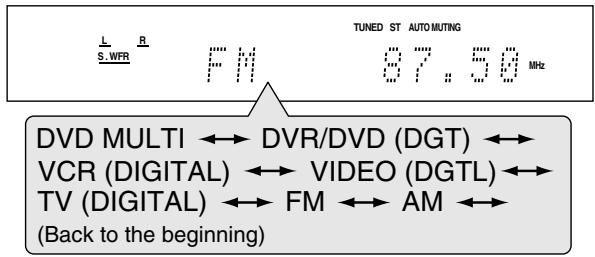
| DVD MULTI: | Select for the DVD player using the analogue discrete output mode (5.1-channel reproduction). |
| DVR/DVD (DGT)*: | Select for the DVD recorder or DVD player. |
| VCR (DIGITAL)*: | Select for the VCR. |
| VIDEO (DGTL)*: | Select for the component connected to theVIDEO IN jacks on the rear of the receiver. |
| TV (DIGITAL)*: | Select for the TV. |
| FM: | Select for an FM broadcast. |
| AM: | Select for an AM (MW) broadcast. |
From the remote control:
Press one of the source selecting buttons.
- For the tuner, press FM/AM. Each time you press FM/AM, the band alternates between “FM” and “AM.”
* Selecting the analogue or digital input mode
For a component you have connected using both the analogue connection and the digital connection methods (see pages 7 to 11), you need to select the correct input mode.
- You can select the digital input only for sources which you have selected digital input terminals for. (See "Setting the digital input (DIGITAL IN) terminals—DIGITAL IN 1/2/3" on page 24.)
From the remote control ONLY:
Press ANALOG/DIGITAL INPUT to select the analogue or digital input mode.
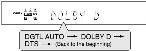
Each time you press the button, the input mode alternates between the analogue input ("ANALOGUE") and the digital input ("DGTL AUTO"). This setting is memorized for each source.
| DGTL AUTO: | Select for the digital input mode. The receiver automatically detects the incoming signal format, then the digital signal format indicator (LPCM, DOLBY D, DTS, or DTS 96/24) for the detected signal lights up. |
ANALOGUE: Select for the analogue input mode.
Initial setting: DGTL AUTO
NOTE
When you select "DVD MULTI," "FM," or "AM" as the source, the analogue and digital input mode is not available.

Adjust the volume
To increase the volume, turn MASTER VOLUME control clockwise (or press VOLUME + on the remote control).
To decrease the volume, turn MASTER VOLUME control counterclockwise (or press VOLUME - on the remote control).
- When you adjust the volume, the volume level indication appears on the display for a while.
L WFR R 20
CAUTION:
Always set the volume to the minimum before starting any sources. If the volume is set at its high level, the sudden blast of sound energy can permanently damage your hearing and/or ruin your speakers.
NOTE
The volume level can be adjusted within the range of "0" (minimum) to "50" (maximum).
Listening with headphones
You can enjoy not only stereo software but also multi-channel software through the headphones. (Sounds are down-mixed to the front channels while playing multi-channel software.)
Connect a pair of headphones to the PHONES jack on the front panel to activate the HEADPHONE mode.
The HP (headphone) indicator lights up on the display.
- You can also enjoy the Surround/DSP mode through the headphones—3D HEADPHONE mode. For details, see pages 39 and 41.
- Disconnecting a pair of headphones from the PHONES jack cancels the HEADPHONE (or 3D HEADPHONE) mode and activates the speakers.
CAUTION:
Be sure to turn down the volume:
- Before connecting or putting on headphones, as high volume can damage both the headphones and your hearing.
- Before removing headphones, as high volume may output from the speakers.
Selecting the digital decode mode
If the following symptoms occur while playing Dolby Digital or DTS software with "DGTL AUTO" selected (see page 12), follow the procedure below:
Sound does not come out at the beginning of playback.
- Noise comes out while searching for or skipping chapters or tracks.
From the remote control ONLY:
Press SOUND, then press DECODE to select "DOLBY D" or "DTS."
Each time you press DECODE, the digital decode mode changes as follows:
- To play back software encoded with Dolby Digital, select "DOLBY D."
- To play back software encoded with DTS, select "DTS."
NOTES
- When you turn off the power or select another source, "DOLBY D" or "DTS" is canceled and the digital decode mode is automatically reset to "DGTL AUTO."
- After pressing SOUND, the numeric buttons work for sound adjustments. To use the numeric buttons to operate your target source, press the corresponding source selecting button before operation; otherwise, the remote control may not work as you intend.
The following digital signal format indicators on the display indicate what type of signal comes into the receiver.
LPCM: Lights up when Linear PCM signal comes in.
DOLBY D: Lights up when Dolby Digital signal comes in.
- Flashes when "DOLBY D" is selected for any software other than Dolby Digital.
DTS: Lights up when conventional DTS signal comes in.
- Flashes when "DTS" is selected for any software other than DTS.
DTS 96/24: Lights up when DTS 96/24 signal comes in.
NOTE
When "DGTL AUTO" cannot recognize the incoming signal, no digital signal format indicator lights up on the display.

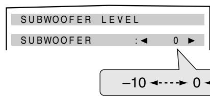
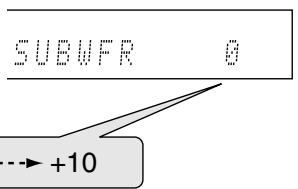
Adjusting the subwoofer audio position
If the subwoofer sound is much reinforced for stereo sound compared to the sound reproduced with multi-channel, set the subwoofer audio position. The subwoofer output level is automatically decreased by the selected value when you are listening in stereo.
The AUDIO P. indicator lights up when this function is activated.
- Once you have made an adjustment, it is memorized for each source.
From the remote control ONLY:
Press SOUND, then press A POSITION repeatedly.
Each time you press A POSITION, the subwoofer audio position level changes as follows:
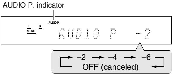
The smaller the number becomes, the more the level decreases automatically when listening in stereo.
- If no adjustment is required, select "OFF" (initial setting).
NOTES
The minimum subwoofer output level is -10dB
Ex.: When setting the subwoofer output level to -8 (dB) and the subwoofer audio position to -4 (dB), the subwoofer output level when listening in stereo will be -10 dB. To adjust the subwoofer output level, see page 29.
- This function is not available when the Surround/DSP mode is activated or "DVD MULTI" is selected.
- After pressing SOUND, the numeric buttons work for sound adjustments. To use the numeric buttons to operate your target source, press the corresponding source selecting button before operation; otherwise, the remote control may not work as you intend.
Activating TV Direct
TV Direct enables you to use this receiver as an AV selector while the receiver is turned off.
When TV Direct is activated, the pictures and sounds go from the video components such as DVD player to the TV through this receiver. Thus, you can use the video components and the TV as if they were connected directly.
- This function takes effect for the following sources—DVR/DVD, VCR, and VIDEO.
To activate (or deactivate) TV Direct, follow the procedure below:
1 Press TV DIRECT.
All the indications disappear, then the source lamp of the current source lights in green.
2 Turn on the video component and TV.
3 Select the target video component.
On the front panel:
Turn SOURCE SELECTOR until one of the source lamps—DVR/DVD, VCR, or VIDEO—lights in green.
From the remote control:
Press one of the source selecting buttons—DVR/DVD, VCR, or VIDEO.
The source lamp corresponding to the selected source lights in green.
To cancel TV Direct and turn off the receiver, press
Ø/I STANDBY/ON on the front panel (or Ø/IAUDIO on the remote control).
The receiver is turned off and the standby lamp lights up.
To cancel TV Direct and turn on the receiver, press TV DIRECT again.
The receiver is turned on and the source lamp currently selected lights in red.
NOTES
- When TV Direct is activated, you cannot enjoy any of the sound effects the receiver produces, and cannot use the speakers connected to the receiver.
- You can use the T-V LINK function between the TV and VCR while TV Direct is activated. (For T-V LINK functions, refer to the manuals supplied with the TV and the VCR.)
- When TV Direct is activated while "DVD MULTI," "FM," or "AM" is selected as the source, the source changes to the last selected source—"DVR/DVD," "VCR," or "VIDEO."
Turning off the sounds temporarily
From the remote control ONLY:
Press MUTING to turn off the sound through all connected speakers and headphones.
"MUTING" appears on the display and the volume turns off.
L R S.WFR 111111111
To restore the sound, press MUTING again.
- Pressing VOLUME +/- (or turning MASTER VOLUME control on the front panel) also restores the sound.
Changing the display brightness
You can dim the display—Dimmer.
From the remote control ONLY:
Press DIMMER repeatedly.
Each time you press the button, the display brightness changes as follows:
DIMMER 1: Dims the display slightly.
Dims the blue illumination slightly.
DIMMER 2: Dims the display more than DIMMER 1.
Dims the blue illumination slightly (more than DIMMER 1).
DIMMER 3: Turns off the display and blue illumination.
(Temporarily canceled when you operate the receiver.*)
DIMMER OFF: Cancels the Dimmer (normal display).
- Except when activating or deactivating TV Direct.
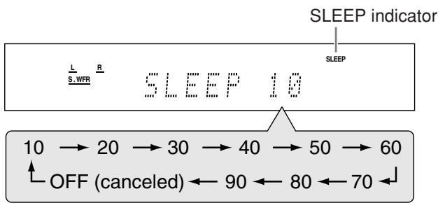
Turning off the power with the Sleep Timer
You can fall asleep while listening to music—Sleep Timer.
From the remote control ONLY:
Press SLEEP repeatedly.
Each time you press the button, the shut-off time changes in 10 minute intervals. The SLEEP indicator lights up on the display.
When the shut-off time comes:
The receiver turns off automatically.
To check or change the remaining time until the shut-off time:
Press SLEEP once.
The remaining time (in minutes) until the shut-off time appears.
- To change the shut-off time, press SLEEP repeatedly.
To cancel the Sleep Timer:
Press SLEEP repeatedly so that "SLEEP OFF" appears on the display. (The SLEEP indicator goes off.)
The Sleep Timer is also canceled when:
- You turn off the receiver, or
- TV Direct is activated.
Basic adjustment of auto memory
This receiver memorizes sound settings for each source:
- when you turn off the power, and
- when you change the source.
When you change the source, the memorized settings for the newly selected source are automatically recalled.
The following can be stored for each source:
- Analogue/digital input mode (see page 12)
- Subwoofer audio position (see page 14)
Midnight mode (see page 23) - Speaker output level (see page 29)
- Digital equalization pattern (see page 30)
- Bass boost (see page 30)
- Subwoofer phase (see page 30)
- Input attenuator mode (see page 30)
- Surround/DSP mode selection (see pages 41 to 43)
NOTE
If the source is "FM" or "AM," you can assign a different setting for each band.
Signal and speaker indicators on the display
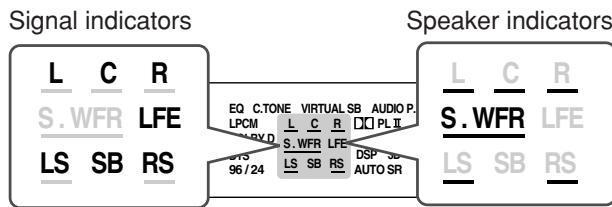
The signal indicators light up as follows:
L: When digital input is selected: Lights up when the left channel signal comes in.
- When analogue input is selected: Always lights up.
R: When digital input is selected: Lights up when the right channel signal comes in.
- When analogue input is selected: Always lights up.
C: Lights up when the center channel signal comes in.
LS: Lights up when the left surround channel signal comes in.
RS: Lights up when the right surround channel signal comes in.
SB: Lights up when the surround back channel signal comes in.
LFE: Lights up when the LFE channel signal comes in.
* When monaural surround signal comes in, only "S" lights up.
NOTE
When "DVD MULTI" is selected as the source, all the signal indicators except "SB" light up.
The speaker indicators light up as follows:
- The subwoofer indicator (S.WFR) lights up when "SUBWOOFER" is set to "SUBWOOFER: YES." For details, see page 21.
- The other speaker indicators light up only when the corresponding speaker is set to "SMALL" or "LARGE," and also when required for the current playback.
Basic settings
To obtain the best possible sound effect from Surround/DSP modes (see pages 38 to 43), you need to set up the speaker and subwoofer information after all the connections are completed. From pages 16 to 25, how to set speakers and other basic items of the receiver are explained.
Setting the speaker information automatically—Smart Surround Setup
The distance from your listening point to the speakers is one of the important elements to obtain the best possible sound effect from the Surround/DSP modes.
By using Smart Surround Setup, the following are automatically calculated by one simple action—clapping hands.
- Speaker distance (compared to that of the closest speaker)
- Speaker output level (except the subwoofer)
NOTES
- Before starting Smart Surround Setup, set the speaker information correctly (SMALL, LARGE, or NO) according to your speakers except the subwoofer (see page 21).
- When the setting is made by Smart Surround Setup, the speaker distance and output level you have set before will be inactive.
- You can see the setting process on the TV screen and the display during Smart Surround Setup. If you have turned off the display, cancel the Dimmer (see page 15); otherwise, you cannot see the information on the display.
- Smart Surround Setup will not be done correctly if you or other object blocks the sound.
- When you change your speakers, do the following procedure again.
In this section, the on-screen display on the TV screen is used for explaining.
-
The on-screen display does not appear on the TV screen in the following cases:
-
When connecting the TV through the VIDEO MONITOR OUT jacks (see page 10).
- When selecting "TV" as the source.
- When the output signals are RGB.
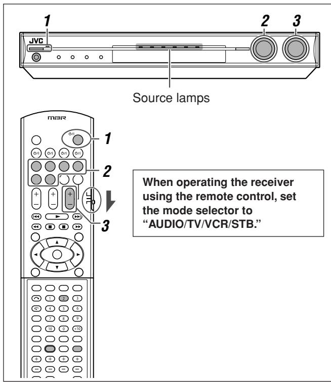
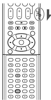
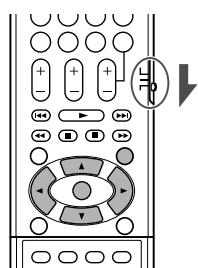
From the remote control ONLY:
When operating the receiver using the remote control, set the mode selector to "AUDIO/TV/VCR/STB."
1 Take your position where you listen to the sound.
- Make sure speaker cables are connected firmly.
2 Press and hold SMART SURROUND SETUP until "SETTING UP" flashes.
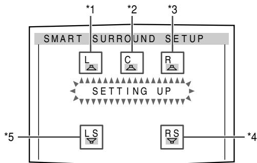
1 L: Left front speaker
2 C: Center speaker
3 R: Right front speaker
4 RS: Right surround speaker
*5 LS: Left surround speaker
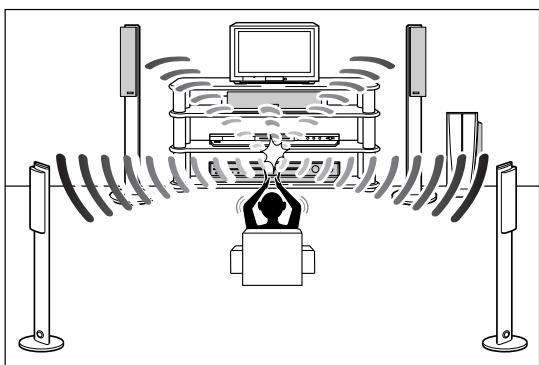
3 When "CLAP YOUR HANDS." appears, clap your hands over your head once while the indications still remain.
- On the display, "SETTING UP" stops flashing.
The receiver starts detecting the level of the sound coming through each speaker (except the subwoofer).
When your clapping sound is detected successfully,
- On the TV screen, "SUCCESSIONAL," "RESULT," and the setting values appear. The setting values are shown for about 10 seconds.
Ex.:
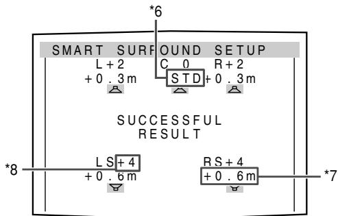
- On the display, "SUCCEEDFUL" appears, then the setting values are shown as follows for about 10 seconds:
Ex.:
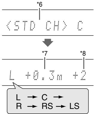
6 Standard channel (the closest speaker). This speaker position now works as the reference position ("0m/ft") and other speakers' distance is shown by the difference with this reference speaker position.
7 Difference of each speaker position in distance (in meters or feet).
*8 Each speaker's output level (-6 to +6).
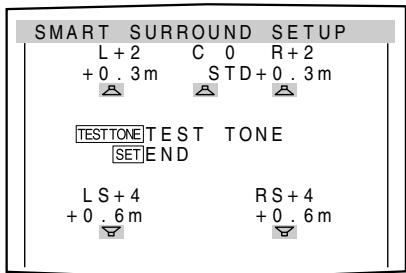
When finishing to show the setting values,
On the TV screen, "COMPLETED" appears, then "TEST TONE" and "END" appear. On the display, "TEST? END?" appears.
- To adjust the speakers' output levels manually, press TEST TONE (see page 29).
- To disappear the on-screen display, press SET or any button except TEST TONE.
- The receiver returns to normal operation mode automatically if no operations are done for about 10 seconds.
Ex.:
When your clapping sound is not detected correctly,
"SETTING UP" appears again after one of the following messages. In this case, repeat step 3.
SILENT: The receiver detects sound from only the left and right front speakers.
- The receiver detects no sound from the front speakers and detects sound from at least one of other speakers.
SILENT-ALL: The receiver cannot detect any sound from any speaker for about 10 seconds.
AGAIN:
- The receiver cannot detect sound from the left or right front speaker.
- The receiver fails to calculate the speakers' output level and difference of each speaker's position in distance.
In the following cases, set the speakers manually.
- When "SILENT" appears twice in succession.
The setting is partially made. (The distance of the speakers from which sound has not been detected is set to “+9.0m (+30ft).”)
The receiver exits from Smart Surround Setup.
- When "MANUAL" appears.
The receiver fails to detect the sound three times. The receiver exits from Smart Surround Setup.
To cancel Smart Surround Setup, press SMART SURROUND SETUP while "SETTING UP" flashes.
- No other operations can be accepted after "SETTING UP" stops flashing. Complete the Smart Surround Setup.
To check the current setting made by Smart Surround Setup, press SMART SURROUND SETUP while the receiver is in normal operation mode.
The setting values appear. On the display, the setting values are shown one after another.
- The current setting is not indicated but "MANUAL" appears if you change the following settings after using Smart Surround Setup: - If you change speaker distance manually.
- If you change one of the speaker sizes either from "NO" to "SMALL" or "LARGE," or from "SMALL" or "LARGE" to "NO."
To check the current setting, see each setting item of the speaker distance (see page 22) and the speaker output level (see page 29). - If you have not used Smart Surround Setup, "NO S.S.S." appears.
NOTES
- The speaker distance and output level manually set will be applied instead of those set by using Smart Surround Setup in the following cases:
- When you change one of the speaker distances (see page 22).
- When you change one of the speaker sizes either from "NO" to "SMALL" or "LARGE," or from "SMALL" or "LARGE" to "NO" (see page 21).
- When you want to adjust the speaker distance and output level manually, see pages 22 and 29.
- When the headphone is in use or "DVD MULTI" is selected as the source, the receiver returns to normal operation mode without showing "TEST TONE."
- The speakers which are set to "NO" in the speaker setting (see page 21) are not indicated clearly on the TV screen.
- Do not clap your hands so hard that it may hurt your hands.
Basic setting items
You can adjust the following items. See pages in parentheses for details.
- You cannot select the items which is not available with the current setting.
- The name of the item shown below is the on-screen display indication and the name in parentheses is the display indication.
| Items and to do | |
| SUBWOOFER (SUBWOOFER) Register your subwoofer. (21) | CROSSOVER (CROSSOVER) Select the cutoff frequency to the subwoofer. (23) |
| FRONT SPK (FRONT SPK) Register your front speaker size. (21) | LFE ATT (LFE ATT) Attenuate the bass (LFE) sounds. (23) |
| CENTER SPK (CENTER SPK) Register your center speaker size. (21) | MIDNIGHT (MIDNIGHT) Reproduce a powerful sound at night. (23) |
| SURR. SPK (SURRND SPK) Register your surround speaker size. (21) | DIGITAL IN 1 (DIGITAL IN1) Select the component connected to the digital coaxial terminal—1(DVR/DVD). (24) |
| DISTANCE UNIT (DIST UNIT) Select the measuring unit for the speaker distance. (22) | DIGITAL IN 2 (DIGITAL IN2) Select the component connected to the digital optical terminal—2(VIDEO). (24) |
| FL SPK DISTANCE (FRNT L DIST)* Register the distance from the left front speaker to your listening point. (22) | DIGITAL IN 3 (DIGITAL IN3) Select the component connected to the digital optical terminal—3(TV). (24) |
| FR SPK DISTANCE (FRNT R DIST)* Register the distance from the right front speaker to your listening point. (22) | AUTO MODE (AUTO MODE) Select Auto Function mode. (24) |
| C SPK DISTANCE (CENTER DIST)* Register the distance from the center speaker to your listening point. (22) | DVD VIDEO (DVD VIDEO) Select the type of the signal transmitted from the DVD recorder or DVD player. (25) |
| LS SPK DISTANCE (SURR L DIST)* Register the distance from the left surround speaker to your listening point. (22) | VCR VIDEO (VCR VIDEO) Select the type of the signal transmitted from the VCR. (25) |
| RS SPK DISTANCE (SURR R DIST)* Register the distance from the right surround speaker to your listening point. (22) | SUPERIMPOSE (SUPERIMPOSE) Select to superimpose the menus on the TV screen. (25) |
| VIRTUAL SB (VIRTUAL SB) Set the virtual surround back speaker. (22) | DOWN MIX (DOWN MIX) Select to convert S-video signals into composite video signals. (25) |
| DUAL MONO (DUAL MONO) Select the Dual Mono sound channel. (22) | Y/C SEPARATE (Y/C SEP.) Select to convert composite video signals into S-video signals. (25) |
| SUBWFR OUT (SUBWFR OUT) Select sounds emitted from the subwoofer. (23) | |
- If you have used Smart Surround Setup on pages 16 and 17, these settings are not required.
NOTE
Adjusting the items may blur the picture when you view the playback picture through RGB connection. If it occurs, set "SUPERIMPOSE" to "SUPERIMPOSE: ON" (see page 25).
Operation through on-screen display menus
You can make adjustments to the basic settings easily by using the on-screen display menus.
Menu operation buttons
On the front panel:
| Button / JOG | To do |
| SETTING button | show setting item previously selected. |
| SET button | move to the selected menu or return to the previous SETTING MENU. |
| MULTI JOG | • select a menu or an item. • change a setting. |
From the remote control:

When operating the receiver using the remote control, set the mode selector to "AUDIO/TV/VCR/STB."
| Button | To do |
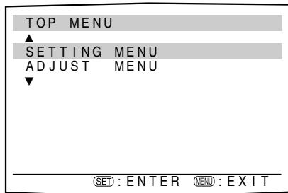
| MENU button | show “TOP MENU.” |
| ▲ /▼ buttons | select a menu or an item. |
| SET button | move to the selected menu or return to the previous SETTING MENU. |
| ▲ /▼ buttons | change a setting. |
Setup menu configuration
- Items on the menus shown below are all set to the initial values when shipping from the factory.
- Some of the menus or some items on the menu cannot be shown or cannot be adjusted depending on the current settings and the connections. (For details, see the respective explanations in this section.)
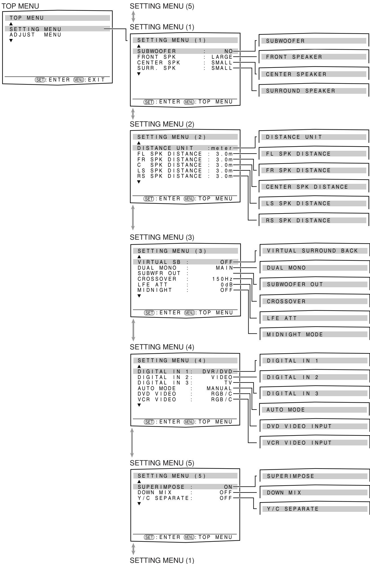
Menu operating procedure
When operating, the on-screen display appears on the TV screen regardless of the SUPERIMPOSE setting (see page 25).
Before you start, remember...
There is a time limit in doing the following steps. If the setting is canceled before you finish, start from step 1 again.
In this section, the operation of the remote control is used for explaining.
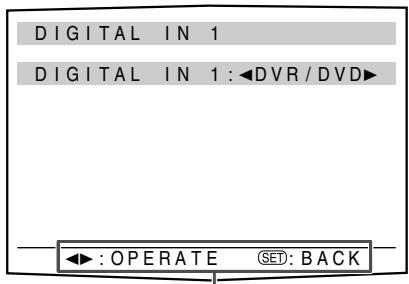
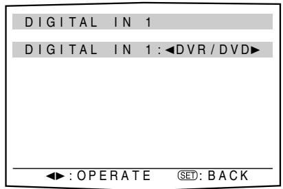
Ex.: When setting DIGITAL IN 1 terminal.
Operations
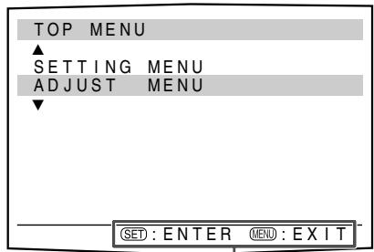
1 To show "TOP MENU," press MENU.
On the TV screen
On the display
SETTING
"SETTING" appears.
"TOP MENU" appears.
2 To select "SETTING MENU," press SET.
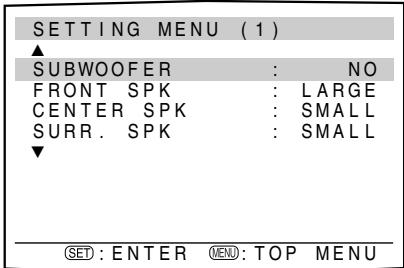
SUBWOOFER
The submenu previously selected appears.
The setting item previously selected appears.
3 To select the desired submenu, press
or repeatedly.
There are five screens from "SETTING MENU (1)"
to "SETTING MENU (5)." To change the screen,
simply pressing or repeatedly. You can go to
the next/previouscreen.
- On the front panel, turn MULTI JOG.
Button indications on the screen
The buttons for operating the menu are shown on the TV screen. You can operate the menu with these buttons.
Usable buttons and their functions
Usable buttons and their functions
The selected submenu appears.
5 To select the appropriate setting, press or repeatedly, then press SET.
The on-screen display returns to the previous SETTING MENU. In this example, "SETTING MENU (4)" appears on the TV screen and "DIGITAL IN1" appears on the display.
- On the front panel, turn MULTI JOG, then press SET.
6 Repeat steps 2 to 5 to set other items if necessary.
NOTES
- To return to "TOP MENU," press MENU on the remote control.
- To exit from menu operations, press MENU on the remote control when "TOP MENU" appears. On the front panel, press SETTING when a menu except "TOP MENU" appears.
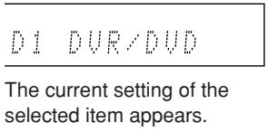
- The setting item previously selected can be shown on the TV screen by pressing SETTING on the front panel when the receiver is in normal operation mode.
Setting the items
When performing the basic settings viewing the indications on the display, the indications are slightly different from what is shown on the on-screen display.
This is because of the limited number of characters shown on the display.
Ex.: "SUBWOOFER: YES" is shown as "SUBWFR: YES" on the display.
-MIDNIGHT MODE: OFF" is shown as "NIGHT: OFF" on the display.
Setting the speakers
Setting subwoofer information—SUBWOOFER
Each time the receiver turns on, the receiver detects the subwoofer connection and automatically changes the setting of the subwoofer.
When you want to change the setting manually, select either one below.
SUBWOOFER:YES
Select when you have connected a subwoofer.
The subwoofer indicator (S.WFR) lights up on the display. You can adjust the subwoofer output level (see page 29).
SUBWOOFER: NO
Select when you have disconnected a subwoofer. Selecting this changes the front speaker size to "LARGE" (see right column).
NOTE
You need to change the setting each time you turn on the receiver if you want to change the subwoofer information set automatically.
Setting the speaker size—FRONT SPEAKER, CENTER SPEAKER, SURROUND SPEAKER
Register the sizes of all the connected speakers.
| LARGE | Select when the cone speaker size is larger than 12 cm. |
| SMALL | Select when the cone speaker size is smaller than 12 cm. |
| NO | Select when you have disconnected a speaker. (Not selectable for the front speakers.) |
Initial setting: SMALL for all speakers*
- When "SUBWOOFER" is set to "SUBWOOFER: NO," the front speaker size is fixed to "LARGE" (and you cannot select "SMALL").
NOTES
- If you have selected "SMALL" for the front speaker size, you cannot select "LARGE" for other speakers.
- If you change one of the speaker sizes either from "NO" to "SMALL" or "LARGE," or from "SMALL" or "LARGE" to "NO," the distance manually set will be applied instead of those set by using Smart Surround Setup.
Setting the speaker distance
The distance from your listening point to the speakers is one of the important elements to obtain the best possible sound effect from the Surround/DSP modes.
By referring to the speaker distance, the receiver automatically sets the delay time of the sound through each speaker so that sounds through all the speakers can reach you at the same time.
- If you have used Smart Surround Setup on pages 16 and 17, this setting is not required.
Measuring unit—DISTANCE UNIT
Select which measuring unit you use.
DISTANCE UNIT: meter Select to set the distance in meters.
DISTANCE UNIT: feet Select to set the distance in feet.
Initial setting: DISTANCE UNIT: meter
■ Speaker distance—
FL SPK DISTANCE (for the left front speaker),
FR SPK DISTANCE (for the right front speaker),
CENTER SPK DISTANCE (for the center speaker),
LS SPK DISTANCE (for the left surround speaker),
RS SPK DISTANCE (for the right surround speaker)
Adjustable range: 0.3m to 9.0m in 0.3m intervals
(1 ft to 30 ft in 1 ft intervals)
Initial setting: 3.0m (10 ft) for all speakers
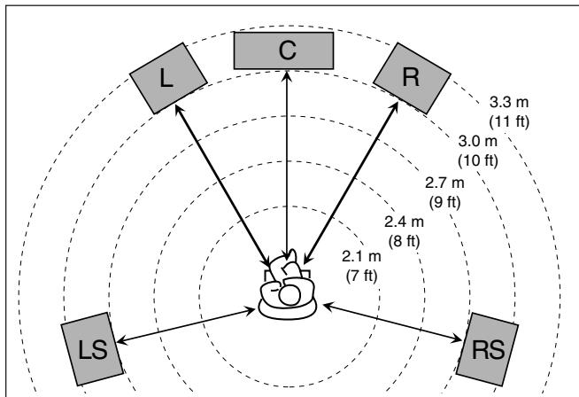
In this case, set the distance as follows:
Left front speaker (L):
"FRONT L: 3.0m (10ft)"
Right front speaker (R):
"FRONT R: 3.0m (10ft)"
Center speaker (C):
"CENTER: 3.0m (10ft)"
Left surround speaker (LS):
"SURROUND L: 2.7m (9ft)"
Right surround speaker (RS):
"SURROUND R: 2.7m (9ft)"
NOTES
- You cannot set the speaker distance for the speakers you have set to "NO."
- If you change one of these settings manually, the distance manually set will be applied instead of those set by using Smart Surround Setup.
Setting the virtual surround back speaker —VIRTUAL SURROUND BACK
You can enjoy the surround back channel while playing back Dolby Digital Surround EX software or DTS-ES software without the surround back speaker—Virtual Surround Back. This function creates the great surround effect from the behind as if you have connected the surround back speaker. Select "VIRTUAL SB: ON" when activating the Virtual Surround Back.
VIRTUAL SB: OFF
Select to deactivate the Virtual Surround Back.
VIRTUAL SB: ON
While you play Dolby Digital Surround EX software or DTS-ES software, the VIRTUAL SB (Surround Back) indicator lights up.
Initial setting: VIRTUAL SB: OFF
NOTES
- When "SURROUND SPEAKER" is set to "SURROUND SPK: NO" (see page 21), this function is not available.
- While playing back DTS-ES Matrix software with DTS 96/24, DTS 96/24 processing will not be performed with the Virtual Surround Back activated. To apply the processing, deactivate the Virtual Surround Back.
- Virtual Surround Back may not be applied to some software.
Selecting the main or sub channel —DUAL MONO
You can select the playback sound (channel) you want while playing digital software recorded (or broadcasted) in Dual Mono mode (see page 39), which includes two monaural channels separately.
DUAL MONO: MAIN
Select to play back the main channel (Ch 1).*
Signal indicator "L" lights up while playing back this channel.
DUAL MONO:SUB
Select to play back the sub-channel (Ch 2).*
Signal indicator "R" lights up while playing back this channel.
DUAL MONO:ALL
Select to play back both the main and sub-channels (Ch 1/Ch 2).* Signal indicators "L" and "R" light up while playing back these channels.
Initial setting: DUAL MONO: MAIN
- Dual Mono signals can be heard from the following speakers—L (left front speaker), R (right front speaker), and C (center speaker), with respect to the current Surround setting:
| Dual Mono setting | Without Surround | With Surround Activated | |||||
| Center speaker setting | |||||||
| SMALL/LARGE | NO | ||||||
| L | R | L | C | R | L | R | |
| MAIN | Ch 1 | Ch 1 | — | Ch 1 | — | Ch 1 | Ch1 |
| SUB | Ch 2 | Ch 2 | — | Ch 2 | — | Ch 2 | Ch 2 |
| ALL | Ch 1 | Ch 2 | — | Ch 1+Ch 2 | — | Ch 1+Ch 2 | Ch 1+Ch 2 |
NOTE
The Dual Mono format is not identical with bilingual broadcasting for TV programs. So this setting does not take effect while watching such bilingual programs.
Setting bass sound
Setting subwoofer output—SUBWOOFER OUT
You can select the type of the signal which can be transmitted through the subwoofer. In other words, you can determine whether or not the bass elements of the front speaker channels are transmitted through the subwoofer regardless of the front speaker size setting (either "SMALL" or "LARGE").
SUBWFR OUT: LFE
Select to emit only the LFE signals (while playing Dolby Digital and DTS software) or the bass elements of the "SMALL" front speakers (while playing any source other than above).
SUBWFR OUT: LFE+MAIN
Select to always emit the bass elements of the front speaker channels (MAIN). While playing Dolby Digital and DTS software, the bass elements and the LFE signals are both emitted.
Initial setting: SUBWFR OUT: LFE
NOTE
When "SUBWOOFER" is set to "SUBWOOFER: NO" (see page 21), this function is not available.
Setting the crossover frequency-CROSSOVER
Small speakers cannot reproduce the bass sounds efficiently. If you use a small speaker in any position, this receiver automatically reallocates the bass sound elements assigned to the small speaker to the large speakers. To use this function properly, set this crossover frequency level according to the size of the small speaker connected.
- If you have selected "LARGE" for all speakers (see page 21), this function will not take effect ("CROSSOVER: OFF" appears).
| CROSSOVER: 80Hz | Select when the cone speaker unit built in the speaker is about 12 cm. |
| CROSSOVER: 100Hz | Select when the cone speaker unit built in the speaker is about 10 cm. |
| CROSSOVER: 120Hz | Select when the cone speaker unit built in the speaker is about 8 cm. |
| CROSSOVER: 150Hz | Select when the cone speaker unit built in the speaker is about 6 cm. |
| CROSSOVER: 200Hz | Select when the cone speaker unit built in the speaker is less than 5 cm. |
Initial setting: CROSSOVER: 150Hz
NOTE
Crossover frequency is not valid for the HEADPHONE and 3D HEADPHONE modes.
Setting the low frequency effect attenuator LFE ATT
If the bass sound is distorted while playing back software encoded with Dolby Digital or DTS, set the LFE level to eliminate distortion.
- This function takes effect only when the LFE signals come in.
| LFE ATT: 0dB | Normally select this. |
| LFE ATT: -10dB | Select when the bass sound is distorted. |
Initial setting: LFE ATT: 0dB
Using the Midnight mode—MIDNIGHT MODE
You can enjoy a powerful sound at night using the Midnight mode.
- Once you have made an adjustment, it is memorized for each source.
MIDNIGHT MODE: OFF
Select when you want to enjoy surround with its full dynamic range. (No effect applied.)
MIDNIGHT MODE:1
Select when you want to reduce the dynamic range a little.
MIDNIGHT MODE: 2
Select when you want to apply the compression effect fully (useful at night).
Initial setting: MIDNIGHT MODE: OFF
From the remote control
You can also make adjustments the following way from the remote control.
Set the mode selector to "AUDIO/TV/VCR/STB."
Press SOUND, then press MIDNIGHT repeatedly to select either one of the above.
NOTE
After pressing SOUND, the numeric buttons work for sound adjustments. To use the numeric buttons to operate your target source, press the corresponding source selecting button before operation; otherwise, the remote control may not work as you intend.
Setting the digital input (DIGITAL IN) terminals—DIGITAL IN 1/2/3
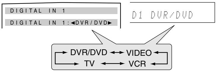
When you use the digital input terminals, register what components are connected to which terminals—DIGITAL IN 1/2/3 (see page 11) so that the correct source name will appear when you select the digital source.
Select one of the following components for each terminal:
| DVR/DVD | For the DVD player (or DVD recorder). |
| VIDEO | For the component connected to theVIDEO IN jacks on the rear of the receiver. |
| VCR | For the VCR. |
| TV | For the TV. |
Initial setting: DVR/DVD (for "DIGITAL IN 1")
VIDEO (for "DIGITAL IN 2")
TV (for "DIGITAL IN 3")
NOTES
- You cannot assign the same component for different terminals.
The priority order for assignment is as follows:
"DIGITAL IN 1" > "DIGITAL IN 2" > "DIGITAL IN 3."
"DIGITAL IN 1" can be set to any component.
Ex.: When "DIGITAL IN 1" is set to "TV."
DIGITAL IN 1: TV
"DVR/DVD," "VIDEO," and "VCR" are selectable for "DIGITAL IN 2."
And when "DIGITAL IN 2" is set to "DVR/DVD."
DIGITAL IN 1: TV
DIGITAL IN 2: DVR/DVD
"VIDEO" and "VCR" are selectable for "DIGITAL IN 3."
- Setting "DIGITAL IN 1" affects "DIGITAL IN 2" and "DIGITAL IN 3" settings. When you have changed "DIGITAL IN 1," confirm the components assigned to "DIGITAL IN 2" and "DIGITAL IN 3."
Setting the Auto Function mode —AUTO MODE
The source will be selected automatically simply by turning on a video component.
- This function takes effect for the video components connected to the receiver using the SCART cable—DVR/DVD and VCR.
Auto Function mode works as follows:
- When a video component is turned on, the receiver selects the video component as the source (and the TV input is changed automatically).
- When a video component currently selected as the source is turned off, the receiver changes the source to the video source previously selected—DVR/DVD, VCR, or VIDEO.
AUTO MODE: AUTO1
Auto Function mode works when the receiver is turned on or when TV Direct is activated.
AUTO MODE: AUTO2
Auto Function mode works when the receiver is turned on or off, or when TV Direct is activated. (When a video component is turned on while the receiver is off, TV Direct is activated and the receiver selects the video component as the source.)
AUTO MODE: MANUAL
You need to select the source manually.
Initial setting: AUTO MODE: MANUAL
When "AUTO MODE: AUTO1" or "AUTO MODE: AUTO2" is selected, the AUTO MODE indicator lights up on the display.
NOTES
- When selecting "VCR" as the source, "AUTO MODE: AUTO1" or "AUTO MODE: AUTO2" may not work if you only turn on the VCR. If this happens, you may need to start playback to activate Auto Function mode.
- When Auto Function mode is set to "AUTO MODE: AUTO2," the TV Direct may be activated after recovery from a power failure.
Selecting the type of the input signalDVDVIDEOINPUT/VCRRVDOINPUT
When you use the AV IN/OUT (SCART) terminals for connecting the DVD recorder (or DVD player) or VCR, register the type of the input signal.
If you have not selected appropriate input signal types, you cannot view the playback picture on the TV.
For the DVD recorder or DVD player (DVD VIDEO):
DVDVIDEO:RGB/C
Select when connecting the DVD recorder (or DVD player) to SCART terminal which receives RGB or composite video signals.
DVDVIDEO:S-VIDEO
Select when connecting the DVD recorder (or DVD player) to SCART terminal which receives S-video signals.
Initial setting: DVD VIDEO: RGB/C
For the VCR (VCRVIDEO):
VCRVIDEO: RGB/C
Select when connecting the VCR to SCART terminal which receives RGB or composite video signals.
VCRVIDEO:S-VIDEO
Select when connecting the VCR to SCART terminal which receives S-video signals.
Initial setting: VCRVIDEO: RGB/C
Superimposing the menus—SUPERIMPOSE
You can select whether or not to superimpose the on-screen display on the TV screen.
SUPERIMPOSE: ON
Select to superimpose the on-screen display on the TV screen.
SUPERIMPOSE: OFF
Select to cancel superimposition. The on-screen display will be shown on the blue background screen.
Initial setting: SUPERIMPOSE: ON
NOTES
- Some on-screen displays appear on the TV screen regardless of this setting.
- The on-screen display does not appear on the TV screen in the following cases:
- When connecting the TV through the VIDEO MONITOR OUT jacks (see page 10).
- When selecting "TV" as the source.
- When the output signals are RGB.
Converting S-video signals into composite video signals—DOWN MIX
You can select whether or not to convert S-video signals into composite video signals.
DOWN MIX: ON Select to convert S-video signals into composite video signals.
DOWN MIX: OFF Select not to use this function.
Initial setting: DOWN MIX: OFF
The converted signals are output through the AV IN/OUT (SCART) terminals (see page 7) as follows:
- S-video signals which are input from the S-VIDEO jack of the VIDEO IN terminal and converted into composite video signals can be output from any AV IN/OUT (SCART) terminal.
- S-video signals which are input from the AV IN/OUT (SCART) terminals and converted into composite video signals can be output through any AV IN/OUT (SCART) terminal except through the same AV IN/OUT (SCART) terminal.
NOTES
- This function is available when satisfying all the following requirements:
- When a video component is connected to this receiver through using at least one of the connections to input S-video signals.
- When a video component or the TV is connected to this receiver through at least one of the AV IN/OUT (SCART) terminals to output composite video signals.
- Either the DVD VIDEO INPUT or the VCR VIDEO INPUT is set to "S-VIDEO" (see left column).
- When using this function, set the input mode of the TV correctly. (Refer also to the manual supplied with the TV.)
Converting composite video signals into S-video signals—Y/C SEPARATE
You can select whether or not to convert composite video signals come from a video component into S-video signals.
Y/C SEPARATE: ON Select to convert composite video signals into S-video signals.
Y/C SEPARATE: OFF Select not to use this function.
Initial setting: Y/C SEPARATE: OFF
NOTES
- This function is available when satisfying all the following requirements:
- When a video component is connected to this receiver through using at least one of the connections to input composite video signals.
- When the TV is connected to this receiver through the AV IN/OUT (SCART) TV terminal to output S-video signals.
- Either the DVD VIDEO INPUT or the VCR VIDEO INPUT is set to "RGB/C" (see left column).
- When the input signals are RGB, set "Y/C SEPARATE" to "Y/C SEPARATE: OFF"; otherwise, the picture will be blurred.
- When using this function, set the input mode of the TV correctly. (Refer also to the manual supplied with the TV.)
You can make sound adjustment to your preference after completing basic setting.
Basic adjustment items
You can adjust the following items. See pages in parentheses for details.
- You cannot select the items which is not available with the current setting.
- The name of the item shown below is the on-screen display indication and the name in parentheses is the display indication.
| Items and to do | |
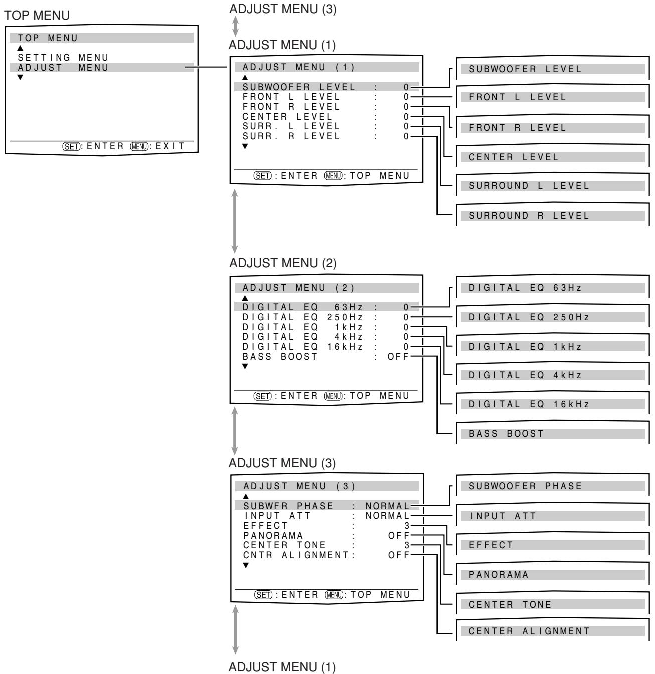
| SUBWOOFER LEVEL (SUBWFR LVL) Adjust the subwoofer output level. (29) | BASS BOOST (BASS BOOST) Boost the bass level. (30) |
| FRONT L LEVEL (FRONT L LVL) Adjust the left front speaker output level. (29) | SUBWFR PHASE (SBWFR PHASE) Select the subwoofer sound phase. (30) |
| FRONT R LEVEL (FRONT R LVL) Adjust the right front speaker output level. (29) | INPUT ATT (INPUT ATT) Attenuate the input level of analogue source. (30) |
| CENTER LEVEL (CENTER LVL) Adjust the center speaker output level. (29) | EFFECT (EFFECT) Adjust the effect level. (31) |
| SURR. L LEVEL (SURR L LVL) Adjust the left surround speaker output level. (29) | PANorama (PANorama) Add wraparound sound effect with side-wall image. (31) |
| SURR. R LEVEL (SURR R LVL) Adjust the right surround speaker output level. (29) | CENTER TONE (CENTER TONE) Make the center tone soft or sharp. (31) |
| DIGITAL EQ 63Hz (D EQ 63Hz)* DIGITAL EQ 250Hz (D EQ 250Hz)* DIGITAL EQ 1kHz (D EQ 1kHz)* DIGITAL EQ 4kHz (D EQ 4kHz)* DIGITAL EQ 16kHz (D EQ 16kHz)* Adjust the equalization pattern of each band. (30) | CNTR ALIGNMENT (CNTR ALIGN) Align the vertical localization of the center channel. (31) |
- If you have used Smart Surround Setup on pages 16 and 17, these settings are not required.
NOTE
Adjusting the items may blur the picture when you view the playback picture through RGB connection. If it occurs, set "SUPERIMPOSE" to "SUPERIMPOSE: ON" (see page 25).
Operation through on-screen display menus
You can make adjustments to the basic settings easily by using the on-screen display menus.
Menu operation buttons
On the front panel:
| Button / JOG | To do |
| ADJUST button | show adjustment item previously selected. |
| SET button | move to the selected menu or return to the previous ADJUST MENU. |
| MULTI JOG | • select a menu or an item. • change a setting. |
From the remote control:
When operating the receiver using the remote control, set the mode selector to "AUDIO/TV/VCR/STB."
| Button | To do |
| MENU button | show “TOP MENU.” |
| ▲ /▼ buttons | select a menu or an item. |
| SET button | move to the selected menu or return to the previous ADJUST MENU. |
| ←/→ buttons | change a setting. |
Setup menu configuration
- Items on the menus shown below are all set to the initial values when shipping from the factory.
- Some of the menus or some items on the menu cannot be shown or cannot be adjusted depending on the current settings and the connections. (For details, see the respective explanations in this section.)
- The "ADJUST MENU (3)" screen cannot be shown depending on the current settings and the connections.
Menu operating procedure
When operating, the on-screen display appears on the TV screen regardless of the SUPERIMPOSE setting (see page 25).
Before you start, remember...
There is a time limit in doing the following steps. If the setting is canceled before you finish, start from step 1 again.
In this section, the operation of the remote control is used for explaining.
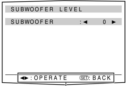
Ex.: When adjusting subwoofer output level.
Operations
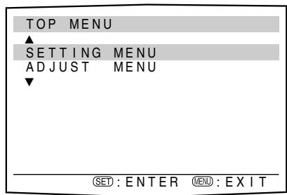
To show "TOP MENU," press MENU. Then press or to select "ADJUST MENU."
- On the front panel, turn MULTI JOG.
On the TV screen
On the display
SETTING
"SETTING" appears.
"TOP MENU" appears.
2 To select "ADJUST MENU," press SET.
SUBWFR LUL
The submenu previously selected appears.
The adjustment item previously selected appears.
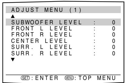
3 To select the desired submenu, press or repeatedly.
There are three screens from "ADJUST MENU (1)" to "ADJUST MENU (3)." To change the screen, simply pressing or repeatedly. You can go to the next/previouscreen.
- On the front panel, turn MULTI JOG.
4 Press SET.
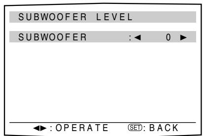
SUBWFR 0
The current setting of the selected item appears.
The selected submenu appears.
5 To adjust the selected item, press or repeatedly, then press SET.
The on-screen display returns to the previous ADJUST MENU. In this example, "ADJUST MENU (1)" appears on the TV screen and "SUBWFR LVL" appears on the display.
- On the front panel, turn MULTI JOG, then press SET.
6 Repeat steps 2 to 5 to set other items if necessary.
NOTES
- To return to "TOP MENU," press MENU on the remote control.
- To exit from menu operations, press MENU on the remote control when "TOP MENU" appears. On the front panel, press ADJUST when a menu except "TOP MENU" appears.
- The adjustment item previously selected can be shown on the TV screen by pressing ADJUST on the front panel when the receiver is in normal operation mode.
Button indications on the screen
The buttons for operating the menu are shown on the TV screen. You can operate the menu with these buttons.
Usable buttons and their functions
Usable buttons and their functions
Adjusting the items
When performing the basic settings viewing the indications on the display, the indications are slightly different from what is shown on the on-screen display.
This is because of the limited number of characters shown on the display.
Ex.: “SUBWOOFER: +10” is shown as “SUBWFR +10” on the display.
- "BASS BOOST: ON" is shown as "B BOOST ON" on the display.
Adjusting speaker output level
- SUBWOOFER LEVEL (subwoofer output level),
- FRONT L LEVEL (left front speaker output level),
- FRONT R LEVEL (right front speaker output level),
- CENTER LEVEL (center speaker output level),
- SURROUND L LEVEL (left surround speaker output level),
- SURROUND R LEVEL (right surround speaker output level)
You can adjust the speaker output levels.
Adjust all the speakers' output levels so that you can listen to the sounds from all the speakers at the same level.
- Once you have made an adjustment, it is memorized for each source.
Adjustable range: -10 (dB) to +10 (dB) (in 1 step intervals)
Initial setting: 0 (dB) for all speakers
From the remote control:
You can also make adjustments the following way from the remote control.
Set the mode selector to "AUDIO/TV/VCR/STB."
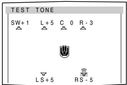
1 Press TEST TONE to check the speakers' output balance.
- On the TV screen, "TEST TONE" appears. The indicator corresponding to the speaker appears while a test tone comes out of the speakers.
EX.:
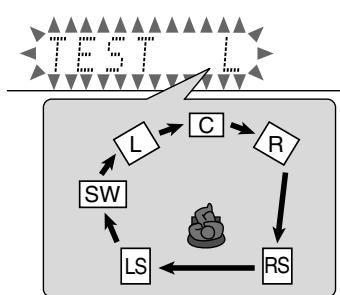
- On the display, "TEST L" starts flashing, and a test tone comes out of the speakers in the following order:
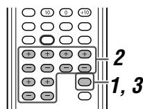
2 Adjust the speaker output levels.
To adjust the left front speaker level (L), press FRONT L +/-.
To adjust the right front speaker level (R), press FRONT R +/-.
To adjust the center speaker level (C), press CENTER +/-.
To adjust the left surround speaker level (LS), press SURR L +/-.
To adjust the right surround speaker level (RS), press SURR R +/-.
To adjust the subwoofer level (SW), press SUBWFR +/-
3 Press TEST TONE again to stop the test tone.
NOTES
- You can adjust the speaker output levels without the test tone.
- No test tone comes out of the speakers and no speaker indication appears on the TV screen corresponding to the speaker which is set to "NO" in the speaker setting (see page 21).
- No test tone is available when the headphone is in use or "DVD MULTI" is selected.
NOTES
- If you have selected "NO" for a speaker (see page 21), the output level for the corresponding speaker is not adjustable.
- While using the headphones, you can adjust only the left and right front speakers' output level.
Adjusting the equalization patterns —DIGITAL EQ 63Hz/250Hz/1kHz/4kHz/16kHz
You can adjust equalization patterns in five frequency bands (center frequency: 63 Hz, 250 Hz, 1 kHz, 4 kHz, 16 kHz) for the front speakers.
- Once you have made an adjustment, it is memorized for each source.
Adjustable range: -8 (dB) to +8 (dB) (in 2 dB intervals)
Initial setting: 0 (dB) for all bands
- When adjustment is made, the EQ indicator lights up on the display.
If no adjustment is required, set all the frequency bands to "0 (dB)." - The EQ indicator goes off from the display.
From the remote control:
You can also make adjustments the following way from the remote control.
Before you start, remember...
There is a time limit in doing the following steps. If the setting is canceled before you finish, start from step 2 again.
Set the mode selector to "AUDIO/TV/VCR/STB."
1 Press SOUND.
2 Press EQ FREQ repeatedly to select the band you want to adjust.
3 Press EQ LEVEL / to adjust the equalization pattern of the selected band.
4 Repeat steps 2 and 3 to adjust other bands.
NOTE
After pressing SOUND, the numeric buttons work for sound adjustments. To use the numeric buttons to operate your target source, press the corresponding source selecting button before operation; otherwise, the remote control may not work as you intend.
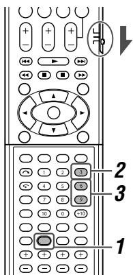
Adjusting the bass sounds
■ Reinforcing the bass—BASS BOOST
You can boost the bass level—Bass Boost.
- Once you have made an adjustment, it is memorized for each source.
BASS BOOST: ON Select to boost the bass level.
The BASS indicator lights up on the display.
BASS BOOST: OFF Select to deactivate the Bass Boost.
Initial setting: BASS BOOST: OFF
NOTE
This function affects only the sound coming out through the front speakers.
From the remote control:
You can also make adjustments the following way from the remote control.
Set the mode selector to "AUDIO/TV/VCR/STB."
Press SOUND, then press BASS BOOST repeatedly.
Each time you press BASS BOOST, the Bass Boost turns on and off alternately.
NOTE
After pressing SOUND, the numeric buttons work for sound adjustments. To use the numeric buttons to operate your target source, press the corresponding source selecting button before operation; otherwise, the remote control may not work as you intend.
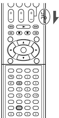
■ Selecting the subwoofer sound phase—SUBWOOFER PHASE
You can change the subwoofer sound phase to your preference.
- Once you have made an adjustment, it is memorized for each source.
PHASE: NORMAL Normally select this.
PHASE: REVERSE Select this when you feel the bass sound is better with this mode rather than with "PHASE: NORMAL."
Initial setting: PHASE: NORMAL
NOTE
This function takes effect only when "SUBWOOFER" is set to "SUBWOOFER:YES" (see page 21).
Attenuating the input signal—INPUT ATT
When the input level of analogue source is too high, the sound will be distorted. If this happens, you need to attenuate the input signal level to prevent the sound distortion.
- Once you have made an adjustment, it is memorized for each source.
INPUT ATT: ON
Select to attenuate the input signal level. The ATT indicator lights up on the display
INPUT ATT: NORMAL Select to deactivate attenuation.
Initial setting: INPUT ATT: NORMAL
Adjusting the sound parameters for the Surround/DSP modes
You can adjust the Surround/DSP sound parameters to your preference.
- For details about the Surround/DSP modes, see pages 38 to 43.
Adjusting the effect level for DSP modes —EFFECT
This setting is available only when one of the DSP modes (except ALL CH ST) is in use. To activate DSP mode, see page 42.
- Once you have made an adjustment, it is memorized for each DSP mode.
Adjustable range: 1 to 5 (in 1 step intervals)
Initial setting: EFFECT: 3
As the number increases, the effect becomes stronger. Normally, select "3."
From the remote control:
You can also make adjustments the following way from the remote control.
Set the mode selector to "AUDIO/TV/VCR/STB."
Press SOUND, then press EFFECT repeatedly.
NOTE
After pressing SOUND, the numeric buttons work for sound adjustments. To use the numeric buttons to operate your target source, press the corresponding source selecting button before operation; otherwise, the remote control may not work as you intend.
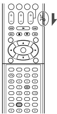
Adjusting the panorama control for Pro Logic II Music—PANorama
This setting is available only when Pro Logic II Music is in use. To activate Pro Logic II Music, see page 42.
- Once you have made an adjustment, it is memorized until you change the setting.
| PANorama: ON | Select to add “wraparound” sound effect with side-wall image. |
| PANorama: OFF | Select to listen to originally recorded sound. |
Initial setting: PANorama: OFF
Making the center tone soft or sharp —CENTER TONE
This setting is available when one of the Surround/DSP modes is in use. To activate Surround/DSP mode, see page 42.
- This setting is common to all Surround modes, and is memorized separately for DSP modes.
-
You cannot adjust the center tone in the following cases:
-
When "CENTER SPEAKER" is set to "CENTER SPK: NO" (see page 21).
- When Dual Mono software is played back.
- While listening with the headphones.
Adjustable range: 1 to 5 (in 1 step intervals)
Initial setting: CENTER TONE: 3
As the number increases, the dialogue becomes stronger. Normally, select "3."
- When the center tone is set to other than "CENTER TONE: 3," the C.TONE indicator lights up on the display.
From the remote control:
You can also make adjustments the following way from the remote control.
Set the mode selector to "AUDIO/TV/VCR/STB."
Press SOUND, then press C.TONE repeatedly.
NOTE
After pressing SOUND, the numeric buttons work for sound adjustments. To use the numeric buttons to operate your target source, press the corresponding source selecting button before operation; otherwise, the remote control may not work as you intend.
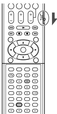
Align the vertical localization of the center channel —CENTER ALIGNMENT
This setting is available when one of the Surround/DSP modes (except "PLII MUSIC" and "ALL CH ST") is in use. To activate Surround/DSP mode, see page 42.
- Once you have made an adjustment, it is memorized for each Surround/DSP mode.
-
You cannot adjust the center alignment in the following cases:
-
When "CENTER SPEAKER" is set to "CENTER SPK: NO" (see page 21).
- When Dual Mono software is played back.
- While listening with the headphones.
| C ALIGNMENT: ON | Select when you cannot feel as if the actors or singers are speaking or singing on the screen. |
C ALIGNMENT: OFF Select not to use this function.
Initial setting: C ALIGNMENT: OFF
Tuner operations
Tuner operations are mainly done from the remote control.
When operating the receiver using the remote control, set the mode selector to "AUDIO/TV/VCR/STB."
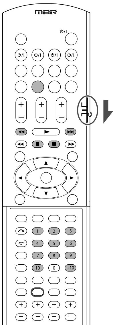
NOTE
When you have selected "FM" or "AM" by using SOURCE SELECTOR on the front panel, the remote control may not work for tuner operations. To use the remote control for tuner operations, select "FM" or "AM" by using the source selecting button on the remote control.
Tuning in to stations manually
From the remote control ONLY:
1 Press FM/AM to select the band.
The last received station of the selected band is tuned in.
Each time you press the button, the band alternates between "FM" and "AM."
| TUNED ST AUTO MUTING | ||||||||
| L | R | |||||||
| S.WFR | ||||||||
| Mhz | ||||||||
2 Press repeatedly or hold TUNING or TUNING until the station you want is tuned in.
- Pressing (or holding) TUNING increases the frequency.
- Pressing (or holding) TUNING decreases the frequency.
NOTES
- When you hold and release TUNING or TUNING, the frequency keeps changing until a station is tuned in.
- When a station of sufficient signal strength is tuned in, the TUNED indicator lights up on the display.
- When an FM stereo program is received, the ST (stereo) indicator also lights up.
Using preset tuning
Once a station is assigned a channel number, the station can be quickly tuned simply by selecting the number. You can preset up to 30 FM and 15 AM (MW) stations.
To store the preset stations
Before you start, remember...
There is a time limit in doing the following steps. If the setting is canceled before you finish, start from step 2 again.
From the remote control ONLY:
1 Tune in to the station you want to preset (see "Tuning in to stations manually" above).
- If you want to store the FM reception mode for this station, select the FM reception mode you want. See "Selecting the FM reception mode" on page 33.
| TUNED ST AUTO MUTING | ||
| L | ||
| S.WFR | ||
2 Press MEMORY.
The channel number position starts flashing on the display for about 5 seconds.
| L S.WFR | R | TUNED ST AUTO MUTING | ||||||
| MHz | ||||||||
3 Press the numeric buttons (1 - 10, + 10) to select a channel number while the channel number position is flashing.
- For channel number 5, press 5.
- For channel number 15, press +10, then 5.
- For channel number 30, press +10, +10, then 10.
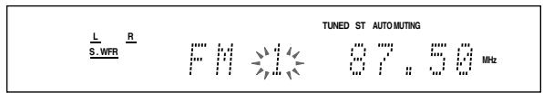
4 Press MEMORY again while the selected channel number is flashing on the display.
The selected channel number stops flashing.
The station is assigned to the selected channel number.
5 Repeat steps 1 to 4 until you store all the stations you want.
To erase a stored preset station
Storing a new station on a used channel number erases the previously stored one.
To tune in a preset station
From the remote control:
1 Press FM/AM to select the band.
The last received station of the selected band is tuned in and the numeric buttons now work for tuner operations.
Each time you press the button, the band alternates between "FM" and "AM."
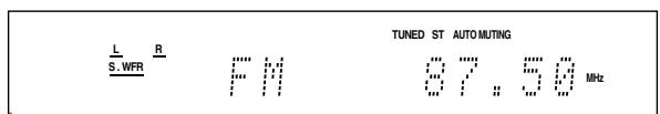
2 Press the numeric buttons (1 - 10, + 10) to select a preset channel number.
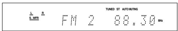
- For channel number 5, press 5.
- For channel number 15, press +10, then 5.
- For channel number 30, press +10, +10, then 10.
On the front panel:
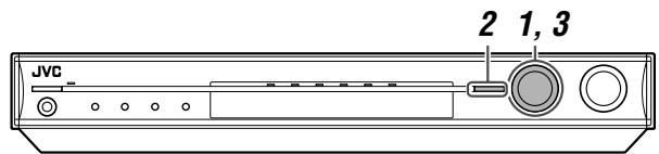
Before you start, remember...
There is a time limit in doing the following steps. If the setting is canceled before you finish, start from step 2 again.
1 Turn SOURCE SELECTOR to select "FM" or "AM."
The last received station of the selected band is tuned in.
2 Press TUNER PRESET.
"P" appears on the display and MULTI JOG now works for selecting preset channels.
3 Turn MULTI JOG to select a preset channel number while "P" appears on the display.
- To increase the preset channel numbers, turn MULTI JOG clockwise.
- To decreases the preset channel numbers, turn MULTI JOG counterclockwise.
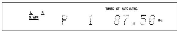
Selecting the FM reception mode
When an FM stereo broadcast is hard to receive or noisy, you can change the FM reception mode while receiving an FM broadcast.
- You can store the FM reception mode for each preset station (see page 32).
From the remote control ONLY:
While listening to an FM station, press FM MODE.
Each time you press the button, the FM reception mode alternates between "AUTO MUTING" and "MONO."
| AUTO MUTING | Normally select this. When a program is broadcast in stereo, you will hear stereo sound; when in monaural, you will hear monaural sound. This mode is also useful to suppress static noise between stations. The AUTO MUTING indicator lights up on the display. |
| MONO | Select this to improve the reception (but stereo effect will be lost). In this mode, you will hear noise while tuning in to the stations. The AUTO MUTING indicator goes off from the display. (The ST indicator also goes off.) |
Initial setting: AUTO MUTING
Using the Radio Data System (RDS) to receive FM stations
Only the buttons on the remote control are used for RDS operations.
When operating the receiver using the remote control, set the mode selector to "AUDIO/TV/VCR/STB."
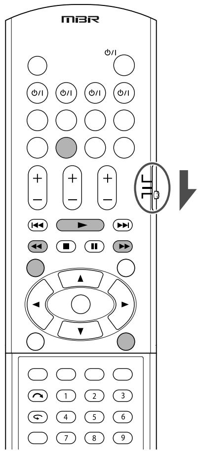
RDS allows FM stations to send an additional signal along with their regular program signals. For example, the stations send their station names, as well as information about what type of program they broadcast, such as sports or music, etc.
When an FM station which provides the RDS service is tuned in, the RDS indicator lights up on the display.
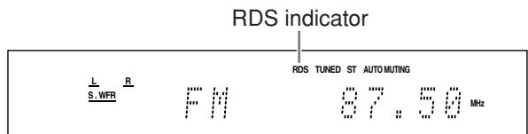
With the receiver, you can receive the following types of RDS signals:
| PS (Program Service): | Shows commonly known station names. |
| PTY (Program Type): | Shows types of broadcast programs. |
| RT (Radio Text): | Shows text messages the station sends. |
| Enhanced Other Networks: | See page 37. |
NOTES
- RDS is not available for AM (MW) broadcasts.
- RDS may not operate correctly if the station tuned is not transmitting RDS signal properly or if the signal strength is weak.
What information can RDS signals provide?
You can see the RDS signals the station sends on the display.
Press DISPLAY while listening to an FM station.
Each time you press the button, the display changes to show the following information:
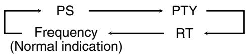
PS (Program Service):
While searching, "PS" appears and then the station names will be displayed. "NO PS" appears if no signal is sent.
PTY (Program Type):
While searching, "PTY" appears and then the type of the broadcast program will be displayed. "NO PTY" appears if no signal is sent.
RT (Radio Text):
While searching, "RT" appears and then text messages the station sends will be displayed. "NO RT" appears if no signal is sent.
Frequency:
Station frequency (non-RDS service).
About characters shown on the display
When the display shows PS, PTY, or RT signals, the following characters are used:
- The display cannot show accented letters, "A" for instance, may stand for accented "A's" like "Ä, Å, Å, Å, Å, ā, ā, ā, Ā, Ā, and Ā."
NOTE
If searching finishes at once, "PS," "PTY," and "RT" will not appear on the display.
Searching for a program by PTY codes
One of the advantages of the RDS service is that you can locate a particular kind of program from the preset channels (see pages 32 and 33) by specifying the PTY codes.
To search for a program using the PTY codes
Before you start, remember...
There is a time limit in doing the following steps. If the setting is canceled before you finish, start from step 1 again.
1 Press PTY SEARCH while listening to an FM station.
"PTY SELECT" flashes on the display.
2 While "PTY SELECT" is flashing, press PTY or PTY until the PTY code you want appears on the display.
3 Press PTY SEARCH again, while the PTY code selected in the previous step is still on the display.
While searching, "SEARCH" and the selected PTY code alternatively appears on the display.
The receiver searches 30 preset FM stations, stops when it finds the one you have selected, and tunes in to that station.
- To stop searching any time, press PTY SEARCH while searching.
- If no program is found, "NOT FOUND" appears on the display.
To continue searching after the first stop
Press PTY SEARCH again while the indications on the display are flashing.
PTY codes
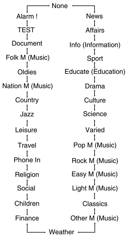
- For details about each code, see "Description of the PTY codes" on page 36.
Description of the PTY codes:
| News: | News. |
| Affairs: | Topical program expanding or enlarging upon the news—debate or analysis. |
| Info (Information): | Programs the purpose of which is to impart advice in the widest sense. |
| Sport: | Programs concerned with any aspect of sports. |
| Educate (Education): | Educational programs. |
| Drama: | All radio plays and serials. |
| Culture: | Programs concerning any aspect of national or regional culture, including language, theatre, etc. |
| Science: | Programs about natural sciences and technology. |
| Varied: | Used for mainly speech-based programs such as quizzes, panel games and personality interviews. |
| Pop M (Music): | Commercial music of current popular appeal. |
| Rock M (Music): | Rock music. |
| Easy M (Music): | Current contemporary music considered to be “easy-listening.” |
| Light M (Music): | Instrumental music, and vocal or choral works. |
| Classics: | Performances of major orchestral works, symphonies, chamber music, etc. |
| Other M (Music): | Music not fitting into any of the other categories. |
| Weather: | Weather reports and forecasts. |
| Finance: | Stock Market reports, commerce, trading, etc. |
| Children: | Programs targeted at a young audience. |
| Social: | Programs about sociology, history, geography, psychology and society. |
| Religion: | Religious programs. |
| Phone In: | Involving members of the public expressing their views either by phone or at a public forum. |
| Travel: | Travel information. |
| Leisure: | Programs about recreational activities. |
| Jazz: | Jazz music. |
| Country: | Songs which originate from, or continue the musical tradition of the American Southern States. |
| Nation M (Music): | Current popular music of the nation or region in that country's language. |
| Oldies: | Music from the so-called “golden age” of popular music. |
| Folk M (Music): | Music which has its roots in the musical culture of a particular nation. |
| Document: | Programs concerning factual matters, presented in an investigative style. |
| TEST: | Broadcasts for testing emergency broadcast equipment or unit. |
| Alarm !!: | Emergency announcement. |
| None: | No program type, unidentified program, or difficult to categorize into particular types. |
Classification of the PTY codes for some FM stations may be different from the above list.
Switching to broadcast program of your choice temporarily
Another convenient RDS service is called "Enhanced Other Networks."
This allows the receiver to switch temporarily to a broadcast program of your choice (TA, NEWS, and/or INFO) from a different station except in the following case:
- The Enhanced Other Networks mode only works when receiving an FM station with the Enhanced Other Networks code.
Before you start, remember...
The Enhanced Other Networks function is only applicable to preset FM stations.
Press TA/NEWS/INFO repeatedly until the program type you want appears on the display.
Each time you press the button, the program type(s) change, and the corresponding indicator(s) light up as follows:
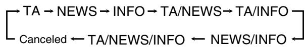
TA: Traffic Announcement in your area.
NEWS: News.
INFO: Program the purpose of which is to impart advice in the widest sense.
How the Enhanced Other Networks function actually works:
If another FM station starts broadcasting the program type you have selected while you are listening to an FM station
The receiver automatically switches to the station. The indicator of the received program type starts flashing.

When the program is over, the receiver goes back to the station previously tuned in, but still remains in Enhanced Other Networks standby mode. The indicator of the received program type stops flashing and remains lit.
If the station currently tuned in starts broadcasting the program type you have selected
The receiver continues to receive the station, but the indicator of the received program type starts flashing.

When the program is over, the indicator of the received program type stops flashing and remains lit, but the receiver remains in Enhanced Other Networks standby mode.
To stop listening to the program selected by Enhanced Other Networks
Press TA/NEWS/INFO repeatedly again so that the program type (TA/NEWS/INFO) indicator goes off from the display. The receiver exits from Enhanced Other Networks standby mode and goes back to the previously selected station.
When an emergency broadcast (Alarm! signal) is sent from an FM station
The receiver automatically tunes in to the station except in the following cases:
- When you are listening to non-RDS Networks—all AM (MW) stations, some FM stations and other sources.
- When the receiver is in standby mode or TV Direct mode.
While receiving an emergency broadcast, "Alarm!" appears on the display.
The TEST signal is used for equipment test—whether it can receive the Alarm! signal correctly
The TEST signal makes the receiver work in the same way as the Alarm! signal does. If the TEST signal is received, the receiver automatically switches to the station broadcasting the TEST signal.
While receiving the TEST signal, "TEST" appears on the display.
NOTES
- Enhanced Other Networks data sent from some stations may not be compatible with this receiver.
- Enhanced Other Networks does not function for some FM stations with RDS service.
- While listening to a program tuned in by the Enhanced Other Networks function, the station does not change even if another network station starts broadcasting a program of the same Enhanced Other Networks data.
- While listening to a program tuned in by the Enhanced Other Networks function, you can only use the TA/NEWS/INFO and DISPLAY.
CAUTION:
If the stations alternate intermittently between the station tuned by the Enhanced Other Networks function and the currently tuned station, press TA/NEWS/INFO repeatedly to cancel the Enhanced Other Networks function.
If you do not press the button, the currently tuned station is received finally, and the indication of the Enhanced Other
Networks data type flashing on the display disappears.
Creating realistic sound fields
Reproducing theatre ambience
In a movie theatre, many speakers are located on the walls to reproduce impressive multi-channel sound, reaching you from all directions.
With these many speakers, sound localization and sound movement can be expressed.
Surround/DSP modes built in this receiver can create almost the same Surround sound as you can feel in a real movie theatre.
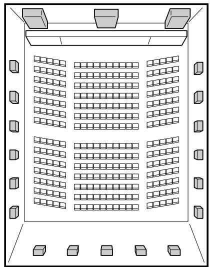

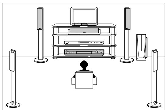
Introducing the Surround modes
Dolby Digital*
Dolby Digital is a digital signal compression method, developed by Dolby Laboratories, and enables multi-channel encoding and decoding.
- When Dolby Digital signal is detected through the digital input, the DOLBY D indicator lights up on the display.
Dolby Digital 5.1CH
Dolby Digital 5.1CH (DOLBY D) encoding method records and digitally compresses the left front channel, right front channel, center channel, left surround channel, right surround channel, and LFE channel signals (total 6 channels, but the LFE channel is counted as 0.1 channel. Therefore, called 5.1 channel).
Dolby Digital enables stereo surround sounds, and sets the cutoff frequency of the surround treble at 20kHz , compared to 7kHz for Dolby Pro Logic. As such, the sound movement and "being-there" feeling are enhanced much more than Dolby Pro Logic.
Another digital surround encoding format introduced by Dolby Laboratories is Dolby Digital EX, which adds the third surround channels, called "surround back."
Compared to the conventional Dolby Digital 5.1CH, these newly added surround back channels can reproduce more detailed movements behind you while viewing the video software. In addition, surround sound localization will become more stable.
- You can use Virtual Surround Back (see page 22) when playing back Dolby Digital Surround EX software. This function creates the great surround effect from the behind as if you have connected the surround back speaker. The VIRTUAL SB indicator lights up on the display.
Dolby Surround
Dolby Pro Logic II
Dolby Pro Logic II is a multi-channel playback format to convert 2-channel software into 5-channel (plus subwoofer). The matrix-based conversion method used for Dolby Pro Logic II makes no limitation for the cutoff frequency of the surround treble and enables stereo surround sound.
- This receiver provides two types of Dolby Pro Logic II modes—Pro Logic II Movie (PLII MOVIE) and Pro Logic II Music (PLII MUSIC).
When Dolby Pro Logic II is activated, the DPLI indicator lights up on the display.
| PLII MOVIE | Suitable for playing any Dolby Surround encoded software. You can enjoy a sound field very close to the one created with discrete 5.1-channel sounds. |
| PLII MUSIC | Suitable for playing any 2-channel stereo software. You can enjoy wide and deep sounds. |
-
To enjoy software encoded with Dolby Digital, connect the source component using the digital terminal on the rear of this receiver. (See page 11.)
-
Manufactured under license from Dolby Laboratories. "Dolby", "Pro Logic", and the double-D symbol are trademarks of Dolby Laboratories.
DTS**
DTS is another digital signal compression method, developed by Digital Theater Systems, Inc., and enables multi-channel encoding and decoding (1ch up to 6.1ch).
- When DTS signal is detected through the digital input, the DTS indicator lights up on the display.
DTS Digital Surround
DTS Digital Surround (DTS) is another discrete 5.1 channel digital audio format available on CD, LD, and DVD software.
Compared to Dolby Digital, the DTS Digital Surround format has a lower audio compression rate which enables it to add breadth and depth to the sounds reproduced. As such, DTS Digital Surround features natural, solid, and clear sound.
Another multi-channel digital surround encoding format introduced by Digital Theater Systems, Inc. is DTS Extended Surround (DTS-ES).
It greatly improves the 360-degree surround impression and space expression by adding the third surround channel—surround back channel.
DTS-ES includes two signal formats with different surround signal recording methods—DTS-ES Discrete 6.1ch and DTS-ES Matrix 6.1ch.
- You can use the Virtual Surround Back (see page 22) when playing back DTS-ES software. This function creates the great surround effect from the behind as if you have connected the surround back speaker. The VIRTUAL SB indicator lights up on the display.
DTS 96/24
In recent years, there has been increasing interest in higher sampling rates both for recording and for reproducing at home. Higher sampling rates allow wider frequency range and greater bit depths provide extended dynamic range.
DTS 96/24 is a multi-channel digital signal format (fs 96 kHz/24 bits) introduced by Digital Theater Systems, Inc. to deliver "better-than-CD sound quality" into the home.
- When DTS 96/24 signal is detected, the DTS and 96/24 indicators light up. You can enjoy its 5.1-channel sound with full-quality.
**“DTS” and “DTS 96/24” are trademarks of Digital Theater Systems, Inc.
When using Surround mode, the sounds come out of the activated speakers which the Surround mode requires.
- If either the surround speakers or center speaker is set to "NO" in the speaker setting (see page 21), the corresponding channel signals are allocated to and emitted through the front speakers.
- If both the surround speakers and center speaker are set to "NO" in the speaker setting (see page 21), JVC's original 3D-PHONIC processing (which has been developed to create the surround effect through the front speakers only) is used. The 3D indicator lights up on the display.
3D HEADPHONE mode
If you connect a pair of headphones while one of the Surround modes is in use, the 3D HEADPHONE mode is activated without respect to the type of software played back.
"3DHEADPHONE" appears on the display and the DSP, 3D, and HP indicators light up.
About other digital signals
Linear PCM
Uncompressed digital audio data used for DVDs, CDs, and Video CDs.
DVDs support 2 channels with sampling rates of 48/96kHz , at quantization of 16/20/24 bits. On the other hand, CDs and Video CDs are limited to 2 channels with 44.1kHz at 16 bits.
- When Linear PCM signal is detected, the LPCM indicator lights up.
Dual Mono
Dual Mono can be easily understood when you think of the bilingual broadcast for TV programs (however, the Dual Mono format is not identical with those analogue formats).
This format is now adopted in Dolby Digital, DTS, and so on. It allows two independent channels (called main channel and sub-channel) to be recorded separately.
- You can select either channel you want to listen to (see page 22).
Introducing the DSP modes
The sound heard in a concert hall, club, etc. consists of direct sound and indirect sound—early reflections and reflections from behind. Direct sounds reach the listener directly without any reflection. On the other hand, indirect sounds are delayed by the distances of the ceiling and walls. These direct sounds and indirect sounds are the most important elements of the acoustic surround effects.
The DSP (Digital Signal Processor) modes can create these important elements, and give you a real "being there" feeling.
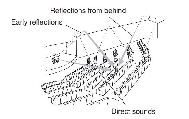
The DSP modes include the following modes:
- Digital Acoustic Processor (DAP) modes—HALL1, HALL2, LIVE CLUB, DANCE CLUB, PAVILION, THEATRE1, THEATRE2
- MONO FILM—Used for all types of 2-channel signals (including Dual Mono signal)
- All Channel Stereo mode (ALL CH ST)
When one of the DSP modes is activated, the DSP indicator lights up on the display.
Digital Acoustic Processor (DAP) modes
You can use the following DAP modes in order to reproduce a more acoustic sound field in your listening room.
| HALL1 | Reproduces the spatial feeling of a large shoebox-shaped hall designed primarily for classical concerts. (Its seating capacity is about 2000.) |
| HALL2 | Reproduces the spatial feeling of a large vineyard-shaped hall designed primarily for classical concerts. (Its seating capacity is about 2000.) |
| LIVE CLUB | Reproduces the spatial feeling of a live music club with a low ceiling. |
| DANCE CLUB | Reproduces the spatial feeling of a rocking dance club. |
| PAVILION | Reproduces the spatial feeling of an exhibition hall with a high ceiling. |
| THEATRE1 | Reproduces the spatial feeling of a large theatre where the seating capacity is about 600. |
| THEATRE2 | Reproduces the spatial feeling of a small theatre where the seating capacity is about 300. |
NOTE
When "THEATRE1" or "THEATRE2" is activated while playing back 2-channel analogue or digital source, the built-in Dolby Pro Logic II decoder is activated and the DPLI indicator lights up.
When using the DAP mode, the sounds come out of all the connected and activated speakers.
- If the surround speakers are set to "NO" in the speaker setting (see page 21), JVC's original 3D-PHONIC processing (which has been developed to create the surround effect through the front speakers only) is used. The 3D indicator lights up on the display.
■ MONO FILM
In order to reproduce a more acoustic sound field in your listening room while viewing monaural sound video software (analogue and 2-channel digital signals including Dual Mono signal), you can use this mode.
The surround effect will be added, and the sound localization of actor's words will be improved.
This mode cannot be used for multi-channel digital signals.
When "MONO FILM" is used, sounds come out of all the connected (and activated) speakers.
- If the surround speakers are set to "NO" in the speaker setting (see page 21), JVC's original 3D-PHONIC processing (which has been developed to create the surround effect through the front speakers only) is used.
The 3D indicator lights up on the display. - If incoming signals change from 2-channel digital signal to another digital signal type, "MONO FILM" is canceled and an appropriate Surround mode is activated.
All Channel Stereo mode (ALL CH ST)
This mode can reproduce a larger stereo sound field using all the connected (and activated) speakers.
This mode cannot be used if the surround speakers are set to "NO" in the speaker setting (see page 21).
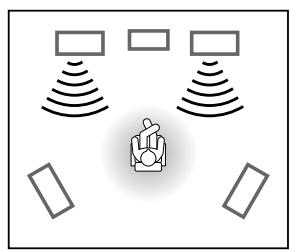
Sound reproduced from normal stereo

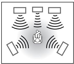
Sound reproduced from All Channel Stereo mode
3D HEADPHONE mode
If you connect a pair of headphones while one of the DSP modes is in use, the 3D HEADPHONE mode is activated without respect to the type of software played back. "3DHEADPHONE" appears on the display and the DSP, 3D, and HP indicators light up.
Activating the Surround/DSP modes
Available Surround/DSP modes vary depending on the incoming signals. For details, see page 43.
Activating one of the Surround/DSP modes automatically recalls the memorized settings and adjustments.
To adjust the speaker output level, see page 29.
- To adjust the effect level for the DSP mode (except All Channel Stereo mode,) see page 31.
- To add "wraparound" sound effect to "PLII MUSIC" (PANorama control,) see page 31.
- To adjust the vertical localization of the center channel for Surround/DSP modes (except "PLII MUSIC" and "ALL CH ST") (center alignment,) see page 31.
NOTES
- You cannot use any Surround/DSP modes when selecting "DVD MULTI" as the playback source.
- You cannot select All Channel Stereo mode if the surround speakers are set to "NO" in the speaker setting (see page 21).
- You cannot select MONO FILM mode if an incoming signal is a multi-channel (more than 2 channel) digital signal.
- The on-screen display appears on the TV screen to show the Surround/DSP mode name for 5 seconds when you select the Surround/DSP mode.
To cancel the function, set "SUPERIMPOSE" to "SUPERIMPOSE: OFF" (see page 25).
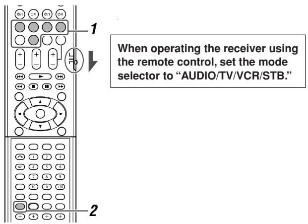
From the remote control:
1 Select and play any source other than "DVD MULTI."
- Make sure you have selected the input mode (analogue or digital) correctly.
2 Press SURROUND repeatedly to select the Surround/DSP mode you want.
Ex.: When "DOLBY D" is selected for Dolby Digital multichannel software:
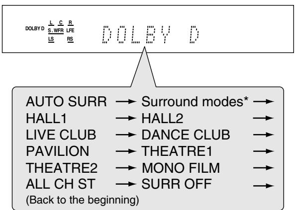
To cancel Surround/DSP modes
Press SURROUND repeatedly so that "SURR OFF" appears on the display.
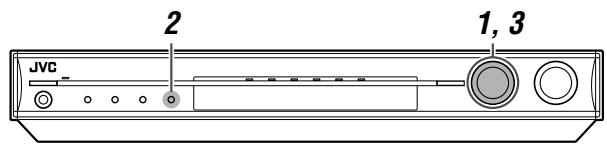
On the front panel:
Before you start, remember...
There is a time limit in doing the following steps. If the setting is canceled before you finish, start from step 2 again.
1 Select and play any source other than "DVD MULTI."
- Make sure you have selected the input mode (analogue or digital) correctly.
2 Press SURROUND.
MULTI JOG now works for selecting Surround/DSP modes.
3 Turn MULTI JOG to select the Surround/DSP mode you want.
Ex.: When "DOLBY D" is selected for Dolby Digital multi-channel software:
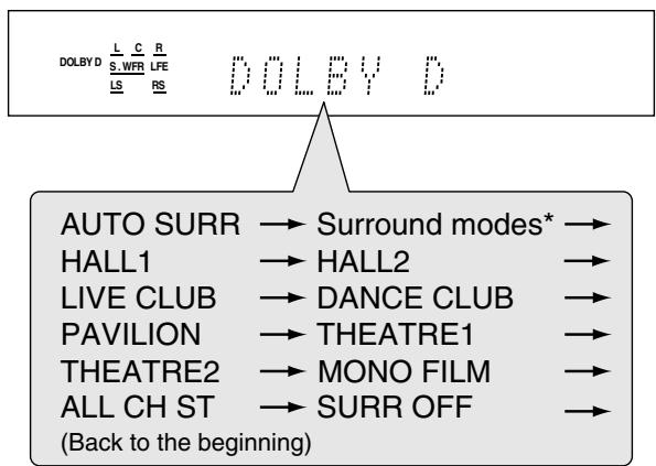
To cancel Surround/DSP modes
Turn MULTI JOG so that "SURR OFF" appears on the display.
NOTE
The initial setting is "AUTO SURR."
- Available Surround modes vary depending on the incoming signals. For details, see "Available Surround and DSP modes according to the incoming signal" on page 43.
When you select "AUTO SURR" (Auto Surround)
You can enjoy the Surround mode easily.
- For details about the Surround modes, see pages 38 and 39.
- When "AUTO SURR" is activated, the AUTO SR indicator lights up on the display.
How does "AUTO SURR" work?
- If a multi-channel signal comes in, an appropriate Surround mode will be selected automatically.
- If a Dolby Digital 2-channel or DTS 2-channel signal with surround signal comes in, "PLII MOVIE" will be selected.
- If a Dolby Digital 2-channel or DTS 2-channel signal without surround signal, or a Linear PCM signal comes in, "SURR OFF (stereo)" will be selected.
Virtual Surround Back
When playing Dolby Digital Surround EX or DTS-ES software, you can enjoy surround back channel playback using the Virtual Surround Back.
Ex.: When playing back DTS-ES software.
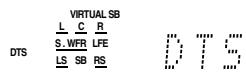
To activate the Virtual Surround Back, see page 22.
NOTES
- "AUTO SURR" does not take effect in the following cases: - While playing an analogue source.
- While selecting one of the fixed digital decode modes—"DOLBY D" or "DTS" (see page 13).
- While listening with the headphones, the 3D HEADPHONE mode (see pages 39 and 41) is activated without respect to the type of software played back.
- When "AUTO SURR" is selected, sound may not come out at the beginning of playback. If it occurs, select a Surround mode manually (see page 42).
Available Surround and DSP modes according to the incoming signal
The name of the mode shown below is the display indication.
| Modes Incoming signal | Surround modes | DSP modes | HEADPHONE mode | Surround/DSP off |
| Dolby Digital (multi-channel) | DOLBY D | HALL1/2, LIVE CLUB, DANCE CLUB, PAVILION, THEATRE1/2, ALL CH ST*2 | HEADPHONE, 3D HEADPHONE | SURRND OFF (stereo) |
| Dolby Digital Surround EX | DOLBY D | |||
| DTS (multi-channel) | DTS | |||
| DTS-ES | DTS | |||
| (Virtual Surround Back) | ||||
| Dual Mono | DUAL MONO | HALL1/2, LIVE CLUB, DANCE CLUB, PAVILION, THEATRE1/2, MONO FILM, ALL CH ST*2 | ||
| Dolby Digital (2-channel) | PLII MOVIE, PLII MUSIC | |||
| DTS (2-channel) | ||||
| Linear PCM | ||||
| Analogue |
1 Virtual Surround Back may not be applied to some software.
2 Not selectable if the surround speakers are set to "NO" in the speaker setting (see page 21).
Operating other JVC products
You can use the supplied remote control to operate not only this receiver but also other JVC products.
-
Refer also to the manuals supplied with the other products. Some JVC VCRs can accept two types of the control signals—remote codes “A” and “B.”
-
When operating a VCR whose remote control code is set to "A," set the manufacturer's code to "01."
- When operating a VCR whose remote control code is set to "B," set the manufacturer's code to "02."
The initial setting is "01." For details about the setting, see "Changing the transmittable signals for operating a VCR" on page 47.
- To operate other products, aim the remote control directly at the remote sensor on the target product.
TV
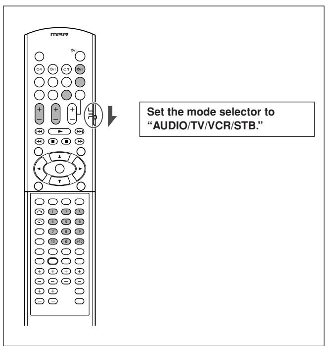
You can always perform the following operations:
| TV Ⓞ/l: | Turn on or off the TV. |
| TV VOL +/-: | Adjust the volume on the TV. |
| TV/VIDEO: | Change the input mode (either video input or TV tuner) on the TV. |
After pressing TV, you can perform the following operations on the TV.
| CHANNEL +/-: | Change the channel numbers. |
| 1 - 9, 0, 100+: | Select the channel numbers. |
| TV RETURN (10): | Function as the TV RETURN button. (Switches between the previous channel and the current channel.) |

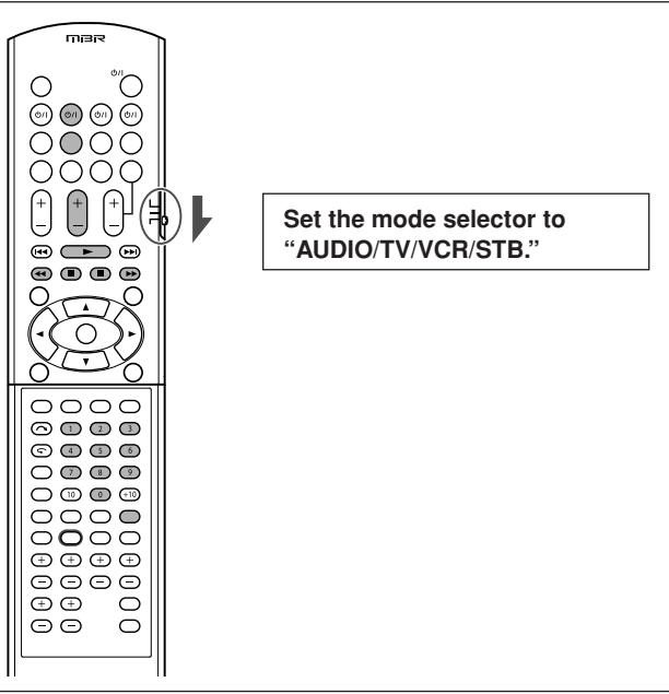
You can always perform the following operation:
| VCR Ⓒ/I: | Turn on or off the VCR. |
After pressing VCR, you can perform the following operations on the VCR.
| CHANNEL +/-: | Change the channel numbers on the VCR. |
| 1 - 9, 0: | Select the channel numbers on the VCR. |
| ►: | Start playback. |
| ■: | Stop playback. |
| II: | Pause playback. To release it, press►. |
| ►►: | Fast-wind a tape. |
| ↔←: | Rewind a tape. |
| REC PAUSE: | Enter recording pause. To start recording, press this button then►. |

DVD recorder or DVD player
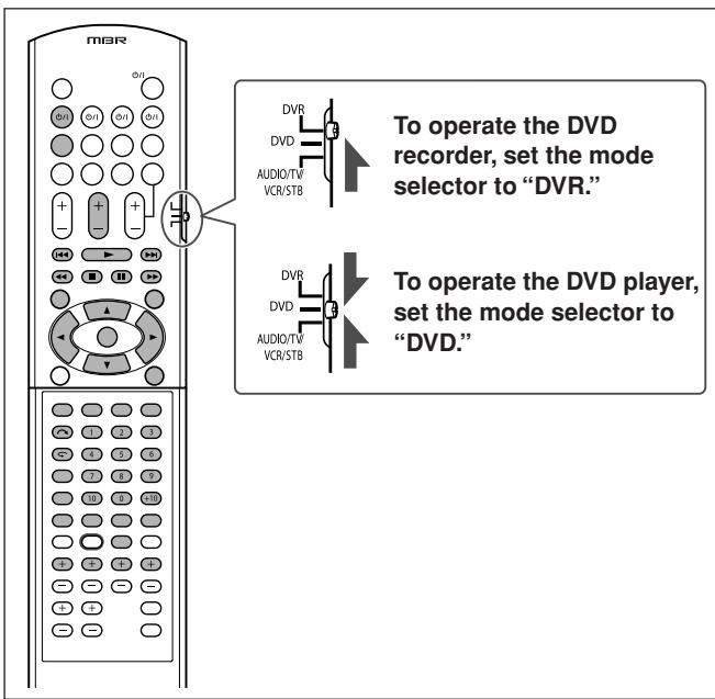
After setting the mode selector correctly, you can perform the following operations on the DVD recorder or DVD player.
See the instructions supplied with the DVD recorder or DVD player for details.
Changing the remote control code for DVD recorder
Some JVC DVD recorders can accept four types of the control signals. You can assign one of the four codes to the remote control supplied with this receiver for operating your DVD recorder. For details, refer to the manual supplied with the DVD recorder.
Initial setting: 03
1 Set the mode selector to "DVR."
2 Press and hold DVR/DVD /
3 Press DVR/DVD.
4 Enter the remote control code you want using buttons 1 - 4, and 0.
EX.: To enter the code "2", press 0, then 2.
| Code for DVR | Number to enter |
| 1 | 01 |
| 2 | 02 |
| 3 | 03 |
| 4 | 04 |
5 Release DVR/DVD 念 /
Now, the remote control code has been changed.
You can always perform the following operation:
| DVR/DVD Ⓒ/I: | Turn on or off the DVD recorder or DVD player. |
| ►: | Start playback. |
| ■: | Stop playback. |
| II: | Pause playback. To release it, press►. |
| ►■: | Skip to the beginning of the next chapter. |
| ←▲: | Return to the beginning of the current (or previous) chapter. |
| ►: | Fast-forward playback. |
| ←▲: | Fast-reverse playback. |
TOP MENU/MENU:
Display the menu recorded on discs.
ON SCREEN: Shows the on-screen bar.
/ / / : Select an item on the menu screen.
ENTER: Enter the selected item, channel number, chapter/title number, or track number (if required).
You can also use the following buttons to operate JVC DVD recorder and/or DVD player if it supports the corresponding function:
For various settings:
| AUDIO: | Select the audio language/channel. |
| SUBTITLE: | Select the subtitle language. |
| SET UP: | Display the Preference display. |
| VFP: | Show the picture adjustment screen. |
| PROGRESSIVE*: Change the scanning mode. | |
| ANGLE: | Select the view angle. |
For various playback:
| (one touch replay): Move the playback position back 10 seconds before the current position. | |
| RETURN: | Return to the main menu during menu operation. |
| CANCEL: | Cancel the programmed track, etc. |
Only for DVD recorder operations:
| CHANNEL +/-: | Change the channel numbers. |
| DVD/HDD: | Select the DVD recorder or HDD deck. (Only for a DVD recorder incorporated with HDD deck.) |
| ( skip): | Move the playback position ahead 30 seconds after the current position. |
| 1-9,0: | Select a channel number (while stopped) or a chapter/title number, track number (while playing back). Press ENTER to enter the number. |
| REC MODE: | Select the recording mode. |
| REC PAUSE: | Enter recording pause. To start recording, press▶. |
| DISPLAY: | Change the display information. |
Only for DVD player operations:
| fs/Rate*: | Show the sampling frequency. |
| TITLE/GROUP: | Make the numeric buttons work for selecting the title/group number. |
| ZOOM: | Zoom in and out. |
| 1-10, 0, +10: | Select a chapter/title number, track number, menu item, etc. |
| DVD/CARD: | Select the disc or memory card to play. (Only for a DVD player incorporated with memory card slots.) |
| DIMMER: | Change the display brightness. |
| THUMBMAIL: | Show the thumbnail screen for JPEG discs. |
| SLIDE: | Start the slide show playback for JPEG discs. |
| 3D/S.EFFECT: | Apply the 3D effect. |
| PAGE: | Show browsable still pictures on DVD Audio discs. |
- Press and hold when using these buttons.
If these buttons do not function normally, use the remote control supplied with your DVD recorder or DVD player. Refer also to the manuals supplied with the DVD recorder or DVD player for details.
Operating other manufacturers' products
By changing the transmittable signals, you can use the supplied remote control to operate other manufacturers' products.
- Refer also to the manuals supplied with the other products.
- To operate those components with the remote control, first you need to set the manufacturers' codes each for the TV, VCR, and STB.
- After replacing batteries of the remote control, set the manufacturers' codes again.
Changing the transmittable signals for operating a TV
Set the mode selector to "AUDIO/TV/VCR/STB."
1 Press and hold TV /
2 Press TV.
3 Enter the manufacturer's code using buttons 1-9, and 0.
See "Manufacturers' codes for TV" on the right.
4 Release TV 1/1.
Now, you can perform the following operations on the TV.
| TV Ⓞ/I: | Turn on or off the TV. |
| TV VOL +/-: | Adjust the volume on the TV. |
| TV/VIDEO: | Change the input mode (either TV orVIDEO). |
After pressing TV, you can perform the following operations on the TV.
| CHANNEL +/-: | Change the channel numbers. |
| 1 – 9, 0, 100+ (+10): | Select the channel numbers. |
See the instructions supplied with the TV for details.
5 Try to operate your TV by pressing TV 念 /念
When your TV turns on or off, you have entered the correct code.
If more than one code is listed for your brand of TV, try each one until the correct one is entered.
Manufacturers' codes for TV
| Manufacturer | Codes |
| JVC | 01 |
| Akai | 02, 05 |
| Blaupunkt | 03 |
| Daewoo | 09, 30, 31 |
| Fenner | 04, 30, 31 |
| Fisher | 05 |
| Grundig | 06 |
| Hitachi | 07, 08 |
| Irradio | 02, 05 |
| Magnavox | 09 |
| Mitsubishi | 10, 32 |
| Mivar | 03 |
| Nokia | 11, 33 |
| Nordmende | 12, 13, 17, 25 – 27 |
| Orion | 14 |
| Panasonic | 15, 16 |
| Philips | 09 |
| Saba | 12, 13, 17, 25 – 27 |
| Samsung | 09, 18, 31 |
| Sanyo | 05 |
| Schneider | 02, 05 |
| Sharp | 19 |
| Sony | 20 – 24 |
| Telefunken | 12, 13, 17, 25 – 27 |
| Thomson | 12, 13, 17, 25 – 27, 29 |
| Toshiba | 28 |
Initial setting: 01
Manufacturers' codes are subject to change without notice. If they are changed, this remote control cannot operate the equipment.
Changing the transmittable signals for operating a VCR
Set the mode selector to "AUDIO/TV/VCR/STB."
1 Press and hold VCR
2 Press VCR.
3 Enter the manufacturer's code using buttons 1-9, and 0.
See "Manufacturers' codes for VCR" on the right.
4 Release VCR 1/1.
Now, you can perform the following operation on the VCR.
| VCR 0/1: | Turn on or off the VCR. |
After pressing VCR, you can perform the following operations on the VCR.
| CHANNEL +/-: | Change the channel numbers on the VCR. |
| 1 - 9, 0: | Select the channel numbers on the VCR. |
| ►: | Start playback. |
| ■: | Stop playback. |
| II: | Pause playback. |
| ►►: | Fast-wind a tape. |
| ↔←: | Rewind a tape. |
See the instructions supplied with the VCR for details.
5 Try to operate your VCR by pressing VCR /1
When your VCR turns on or off, you have entered the correct code.
If more than one code is listed for your brand of VCR, try each one until the correct one is entered.
Manufacturers' codes for VCR
| Manufacturer | Codes |
| JVC | 01, 02 |
| Akai | 02, 37 |
| Bell+Howell | 04, 17 |
| Blaupunkt | 05 |
| CGM | 04, 06, 17 |
| Daewoo | 35 |
| Digital | 06 |
| Fisher | 04, 17 |
| G.E. | 07 |
| Grundig | 08 |
| Hitachi | 09, 10 |
| Loewe | 06, 11, 12 |
| Magnavox | 05, 06 |
| Mitsubishi | 13 – 16 |
| Nokia | 17 |
| Nordmende | 18 – 20, 32 |
| Orion | 21 |
| Panasonic | 22 |
| Philips | 06, 23 |
| Phonola | 06 |
| Saba | 18 – 20, 24, 32 |
| Samsung | 25, 26 |
| Sanyo | 04, 17 |
| Sharp | 27, 28 |
| Siemens | 08 |
| Sony | 29 – 31, 36 |
| Telefunken | 18 – 20, 32, 33 |
| Toshiba | 34 |
Initial setting: 01
Manufacturers' codes are subject to change without notice. If they are changed, this remote control cannot operate the equipment.
Changing the transmittable signals for operating an STB
Set the mode selector to "AUDIO/TV/VCR/STB."
1 Press and hold STB /L
2 Press STB.
3 Enter the manufacturer's code using buttons 1-9, and 0.
See "Manufacturers' codes for STB" on the right.
4 Release STB /
Now, you can perform the following operation on the STB.
Manufacturers' codes for STB
| STB Ⓒ/I: | Turn on or off the STB. |
| After pressing STB, you can perform the following operations on the STB. | |
| CHANNEL +/-: | Change the channel numbers on the STB. |
| 1 - 9, 0: | Select the channel numbers on the STB. |
See the instructions supplied with the STB for details.
5 Try to operate your STB by pressing STB /1
When your STB turns on or off, you have entered the correct code.
If more than one code is listed for your brand of STB, try each one until the correct one is entered.
| Manufacturer | Codes |
| JVC | 01, 02 |
| Amstrad | 03 – 06, 33 |
| BT | 01 |
| Canal Satellite | 22 |
| Canal + | 22 |
| D-Box | 26 |
| Echostar | 19 – 21, 23 |
| Finlux | 11 |
| Force | 30 |
| Galaxis | 29 |
| Grundig | 07, 08 |
| Hirschmann | 07, 19, 39 |
| ITT Nokia | 11 |
| Jerrold | 16 |
| Kathrein | 13, 14, 36 |
| Luxor | 11 |
| Mascom | 34 |
| Maspro | 13 |
| Nokia | 26, 28, 35 |
| Pace | 10, 27, 33 |
| Panasonic | 15 |
| Philips | 09, 25 |
| RFT | 12 |
| Saba | 37 |
| Sagem | 24, 31 |
| Salora | 11 |
| Selector | 31 |
| Skymaster | 12, 38 |
| Thomson | 37 |
| TPS | 24 |
| Triax | 32 |
| Videoway | 17, 18 |
| Wisi | 07 |
Initial setting: 01
Manufacturers' codes are subject to change without notice. If they are changed, this remote control cannot operate the equipment.
| PROBLEM | POSSIBLE CAUSE | SOLUTION | |
| Power | The power does not come on. | The power cord is not plugged in. | Plug the power cord into an AC outlet. |
| The receiver turns off (enters standby mode). | Speakers are overloaded because of high volume. | 1. Stop the playback source.2. Turn on the receiver again, then turn the volume down. | |
| Speakers are overloaded because of a short circuit at the speaker terminals. | Check the speaker wiring. If speaker wiring is not short-circuited, contact your dealer. | ||
| The receiver is overloaded because of a high voltage. | Consult your dealer after unplugging the power cord. | ||
| "OVER HEAT" flashes on the display, then the receiver turns off. | The receiver is overloaded because of high volume or long time usage. | Turn on the receiver again. If the receiver turns off soon, consult your dealer after unplugging the power cord. | |
| Sound and picture | No sound from speakers. | Speaker signal cables are not connected. | Check speaker wiring, then reconnect if necessary (see page 6) after unplugging the power cord. |
| Connections are incorrect. | Check the audio connections (see pages 7 to 11) after unplugging the power cord. | ||
| An incorrect source is selected. | Select the correct source. | ||
| Muting is activated. | Press MUTING to cancel the mute (see page 15). | ||
| An incorrect input mode (analogue or digital) is selected. | Select the correct input mode (analogue or digital). | ||
| TV Direct is activated. | Deactivate TV Direct (see page 14). | ||
| Sound from one speaker only. | Speaker signal cables are not connected properly. | Check speaker wiring and reconnect if necessary (see page 6) after unplugging the power cord. | |
| Bass sound is reinforced too much when listening in stereo. | Appropriate bass level is not selected. | Adjust audio position level (see page | |
| Sounds are intermittently distorted by the outside noise such as a lightning discharge. | When you use the digital coaxial connection, the sounds may be intermittently distorted by the outside noise such as a lightning discharge but the sound will be restored automatically. | This is not a malfunction. | |
| Picture is blurred. | RGB signals are input when Y/C SEPARATE is activated. | Deactivate Y/C SEPARATE (see page 25). | |
| Adjusting the items may blur the picture when you view the playback picture through RGB connection. | Set "SUPERIMPOSE" to "SUPERIMPOSE: ON" (see page 25). | ||
| No picture is displayed on the monitor. | Connections are incorrect. | Check the video connections (see pages 7 to 10) after unplugging the power code. | |
| Input mode is incorrect. | Check the video component input mode (see page 25). | ||
| The DOWN MIX or Y/C SEPARATE setting is incorrect. | Select the correct DOWN MIX or Y/C SEPARATE setting (see page 25). | ||
| Remote control | Remote control does not operate as you intend. | The remote control is not ready for your intended operation. | Set the mode selector correctly, then press the corresponding source selecting button or SOUND before operation |
| Remote control does not work. | There is an obstruction hiding the remote sensor on the receiver. | Remove the obstruction. | |
| Batteries are weak. | Replace batteries. | ||
| The mode selector is set to the incorrect position. | Set the mode selector to the proper position. | ||
| Buttons cannot be used. | TV Direct is activated. | Deactivate TV Direct (see page 14). | |
| Tuner | Continuous hiss or buzzing during FM reception. | Incoming signal is too weak. | Connect an outdoor FM antenna or contact your dealer. |
| The station is too far away. | Select another station. | ||
| The wrong antenna is being used. | Check with your dealer to be sure you have the correct antenna. | ||
| Antennas are not connected properly. | Check the connections. | ||
| Occasional cracking noise during FM reception. | Ignition noise from automobiles. | Move the antenna farther from automobile traffic. | |
Specifications
Designs and specifications are subject to change without notice.
Amplifier
Output Power
At stereo operation:
Front channels: 100 W per channel, min. RMS, both channels driven into 6 Ω at 1 kHz with no more than 10% total harmonic distortion. (IEC268-3)
At surround operation:
Front channels: 100 W per channel, min. RMS, driven into 6 Ω at 1 kHz with no more than 0.8% total harmonic distortion.
Center channel: 100 W, min. RMS, driven into 6 Ω at 1 kHz, with no more than 0.8% total harmonic distortion.
Surround channels: 100 W per channel, min. RMS, driven into 6 Ω at 1 kHz, with no more than 0.8% total harmonic distortion.
Audio
Audio Input Sensitivity/Impedance:
VIDEO, DVD MULTI, DVR/DVD, VCR, TV: 330 mV/47 kΩ
Audio Input (DIGITAL IN)*:
Coaxial: DIGITAL IN 1(DVR/DVD): 0.5V(· ) / 75
Optical: DIGITAL IN 2(VIDEO), 3(TV): -21 dBm to -15 dBm (660 nm ±30 nm)
- Corresponding to Linear PCM, Dolby Digital, and DTS (with sampling frequency—32 kHz, 44.1 kHz, 48 kHz).
Audio Output Level:
MONITOR OUT, DVR/DVD, VCR, TV: 330
Signal-to-Noise Ratio ('66 IHF/DIN): 80 dB/62 dB
Frequency Response (6 Ω): 20 Hz to 20 kHz (±1 dB)
Bass Boost: +4 dB ±1 dB at 100 Hz
Equalization:
Center frequency: 63 Hz, 250 Hz, 1 kHz, 4 kHz, 16 kHz
Control range: ±8 dB
Video
Video Input Sensitivity/Impedance:
Composite video: DVR/DVD, VCR, TV, VIDEO:
1 V(p-p)/75 Ω
S-video: DVR/DVD, VCR, VIDEO:
Y (luminance): 1V(p - p) / 75
C (chrominance, burst): 0.3 V(p-p)/75 Ω
RGB:DVR/DVD,VCR: 0.7V(· ) / 75
Component: DVR/DVD,VIDEO:
Y (luminance): 1V(p - p) / 75
Video Output Level/Impedance:
Composite video: DVR/DVD, VCR, TV: 1 V(p-p)/75 Ω
S-video: TV:
Y (luminance): 1V(p - p) / 75
C (chrominance, burst): 0.3 V(p-p)/75 Ω
RGB:TV: 0.7V(p - p) / 75
Component: MONITOR OUT:
Y (luminance): 1V(p - p) / 75
Synchronization: Negative
FM tuner (IHF)
Tuning Range: 87.50 MHz to 108.00 MHz
Usable Sensitivity:
Monaural: 17.0 dBf (1.95 V/75 Ω)
50 dB Quieting Sensitivity:
Monaural: 21.3 dBf (3.2 V/75 Ω)
Stereo: 41.3 dBf (31.5 V/75Ω)
Stereo Separation at Rec out: 35 dB at 1 kHz
AM (MW) tuner
Tuning Range: 522 kHz to 1629 kHz
General
Power Requirements: AC 230 V~, 50 Hz
Power Consumption: 110 W (at operation)
2 W (in standby mode)
Dimensions (W× H× D) : 435mm× 70mm× 317.2mm
Mass: 6.3kg
JVC


- HOME CINEMA CONTROL CENTER
- RX-F31S
- IMPORTANT for the U.K.
- IMPORTANT:
- Caution—/I STANDBY/ON button!
- CAUTION
- Caution: Proper Ventilation
- SAFETY INSTRUCTIONS "SOME DOS AND DON'TS ON THE SAFE USE OF EQUIPMENT"
- ABOVE ALL
- Parts identification
- Remote control
- Getting started
- Before Installation
- General precautions
- Locations
- Handling the receiver
- CAUTION:
- Checking the supplied accessories
- Putting batteries in the remote control
- Connecting the FM and AM (MW) antennas
- AM (MW) antenna connection
- FM antenna connection
- NOTES
- Connecting the speakers
- Speaker Layout Diagram
- CAUTIONS:
- Connecting the powered subwoofer
- NOTE
- Connecting video components
- SCART connection
- Turn off all components before making connections.
- For an analogue decoder
- For T-V LINK
- Audio/video connection
- - Connecting a DVD recorder or DVD player to the DVR/DVD IN jacks
- When you connect a DVD recorder or DVD player with its stereo output jacks:
- When you connect a DVD player with its analogue discrete output jacks (DVD MULTI IN):
- About "DVD MULTI"
- - Connecting another video component to the VIDEO IN jacks
- - Connecting a TV to the MONITOR OUT jacks
- Digital connection
- Connecting the power cord
- Basic operations
- Turn on the power
- Press /1 STANDBY/ON (or /1 AUDIO on the remote control).
- To turn off the power (into standby)
- Select the source to play
- On the front panel:
- - Turn SOURCE SELECTOR until the source name you want appears on the display.
- From the remote control:
- Press one of the source selecting buttons.
- * Selecting the analogue or digital input mode
- From the remote control ONLY:
- Press ANALOG/DIGITAL INPUT to select the analogue or digital input mode.
- Adjust the volume
- Listening with headphones
- Connect a pair of headphones to the PHONES jack on the front panel to activate the HEADPHONE mode.
- Selecting the digital decode mode
- Press SOUND, then press DECODE to select "DOLBY D" or "DTS."
- Adjusting the subwoofer audio position
- Press SOUND, then press A POSITION repeatedly.
- Activating TV Direct
- Press TV DIRECT.
- Turn on the video component and TV.
- Select the target video component.
- To cancel TV Direct and turn off the receiver, press
- Turning off the sounds temporarily
- Press MUTING to turn off the sound through all connected speakers and headphones.
- Changing the display brightness
- Press DIMMER repeatedly.
- Turning off the power with the Sleep Timer
- Press SLEEP repeatedly.
- When the shut-off time comes:
- To check or change the remaining time until the shut-off time:
- To cancel the Sleep Timer:
- Basic adjustment of auto memory
- Signal and speaker indicators on the display
- The signal indicators light up as follows:
- The speaker indicators light up as follows:
- Basic settings
- Setting the speaker information automatically—Smart Surround Setup
- Take your position where you listen to the sound.
- Press and hold SMART SURROUND SETUP until "SETTING UP" flashes.
- When "CLAP YOUR HANDS." appears, clap your hands over your head once while the indications still remain.
- When your clapping sound is detected successfully,
- When finishing to show the setting values,
- When your clapping sound is not detected correctly,
- Basic setting items
- Operation through on-screen display menus
- Menu operation buttons
- Setup menu configuration
- Menu operating procedure
- Operations
- To show "TOP MENU," press MENU.
- On the TV screen
- On the display
- To select "SETTING MENU," press SET.
- SUBWOOFER
- To select the desired submenu, press
- or repeatedly.
- Button indications on the screen
- To select the appropriate setting, press or repeatedly, then press SET.
- Repeat steps 2 to 5 to set other items if necessary.
- Setting the items
- Setting the speakers
- Setting subwoofer information—SUBWOOFER
- SUBWOOFER:YES
- SUBWOOFER: NO
- Setting the speaker size—FRONT SPEAKER, CENTER SPEAKER, SURROUND SPEAKER
- Setting the speaker distance
- Measuring unit—DISTANCE UNIT
- ■ Speaker distance—
- Setting the virtual surround back speaker —VIRTUAL SURROUND BACK
- VIRTUAL SB: OFF
- VIRTUAL SB: ON
- Selecting the main or sub channel —DUAL MONO
- DUAL MONO: MAIN
- DUAL MONO:SUB
- DUAL MONO:ALL
- Initial setting: DUAL MONO: MAIN
- Setting bass sound
- Setting subwoofer output—SUBWOOFER OUT
- SUBWFR OUT: LFE
- SUBWFR OUT: LFE+MAIN
- Setting the crossover frequency-CROSSOVER
- Setting the low frequency effect attenuator LFE ATT
- Using the Midnight mode—MIDNIGHT MODE
- MIDNIGHT MODE: OFF
- MIDNIGHT MODE:1
- MIDNIGHT MODE: 2
- From the remote control
- Setting the digital input (DIGITAL IN) terminals—DIGITAL IN 1/2/3
- Setting the Auto Function mode —AUTO MODE
- Auto Function mode works as follows:
- AUTO MODE: AUTO1
- AUTO MODE: AUTO2
- AUTO MODE: MANUAL
- Selecting the type of the input signalDVDVIDEOINPUT/VCRRVDOINPUT
- For the DVD recorder or DVD player (DVD VIDEO):
- DVDVIDEO:RGB/C
- DVDVIDEO:S-VIDEO
- For the VCR (VCRVIDEO):
- VCRVIDEO: RGB/C
- VCRVIDEO:S-VIDEO
- Superimposing the menus—SUPERIMPOSE
- SUPERIMPOSE: ON
- SUPERIMPOSE: OFF
- Converting S-video signals into composite video signals—DOWN MIX
- Initial setting: DOWN MIX: OFF
- Converting composite video signals into S-video signals—Y/C SEPARATE
- Basic adjustment items
- To show "TOP MENU," press MENU. Then press or to select "ADJUST MENU."
- To select "ADJUST MENU," press SET.
- To select the desired submenu, press or repeatedly.
- Press SET.
- To adjust the selected item, press or repeatedly, then press SET.
- Adjusting the items
- Adjusting speaker output level
- Press TEST TONE to check the speakers' output balance.
- Adjust the speaker output levels.
- Press TEST TONE again to stop the test tone.
- Adjusting the equalization patterns —DIGITAL EQ 63Hz/250Hz/1kHz/4kHz/16kHz
- Adjusting the bass sounds
- ■ Reinforcing the bass—BASS BOOST
- ■ Selecting the subwoofer sound phase—SUBWOOFER PHASE
- Attenuating the input signal—INPUT ATT
- Adjusting the sound parameters for the Surround/DSP modes
- Adjusting the effect level for DSP modes —EFFECT
- Adjusting the panorama control for Pro Logic II Music—PANorama
- Making the center tone soft or sharp —CENTER TONE
- Align the vertical localization of the center channel —CENTER ALIGNMENT
- Tuner operations
- Tuning in to stations manually
- Press FM/AM to select the band.
- Press repeatedly or hold TUNING or TUNING until the station you want is tuned in.
- Using preset tuning
- To store the preset stations
- Tune in to the station you want to preset (see "Tuning in to stations manually" above).
- Press MEMORY.
- Press the numeric buttons (1 - 10, + 10) to select a channel number while the channel number position is flashing.
- Press MEMORY again while the selected channel number is flashing on the display.
- Repeat steps 1 to 4 until you store all the stations you want.
- To erase a stored preset station
- To tune in a preset station
- Press the numeric buttons (1 - 10, + 10) to select a preset channel number.
- Before you start, remember...
- Turn SOURCE SELECTOR to select "FM" or "AM."
- Press TUNER PRESET.
- Turn MULTI JOG to select a preset channel number while "P" appears on the display.
- Selecting the FM reception mode
- While listening to an FM station, press FM MODE.
- Using the Radio Data System (RDS) to receive FM stations
- What information can RDS signals provide?
- Press DISPLAY while listening to an FM station.
- PS (Program Service):
- PTY (Program Type):
- RT (Radio Text):
- Frequency:
- About characters shown on the display
- Searching for a program by PTY codes
- To search for a program using the PTY codes
- To continue searching after the first stop
- Switching to broadcast program of your choice temporarily
- Press TA/NEWS/INFO repeatedly until the program type you want appears on the display.
- How the Enhanced Other Networks function actually works:
- If another FM station starts broadcasting the program type you have selected while you are listening to an FM station
- If the station currently tuned in starts broadcasting the program type you have selected
- When an emergency broadcast (Alarm! signal) is sent from an FM station
- The TEST signal is used for equipment test—whether it can receive the Alarm! signal correctly
- Creating realistic sound fields
- Reproducing theatre ambience
- Introducing the Surround modes
- Dolby Digital*
- Dolby Digital 5.1CH
- Dolby Surround
- Dolby Pro Logic II
- DTS**
- DTS Digital Surround
- DTS 96/24
- When using Surround mode, the sounds come out of the activated speakers which the Surround mode requires.
- 3D HEADPHONE mode
- About other digital signals
- Linear PCM
- Dual Mono
- Introducing the DSP modes
- Digital Acoustic Processor (DAP) modes
- ■ MONO FILM
- All Channel Stereo mode (ALL CH ST)
- Activating the Surround/DSP modes
- Select and play any source other than "DVD MULTI."
- Press SURROUND repeatedly to select the Surround/DSP mode you want.
- To cancel Surround/DSP modes
- Press SURROUND.
- Turn MULTI JOG to select the Surround/DSP mode you want.
- When you select "AUTO SURR" (Auto Surround)
- How does "AUTO SURR" work?
- Virtual Surround Back
- Available Surround and DSP modes according to the incoming signal
- Operating other JVC products
- You can use the supplied remote control to operate not only this receiver but also other JVC products.
- TV
- DVD recorder or DVD player
- Changing the remote control code for DVD recorder
- Release DVR/DVD 念 /
- TOP MENU/MENU:
- For various settings:
- Operating other manufacturers' products
- By changing the transmittable signals, you can use the supplied remote control to operate other manufacturers' products.
- Changing the transmittable signals for operating a TV
- Enter the manufacturer's code using buttons 1-9, and 0.
- Release TV 1/1.
- Try to operate your TV by pressing TV 念 /念
- Changing the transmittable signals for operating a VCR
- Release VCR 1/1.
- Try to operate your VCR by pressing VCR /1
- Changing the transmittable signals for operating an STB
- Release STB O / I
- Try to operate your STB by pressing STB /1
- Specifications
- Amplifier
- Output Power
- Audio
- Video
- FM tuner (IHF)
- AM (MW) tuner
- General
- JVC
Brand : JVC
Model : RX-F31S
Category : AV receiver