KATVULT80LB - Vacuum Cleaner Kogan - Free user manual and instructions
Find the device manual for free KATVULT80LB Kogan in PDF.

User questions about KATVULT80LB Kogan
0 question about this device. Answer the ones you know or ask your own.
Ask a new question about this device
Download the instructions for your Vacuum Cleaner in PDF format for free! Find your manual KATVULT80LB - Kogan and take your electronic device back in hand. On this page are published all the documents necessary for the use of your device. KATVULT80LB by Kogan.
USER MANUAL KATVULT80LB Kogan
text_image
400 500 400 300 200 150 350 400 500 600ULTRA SLIM MICRO-GAP FIXED TV WALL MOUNT
(SUITABLE FOR 37-85" TVS)
KATVULT80LA
SAFETY & WARNINGS
Read the entire user guide before you start installation and assembly. If you have any questions regarding any of the instructions or warnings, contact your local distributor for assistance.
CAUTION: Use with products heavier than the rated weights indicated may result in instability causing possible injury.
- Please closely follow the assembly instructions. Improper installation may result in damage or serious personal injury.
- Safety gear and proper tools must be used. This product should only be installed by professionals.
- This product is designed to be installed on solid concrete walls, masonry walls or wood stud walls.
- Make sure that the supporting surface will safely support the combined weight of the equipment and all attached hardware and components.
- Use the mounting screws provided and DO NOT OVER TIGHTEN mounting screws.
- This product contains small items that could be a choking hazard if swallowed. Keep these items away from children.
- This product is intended for indoor use only. Using this product outdoors could lead to product failure and personal injury.
- Never exceed the maximum load capacity of 75kg or it may result in product failure or personal injury.
IMPORTANT: Ensure that you have received all parts according to the component checklist prior to installation. If any parts are missing or faulty, contact your place of purchase for a replacement.
MAINTENANCE: Check that the product is secure and safe to use at regular intervals (at least every three months).

text_image
VESA Compatible 200x200 300x200 400x200 300x300 400x300 400x400 600x400 80" MAX 75kg (165lbs) RATEDCOMPONENTS
natural_image
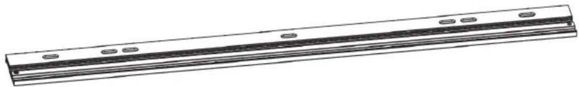
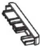
Pure technical line drawing of a rectangular mechanical component with evenly spaced holes and grooves (no text or symbols)A Wall Mount (x1)

natural_image
Technical line drawing of a mechanical component with no visible text or symbolsB TV Bracket (x2)
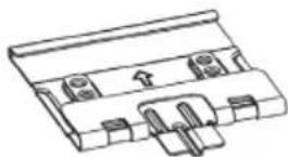
C Wall Bracket (x2)
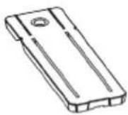
D Kickstand (x1)
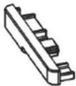
E Left Endcap (x1)
F Right Endcap (x1)

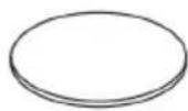
G Spirit Level (x1)

H Foam Pad (x4)
I Foam Pad (x4)

J Allen Key (3mm)
(x1)

M-A M6x14 Screw (x4)
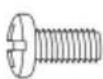
M-B M8x16 Screw (x4)
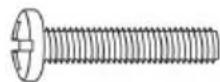
M-C M6x30 Screw (x4)
M-D M8x35 Screw (x4)
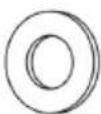
M-E D8 Washer (x4)
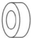
M-F Spacer (x4)

M-G Spacer (x4)
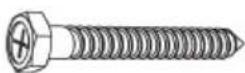
W-A ST6.3x55 Screw (x4)
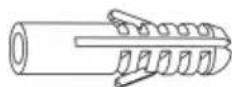
W-B Wall Anchors (x4)

W-C D6 Washer (x4)
ASSEMBLY
Tools Required

Stud finder

Pen/pencil

Drill & Drill Bit
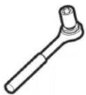
Ratchet & Sockets
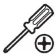
Phillips head
screwdriver
Step 1:
Separate the wall mount (A) into (A2) & (A1).

text_image
A A1 A2Step 2:
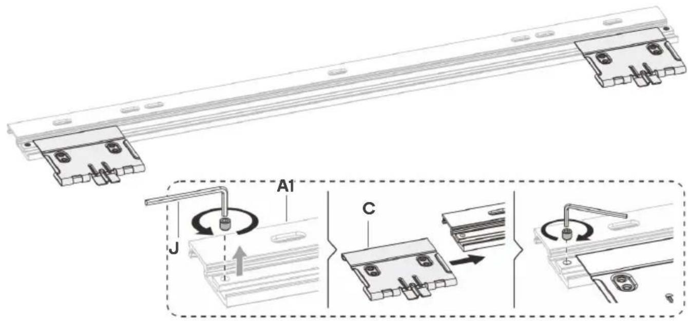
- Remove the fasteners from the end of the wall mount (A) and slide the 2 wall brackets (C) into the channel. Replace the fasteners.
- Attach the spirit level (G) to the top of the wall mount (A).
text_image
Technical diagram showing assembly steps of a mechanical component with labeled parts A1, C, and J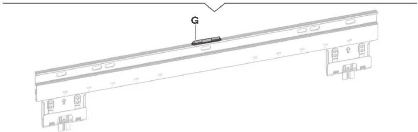
text_image
Technical diagram of a bridge structure with labeled components and directional arrows indicating movement or flow.Step 3:
Using a pencil and spirit level (G), mark the desired position for the mount on your wall, using the wall mount (A) as a template for the hole positions. Note: When using the spirit level, ensure the bubble is centred as per the image shown below.
If mounting on dry wall or plaster-board, use a stud finder first to check positions of wall studs and ensure the position is free from electrical wiring. Using a drill, create the pilot holes.
Drywall / plaster: Use a 4.5mm or 3/16" drill bit, drilling 55mm deep - 2 holes
Masonry / concrete: Use a 10mm or 3/8'' drill bit, drilling 60mm deep - 3 holes

text_image
55mm (2.2") Ø4.5mm (Ø3/16") 60mm (2.4") Ø10mm (Ø3/8")Step 4:
Drywall / plaster: Attach the wall mount (A) to the wall using the 2 ST6.3x55 screws (W-A) and D6 washers (W-C). Ensure a 5mm excess is left between the head of the screw and the wall surface. Do not use wall anchors.
Masonry / concrete: Insert wall anchors (W-B) into all 3 drilled holes. Attach the wall mount (A) to the wall using the 3 ST6.3x55 screws (W-A) and D6 washers (W-C). Ensure a 5mm excess is left between the head of the screw and the wall surface.

text_image
W-C W-A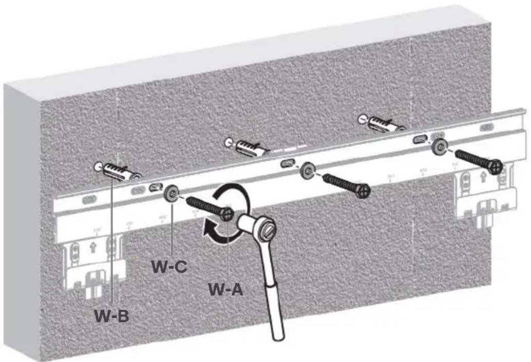
text_image
W-B W-C W-AStep 5:
- Set the distance of the wall brackets (C) depending on the size of your TV.
- Replace part (A2) back onto the wall mount (A) and attach the endcaps (E) & (F). to the ends of wall mount (A).
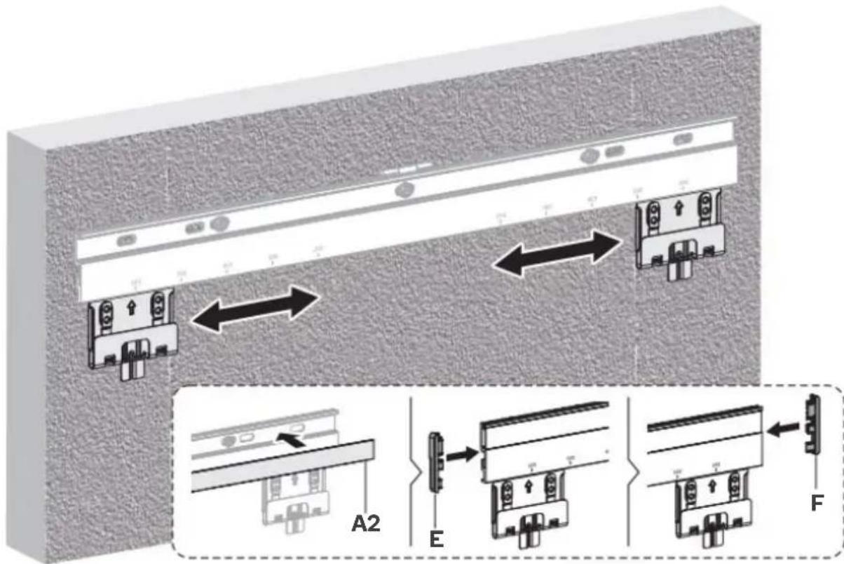
text_image
Technical diagram showing assembly of a device with labeled components A2, E, and F, including directional arrows indicating assembly or connection.Step 6:
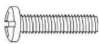
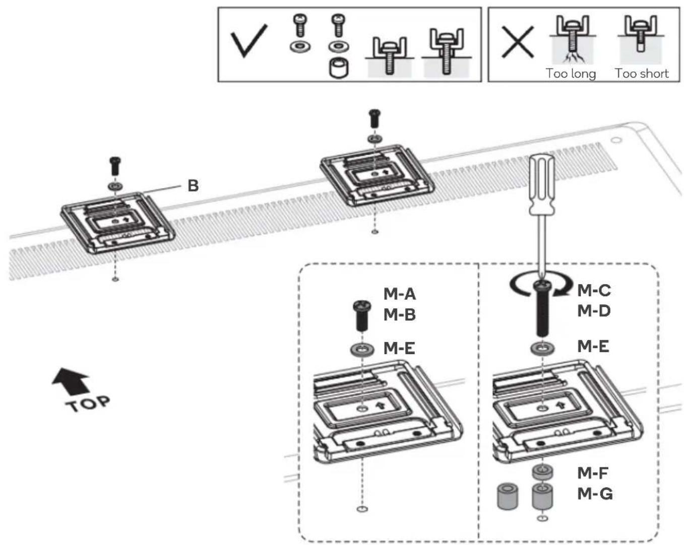
Align the brackets (B) with your TV's VESA holes and secure using supplied screws ("M-" set), Washer (M-E) and spacers (M-F, M-G) depending on required length.
text_image
B TOP M-A M-B M-E M-C M-D M-E M-F M-GStep 7:
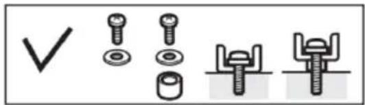
If a corresponding hole is available on your TV, attach the kickstand (D) and secure using supplied screws ("M-" set), Washer (M-E) and spacers (M-F, M-G) depending on required length.
text_image
Diagram showing four types of bolt and nut assembly symbols: checkmark, two screws, one nut, and three bolts with a base.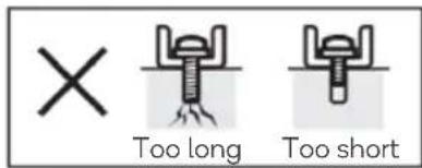
text_image
Too long Too short
text_image
TOP M-A M-B M-E D M-C M-D M-E M-F M-GStep 8:
Attach the appropriate EVA pads (H) & (I) to the rear of the TV to fill the wall-to-TV gap.
text_image
I HStep 9:
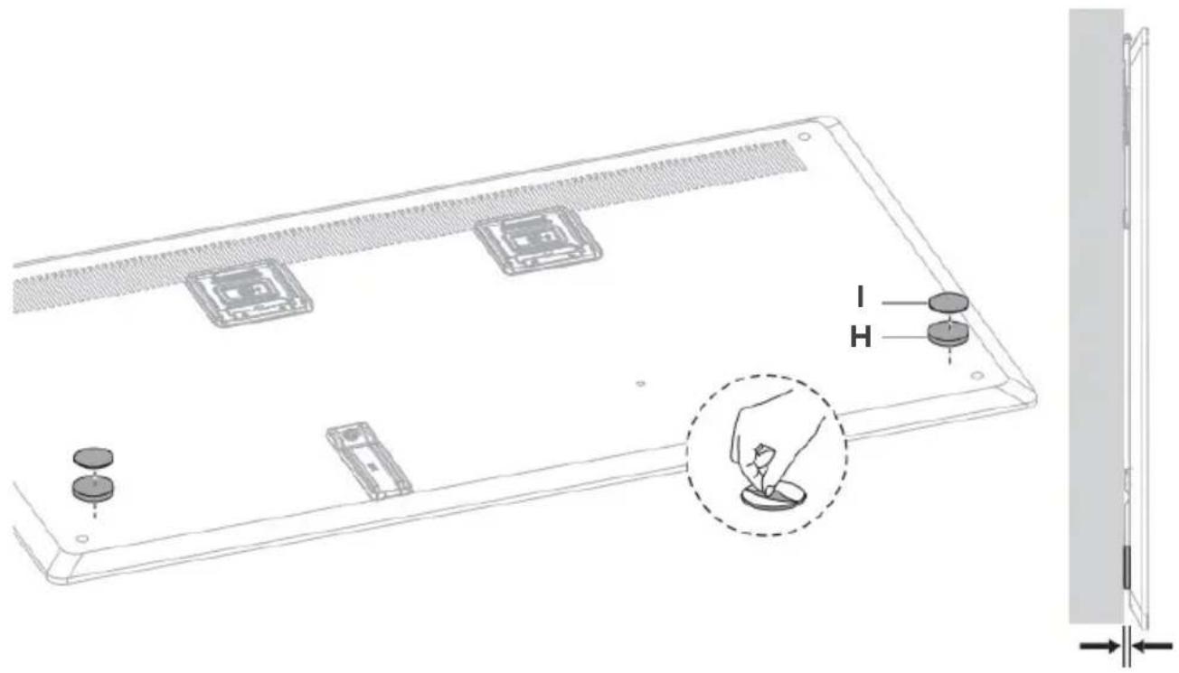
- Carefully hook the TV with brackets and optional kickstand installed onto the wall mount. 2 people should carry the TV to prevent damage. Note: Ensure the hooks on the TV brackets are completely seated in the wall brackets.
• Gently lower TV so it is flush with wall and the foam pads are contacting the wall.

text_image
Diagram illustrating a device installation procedure with labeled components and directional arrows, including a person viewing the screen.
natural_image
Diagram showing a door frame with an arrow indicating direction, alongside a close-up of the door structure (no text or symbols present)Step 10: Removing the TV from the Wall Mount
To remove, using the assistance of another person, carefully lift the TV upwards and unhook TV brackets from the wall brackets.
IMPORTANT: Do not attempt to remove the TV by yourself

NOTES
Need more information?
We hope that this user guide has given you the assistance needed for a simple set-up.
For the most up-to-date guide for your product, as well as any additional assistance you may require, head online to help.kogan.com
kogan.com