KAMMTGASTPA - Vacuum Cleaner Kogan - Free user manual and instructions
Find the device manual for free KAMMTGASTPA Kogan in PDF.

User questions about KAMMTGASTPA Kogan
0 question about this device. Answer the ones you know or ask your own.
Ask a new question about this device
Download the instructions for your Vacuum Cleaner in PDF format for free! Find your manual KAMMTGASTPA - Kogan and take your electronic device back in hand. On this page are published all the documents necessary for the use of your device. KAMMTGASTPA by Kogan.
USER MANUAL KAMMTGASTPA Kogan
natural_image
Technical line drawing of a mechanical linkage assembly (no text or symbols)FULL MOTION GAS SPRING TRIPLE MONITOR ARM
(SUITABLE FOR MONITORS 17-27")
KAMMTGASTPA
SAFETY & WARNINGS
WARNING: Incorrect Installation may cause serious personal injury, death and damage of property. Read the following information before installation.
Read the entire user guide before you commence installation and assembly. If you do not understand these directions or if you have any doubts about the safety of the installation, contact a qualified technician.
CAUTION: Use with products heavier than the rated weights indicated may result in instability causing possible injury.
- Ensure that you have received all parts according to the component checklist prior to installation. If any parts are missing or faulty, contact help.Kogan.com for support.
- Closely follow the assembly instructions. Improper installation may result in property damage or serious personal injury.
- Do not use this product for any purpose that is not explicitly specified in this guide.
- Do not exceed the weight capacity.
-
Serious or fatal injuries can occur from tip over. To prevent tip over:
-
Never allow children to climb, stand, hang or play on any part or monitor or stand.
-
Use tip over restraint or anchor stand to wall.
-
Use the mounting screws provided and DO NOT OVER TIGHTEN mounting screws.
- This product contains small items that could be a choking hazard if swallowed. Keep these items away from children.
- This product is intended for indoor use only. Using this product outdoors could lead to product failure and personal injury.
- Use of tip-over restraints may reduce but not eliminate the risk of tip-over.
- Small parts are not suitable for children under 3 years. Adult supervision is required.
IMPORTANT: Ensure that you have received all parts according to the component checklist prior to installation. If any parts are missing or faulty, contact your place of purchase for a replacement.
MAINTENANCE: Check that the product is secure and safe use at regular intervals (at least every three months).

text_image
75x75/100x100 MAX 27" 8kg x3 RATEDCOMPONENTS

A Pole

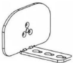
natural_image
Technical line drawing of a mechanical component with mounting holes and internal ribs (no text or symbols)D Monitor arm
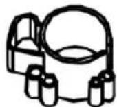
G Wire clip

J Head sleeve

G1 M4x30 Bolt (x12)
H2 Small spacer (x12)
D1 Cable case (x2)
B Clamp
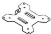
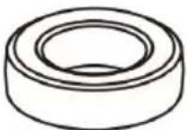
E VESA plate (x3)
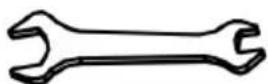
H Spanner
Z1 Cable case (x4)
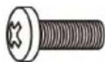
G2 M4x12 Bolt (x12)

M Washer (x12)
natural_image
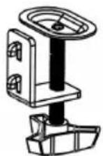
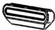
Line drawing of a mechanical component with a lid and mounting base (no text or symbols)C Clamp support
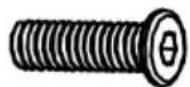
F M5x18 Bolt (x3)

natural_image
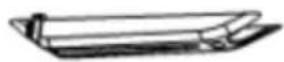
Pure geometric lines forming a stepped L-shape (no text or symbols)I Allen key (x4)
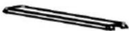
Z2 Cable case cap (x4)

H1 Big spacer (x12)
M4x12 Bolt
INSTALLATION
Step 1: Install the Clamp and Pole on a Desk
Option A: Clamp installation
- Connect clamp support (C) and pole (A) with x3 M5x18 Bolts (F) and tighten it with Allen key (I).
- Connect clamp (B) and clamp support (C) with pre-positioned screws and choose proper hole sit according to the thickness of desk. Tighten the plastic knob to fix the clamp.

text_image
A F C >42mm COption B: Grommet installation
- Connect grommet support (C) and pole (A) with x3 M5x18 bolt (F) and tighten it with Allen key (I). Use clamp support (C) into desk hole with diameter greater than 42mm.
- Connect grommet (B) and grommet support (C), choose proper hole site according to the thickness of desk. Tighten the plastic knob to clamp it on the table.

text_image
A F C >42mm CStep 2:
Install the pole and the main mount
- Place wire clip (G) on pole (A).
- Place swivel arm (D) on pole (A). Tighten screw with Allen Key (I) at proper position.

text_image
Technical diagram of a mechanical assembly with labeled components A, D, E, I, and GStep 3:
Install monitor, VESA plate and main mount.
Warning: Make sure the screws are tightened.

Warning: Make sure the screws are tightened.
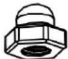
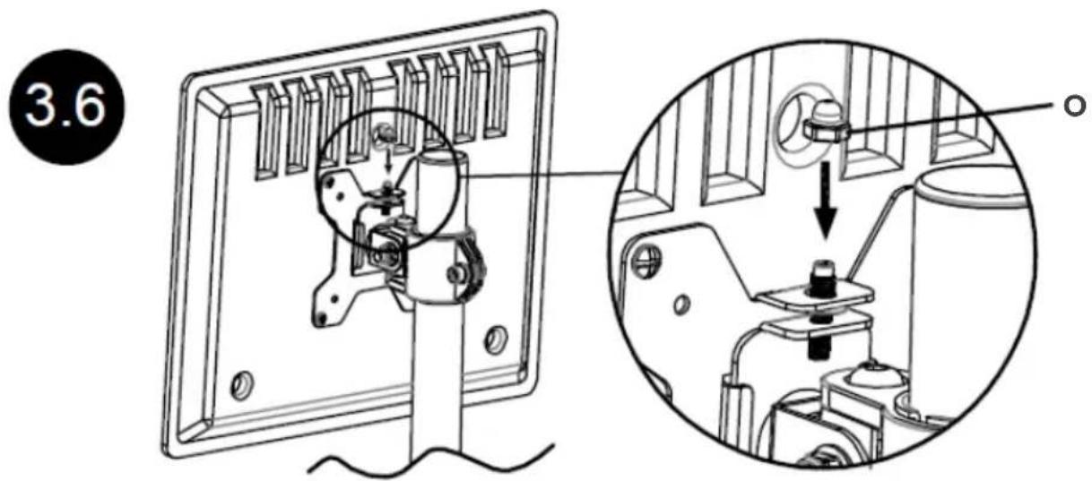
Drive nut (O) in plate into screw hole of head sleeve
text_image
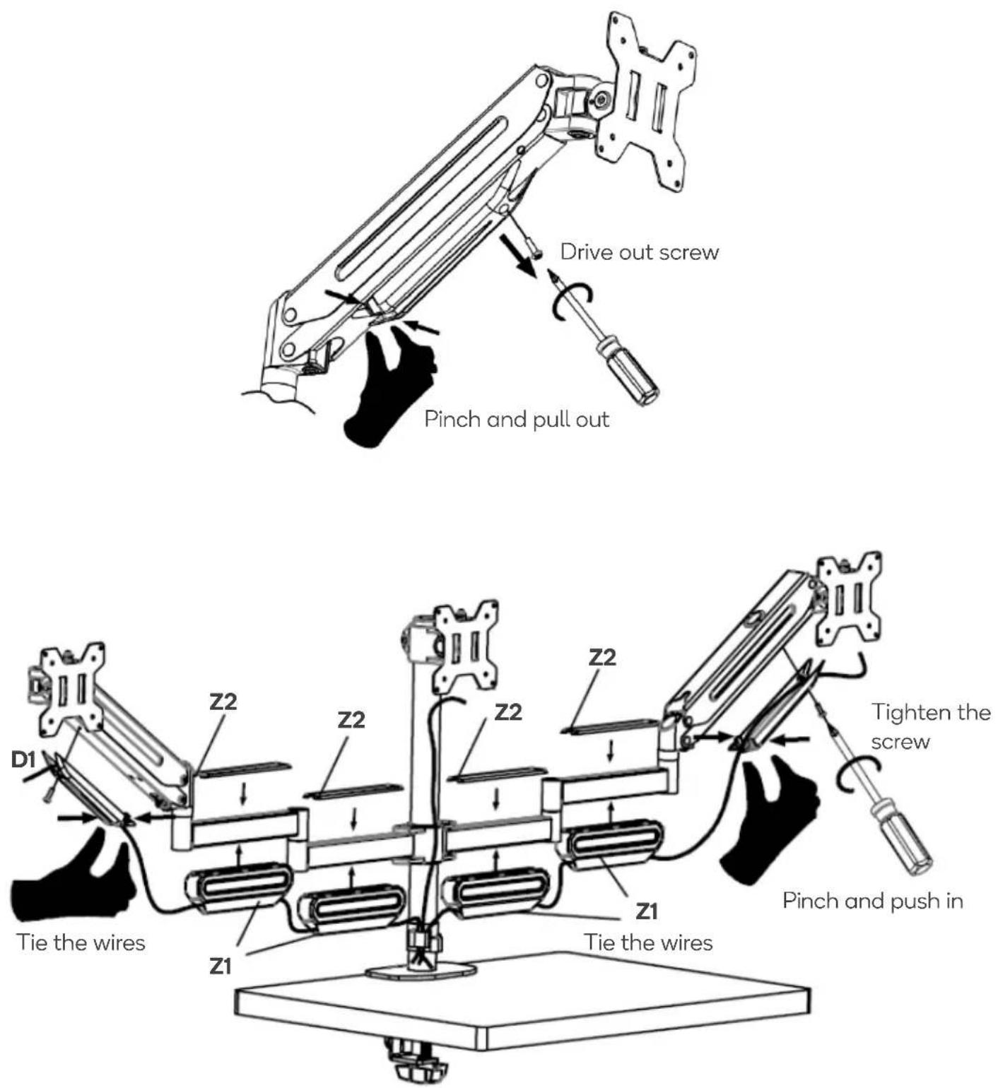
3.6Step 4: Cable management
text_image
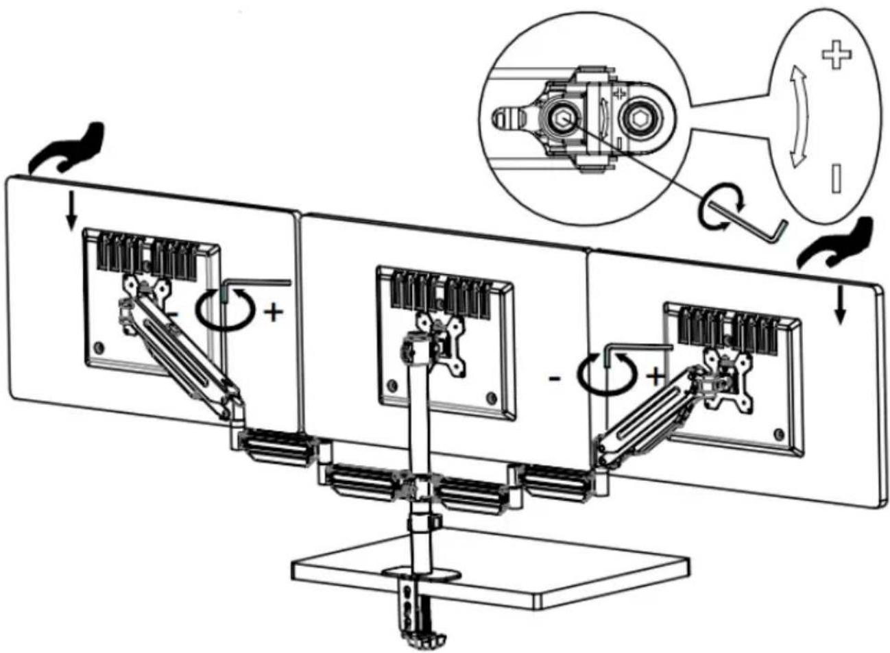
Drive out screw Pinch and pull out Tie the wires D1 Z2 Z2 Z2 Z2 Z1 Tie the wires Z1 Tighten the screw Pinch and push inStep 5: Adjustment of torque force
- Once the monitor is hung on the mount, it will remain at any height without needing adjustment.
- If the monitor bounces after being hung on the mount, press down on the monitor with one hand to ensure the arm is horizontal. Use an S5 Allen key with your other hand to turn the screw in the “-” direction gradually until the monitor stays at any desired height.
- If the monitor falls after being hung on the mount, raise the monitor with one hand to ensure the arm is horizontal. Use an S5 Allen key with your other hand to turn the screw in the “+” direction gradually until the monitor stays at any desired height.
WARNING: Ensure the weight of the monitor in under the load capacity.
+ Increase torque force
- Decrease torque force
text_image
Technical diagram illustrating mechanical assembly with labeled components and directional arrows, including a magnified inset showing rotational motion.WARNING: Make sure the monitor is hung on the mount before adjustment. Make sure the weight of monitor is within the capacity.
Adjust Torque Force

natural_image
Simple black curved arrow with a plus sign at the end, no text or symbols presentDecrease Increase

natural_image
Silhouette of a person holding a knife with motion arrows indicating movement (no text or symbols)WARNING: The arm is under tension. Be extremely careful when removing the monitor, as the mount may spring up quickly.
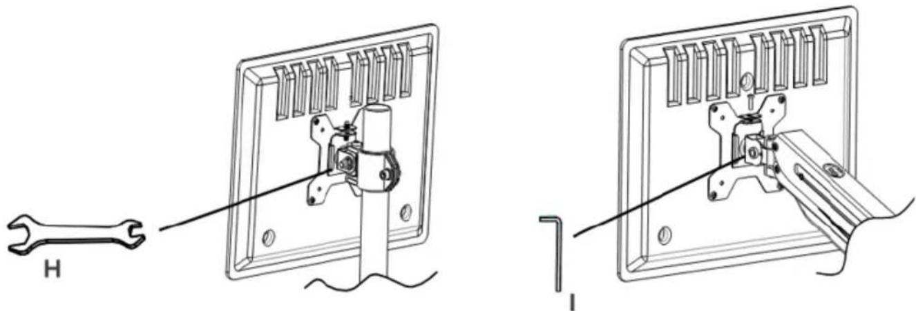
Step 6: Monitor Adjustments
If the monitors are not in your desired positions, use the Allen key (I) or Spanner (H) to tighten the screws as shown.
text_image
Technical diagram showing a wrench tool interacting with a mechanical device, with labeled parts H and I.Need more information?
We hope that this user guide has given you the assistance needed for a simple set-up.
For the most up-to-date guide for your product, as well as any additional assistance you may require, head online to help.kogan.com
kogan.com