AT-PRO5-MX810 - Switch Atlona - Free user manual and instructions
Find the device manual for free AT-PRO5-MX810 Atlona in PDF.

User questions about AT-PRO5-MX810 Atlona
0 question about this device. Answer the ones you know or ask your own.
Ask a new question about this device
Download the instructions for your Switch in PDF format for free! Find your manual AT-PRO5-MX810 - Atlona and take your electronic device back in hand. On this page are published all the documents necessary for the use of your device. AT-PRO5-MX810 by Atlona.
USER MANUAL AT-PRO5-MX810 Atlona
with SDVoE Extension Outputs
text_image
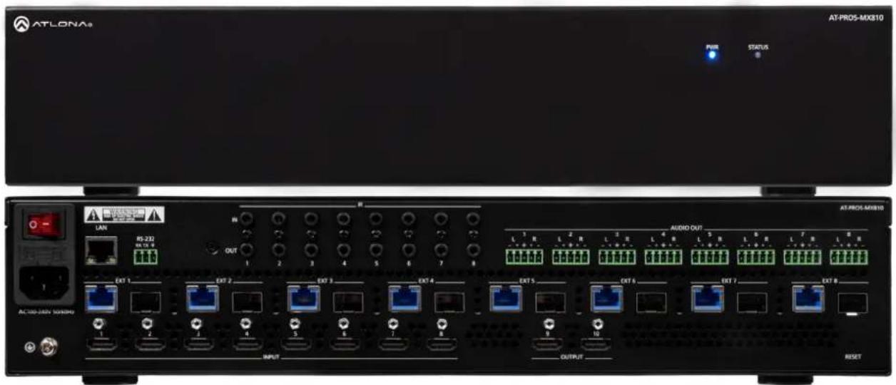
ATLONA PWR STATUS AT-PRO5-MX810 LAN RS-232 RS 12.6 OUT 1 2 3 4 5 6 7 8 AUDIO OUT L 1 R L 2 R L 3 R L 4 R L 5 R L 6 R L 7 R L 8 AC:300-DAV SOND#Y EXT 1 EXT 2 EXT 3 EXT 4 EXT 5 EXT 6 EXT 7 EXT 8 1 2 3 4 5 6 7 8 OUTPUT RESETAT-PRO5-MX810
Atlona Manuals
Switchers
Version Information
| Version Release Date Notes | |
| 1 Jan 2025 Initial release |
Sales, Marketing, and Customer Support
Main Office
Atlona Incorporated
70 Daggett Drive
San Jose, CA 95134
United States
Office: +1.408.962.0515
Sales and Customer Service Hours
Monday - Friday: 6:00 a.m. - 4:30 p.m. (PST)
https://atlona.com/
International Headquarters
Atlona International AG
Tödistrasse 18
8002 Zürich
Switzerland
Office: +41.43.508.4321
Sales and Customer Service Hours
Monday - Friday: 09:00 - 17:00 (UTC +1)
Operating Notes

IMPORTANT: Visit https://www.atlona.com/product/AT-PRO5-MX810 for the latest firmware updates and User Manual.
Warranty

To view the product warranty, use the following link or QR code:
https://atlona.com/warranty/.
Safety and Certification
CAUTION
RISK OF ELECTRIC SHOCK
DO NOT OPEN
CAUTION: TO REDUCT THE RISK OF
ELECTRIC SHOCK
DO NOT OPEN ENCLOSURE OR EXPOSE
TO RAIN OR MOISTURE
NO USER-SERVICEABLE PARTS
INSIDE REFER SERVICING TO
QUALIFIED SERVICE PERSONNEL.

The exclamation point within an equilateral triangle is intended to alert the user to the presence of important operating and maintenance instructions in the literature accompanying the product.

The information bubble is intended to alert the user to helpful or optional operational instructions in the literature accompanying the product.
- Read these instructions.
- Keep these instructions.
- Heed all warnings.
- Follow all instructions.
- Do not use this product near water.
- Clean only with a dry cloth.
- Do not block any ventilation openings. Install in accordance with the manufacturer's instructions.
-
Do not install or place this product near any heat sources such as radiators, heat registers, stoves, or other apparatus (including amplifiers) that produce heat.
-
Do not defeat the safety purpose of a polarized or grounding-type plug. A polarized plug has two blades with one wider than the other. A grounding type plug has two blades and a third grounding prong. The wide blade or the third prong are provided for your safety. If the provided plug does not fit into your outlet, consult an electrician for replacement of the obsolete outlet.
- Protect the power cord from being walked on or pinched particularly at plugs, convenience receptacles, and the point where they exit from the product.
- Only use attachments/accessories specified by Atlona.
- To reduce the risk of electric shock and/or damage to this product, never handle or touch this unit or power cord if your hands are wet or damp. Do not expose this product to rain or moisture.
- Unplug this product during lightning storms or when unused for long periods of time.
- Refer all servicing to qualified service personnel. Servicing is required when the product has been damaged in any way, such as power-supply cord or plug is damaged, liquid has been spilled or objects have fallen into the product, the product has been exposed to rain or moisture, does not operate normally, or has been dropped.
CE
FC
cULus
CCC
√
[RECYC CIRCUM SYMBOL]

FCC Compliance
FCC Compliance and Advisory Statement: This hardware device complies with Part 15 of the FCC rules. Operation is subject to the following two conditions: 1) this device may not cause harmful interference, and 2) this device must accept any interference received including interference that may cause undesired operation. This equipment has been tested and found to comply with the limits for a Class A digital device, pursuant to Part 15 of the FCC Rules. These limits are designed to provide reasonable protection against harmful interference in a commercial installation. This equipment generates, uses, and can radiate radio frequency energy and, if not installed or used in accordance with the instructions, may cause harmful interference to radio communications. However there is no guarantee that interference will not occur in a particular installation. If this equipment does cause harmful interference to radio or television reception, which can be determined by turning the equipment off and on, the user is encouraged to try to correct the interference by one or more of the following measures: 1) reorient or relocate the receiving antenna; 2) increase the separation between the equipment and the receiver; 3) connect the equipment to an outlet on a circuit different from that to which the receiver is connected; 4) consult the dealer or an experienced radio/TV technician for help. Any changes or modifications not expressly approved by the party responsible for compliance could void the user's authority to operate the equipment. Where shielded interface cables have been provided with the product or specified additional components or accessories elsewhere defined to be used with the installation of the product, they must be used in order to ensure compliance with FCC regulations.
Copyright, Trademark, and Registration
© 2025 Atlona Inc. All rights reserved. "Atlona" and the Atlona logo are registered trademarks of Atlona Inc. Pricing, specifications and availability subject to change without notice. Actual products, product images, and online product images may vary from images shown here.

The terms HDMI, HDMI High-Definition Multimedia Interface, HDMI trade dress and the HDMI Logos are trademarks or registered trademarks of HDMI Licensing Administrator, Inc.
Dolby, Dolby Atmos, and the double-D symbol are registered trademarks of Dolby Laboratories Licensing Corporation.
For DTS patents, see http://patents.dts.com. Manufactured under license from DTS, Inc. DTS, the Symbol, DTS and the Symbol together, and Digital Surround are registered trademarks and/or trademarks of DTS, Inc. in the United States and/or other countries. © DTS, Inc. All Rights Reserved.
All other trademark(s), copyright(s), and registered technologies mentioned in this document are the properties of their respective owner(s).
Table of Contents
Introduction 7
Features 7
Package Contents 7
Panel Description 8
Front Panel 8
Rear Panel 9
Installation 10
Connection Instructions 10
Connection Diagram 11
Device Operation 12
LED Indicators 12
Logging in to the Web Server 13
Login Registration 13
Logging in after Registration 14
System Settings 15
Obtaining System Information 15
Changing the Administrator Password 16
Enabling / Disabling SSH and Telnet Proxy 17
Enabling / Disabling System Standby Mode 18
Performing a Factory Reset 19
Rebooting the System 21
Network Configuration 22
Setting the IP Mode 22
IEEE 802.1x Authentication 24
Setting the Host Name 27
System Time 28
Setting the Time Zone 28
Assigning an NTP Server 29
Setting the System Time 30
Matrix Switching 31
Video Routing 31
Manual Audio Routing 32
Follow Video 32
Saving / Loading Switching Presets 33
Activating a Preset 33
Matrix Configuration 34
Changing the Input Name 34
Selecting an EDID 35
HDCP Content 36
Changing the Output Name 37
Changing the Display Mode 38
EDID Management 40
EDID Presets 41
Creating a Custom EDID 42
Copying a Downstream EDID 43
Video Walls 44
Creating a Video Wall 44
Saving a Video Wall Preset 46
Device Control 47
RS-232 Control Settings 47
CEC Display Control 48
Table of Contents
System Maintenance 50
Updating the Firmware 50
Downloading Log Files 50
API Testing 51
Power Saving 52
Appendix
Specifications 53
53
Introduction
The Atlona AT-PRO5-MX810 is an 8x10 matrix switcher with eight HDMI ^ inputs, two HDMI outputs, and eight AV extension outputs with SDVoE ^ 10GbE connectivity for ultra-high definition video and audio delivery to an Atlona AT-PRO5-101-SC-RX or AT-PRO5-101-RX receiver. Part of the PRO5 Series, this matrix switcher is HDCP 2.3 compliant, and supports 4K/60 4:4:4 and HDR at HDMI data rates up to 18 Gbps. Each SDVoE extension output includes an RJ45 port, and an SFP+ cage for copper or fiber optic connectivity to transmit video, embedded audio, Gigabit Ethernet, and RS-232 and IR control signals to the receiver. The RJ45 port allows extension up to 330 feet (100 meters) over CAT6a UTP cable, along with PoE for powering the receiver, while the SFP+ cage can be used with a compatible fiber optic module to extend from 38 meters up to 10 kilometers over fiber optic cable. Video processing is available in the PRO5-101-SC-RX scaling receivers, including 4K video upscaling and downscaling with frame rate conversion, and video wall processing. This HDMI to SDVoE matrix switcher is equipped with a comprehensive host of audio and control system integration features, making it ideal for a wide range of commercial applications requiring multi-zone AV distribution with long-distance signal extension.
Features
- 8x10 HDMI matrix switcher with HDMI and SDVoE ^® extension outputs
• High-performance, SDVoE-based, point-to-point AV transmission - Eight SDVoE extension outputs, each with copper or fiber optic connectivity (1)
- 4K/UHD capability @ 60 Hz with 4:4:4 chroma sampling, plus support for HDR formats.
- HDCP 2.3 compliant
• Power over Ethernet (PoE) for remotely powering AT-PRO5-101-SC-RX and AT-PRO5-101-RX receivers
• High-performance video processing available with AT-PRO5-101-SC-RX scaling receivers (2)
• Video wall processing available with AT-PRO5-101-SC-RX scaling receivers - Flexible, independent audio matrix switcher
• Multi-channel audio compliant
• EDID management
• HDCP 2.3 management - Provides HDMI signal regeneration for source devices
- Intuitive GUI-based configuration using integrated web server
• TCP/IP and RS-232 control - TCP proxy streamlines control system integration
- Independent CEC display control to each output
- Comprehensive IR control management for sources and displays
- Easy to configure and manage with Velocity Device Manager
- Rack mountable 2U, full-rack width enclosure
Package Contents
1 x AT-PRO5-MX810
1 x 3-pin captive screw connector
8 x 5-pin captive screw connectors
1 x AC power cord
1 x Insert w/ QR code
(1) Signals can be transported over copper or fiber, but not both simultaneously.
Panel Description
Front Panel
text_image
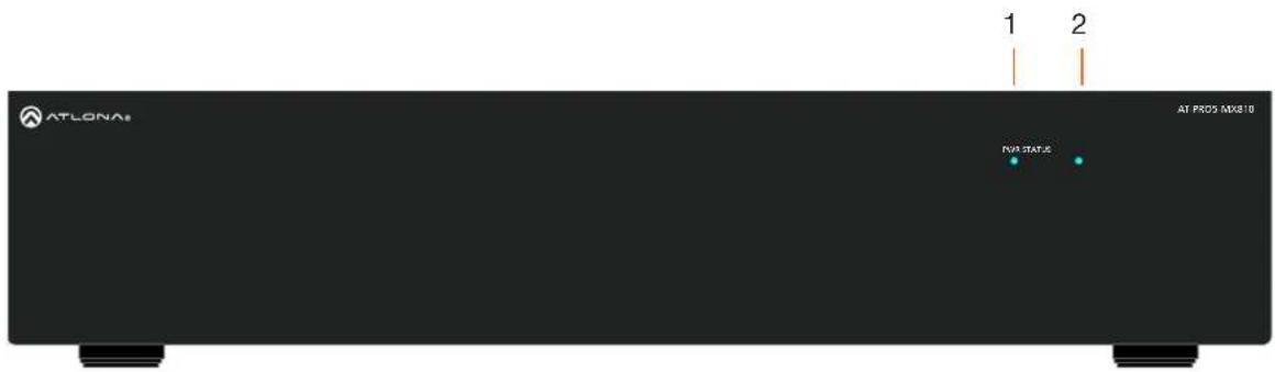
ATLONA 1 2 AT PROS MX810 PWR STATUS1 PWR
LED will be red while the unit is booting and blue when operating normally. Refer to LED Indicators (page 12) for more information.
2 STATUS
LED will be blue when the unit is operating normally. Refer to LED Indicators (page 12) for more information.
Rear Panel
text_image
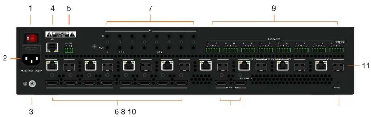
1 4 5 7 9 2 AC 100/300/100/100/ 3 6 8 10 11 L R L R L R L R L R L R L R UST UST UST UST UST UST UST UST UST UST UST UST UST UST UST UST UST UST UST UST UST UST UST UST UST UST UST UST UST UST UST UST UST UST UST UST UST UST UST UST UST UST UST UST UST UST UST UST UST UST UST UST UST UST UST UST UST UST UST UST UST UST UST UST UST UST UST UST UST UST UST UST UST UST UST UST UST UST UST UST UST UST UST UST UST UST UST1 Power Switch
Turns the AT-PRO5-MX810 on or off. Press the side of the switch labeled "I" to power-on the unit. Press the side of the switch labeled "O" to power-off the unit.
2 IEC Connector
Connect the included power cord from this power receptacle to an available grounded wall outlet.
3 Chassis Ground
Provides a common return path for electric current and a safety feature to prevent electric shock.
4 LAN
Connect an Ethernet cable from this port to the network.
5 RS-232
Connect the included 3-pin captive screw connector to this port.
6 INPUT
Connect an HDMI cable from each of these ports to a HD/UHD source.
7 IR
This bank of ports provide both IR inputs and outputs. Connect 3.5 mm jacks to these ports.
8 OUTPUT
Connect an HDMI cable from each of these ports to a display, such as a confidence monitor.
9 AUDIO OUT
Connect the included 5-pin captive screw connectors from these port to an amplifier.
10 RESET
Press this button to perform a factory-reset of the AT-PRO5-MX810.
11 EXT 1 - EXT 8
Connect these outputs to the AT-PRO5-101-SC-RX scaling receiver or AT-PRO5-101-RX receiver. RJ45 ports provide extension up to 330 feet (100 meters) over CAT6A/7 cable along with Power over Ethernet (PoE). SFP+ cage can be used with compatible fiber optic transceiver modules to extend from 38 meters up to 10 kilometers over fiber optic cable.
Installation
Connection Instructions
- Connect an HDMI cable from each source to these INPUT ports.
-
Connect an AT-PRO5-101-RX or AT-PRO5-101-SC-RX receiver to the EXT 1 - EXT 8 ports. Note that the RJ45 and SFP+ ports cannot be used at the same time to extend AV sources.
-
RJ45 ports: connect CAT6a/7 cabling up to 330 feet (100 meters) to AT-PRO5-101-SC-RX scaling receivers or AT-PRO5-101-RX receivers.
-
SFP+ cage: connect compatible fiber optic transceiver modules to extend from 38 meters (125 feet) up to 10 kilometers (6.2 miles) over fiber optic cable. Refer to Table 1.1 for a listing of compatible transceivers.
-
Connect an HDMI cable from the OUTPUT ports to displays, such as a confidence monitors.
-
Connect an Ethernet cable from the LAN port to the Local Area Network (LAN). This step will be required in order to access the built-in web server.
-
Connect the included 3-pin captive screw connector from the RS-232 port to a control system.
-
Connect a 3.5 mm jack from the control system to the IR IN ports. Connect IR emitters, such as the AT-VCC-IR-EMT, from the IR OUT ports to controlled devices.
-
Connect the included 5-pin captive screw connectors from these AUDIO OUT ports to an amplifier.
-
Connect the chassis ground to a stable and reliable grounding point that safely conducts stray or fault currents away from the device.
-
Connect the included AC power cord from the AC 100-240V 50/60 Hz power receptacle to an available AC electrical outlet.
-
Press the side of the switch labeled "I" to power-on the AT-PRO5-MX810.
Table 1.1 - Compatible transceivers
| Manufacturer | Product |
| Atlona | AT-SFP-PLUS-10GE-SR |
| FS | FS SFP+ 10GB 850nm LC |
| Ubiquiti | UACC-OM-MM-10G-D-2 |
| Proline | EW3D0000710-PRO |
| StarTech | 455883B21ST |
text_image
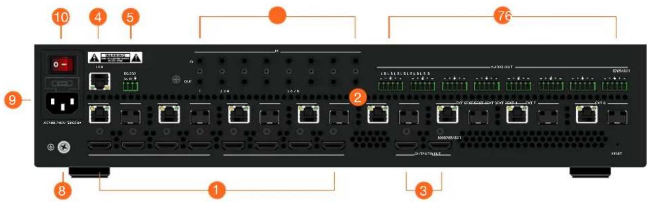
10 4 5 76 9 1 8 1 3Installation
Connection Diagram
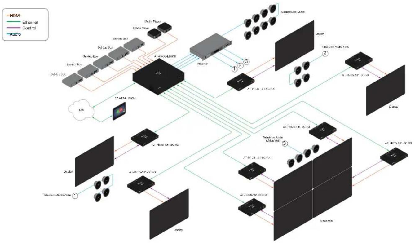
flowchart
graph TD
    A["AT-PROS-101-SC-RX"] --> B["Display"]
    A --> C["Video Wall"]
    B --> D["AT-PROS-101-SC-RX"]
    C --> E["AT-PROS-101-SC-RX"]
    D --> F["Display"]
    D --> G["Video Wall"]
    F --> H["AT-PROS-101-SC-RX"]
    G --> I["AT-PROS-101-SC-RX"]
    H --> J["AT-VTP8-1000V"]
    I --> K["AT-PROS-101-SC-RX"]
    J --> L["AT-VTP8-1000V"]
    K --> M["AT-PROS-101-SC-RX"]
    L --> N["AT-PROS-101-SC-RX"]
    M --> O["Audio Box"]
    N --> P["Audio Box"]
    O --> Q["Media Player"]
    P --> R["Media Player"]
    Q --> S["Network"]
    R --> T["Network"]
    S --> U["Network"]
    T --> V["Background Music"]
    U --> V
    V --> W["Display"]
    V --> X["Twitterion Audio (Mide Wall)"]
    W --> Y["AT-PROS-101-SC-RX"]
    X --> Z["AT-PROS-101-SC-RX"]
Device Operation
LED Indicators
The LED indicators on both the front and rear of the unit provide basic information on the current status of the AT-PRO5-MX810.
| LED State Description | ||
| PWR Solid blue Matrix is powered and in normal operating mode. | ||
Logging in to the Web Server
Most of the AT-PRO5-MX810 operation is handled through the built-in web server. In order to access the web server, the IP address of the unit must be known.
Login Registration
Before the built-in web server can be accessed, a password must be created.
- Launch the desired web browser and enter the IP address of the AT-PRO5-MX810 in the address bar.
- The Login page will be displayed.
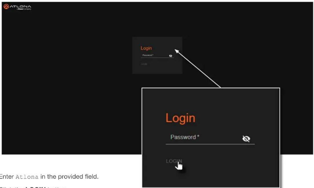
text_image
ATLONA Login Password * LOGIN Login Password * LOGIN Enter Atlona in the provided field.- Enter Atlona in the provided field.
- Click the LOGIN button.
- The Change Password screen will be displayed.

text_image
Change Password Please change your password to continue New Password * APPLYDevice Operation
- Enter the desired password in the Password field. By default, the password will be masked. To toggle between password masking and unmasking, click the 🔒 icon.

NOTE: Passwords can be 5 to 32 characters in length and can only contain letters, numbers, dashes, underscores, and periods. The password that is created is referred to as the Admin password. Additional users cannot be created or assigned. This password can be changed, if desired, from within the web server. Refer to Changing the Administrator Password (page 16) for more information.
- Click the Apply button to commit changes.
- The System > System page will be displayed.
Logging in after Registration
- Launch the desired web browser and enter the IP address of the AT-PRO5-MX810 in the address bar.
- Enter the correct password in the provided field.
- Click the LOGIN button.

text_image
Login Password * LOGIN- The System > System page will be displayed.
System Settings
The AT-PRO5-MX810 provides easy access to system configuration through the built-in web server, and is the recommended method to adjust network settings.
Obtaining System Information
- Log in to the web server.
- Click System in the side menu bar.
-
Click System in the top menu bar.
-
Locate the Info window group to obtain the IP address, MAC address, System Time, Temperature, and various other details about the AT-PRO5-MX810.
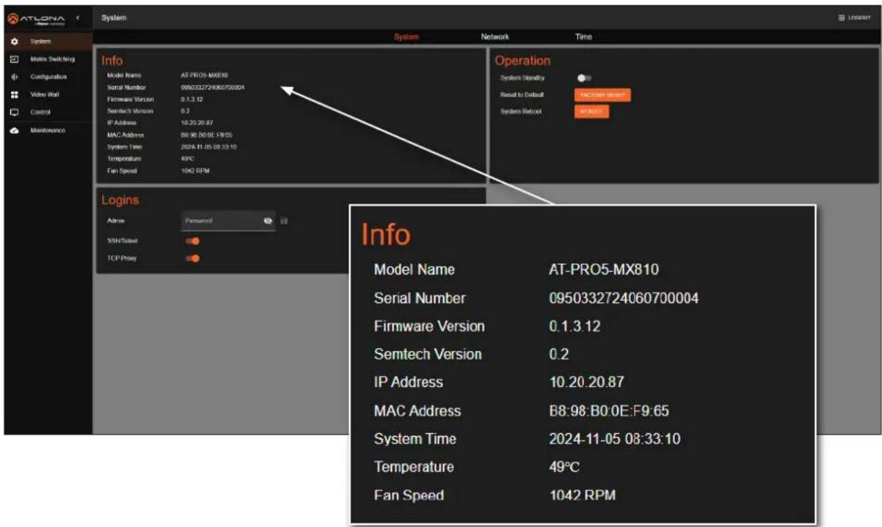
text_image
ATLONA System System Matera Switching Configuration Video Wall Control Maintenance Info Model Name AT-PRO5-M0810 Serial Number 0950332724060700004 Firmware Version 3.1.3.12 Semtech Version 0.3 IP Address 10.20.20.87 MAC Address 88.96 B0:0E:19:05 System Time 2024-11-05 08:33:10 Temperature 49°C Fan Speed 1042 RPM Logins Admin Password 55H/Tailout TCP Proxy Operation System Stability Reset to Default FACTORY RESET System Retout AT FREE Info Model Name AT-PRO5-MX810 Serial Number 0950332724060700004 Firmware Version 0.1.3.12 Semtech Version 0.2 IP Address 10.20.20.87 MAC Address B8:98:B0:0E:F9:65 System Time 2024-11-05 08:33:10 Temperature 49°C Fan Speed 1042 RPMDevice Operation
Changing the Administrator Password
- Log in to the web server.
- Click System in the side menu bar.
- Click System in the top menu bar.
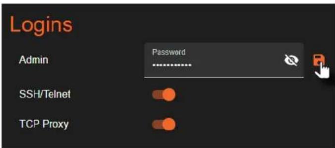
- Locate the Logins window group.
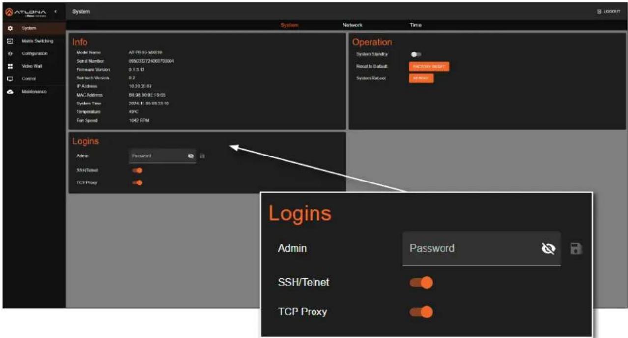
text_image
ATLONA System System Network Time Info Model Name AT-PI05-M0810 Serial Number 066032724060700804 Firmware Version 0.1.3.12 Switch Version 0.7 IP Address 10.20.20.67 MAC Address 58.98.80.8E-19.65 System Time 2024.11.05 08:33:10 Temperature 49°C Fan Speed 1042 RPM Operation System Standby Reset to Default: FACTORY RESET System Reset: Logins Admin Password SSH/Telnet TCP Proxy Logins Admin Password SSH/Telnet TCP Proxy- Enter the new password in the Admin field. By default, the password will be masked. To toggle between password masking and unmasking, click the icon.
text_image
Logins Admin Password SSH/Telnet TCP Proxy- Click the icon to commit changes.
Device Operation
Enabling / Disabling SSH and Telnet Proxy
- Log in to the web server.
- Click System in the side menu bar.
- Click System in the top menu bar.
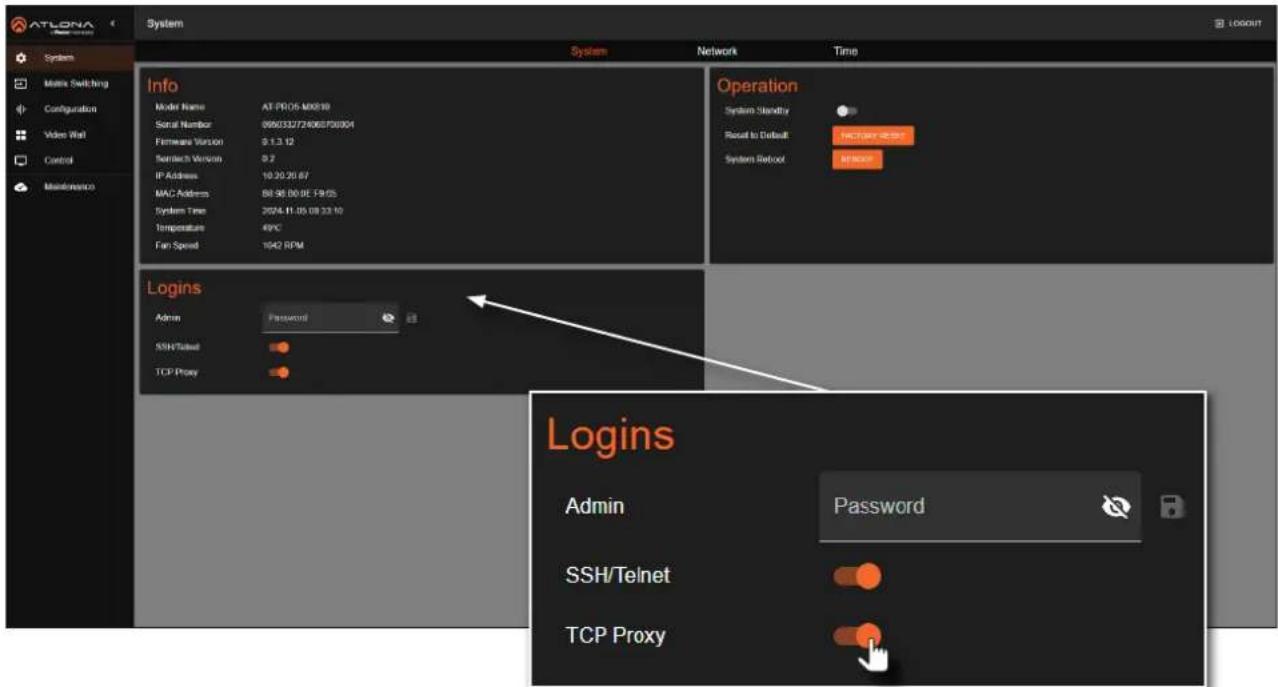
- Locate the Logins window group.
text_image
ATLONA System System Network Time Info Model Name AT-PRO5-M0819 Serial Number 066032724060700804 Firmware Version 9.1.3.12 Standard Version 0.7 IP Address 10.20.20.67 MAC Address 88.98.80.9E-19.65 System Time 2004-11-05 08:33:12 Temperature 49°C Fan Speed 1042 RPM Operation System Standby Reset to Default: Factory RESET System Retool: Logins Admin Password SSH/Telnet TCP Proxy Logins Admin Password SSH/Telnet TCP Proxy- Click the SSH/Telnet and/or TCP Proxy toggle switches to enable or disable each feature. When enabled, the toggle switches will be orange.
Device Operation
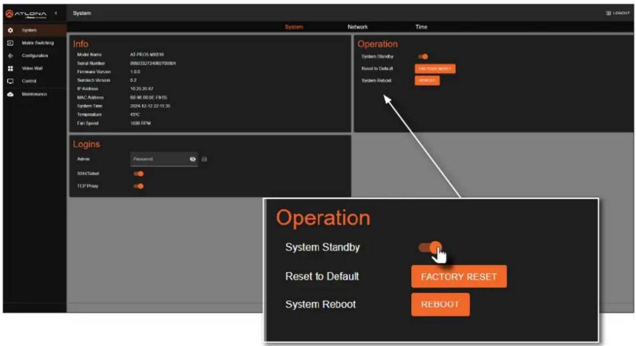
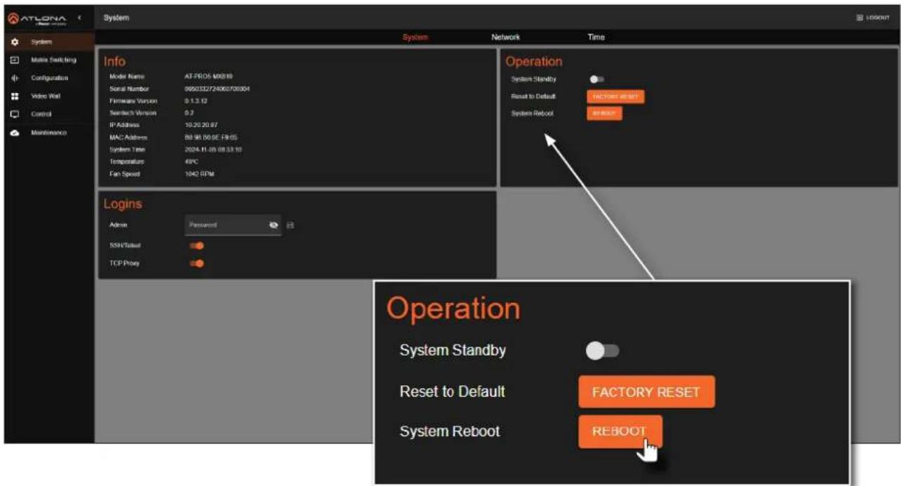
Enabling / Disabling System Standby Mode
When System Standby is enabled, the AT-PRO5-MX810 will disable A/V extension and other components to reduce the power consumption of the device.
- Log in to the web server.
- Click System in the side menu bar.
- Click System in the top menu bar.
- Locate the Operation window group.
text_image
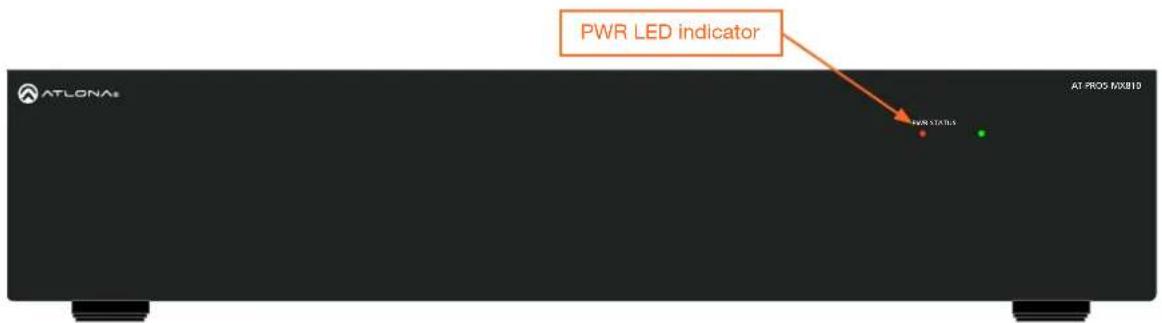
ATLONA System System Network Time Info Model Name AT-PRO5-M0518 Serial Number 090232724063700004 Firmware Version 1.00 Seamtech Version 0.2 IP Address 10.20.20.67 MAC Address 50.88.80.0E-F9.05 System Time 2024-12-12-22-11:35 Temperature 49°C Fan Speed 1636 RPM Operation System Standby Reset to Default FACTORY RESET System Reboot REBOOT Logins Admin Password SSH/Tailset TCP Proxy Operation System Standby Reset to Default FACTORY RESET System Reboot REBOOT- Click the System Standby toggle switch to enable or disable this feature. When enabled, the toggle switch will be orange and the PWR LED indicator, on the front panel, will be red.
text_image
PWR LED indicator ATLONA AT PROX MXB10Device Operation
Performing a Factory Reset
The AT-PRO5-MX810 can be restored to factory-default settings through the built-in web server or by pressing the RESET button on the rear panel. After performing a factory reset, the network IP mode will be set to DHCP mode and the login credentials will be reset. A new password will need to be created.
Using the Web Server
- Log in to the web server.
- Click System in the side menu bar.
- Click System in the top menu bar.
- Locate the Operation window group.

text_image
ATLONA System System Network Time Info Model Name AT PRO5 M0818 Serial Number 090032724060700004 Firmware Version 0.1.3.12 Switch Switch Version 0.2 IP Address 10.20.20.87 MAC Address 88.96.80.8E-19.65 System Time 2024-11-05 09:33:10 Temperature 49°C Fan Speed 1042 RPM Operation System Standby Reset to Default FACTORY RESET System Reboot REBOOT Logins Alarm Password SSN/Subset TCP Proxy Operation System Standby Reset to Default FACTORY RESET System Reboot REBOOT- Click the FACTORY RESET button.
- The following message will be displayed.

text_image
Factory Reset Are you sure you want to factory reset the system? CANCEL FACTORY RESET-
Click FACTORY RESET to continue with the process or click CANCEL to abort.
-
Once the unit has finished rebooting, repeat the procedure for creating a password. Refer to Login Registration (page 13) for more information.
Using the Rear Panel
- Locate the recessed RESET button on the rear panel.

text_image
WARNING 1.2KB 40.724 30.728 SUT 2.24 59.25 AC100-240V 150Hz RESET button OUTPUT-RESET A300-OUT 1K (R)LE 6: P8R10K 1K (R)LE 6: P8R10K 1K (R)LE 6: P8R10K SUT (R)LE/OUT 1: SUT 2: SUT 3: SUT 4: SUT SUT (R)LE/OUT 1: SUT 2: SUT 3: SUT 4: SUT OUTPUT-RESET RESET- Press and hold the RESET button for approximately 10 seconds, using the end of a paper clip or other small object.
- Release the RESET button.
- While the AT-PRO5-MX810 is rebooting, the STATUS LED indicator, on the front panel, will be blue and blink rapidly.

text_image
STATUS LED NOT STABLE AT-PROS-MX810 AT-LONA1- Once the unit has finished rebooting, repeat the procedure for creating a password. Refer to Login Registration (page 13) for more information.
Device Operation
Rebooting the System
The following procedure will reboot the AT-PRO5-MX810. All network and routing settings are preserved.
- Log in to the web server.
- Click System in the side menu bar.
- Click System in the top menu bar.
- Locate the Operation window group.
text_image
ATLONA System System Network Time Info Model Name: AT-PRO5 M0618 Serial Number: 0650332724060700304 Firmware Version: 0.1.3.12 Semtech Version: 0.3 IP Address: 10.20.20.87 MAC Address: 89.96.80.0E.FN.05 System Time: 2024.11.15 08:33:10 Temperature: 49°C Fan Speed: 104Ω RPM Operation System Standby Reset to Default FACTORY RESET System Reboot ReBOOT Logins Admin Password SSH Status TCP Proxy Operation System Standby Reset to Default FACTORY RESET System Reboot REBOOT- Click the REBOOT button.
- The following message will be displayed.

text_image
Reboot Are you sure you want to reboot the system? CANCEL REBOOT- Click REBOOT to continue with the process or click CANCEL to abort.
- Once the unit has finished rebooting, the Login screen will be displayed.
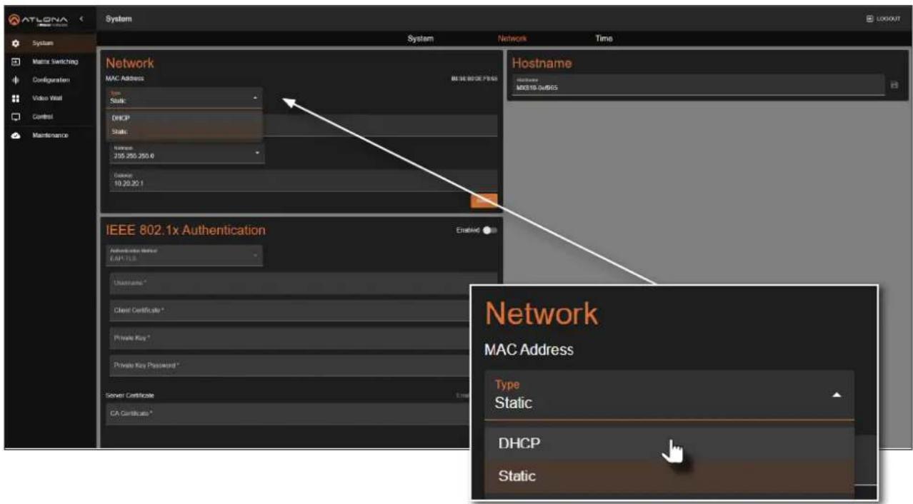
Network Configuration
Setting the IP Mode
The AT-PRO5-MX810 is set to DHCP by default and will receive an IP address from the network's DHCP pool if a DHCP server is available. If no DHCP server is detected, the AT-PRO5-MX810 will automatically assign itself an APIPA address in the range 169.254.0.1 to 169.254.255.254, with a subnet mask of 255.255.0.0. A static IP address can also be specified.

IMPORTANT: Before assigning a static IP address to the AT-PRO5-MX810, it is recommended to consult with the network or system administrator and obtain a available IP address. Assigning the AT-PRO5-MX810 to an IP address that is already in use can result in network issues or difficulty in accessing the AT-PRO5-MX810.
Static IP Mode
- Log in to the web server.
- Click System in the side menu bar.
- Click Network in the top menu bar.
-
Locate the Network window group.
-
Click the Type drop-down list and select Static.

text_image
ATLONA System System Network Network MAC Address DHCP Static Internet 255-268-280.9 Internet 10.30.30.1 Network MAC Address Type DHCP DHCP Static Network MAC Address Type DHCP DHCP Static- Enter IP address, network mask, and gateway (router) address in the Address, Netmask, and Gateway fields, respectively.
- Click the SAVE button to commit changes.
Device Operation
DHCP Mode
The AT-PRO5-MX810 is set to DHCP by default and will receive an IP address from the network's DHCP pool if a DHCP server is available. If no DHCP server is detected, the AT-PRO5-MX810 will automatically assign itself an APIPA address in the range 169.254.0.1 to 169.254.255.254, with a subnet mask of 255.255.0.0.
- Log in to the web server.
- Click System in the side menu bar.
- Click Network in the top menu bar.
-
Locate the Network window group.
-
Click the Type drop-down list and select DHCP.
text_image
ATLONA System System Network Network MAC Address BE3E 802.1x PFS5 Status: DHCP Static: Name: 255 250 255.6 General: 10 20 20.1 Hostname M0010-04/8/5 IEEE 802.1x Authentication Authentication Status EAP-TLS Username* Client Certificate * Private Key * Private Key Password * Server Certificate CA Certificate * Network MAC Address Type Static DHCP Static- Click the SAVE button to commit changes.
Device Operation
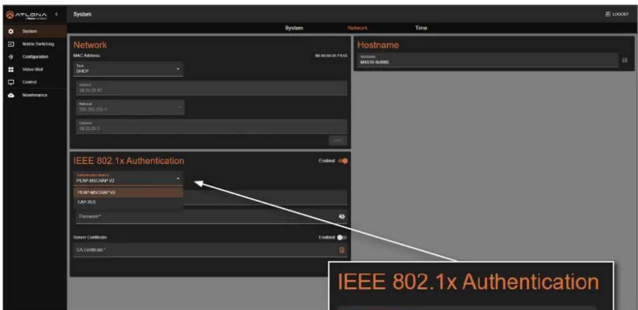
IEEE 802.1x Authentication
802.1x is a server-based port authentication which restricts unauthorized (rogue) clients from connecting to a Local Area Network. In its simplest form, 802.1X usually involves three parties: supplicant (client device), authenticator (Ethernet switch or WAP), and an authentication server. Before the device is permitted on the network, port communication is restricted to Extensible Authentication Protocol over LAN (EAPOL) traffic. If the device passes the authentication process, the authentication server notifies the switch, allowing the client to access the LAN. The illustration below shows the basic architecture.

IMPORTANT: If an 802.1x-enabled AT-PRO5-MX810 is connected to a network without an active or operational authentication server, then the matrix will not function correctly until the expected message is returned from a RADIUS server. If it is unclear as to whether the network uses 802.1x authentication, consult the IT administrator for assistance.

flowchart
graph TD
    A["Supplicant (AT-PRO5-MX810)"] -->|Ethernet (EAPOL)| B["Authenticator (Switch)"]
    B -->|Ethernet (RADIUS)| C["Authentication Server"]
    B -->|Ethernet (Normal traffic)| D["LAN"]
    style A fill:#000,stroke:#fff,color:#fff
    style B fill:#999,stroke:#000,color:#fff
    style C fill:#ccc,stroke:#000
    style D fill:#ccc,stroke:#000
The following options are available:
| Protocol Description | |
| PEAP/MSCHAPv2 | Protected EAP; uses basic credentials in addition to a CA (certificate authority) certificate. |
| EAP-TLS | EAP Transport Layer Security; uses a client certificate, private key, private key password, and CA (certificate authority) certificate. |
Device Operation
- Log in to the web server.
- Click System in the side menu bar.
-
Click Network in the top menu bar.
-
Locate the IEEE 802.1x Authentication window group.
-
Click the Enabled toggle button.
-
Click the Authentication Method drop-down list and select the desired authentication method. In the example below, PEAP/MSCHAPv2 is selected. Once a method is selected, the required fields for that method will be displayed. Enter the required information in each field.
text_image
ATLONA System Network MAC Address Type: DHCP Address: 10.30.20.87 Network: 250.250.250.1 Services: 10.30.20.1 Network Hostname Access: M0319-0x065 IEEE 802.1x Authentication Server Certificate EA/CE/Certificate * IEEE 802.1x Authentication- Click the SAVE button to commit changes.
Depending upon the authentication method, each field is described as follows:
- Username
The identifier for the user or device that is attempting to connect to the network.
- Password
Enter the password in this field.

text_image
IEEE 802.1x Authentication Authentication Method PEAP-MSCHAP V2 PEAP-MSCHAP V2 EAP-TLS Password * Server Certificate CA Certificate *- CA certificate
A digital certificate issued by a Certificate Authority (CA) that serves as the foundation of trust for verifying other certificates, such as client certificates and server certificates. To upload the certificate, click the Enabled button, above the Server Certificate field, then click the 📋 icon to select the certificate.
- Client Certificate
A digital certificate used to authenticate a device or user attempting to connect to the network. This is typically used in enterprise environments or when added security is desired. To upload the certificate, click the Enabled button, above the Server Certificate field, then click the 🔊 icon to select the certificate.
Device Operation
- Private Key
A component of the public key infrastructure (PKI) and associated with the digital certificate. This key is securely stored and used to prove identity and enable secure communication. Click the 📋 icon to select the private key.
- Private Key Password
This password is designed as a level of security used to protect the private key, associated with a digital certificate. The password is masked by default. Click the 🔒 icon to toggle masking.
The table below provides a field summary. An orange dot indicates that this field will be displayed as part of the authentication method.
| Authentication Method | Username | Password | CA Certificate | Client Certificate | Private Key | Private Key Password |
| PEAP/MSCHAPv2 | ||||||
| EAP-TLS |
Device Operation
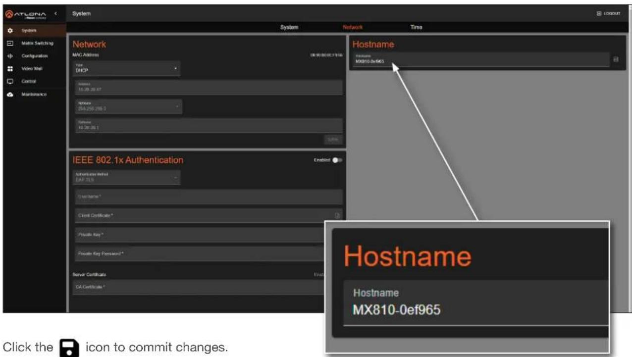
Setting the Host Name
By default, the AT-PRO5-MX810 is assigned a hostname, which is constructed as follows:
MX810-[last six digits of MAC address]
For example, a default hostname might look like this: MX810-0ef965. This value can be changed to easily identify the AT-PRO5-MX810 within Velocity Device Manager or on a network. The hostname cannot exceed 15 characters in length.
- Log in to the web server.
- Click System in the side menu bar.
- Click Network in the top menu bar.
- Locate the Hostname window group.
- Click the Hostname field and enter the desired name.
text_image
ATLONA System System Network MAC Address File DHCP Internet 16.29.26.67 Network 255.255.255.0 Software 10.29.26.1 Network IEEE 802.1x Authentication Authentication Required CAP TLS Username* Client Certificate* Private Key* Private Key Password* Server Certificate CA Certificate * Login Network Hostname Hostname MX810-0ef965 Hostname Hostname MX810-0ef965 Click the icon to commit changes.- Click the 📋 icon to commit changes.
System Time
The AT-PRO5-MX810 uses an internal clock to store the current date and time. When setting the time and date, Universal Coordinated Time (UTC) must be used.
Setting the Time Zone
- Log in to the web server.
- Click System in the side menu bar.
- Click Time in the top menu bar.
-
Locate the Time Zone window group.
-
Click the 🙏️ icon to display the list of time zones. Set the desired time zone by clicking it. Alternatively, the Filter field, within the drop-down list, can be used to filter various time zones from the list.
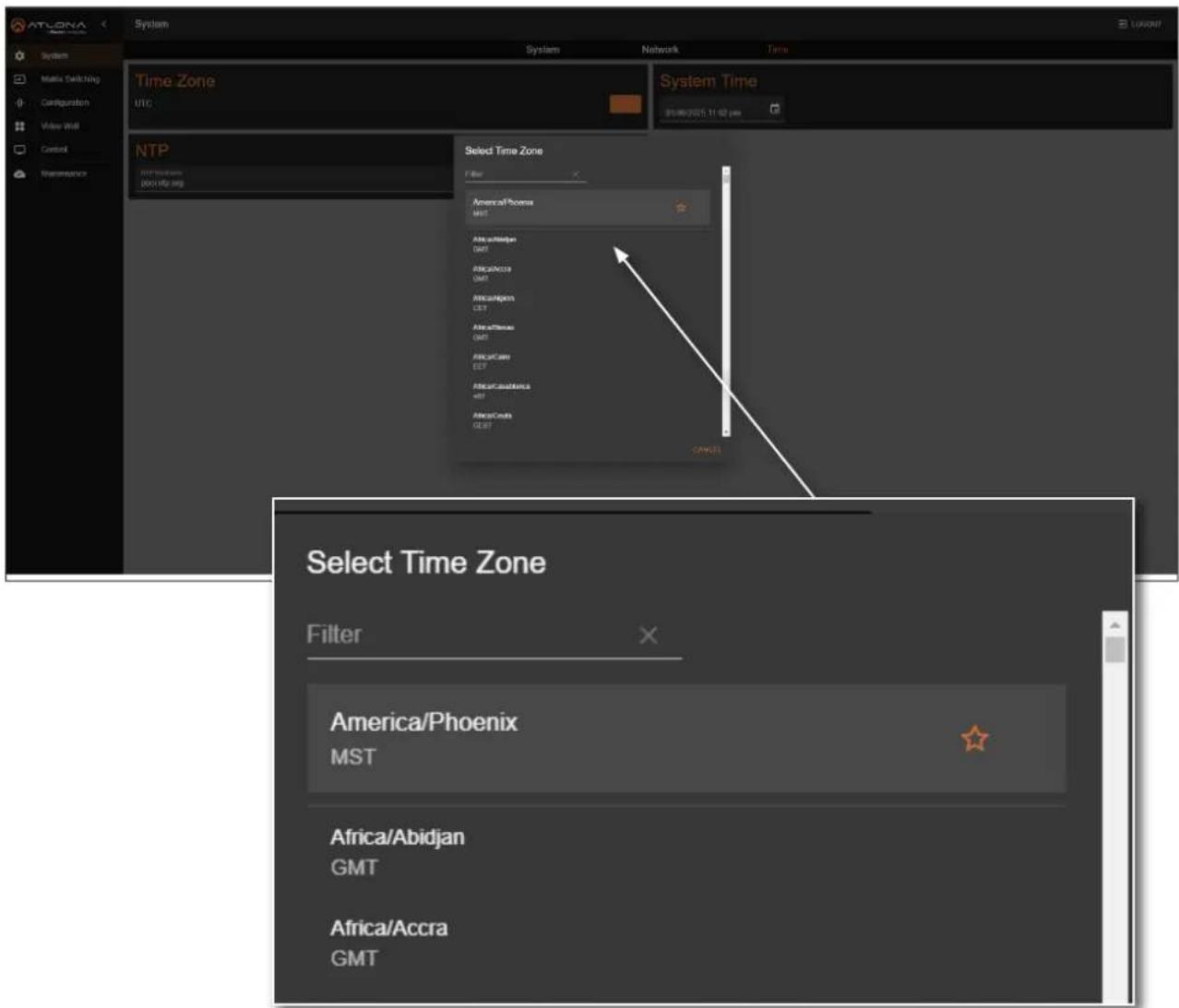
text_image
ATLONA System Network Time Zone UTC System Time 01:00:2025 11:02 pm NTP Interactions 000 HD/MS Select Time Zone Filter America/Phoenix MST Africa/AlOmega GMT Africa/Africa GMT Africa/Hawaii CEF Africa/S�anx GMT Africa/Cano CEF Africa/Canada 48T Africa/Coldx CEF CANCE Select Time Zone Filter America/Phoenix MST Africa/Abidjan GMT Africa/Accra GMTDevice Operation
Assigning an NTP Server
If NTP is functioning correctly, then the date and time will be set automatically. However, the local time will need to be set.
- Log in to the web server.
- Click System in the side menu bar.
- Click Time in the top menu bar.
-
Locate the NTP window group.
-
Click the Enabled toggle switch to enable NTP. When enabled, the toggle switch will be orange.
-
Enter the NTP server name.
-
Click the icon to commit changes.

text_image
ATLONA System System Network Time Time Zone AmericanPhoenix System Time 01/05/2025 04:26 pm NTP Enlisted NTP NTP Hostname pool.ntp.orgDevice Operation
Setting the System Time
- Log in to the web server.
- Click System in the side menu bar.
- Click Time in the top menu bar.
- Locate the System Time window group.
- Click the □icon open up the time settings.

text_image
ATLONA System System Network Time Time Zone AmericaLos, Angelen NTP Enacted System Time 01/12/2025 03:30 pm January 2025 MTV Networks post.ntp.org- Click the correct date from the calendar widget. The currently set date will be highlighted in orange.
- Click on AM or PM and then select the correct hour from the clock widget, then click the correct minute from the next widget that is displayed.
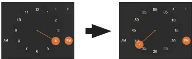
text_image
12 1 11 10 9 8 7 6 5 4 3 2 1 > → 40 35 30 25 20 PM 55 00 05 50 10 45 15 AM PMAlternatively, the time and date can also be entered using the keyboard, within the System Time field.
Matrix Switching
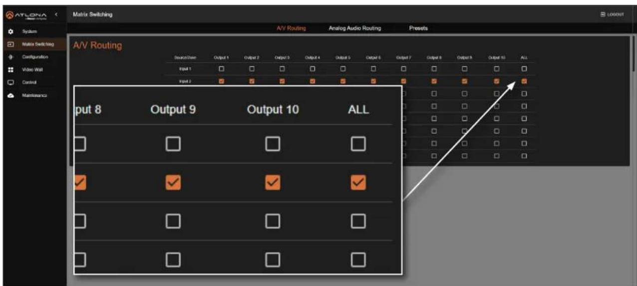
The A/V Routing page manages the assignment of input video sources to outputs. By default, the AT-PRO5-MX810 is configured for 1-to-1 routing, where Input 1 is assigned to Output 1, Input 2 to Output 2, and so forth. Additionally, Input 1 is routed to Output 9, and Input 2 is routed to Output 10.
Video Routing
- Log in to the web server.
- Click Matrix Switching in the side menu bar.
-
Click A/V Routing in the top menu bar.
-
Click the checkboxes in the table to assign an input to an output. The checkbox will be orange once the selection is complete.

text_image
ATLONA Matrix Switching A/V Routing Analog Audio Routing Presets A/V Routing Source/Case Output 1 Output 2 Output 3 Output 4 Output 5 Output 6 Output 7 Output 8 Output 9 Output 10 ALL Input 1 Input 2 Input 3 Input 4 Input 5 Input 6 Input 7 Input 8- To route a single input to all outputs, click the ALL check box. In this example, Input 2 is routed to all outputs (Output 1 - Output 10).
text_image
ATLONA Matrix Switching System Matrix Switching Configuration Video Wall Control Maintenance A/V Routing A/V Routing Analog Audio Routing Presets Source/View Output 1 Output 2 Output 3 Output 4 Output 5 Output 6 Output 7 Output 8 Output 9 Output 10 ALL Input 1 Input 2 Input 3 Input 4 Input 5 Input 6 Input 7 Input 8 Input 9 Input 10 ALL Input 8 Output 9 Output 10 ALLDevice Operation
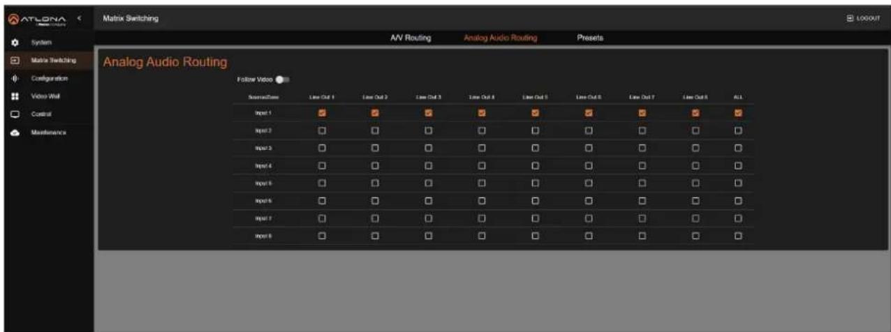
Manual Audio Routing
The Analog Audio Routing page controls the distribution of de-embedded input audio to analog audio outputs. By default, the AT-PRO5-MX810 routes the audio from Input 1 to all audio outputs (Output 1 - Output 10) configured.
- Log in to the web server.
- Click Matrix Switching in the side menu bar.
-
Click Analog Audio Routing in the top menu bar.
-
Make sure that the Follow Video toggle switch is disabled. When disabled, the toggle switch will be gray.
-
Click the checkboxes in the table to assign an input to an output. The checkbox will be orange once the selection is complete.
-
To route a single input to all outputs, click the ALL check box.
text_image
ATLONA Network Switching System Matrix Switching Configuration Video Wall Control Maintenance Matrix Switching A/V Routing Analog Audio Routing Presets Analog Audio Routing Follow Video SourceTime Line Out 1 Line Out 2 Line Out 3 Line Out 4 Line Out 5 Line Out 6 Line Out 7 Line Out 8 ALL Input 1 Input 2 Input 3 Input 4 Input 5 Input 6 Input 7 Input 8Follow Video
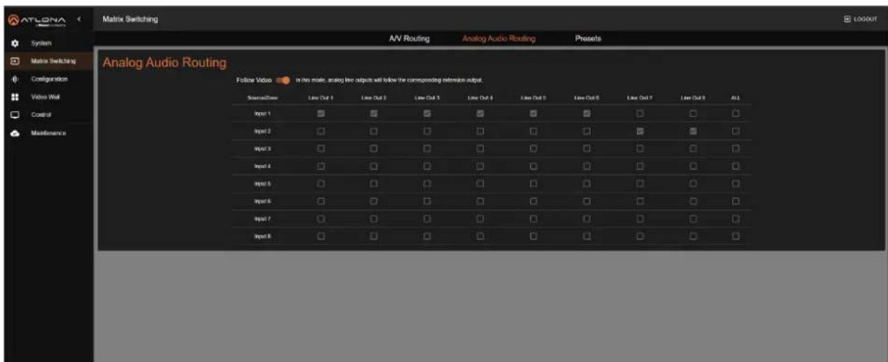
This feature is enabled by default. When Follow Video toggle switch is enabled, the toggle switch will be orange and manual audio routing is disabled. In this mode, each audio output automatically de-embeds audio from its corresponding video output. For instance, Audio Output 1 will de-embed audio from EXT1.
text_image
ATLONA System Matrix Switching Configuration Video Wall Control Maintenance Matrix Switching A/V Routing Analog Audio Routing Presets Analog Audio Routing Follow Video In this mode, analog live outputs will follow the corresponding reliable output. StreamTime Line Out 1 Line Out 2 Line Out 3 Line Out 4 Line Out 5 Line Out 6 Line Out 7 Line Out 8 ALL Input 1 Input 2 Input 3 Input 4 Input 5 Input 6 Input 7 Input 8Device Operation
Saving / Loading Switching Presets
The Presets page allows saving and loading of input/output switch configurations to and from the matrix. Up to ten switching presets can be stored.
- Log in to the web server.
-
Click Matrix Switching in the side menu bar.
-
Click Presets in the top menu bar.
-
Enter the name of the preset in the desired Preset field, then click the icon to save the name of the preset.
-
Click the Save button to assign the currently configured configuration to the preset. To remove the configuration from the preset, click the Clear button.

text_image
ATLONA Matrix Switching System Matrix Switching Configuration Video Wall Control Maintenance A/V Routing Analog Audio Routing Prepots Project 1 Project Name Isching Project 2 Project Name Preset 3 Project Name Preset 4 Project Name Preset 5 Project 6 Project 7 Project Name Preset 8 Project 9 Project 10 Preset 11 Preset 12 Preset 13 Preset 14 Preset 15 Preset 16 Preset 17 Preset 18 Preset 19 Preset 20 Preset 21 Preset 22 Preset 23 Preset 24 Preset 25 Preset 26 Preset 27 Preset 28 Preset 29 Preset 30 Preset 31 Preset 32 Preset 33 Preset 34 Preset 35 Preset 36 Preset 37 Preset 38 Preset 39 Preset 40 Preset 41 Preset 42 Preset 43 Preset 44 Preset 45 Preset 46 Preset 47 Preset 48 Preset 49 Preset 50 Preset 51 Preset 52 Preset 53 Preset 54 Preset 55 Preset 56 Preset 57 Preset 58 Preset 59 Preset 60 Preset 61 Preset 62 Preset 63 Preset 64 Preset 65 Preset 66 Preset 67 Preset 68 Preset 69 Preset 70 Preset 71 Preset 72 Preset 73 Preset 74 Preset 75 Preset 76 Preset 77 Preset 78 Preset 79 Preset 80Activating a Preset
- Log in to the web server.
- Click Matrix Switching in the side menu bar.
-
Click Presets in the top menu bar.
-
Select the desired preset and click ACTIVATE to load the saved routing state.

text_image
ATLONA Matrix Switching System Matrix Switching Configuration Video Wall Control Maintenance A/V Routing Analog Audio Routing Presels Preset 1 Preset Name Preset 2 Preset 3 Preset 4 Preset 5 Preset 6 Preset 7 Preset 8 Preset 9 Preset 10 Preset 11 Preset 12 Preset 13 Preset 14 Preset 15 Preset 16 Preset 17 Preset 18 Preset 19 Preset 20 Preset 21 Preset 22 Preset 23 Preset 24 Preset 25 Preset 26 Preset 27 Preset 28 Preset 29 Preset 30 Preset 31 Preset 32 Preset 33 Preset 34 Preset 35 Preset 36 Preset 37 Preset 38 Preset 39 Preset 40 Preset 41 Preset 42 Preset 43 Preset 44 Preset 45 Preset 46 Preset 47 Preset 48 Preset 49 Preset 50 Preset 51 Preset 52 Preset 53 Preset 54 Preset 55 Preset 56 Preset 57 Preset 58 Preset 59 Preset 60 Preset Name Preset 1 ACTIVATE CLEAR SAVEMatrix Configuration
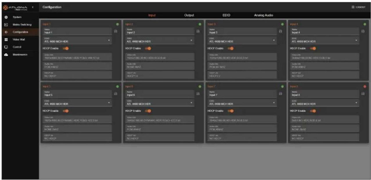
This section covers modification of input/output names, EDID management, and HDCP capabilities for each input, while also displaying video and audio information for each input.
Changing the Input Name
By default, inputs are named Input 1, Input 2, Input 3, and so on. It is recommended to rename each input based on the connected source.
- Log in to the web server.
- Click Configuration in the side menu bar.
- Click Input in the top menu bar.
text_image
ATLONA Configuration Input 1 Input 2 Input 3 Input 4 Output 1 Output 2 Output 3 Output 4 ATL 4K50 MCH HDR ATL 4K50 MCH HDR ATL 4K50 MCH HDR ATL 4K50 MCH HDR ATL 4K50 MCH HDR ATL 4K50 MCH HDR ATL 4K50 MCH HDR ATL 4K50 MCH HDR ATL 4K50 MCH HDR ATL 4K50 MCH HDR HDCP Enable HDCP Enable HDCP Enable Output 1 Output 2 Output 3 Output 4 Output 5 Output 6 Output 7 Output 8 Output 9 Output 10 Output 11 Output 12 Output 13 Output 14 Output 15 Output 16 Output 17 Output 18 Output 19 Output 20 Output 21 Output 22 Output 23 Output 24 Output 25 Output 26 Output 27 Output 28 Output 29 Output 30 Output 31 Output 32 Output 33 Output 34 Output 35 Output 36 Output 37 Output 38 Output 39 Output 40 Output 41 Output 42 Output 43 Output 44 Output 45 Output 46 Output 47 Output 48 Output 49 Output 50 Output 51 Output 52 Output 53 Output 54 Output 55 Output 56 Output 57 Output 58 Output 59 Output 60 Output 61 Output 62 Output 63 Output 64 Output 65 Output 66 Output 67 Output 68 Output 69 Output 70 Output 71 Output 72 Output 73 Output 74 Output 75 Output 76 Output 77 Output 78 Output 79 Output 80 HDCP Enable HDCP Enable HDCP Enable HDCP Enable HDCP Enable HDCP Enable HDCP Enable HDCP Enable HDCP Enable HDCP Enable HDCP Enable HDCP Enable HDCP Enable HDCP Enable HDCP Enable HDCP Enable HDCP Enable HDCP Enable HDCP Enable HDCP Enable HDCP Beaus HDCP Beaus HDCP Beaus HDCP Beaus HDCP Beaus HDCP Beaus HDCP Beaus HDCP Beaus HDCP Beaus HDCP Beaus HDCP Beaus HDCP Beaus HDCP Beaus HDCP Beaus HDCP Beaus HDCP Beaus HDCP Beaus HDC Paus HDC Paus HDC Paus HDC Paus HDC Paus HDC Paus HDC Paus HDC Paus HDC Paus HDC Paus HDC Paus HDC Paus HDC Paus HDC Paus HDC Paus HDC Paus HDC Paus HDC Paus HDC Paus HDC Paus HDC DUTS HDC DUTS HDC DUTS HDC DUTS HDC DUTS HDC DUTS HDC DUTS HDC DUTS HDC DUTS HDC DUTS HDC DUTS HDC DUTS HDC DUTS HDC DUTS HDC DUTS HDC DUTS HDC DUTS HDC TURS HDC TURS HDC TURS HDC TURS HDC TURS HDC TURS HDC TURS HDC TURS HDC TURS HDC TURS HDC TURS HDC TURS HDC TURS HDC TURS HDC TURS HDC TURS HDC TURS HDOUPLRPLRPLRPLRPLRPLRPLRPLRPLRPLRPLRPLRPLRPLRPLRPLRPLRPLRPLRPLRPLRPLRPLRPLRPLRPLRPLRPLRPLRPLRPLRPLRPLRPLRPLRPLRPLRPLRPLRPLRPLRPLRPLRPLRPLRPLRPLRPLRPLRPLRPL RRLRRLRRLRRLRRLRRLRRLRRLRRLRRLRRLRRLRRLRRLRRLRRLRRLRRLRRLRRLRRLRRLRRLRRLRRLRRLRRLRRLRRLRRLRRLRRLRRLRRLRRLRRLRRLRRLRRLRRLRRLRRLRRLRRLRRLRRLRRLRRLRRLRRLRRL RRL RRL RRL RRL RRL RRL RRL RRL RRL RRL RRL RRL RRL RRL RRL RRL RRL RRL RRL RRL RRL RRL RRL RRL RRL RRL RRL RRL RRL RRL RRL RRL RRL RRL RRL RRL RRL RRL RRL RRL RRL RRL RRL RRL RRL RRL RRL RRL RRL RRL SMLTMLTMLTMLTMLTMLTMLTMLTMLTMLTMLTMLTMLTMLTMLTMLTMLTMLTMLTMLTMLTMLTMLTMLTMLTMLTMLTMLTMLTMLTMLTMLTMLTMLTMLTMLTMLTMLTMLTMLTMLTMLTMLTMLTMLTMLTMLTMLTMLTMLTML TMLTMLTMLTMLTMLTMLTMLTMLTMLTMLTMLTMLTMLTMLTMLTMLTMLTMLTMLTMLTMLTMLTMLTMLTMLTMLTMLTMLTMLTMLTMLTMLTMLTMLTMLTMLTMLTMLTMLTMLTMLTMLTMLTMLTMLTMLTMLTMLTMLTML:SLM:SLM:SLM:SLM:SLM:SLM:SLM:SLM:SLM:SLM:SLM:SLM:SLM:SLM:SLM:SLM:SLM:SLM:SLM:SLM:SLM:SLM:SLM:SLM:SLM:SLM:SLM:SLM:SLM:SLM:SLM:SLM:SLM:SLM:TUL:TL:TL:TL:TL:TL:TL:TL:TL:TL:TL:TL:TL:TL:TL:TL:TL:TL:TL:TL:TL:TL:TL:TL:TL:TL:TL:TL:TL:TL:TL:TL:TL:TL:TL:TL:TL:TL:TL:TL:TL:TL:TL:TL:TL:TL:TL:TL:TL:TL:TL:TTLL :TTLL :TTLL :TTLL :TTLL :TTLL :TTLL :TTLL :TTLL :TTLL :TTLL :TTLL :TTLL :TTLL :TTLL :TTLL :TTLL :TTLL :TTLL :TTLL :TTLL :TTLL :TTLL :TTLL :TTLL :TTLL :TTLL :TTLL :TTLL :TTLL :TTLL :TTLL :TTLL :TTLL : TTLL :TTLL :TTLL :TTLL :TTLL :TTLL :TTLL :TTLL :TTLL :TTLL :TTLL :TTLL :TTLL :TTLL :TTLL :TTLL :TTLL :TTLL :TTLL :TTLL :TTLL :TTLL :TTLL :TTLL :TTLL :TTLL :TTLL :TTLL :TTLL :TTLL :TTLL :TTLL :TTLL :TTILL :TTILL :TTILL :TTILL :TTILL :TTILL :TTILL :TTILL :TTILL :TTILL :TTILL :TTILL :TTILL :TTILL :TTILL :TTILL :TTILL :TTILL :TTILL :TTILL :TTILL :TTILL :TTILL :TTILL :TTILL :TTILL :TTILL :TTILL :TTILL :TTILL :TTILL :TTILL :TTILL :TTILL |- Click the Name field of the desired input.
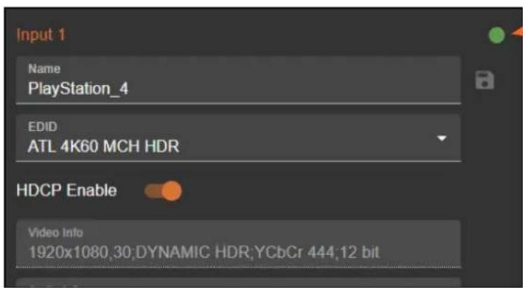
- Enter the desired name for the input. In this example, PlayStation_4 is used, identifying the source.
- Click the icon to save the name of the input. Note that the name of the input, in orange, will not change. The new input name will appear under the Matrix Switching > A/V Routing and Matrix Switching > Analog Audio Routing pages.
text_image
Input 1 Name PlayStation_4 EDID ATL 4K60 MCH HDR HDCP Enable Video Info 1920x1080,30:DYNAMIC HDR;YCbCr 444,12 bitConnection status
The dot in the top-right corner of each input box shows the connection status:
- Green: The input source is connected to the corresponding port and has an active signal.
- Orange: The input source is not connected to the corresponding port.
Device Operation
Selecting an EDID
Before sending picture and sound to a display, a source device reads the EDID (Extended Display Identification Data) from the display. This data specifies the video and audio formats the display supports. The AT-PRO5-MX810 includes several pre-programmed EDID options and also allows the storage of custom EDID data.. Refer to EDID Management (page 40) for more information.
- Log in to the web server.
- Click Configuration in the side menu bar.
- Click Input in the top menu bar.

text_image
ATLONA Configuration System Matrix Switching Configuration Value Wall Control Maintenance Input 1 Input 2 Input 3 Input 4 Copy from Output 1 Copy from Output 2 Copy from Output 3 Copy from Output 4 Copy from Output 5 Copy from Output 6 Copy from Output 7 Copy from Output 8 Copy from Output 9 Copy from Output 10 ATL 4K60 MCH HDR ATL 4K60 MCH ATL 4K60 PCM MCH HDR ATL 4K60 PCM MCH ATL 4K60 2CH ATL 108SP MCH ATL 108SP 2CH ATL 108SP DO ATL 108SP DVE ATL 720P DO ATL 720P 2CH Custom 1 Custom 2 Custom 3 Custom 4 Custom 5 Input 1 Input 2 Input 3 Input 4 Copy from Output 1 Copy from Output 2 Copy from Output 3 Copy from Output 4 Copy from Output 5 Copy from Output 6 Copy from Output 7 Copy from Output 8 Copy from Output 9 Copy from Output 10 ATL 4K60 MCH HDR ATL 4K60 MCH ATHI 4K60 PCM MCH HDR ATL 4K60 PCM MCH ATL 4K60 2CH ATL 108SP MCH ATL 108SP 2CH ATL 108SP DO ATL 108SP DVE ATL 720P DO ATL 720P 2CH Custom 1 Custom 2-
Click the EDID drop-down list and select the desired EDID. In this example, the ATL 4K60 MCH HDR EDID is being selected.
-
Click on the highlighted EDID to commit changes.
Device Operation
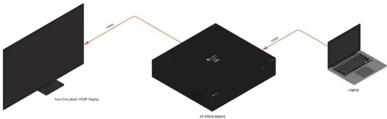
HDCP Content
Transmitting HDCP content to a display that is not HDCP compliant can result in "snow", image flickering, or no picture. In the illustration below, a laptop source is connected to the AT-PRO5-MX810, which is connected to a display that is not HDCP compliant.

IMPORTANT: Not all source devices are capable of transmitting non-HDCP content.
For example, Sony PlayStation ^® gaming consoles and Mac ^® computers always transmit HDCP-encrypted content.
flowchart
graph LR
    A["Non-Compliant HDCP Display"] -->|H26s| B["AT-PRC5-MX810"]
    B -->|H26s| C["Laptop"]
By default, the laptop may transmit HDCP content. However, when connected to a display that does not support HDCP, the laptop must be instructed to send non-HDCP content in order for the content to be displayed.
- Log in to the web server.
- Click Configuration in the side menu bar.
-
Click Input in the top menu bar.
-
Click the toggle switch for the desired input. For example, toggling HDCP Enable under Input 1 to the Off position will prompt the source device to send non-HDCP content, if it is supported.

text_image
Input 1 Name Input 1 EDID ATL 4K60 MCH HDR HDCP Enable Video Info 1920x1080,30,DYNAMIC HDR,YCbCr 444;12 bitChanging the Output Name
By default, inputs are named Output 1, Output 2, Output 3, and so on. It is recommended to rename each output based on the connected output device.
- Log in to the web server.
- Click Configuration in the side menu bar.
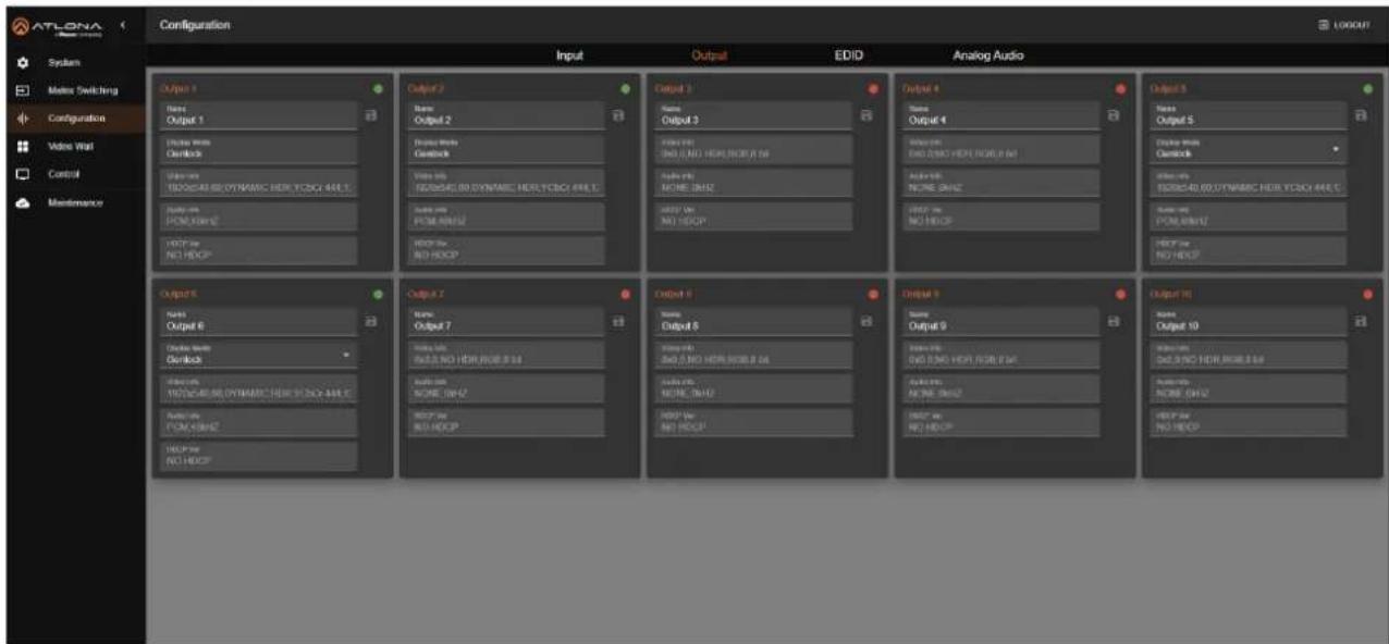
- Click Output in the top menu bar.
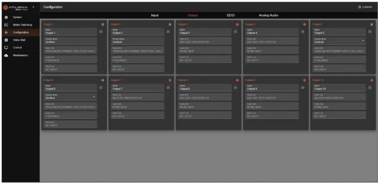
text_image
ATLONA System Matrix Switching Configuration Video Wall Control Maintenance Configuration Input Output EDID Analog Audio Output 1 Name Output 1 Double Mode Genlock Video mix ISO/0x540.60 DYNAMIC HDR YC3G: 444.1 Audio mix PCM,48HZ HDCP var NO HDCP Output 2 Name Output 2 Display Mode Genlock Video mix ISO/0x540.60 DYNAMIC HDR YC3G: 444.1 Audio mix PCM,48HZ HDCP var NO HDCP Output 3 Name Output 3 Video mix: ISO 0. NO HDR/RGB 8 dB Audio mix: NONE 0. kHzZ HDCP var NO HDCP Output 4 Name Output 4 Video mix: ISO 0. NO HDR/RGB 8 dB Audio mix: NONE 0. kHzZ HDCP var NO HDCP Output 5 Name Output 5 Display Mode Genlock Video mix: ISO/0x540.60 DYNAMIC HDR YC3G: 444.1 Audio mix: PCM,48HZ HDCP var NO HDCP Output 6 Name Output 6 Double Mode Genlock Video mix: ISO/0x540.60 DYNAMIC HDR YC3G: 444.1 Audio mix: PCM,48HZ HDCP var NO HDCP Output 7 Name Output 7 Video mix: ISO 0. NO HDR/RGB 8 dB Audio mix: NONE 0. kHzZ HDCP var NO HDCP Output 8 Name Output 8 Video mix: ISO 0. NO HDR/RGB 8 dB Audio mix: NONE 0. kHzZ HDCP var NO HDCP Output 9 Name Output 9 Video mix: ISO 0. NO HDR/RGB 8 dB Audio mix: NONE 0. kHzZ HDCP var NO HDCP Output 10 Name Output 10 Video mix: ISO 0. NO HDR/RGB 8 dB Audio mix: NONE 0. kHzZ HDCP var NO HDCP- Click the Name field of the desired output.
- Enter the desired name for the output. In this example, Samsung1 is used, identifying the sink device.
- Click the icon to save the name of the output. Note that the name of the output, in orange, will not change. The new output name will appear under the Matrix Switching > A/V Routing and Matrix Switching > Analog Audio Routing pages.
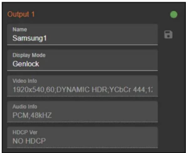
text_image
Output 1 Name Samsung1 Display Mode Genlock Video Info 1920x540,60;DYNAMIC HDR;YCbCr 444;1; Audio Info PCM:48kHz HDCP Ver NO HDCPDevice Operation
Changing the Display Mode
When the corresponding SDVoE output is connected with an AT-PRO5-101-SC-RX receiver, the display mode can be switched between Genlock or Scaler.

IMPORTANT: Display modes can only be selected when an AT-PRO5-101-SC-TX receiver is connected to an SDVoE output. If an AT-PRO5-101-RX receiver is used, the drop-down list will not appear.
- Log in to the web server.
- Click Configuration in the side menu bar.
- Click Output in the top menu bar.
text_image
ATLONA System Masters Switching Configuration Video Wall Control Maintenance Configuration Input Output EDID Analog Audio Output 1 Name Output 1 Delete Home Quickbox Volume: 300V/80 DYNAMIC HDB YCSCY 44E.1 Output: 500V/80 DYNAMIC HDB YCSCY 44E.1 Output: 500V/80 DYNAMIC HDB YCSCY 44E.1 Output: 500V/80 DYNAMIC HDB YCSCY 44E.1 Output: 500V/80 DYNAMIC HDB YCSCY 44E.1 Output: 100V/80 DYNAMIC HDB YCSCY 44E.1 Output: 100V/80 DYNAMIC HDB YCSCY 44E.1 Output: 100V/80 DYNAMIC HDB YCSCY 44E.1 Output: 100V/80 DYNAMIC HDB YCSCY 44E.1 Output: 200V/80 DYNAMIC HDB YCSCY 44E.1 Output: 200V/80 DYNAMIC HDB YCSCY 44E.1 Output: 200V/80 DYNAMIC HDB YCSCY 44E.1 Output: 200V/80 DYNAMIC HDB YCSCY 44E.1 Output: 500V/80 DYNAMIC HDB YCSCY 44E.1 Output: 500V/80 DYNAMIC HDB YCSCY 44E.1 Output: 500V/80 DYNAMIC HDB YCSCY 44E.1 Output: 700V/80 DYNAMIC HDB YCSCY 44E.1 Output: 700V/80 DYNAMIC HDB YCSCY 44E.1 Output: 700V/80 DYNAMIC HDB YCSCY 44E.1 Output: 700V/80 DYNAMIC HDB YCSCY 44E.1 Output: 900V/80 DYNAMIC HDB YCSCY 44E.1 Output: 900V/80 DYNAMIC HDB YCSCY 44E.1 Output: 900V/80 DYNAMIC HDB YCSCY 44E.1 Output: 900V/80 DYNAMIC HDB YCSCY 44E.1 Output: 100V/80 DYNAMIC HDB YCSCY 44E.1 Output: 100V/80 DYNAMIC HDB YCSCY 44E.1- Click the Display Mode drop-down list and select the desired display mode.

text_image
Output 6 Name Output 6 Display Mode Genlock Genlock Scaler PCM,48kHz HDCP Ver HDCP1.4Refer to Table 1.1 on the next page for a description of display modes.
Table 1.1 - Display Modes
| Mode Description | ||
| Genlock | This mode mimics the behavior of a direct wired connection. The HDMI signal is mostly unchanged, with only light video compression applied to fit within the cable's 10Gbps network bandwidth. The display connected to the receiver is synchronized (genlocked) to the source connected to the matrix. When multiple receivers use the same input, all connected displays sync to that source, ensuring complete synchronization across all displays. Genlock mode provides the lowest possible latency. | |
| (ZWAT) NOTE: Genlock is required to pass HDR signals. | ||
| Scaler | This mode allows selection between Fast scaler and Genlock scaler modes. | |
| Mode Description | ||
| Fast scaler | This mode allows for quick source switching with resolution scaling or frame rate conversion, as needed. It keeps the output timing and format constant, so the display doesn't need to re-synchronize, resulting in smooth transitions. However, a frame buffer adds a latency of 1 to 2 frames. | |
| Genlock scaler | This mode combines the low latency and source synchronization of Genlock mode with the scaling features of Fast Switch mode. When enabled, the output port can handle format conversions, like 1080p to 720p, but does not perform frame rate conversion, avoiding any frame buffer latency. By keeping the output synchronized (genlocked) to the source, this mode ensures the lowest possible latency for displays with resolutions different from the source. | |
When set to Scaler mode, two additional drop-down lists will be available: Scaler Mode and Output Resolution. Refer to the table above for information on the Fast scaler and Genlock scaler modes.
The Output Resolution drop-down list provides the following resolutions, listed in Table 1.2.
Table 1.2 - Available Output Resolutions in Scaler Mode.
| Resolutions | |||
| 720P 1080P 2160P 4096x2160 | |||
| 1024x768 1280x768 1280x960 1280x1024 | |||
| 1360x768 1400x1050 1600x1200 1680x1050 | |||
| 1920x1200 |
Device Operation
EDID Management
Before a source can send picture and sound to a display device, the source reads the EDID (Extended Display Identification Data) stored in the display. The EDID contains information about what type of video and audio formats are supported by the display. The AT-PRO5-MX810 can use a factory-programmed EDID, the downstream EDID (from the display/sink) or a custom EDID. The AT-PRO5-MX810 provides a five blank memory locations that can be used to store EDID data.
By default, the AT-PRO5-MX810 will use the ATL 4K60 MCH HDR EDID for each input. However, this can be modified.
- Log in to the web server.
- Click Configuration in the side menu bar.
- Click EDID in the top menu bar.

- Click the Select EDID drop-down list to select the desired EDID.
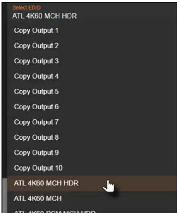
text_image
Select EDID ATL 4K60 MCH HDR Copy Output 1 Copy Output 2 Copy Output 3 Copy Output 4 Copy Output 5 Copy Output 6 Copy Output 7 Copy Output 8 Copy Output 9 Copy Output 10 ATL 4K60 MCH HDR ATL 4K60 MCH ATL 4K60 PCM MCH HDR- The EDID Name field displays the EDID name and the raw EDID data will be displayed in the EDID Data window.
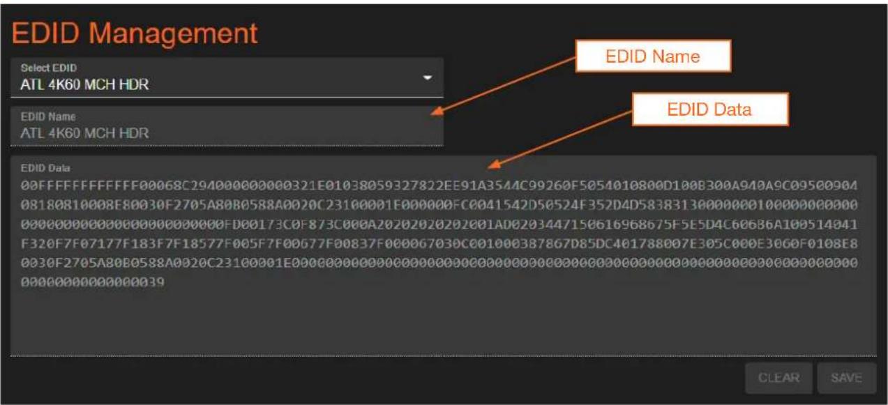
text_image
EDID Management Select EDID ATL 4K60 MCH HDR EDID Name ATL 4K60 MCH HDR EDID Data 00FFFFFFF00068C2940000000321E01038059327822EE91A3544C99260F5054010800D100B300A940A9C09500904 08180810008E80030F2705A80B0588A0020C23100001E000000FC0041542D50524F352D4D58383130000001000000000 0000000000000000000FD00173C0F873C000A2020202020201AD0203447150616968675F5E5D4C606B6A109514041 F320F7F07177F183F7F18577F005F7F0G77F00837F00006703C001000387867D85DC401788007E305C00E30GOF0108E8 033F2705A8OBO588A022C2310001E0000000000000000000000000000 OOOOOOOOOOOOOOOOOOOOOOOOOOOOOOOOOOOOOOOOOOOOOOOOOOOOOOOOOOOOOOOOOOOOOOOOOOOOOOOOOOOOOOOOOOO OOOOOOOOOOOOOOOO39 EDID Name EDID Data CLEAR SAVEEDID Presets
The AT-PRO5-MX810 provides the option of selecting an EDID. The following options are available from the EDID drop-down list, for each input.
| EDID Description | |
| Copy from Output 1... | Uses the EDID that is connected to the selected output. |
| Copy from Output 10 | |
| ATL 4K60 MCH HDR | 3840 x 2160 @ 60 Hz / multichannel audio / HDR |
| ATL 4K60 MCH | 3840 x 2160 @ 60 Hz / multichannel audio |
| ATL 4K60 PCM MCH HDR | 3840 x 2160 @ 60 Hz / multichannel LPCM audio / HDR |
| ATL 4K60 PCM MCH | 3840 x 2160 @ 60 Hz / multichannel LPCM audio |
| ATL 4K60 2CH | 3840 x 2160 @ 60 Hz / 2-channel audio |
| ATL 1080P MCH | 1920 x 1080 / multichannel audio |
| ATL 1080P 2CH | 1920 x 1080 / 2-channel audio |
| ATL 1080P DD | 1920 x 1080 / Dolby® Digital |
| ATL 1080P DVI | 1920 x 1080 / DVI |
| ATL 720P DD | 1280 x 720 / Dolby® Digital |
| ATL 720P 2CH | 1280 x 720 / 2-channel audio |
| Custom 1...Custom 5 | Selects a custom EDID preset |
Device Operation
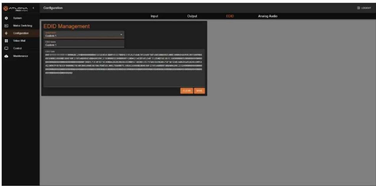
Creating a Custom EDID
The AT-PRO5-MX810 provides a five blank memory locations that can be used to store EDID data. These memory locations are non-volatile and the EDID data is retained after power is disconnected from the unit.
- Log in to the web server.
- Click Configuration in the side menu bar.
-
Click EDID in the top menu bar.
-
Click the Select EDID drop-down list to select one of the custom EDID memory locations. In this example, Custom 1 is selected.
text_image
ATLONA Configuration System Matrix Switching Configuration Video Wall Control Maintenance EDID Management Custom 1 Custom 1 EVID Name Custom 1 EVID Name 0017382222222222222222222222222222222222222222222222222222222222222222222222222222222222222222222222222222 001738222222222222222222222222222222222222222222222 001738198738198615478516888888888888888888888888888888888888888888888888888888888888888888888888888888 0017381987381986154785168888888888888888888888888888- Type the name of the EDID in the EDID Name field.
- Copy and paste the raw EDID data in the EDID Data field. Raw EDID data should not contain any spaces or delimiters.
- Click the SAVE button.
Device Operation
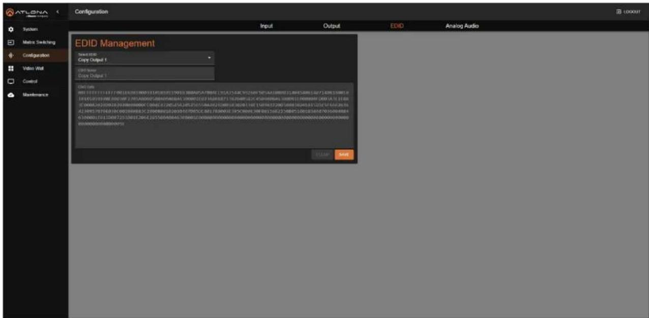
Copying a Downstream EDID
The AT-PRO5-MX810 provides a five blank memory locations that can be used to store EDID data. These memory locations are non-volatile and the EDID data is retained after power is disconnected from the unit.
- Connect an HDMI cable from the HDMI output port (or HDMI output on the receiver) to the HDMI input on the display, containing the EDID to be stored.
- Log in to the web server.
- Click Configuration in the side menu bar.
- Click EDID in the top menu bar.
- Click the Select EDID drop-down list to select one of the Copy Output selections. In this example, Copy Output 1 is selected.
text_image
ATLONA Configuration System Matrix Switching Configuration Video Wall Control Maintenance EDID Management Select EDID Copy Output 1 OUT Power Copy Output 2 END List 400 168 175 183 190 201 210 220 230 240 250 260 270 280 290 300 310 320 330 340 350 360 370 380 390 400 410 420 430 440 450 460 470 480 490 500 510 520 530 540 550 560 570 580 590 600 610 620 630 640 650 660 670 680 690 700 710 720 730 740 750 760 770 780 790 800 810 820 830 840 850 860 870 880 890 900 910 920 930 940 950 960 970 980 990 ELEEP SelectIf the EDID cannot be retrieved, then ERROR, UNCONNECT will be displayed in the EDID Data field. Check the cable connections or try another cable.
- Click the SAVE button.
Video Walls

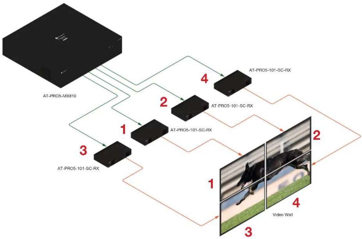
IMPORTANT: In order to use the video wall feature, AT-PRO5-101-SC-RX scaling receivers must be used.
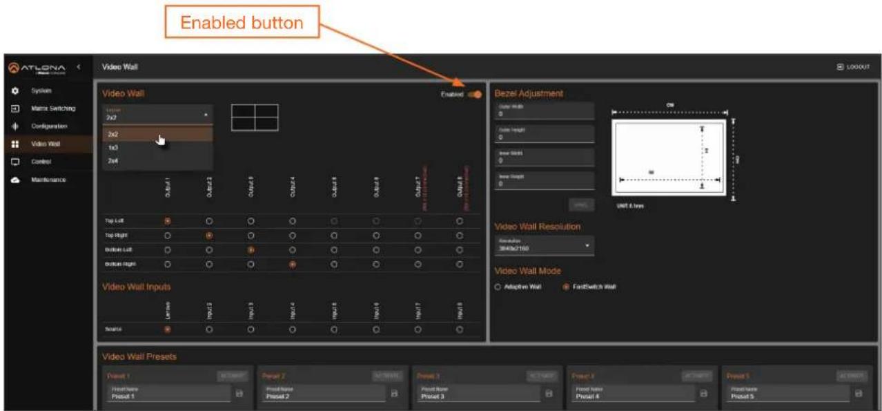
Creating a Video Wall
- Log in to the web server.
- Click Video Wall in the side menu bar.
- Click the Enabled toggle switch to enable the video wall feature. When enabled, the toggle switch will be orange.
- Click the Layout drop-down list to select the desired video wall configuration. In this example, 2x2 has been selected.
text_image
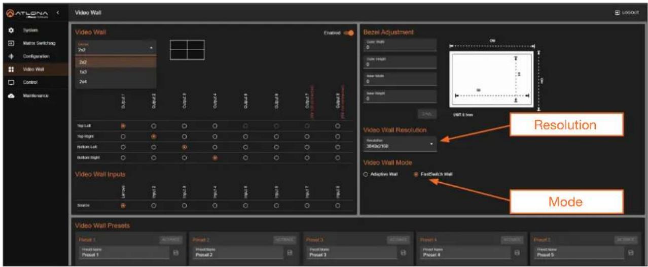
Enabled button Video Wall Video Wall Bezel Adjustment Output Height 0 Video Wall Input 0 Inner Widths 0 Inner Widths 0 Input 6 axes Video Wall Resolution Resolution 3848x2160 Video Wall Mode Adaptive Wall FastSwitch Wall Video Wall Inputs Source Video Wall Presets Preset 1 Preset 2 Preset 3 Preset 4 Preset 5 Front Name Preset 1 Front Name Preset 2 Front Name Preset 3 Preset 4 Preset 5- Under the Video Wall Outputs section, click the radio button that corresponds with the desired output. In this example, Output 1 has been assigned to the Top Left window, Output 2 to the Top Right window, and so on. Refer to the illustration below.

- Under the Video Wall Inputs section, click the radio button for the desired input video source. In this example, Input 1 ("Lenovo") is selected.
- Click the Resolution drop-down list, located under the Video Wall Resolution section, and select the desired resolution. In this example, 3840x2160 is selected.
text_image
ATLONA System Matrix Switching Configuration Video Wall Control Maintenance Video Wall Video Wall Video Wall Enabled Bezel Adjustment User must 0 User height 0 New width 0 New height 0 UMT Error 100% 100% 100% 100% 100% 100% 100% 100% 100% 100% 100% 100% 100% 100% 100% 100% 100% 100% 100% 100% 100% 100% 100% 100% 100% 100% 100% 100% 100% 100% 100% 100% 100% 100% 100% 100% 100% 100% 100% 100% 100% 100% 100% 100% 100% 100% 100% 100% 25% 15% 25% 35% 45% 55% 65% 75% 85% 95% 105% 155% 255% 355% 455% 555% 655% 755% 855% 955% 1055% 1555% 2555% 3555% 4555% 5555% 6555% 7555% 8555% 9555% 1055% 1555% 2555% 3555% 4555% 5555% 6555% 7555% 8555% 9555% 1055% 1555% 2555% 3555% 4555% 5555% 6555% 7555% 8555% 9 Resolution 3643c2788 Video Wall Resolution Adaptive Wall FastSwitch Wall Video Wall Presets Preview 1 Actual Preview 2 Postset 3 Preview 4 Postset 1 Actual Preview 2 Preview 3 Preview 4 Preview 1 Actual Preview 2 Preview 3 Preview 4 Preview 1 Actual Preview 2 Preview 3 Preview 4 Preview 1 Actual Preview 2 Preview 3 Preview 4 Preview 1 Actual Preview 2 Preview 3 Preview 4Figure 1.1 - Illustration of the AT-PRO5-MX810 and four AT-PRO5-SC-RX receivers.
flowchart
graph TD
    A["AT-PRO5-MX810"] -->|1| B["AT-PRO5-101-SC-RX"]
    A -->|2| C["AT-PRO5-101-SC-RX"]
    A -->|3| D["AT-PRO5-101-SC-RX"]
    B -->|4| E["AT-PRO5-101-SC-RX"]
    C -->|4| F["AT-PRO5-101-SC-RX"]
    D -->|4| G["Video Wall"]
    style A fill:#000,stroke:#fff,color:#fff
    style B fill:#000,stroke:#fff,color:#fff
    style C fill:#000,stroke:#fff,color:#fff
    style D fill:#000,stroke:#fff,color:#fff
    style E fill:#000,stroke:#fff,color:#fff
    style F fill:#000,stroke:#fff,color:#fff
    style G fill:#000,stroke:#fff,color:#fff
- Locate the Video Wall Mode section and click the radio button for the desired mode. In this example, FastSwitch Wall is selected. Refer to Table 1.1 for a description of modes.
Table 1.1 - Video Wall Modes
| Mode Description | |
| Adaptive Wall | This is the default setting. In this mode, all screens stay synchronized with the source, ensuring high-quality output. However, switching to a new source takes some time to complete. |
| FastSwitch Wall | This mode offers faster source switching than Adaptive Wall mode, making it ideal for setups with more than three switch hops. However, latency may vary, and up to one frame of screen tearing can occur. |
- Check the image, on each display, and make sure they are aligned correctly with the other images on the video wall. Adjust the fields under the Bezel Adjustment section to adjust bevel compensation, if necessary.
Saving a Video Wall Preset
A video wall can be saved as a preset after creation, allowing up to ten video wall presets to be stored.
- Create the desired video wall configuration.
- Locate the Video Wall Presets section.
- Enter the name of the preset in the desired Preset field, then click the icon to save the name of the preset.
- Click the Save button to assign the currently configured video wall to the preset. To remove the video wall configuration from the preset, click the Clear button.
Device Control
The Control menu contains two pages: RS-232 and CEC.
RS-232 Control Settings
This section provides options to configure RS-232 parameters for each output gateway, enabling control of remote third-party devices through the SDVoE receiver's RS-232 port.
- Make sure that the third-party device is connected to the RS-232 port on the AT-PRO5-101-RX or AT-PRO5-101-SC-RX receiver.
- Log in to the web server.
- Click Control in the side menu bar.
- Click RS-232 in the top menu bar.
- Click the Destination drop-down list to select the output port. Available options are Output 1...Output 8.
- Click the Baud Rate drop down list to select the required baud rate. Available options are 9600, 19200, 38400, 57600, and 115200.

text_image
ATLONA Control RS-232 CEC RS-232 Output 1 Reset Rate 11/2020 parity NONE Data 5% 8 Step 5% 1 Command FLEX OK- Click the Parity, Data Bits, and Stop Bit drop-down lists to set the required value. In most cases, these values will be NONE, 8, and 1, respectively.
- Enter the command in the Command field. The command can be in either ASCII or hexadecimal format. If the command is entered in hexadecimal format, click the HEX checkbox.
An example of an ASCII string might be: PWON.
A command in hexadecimal format might be:
\xBE\xEF\x03\x06\x00\xBA\xD2\x01\x00\x00\x60\x01\x00\x0D
- Click the SEND button to verify that the command works properly.
CEC Display Control
Consumer Electronics Control* (CEC) is the simplest method of control when working with a display. Note that the display must have CEC enabled to receive CEC messages. The HDMI OUT port is used for CEC control.
- Enable CEC on the display device. Refer to the documentation for the display device. It should be noted that different manufacturers will identify CEC with their own brand name. Refer to the table below.
| Manufacturer CEC Designation | |
| Hitachi HDMI-CEC | |
| LG SIMPLINK | |
| Philips EasyLink | |
| Samsung AnyNet+ | |
| Sony BRAVIA Sync | |
| Toshiba CE Link / REGZA Link | |
| Visio HDMI-CEC | |
- Log in to the web server.
- Click Control in the side menu bar.
- Click CEC in the top menu bar.
- Click the Auto toggle switch to enable or disable CEC auto control. When enabled, the toggle switch will be orange.

text_image
ATLONA Control RS232 CEC CEC Display Control Output Manual Auto Delay (5-30min) Command Setting TV1 Top Left OUTPUT 0% OUTPUT 0% 2 - - TV1 Bottom Left OUTPUT 0% OUTPUT 0% 2 - - TV1 Top Right OUTPUT 0% OUTPUT 0% 2 - - TV1 Bottom Right OUTPUT 0% OUTPUT 0% 2 - - TV2 Top Left OUTPUT 0% OUTPUT 0% 2 - - TV2 Bottom Left OUTPUT 0% OUTPUT 0% 2 - - TV2 Top Right OUTPUT 0% OUTPUT 0% 2 - - TV2 Bottom Right OUTPUT 0% OUTPUT 0% 2 - - Output 0 OUTPUT 0% OUTPUT 0% 2 - - Output 10 OUTPUT 0% OUTPUT 0% 3*Atlona has confirmed proper CEC functionality with several current models of Samsung, Panasonic, and Sony displays. However, it is not guaranteed that CEC will work with all displays. Many manufacturers do not support the CEC "off" command, and older displays use proprietary commands. Atlona only supports displays that use the CEC command structure defined in HDMI 1.2a. It is recommended that dealers request an evaluation product from Atlona, before designing a system using the CEC protocol. If this is not possible, then other control methods will need to be considered, in order to control displays using Atlona products.
Device Operation
- Click the Delay drop-down list to select the delay interval. Values are from 1...30 minutes. This setting controls the display's power, toggling it on or off based on the presence of a video signal. For instance, if Auto control is enabled and the Delay is set to 2 minutes, the display will automatically power off if no signal is detected for 2 minutes
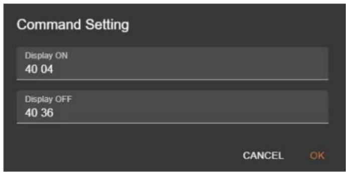
- Click the icon to display the Command Setting fields.
text_image
Command Setting Display ON 40 04 Display OFF 40 36 CANCEL OK- Enter the power-on and power-off commands in the Display ON and Display OFF fields, respectively. Consult the documentation for the display for the correct command strings.

NOTE: The CEC commands currently set in the Command Setting fields should work with most display manufacturers.
- Click the OK button to save changes.
- Click the DISPLAY ON and DISPLAY OFF buttons to verify that each command works properly. If not, check the values entered for each command.
System Maintenance
Updating the Firmware
- Log in to the web server.
- Click Maintenance in the side menu bar.
- Click System in the top menu bar.

text_image
ATLONA Maintenance System Log Power Saving Firmware Model MAC Address IP Address AT PROS A0010 BE 96.00 (E PE 45) IP 20.20 87 Firmware Version: XAM_13.0 MCU_3.69 CPU8_18.8 TPGA_169 AWP_2.10 AWG_2.10 AWZ_2.10 AWR_2.10 Recover Firmware Version: RX1.MCU_11.2 RX2.MCU_11.2 RX3.MCU_11.2 RX4.MCU_11.2 RX5.MCU_11.2 Log Files + download status Note: log export may take train- Under the Firmware window group, all firmware versions will be listed. If there are AT-PRO5-101-RX and/or AT-PRO5-101-SC-RX receivers connected to the AT-PRO5-MX810, then the receiver firmware version will also be listed.
- Click the UPDATE button.
- The Open dialog will be displayed. Locate the firmware file and click the Open button.
Downloading Log Files
This feature allows log files to be downloaded to the local PC. Log files are used for troubleshooting purposes and may be requested by Atlona Technical Support Engineers.
- Log in to the web server.
- Click Maintenance in the side menu bar.
- Click System in the top menu bar.
- Under the Log Files window group, click the DOWNLOAD button. Log files are automatically downloaded to the C:\Users\ [Username]\Downloads folder on the PC.
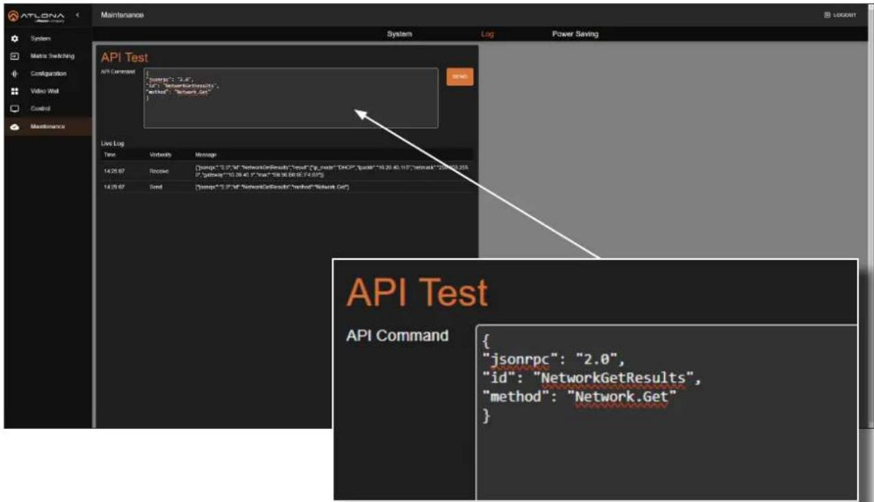
API Testing
This page provides testing of JSON-RPC 2.0 commands.
- Log in to the web server.
-
Click Maintenance in the side menu bar.
-
Click Log in the top menu bar.
text_image
ATLONA Maintenance System Log Power Saving System Metric Switching Configuration Video Wall Control Maintenance API Test API Command { "jsonrpc": "2.0", "id": "NetworkGetResults", "method": "Network.Get" } Live Log Time Verbend Message 14:25:97 Rebuild {"jsonrpc": "2.0", "networkGetResults", "method": "id", "code": "DHCP", "sumA": "10.39.40, 11.8", "network": "200000.200000.200000.200000.200000.200000.200000.200000.200000.200000.200000.200000.200000.200000.200000.2.56" {"getvalue": "10.39.40, "Total": "58.36 BB(E:74.84%)" 14:25:97 Send {"jsonrpc": "2.0", "networkGetResults", "method": "Network.Get" } API Test API Command {"jsonrpc": "2.0", "id": "NetworkGetResults", "method": "Network.Get" }-
Enter the JSON string in the API Command field.
-
Click the SEND button. If the JSON-RPC 2.0 command is valid, feedback will be displayed under the Live Log section.
Device Operation
Power Saving
To conserve power, the AT-PRO5-MX810 provides the ability to disable the PoE function for ports EXT 1 - EXT 8 (RJ45) when they are not in use. Additionally, it supports monitoring the operating status of remote SDVoE receivers.
- Log in to the web server.
- Click Maintenance in the side menu bar.
- Click Power Saving in the top menu bar.
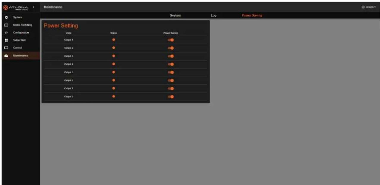
text_image
ATLONA Maintenance System Log Power Saving Power Setting Date Status Power Settings Output 1 Output 2 Output 3 Output 4 Output 5 Output 6 Output 7 Output 8- Click the Power Saving toggle switch for each output to enable or disable power saving. When enabled, the Power Saving toggle switch will be orange.
Appendix
Specifications
| Video | ||
| Signal Input – HDMI | Output – SDVoE (RJ45, SFP+) | |
| Copy Protection HDCP 1.4 / 2.2 / 2.3 | ||
| Pixel Clock 600 MHz | ||
| UHD/HD/SD 4096x2160 @ 60/50 | 3840x2160 @ 60/50/30/25/24 Hz1920x1080p @ 60/59.9/50/30/29.97/25/24/23.98 Hz1920x1080i @ 30/29.97/25 Hz1280x720p @ 60/59.94/50 Hz | 720x576p @ 50 Hz720x576i @ 25 Hz640x480p @ 60/59.96 Hz640x480i @ 30 Hz |
| VESA 2560×1600 | 1360×7681280×10241280×8001152×8641024×768800×600640×480 | |
| 2048×15361920×12001680×10501600×12001440×9001400×10501366×768 | ||
| Color Space YUV, RGB | ||
| Chroma Subsampling 4:4:4, 4:2:2, 4:2:0 | ||
| Color Depth 8-bit, 10-bit, 12-bit | ||
| HDR HDR10, Hybrid-Log Gamma (HLG), and Dolby | ® VisionTM @ up to 60 Hz | |
| Audio | |||
| HDMI Pass-Through Formats L | PCM 2.0LPCM 5.1LPCM 7.1 | Dolby®DigitalDolby Digital PlusTMDolby TrueHDDolby Atmos® | DTS®Digital SurroundTMDTS-HD Master AudioTMDTS:X® |
| Bit Depth Up to 24 bits | |||
| Sample Rate 32 kHz, 44.1 kHz, | 48 kHz, 88.2 kHz, 96 kHz, 176.4 kHz, 192 kHz | ||
| Analog Audio | |||
| Format Stereo 2-Channel | |||
| Type Balanced Audio | |||
| Ethernet | |
| Port | 1 x RJ45 |
| Standards and Protocols | HTTP, HTTPS, Telnet, SSH, mDNS |
| Speeds | 10/100/1000 Mbps |
| Addressing | DHCP, Static, APIPA |
| RS-232 | ||
| Port | 1 x 3-pin captive screw, TX, RX, GND | |
| Use | Device control and configuration | |
| Baud Rates | 2400, 4800, 9600, 19200, 38400, 57600, 115200 | |
| Data Flow | Bidirectional | |
Appendix
| CEC | |
| Ports 2 x HDMI OUT, Type A, 19-pin female | |
| Triggering IP, RS-232, and built-in web server | |
| Resolution / Distance 4K/UHD - Feet / Meters 1080p - Feet / Meters | ||||
| HDMI IN/OUT 15 5 30 10 | ||||
| CAT6a 330 100 330 100 | ||||
| Buttons and Indicators | |
| Buttons: | |
| RESET | 1 x momentary, recessed |
| Indicators: | |
| PWR | 1 x LED, blue |
| STATUS | 1 x LED, blue/red/off |
| Connectors | |
| INPUT 8 x Type A, 19-pin female | |
| OUTPUT 2 x Type A, 19-pin female | |
| EXT 1 - 8 (SDVoE) 8 x RJ45, female | |
| 8 x SFP+ cage, female | |
| RS-232 | 1 x 3-pin captive screw |
| LAN | 1 x RJ45, 1000Base-T |
| IR IN | 8 x 3.5 mm jack, female |
| IR OUT | 8 x 3.5 mm jack, female |
| AUDIO OUT | 8 x 5-pin captive screw, balanced / unbalanced, 2-channel |
| AC100-240V 50/60 Hz | IEC |
| Environmental | Fahrenheit | Celsius | ||
| Operating Temperature | +32 to +122 | 0 to +50 | ||
| Storage Temperature | -4 to +140 | -20 to +60 | ||
| Operating Humidity (RH) | 20% to 90%, non-condensing | |||
| Maximum Operating Altitude | 2000 meters | |||
| Power | ||
| Consumption (maximum) | 156.5 W | |
| Consumption (idle) | 43.8 W | |
| Consumption (operating) | 59 W | |
| BTU/h (maximum) 533.67 | ||
| BTU/h (idle) | 149.36 | |
| BTU/h (operating) | 201.19 |
| Dimensions (H x W x D) | Inches | Millimeters |
| Unit (2U) | 3.46 x 17.32 x 14.18 | 88.00 x 440.00 x 360.20 |
| Weight | Pounds | Kilograms |
| Device | 16.09 | 7.3 |
Appendix
| Certification | ||
| Device CE, FCC, RoHS | ||
| Power Supply CE, FCC, RoHS, CCC, CB | ||
| Compliance | ||
| NDAA-889 Yes | ||
| TAA No | ||
| Warranty | ||
| 3 years View the full warranty information here: https://atlona.com/warranty | ||