AT-HDR-SW-52ED - Switch Atlona - Free user manual and instructions
Find the device manual for free AT-HDR-SW-52ED Atlona in PDF.


| Product Type | HDMI Switch |
| Model | AT-HDR-SW-52ED |
| Brand | Atlona |
| Number of Inputs | 5 |
| Number of Outputs | 2 |
| Maximum Resolution | 4K@60Hz 4:4:4 |
| HDR Support | Yes (HDR10, Dolby Vision, HLG) |
| HDMI Standard | HDMI 2.0 |
| HDCP Support | HDCP 2.2 |
| EDID Management | Internal and external EDID |
| Control | IR, RS-232, TCP/IP, front panel |
| Dimensions (W x D x H) | 220 x 160 x 25 mm |
| Weight | 0.5 kg |
| Power Supply | 5V DC, 2A |
| Power Consumption | 5W (max) |
| Operating Temperature | 32°F to 104°F (0°C to 40°C) |
| Storage Temperature | -4°F to 140°F (-20°C to 60°C) |
| Safety | Do not expose to liquid; use only supplied power adapter |
| Maintenance | Clean with dry cloth; avoid solvents |
| Spare Parts & Repairability | Power adapter available; no user-serviceable parts inside |
| General Information | Designed for professional AV integration; supports seamless switching |
Frequently Asked Questions - AT-HDR-SW-52ED Atlona
User questions about AT-HDR-SW-52ED Atlona
0 question about this device. Answer the ones you know or ask your own.
Ask a new question about this device
Download the instructions for your Switch in PDF format for free! Find your manual AT-HDR-SW-52ED - Atlona and take your electronic device back in hand. On this page are published all the documents necessary for the use of your device. AT-HDR-SW-52ED by Atlona.
USER MANUAL AT-HDR-SW-52ED Atlona
with HDMI and HDBaseT Outputs
Version Information
Version Release Date Notes
3 Jan 2024 Updated warranty information
Sales, Marketing, and Customer Support
Main Office
Atlona Incorporated
70 Daggett Drive
San Jose, CA 95134
United States
Office: +1.408.962.0515
Sales and Customer Service Hours
Monday - Friday: 6:00 a.m. - 4:30 p.m. (PST)
https://atlona.com/
International Headquarters
Atlona International AG
Tödistrasse 18
8002 Zürich
Switzerland
Office: +41.43.508.4321
Sales and Customer Service Hours
Monday - Friday: 09:00 - 17:00 (UTC +1)
Operating Notes

IMPORTANT: Visit https://www.atlona.com/product/at-hdr-sw-52ed for the latest firmware updates and User Manual.
Warranty

To view the product warranty, use the following link or QR code:
https://atlona.com/warranty/.
Safety and Certification
CAUTION
RISK OF ELECTRIC SHOCK
DO NOT OPEN
CAUTION: TO REDUCT THE RISK OF
ELECTRIC SHOCK
DO NOT OPEN ENCLOSURE OR EXPOSE
TO RAIN OR MOISTURE.
NO USER-SERVICEABLE PARTS
INSIDE REFER SERVICING TO
QUALIFIED SERVICE PERSONNEL.

The exclamation point within an equilateral triangle is intended to alert the user to the presence of important operating and maintenance instructions in the literature accompanying the product.

The information bubble is intended to alert the user to helpful or optional operational instructions in the literature accompanying the product.
- Read these instructions.
- Keep these instructions.
- Heed all warnings.
- Follow all instructions.
- Do not use this product near water.
- Clean only with a dry cloth.
- Do not block any ventilation openings. Install in accordance with the manufacturer's instructions.
-
Do not install or place this product near any heat sources such as radiators, heat registers, stoves, or other apparatus (including amplifiers) that produce heat.
-
Do not defeat the safety purpose of a polarized or grounding-type plug. A polarized plug has two blades with one wider than the other. A grounding type plug has two blades and a third grounding prong. The wide blade or the third prong are provided for your safety. If the provided plug does not fit into your outlet, consult an electrician for replacement of the obsolete outlet.
- Protect the power cord from being walked on or pinched particularly at plugs, convenience receptacles, and the point where they exit from the product.
- Only use attachments/accessories specified by Atlona.
- To reduce the risk of electric shock and/or damage to this product, never handle or touch this unit or power cord if your hands are wet or damp. Do not expose this product to rain or moisture.
- Unplug this product during lightning storms or when unused for long periods of time.
- Refer all servicing to qualified service personnel. Servicing is required when the product has been damaged in any way, such as power-supply cord or plug is damaged, liquid has been spilled or objects have fallen into the product, the product has been exposed to rain or moisture, does not operate normally, or has been dropped.


FCC Compliance
FCC Compliance and Advisory Statement: This hardware device complies with Part 15 of the FCC rules. Operation is subject to the following two conditions: 1) this device may not cause harmful interference, and 2) this device must accept any interference received including interference that may cause undesired operation. This equipment has been tested and found to comply with the limits for a Class A digital device, pursuant to Part 15 of the FCC Rules. These limits are designed to provide reasonable protection against harmful interference in a commercial installation. This equipment generates, uses, and can radiate radio frequency energy and, if not installed or used in accordance with the instructions, may cause harmful interference to radio communications. However there is no guarantee that interference will not occur in a particular installation. If this equipment does cause harmful interference to radio or television reception, which can be determined by turning the equipment off and on, the user is encouraged to try to correct the interference by one or more of the following measures: 1) reorient or relocate the receiving antenna; 2) increase the separation between the equipment and the receiver; 3) connect the equipment to an outlet on a circuit different from that to which the receiver is connected; 4) consult the dealer or an experienced radio/TV technician for help. Any changes or modifications not expressly approved by the party responsible for compliance could void the user's authority to operate the equipment. Where shielded interface cables have been provided with the product or specified additional components or accessories elsewhere defined to be used with the installation of the product, they must be used in order to ensure compliance with FCC regulations.
Copyright, Trademark, and Registration
© 2024 Atlona Inc. All rights reserved. "Atlona" and the Atlona logo are registered trademarks of Atlona Inc. Pricing, specifications and availability subject to change without notice. Actual products, product images, and online product images may vary from images shown here.

The terms HDMI, HDMI High-Definition Multimedia Interface, HDMI trade dress and the HDMI Logos are trademarks or registered trademarks of HDMI Licensing Administrator, Inc.
Dolby, Dolby Atmos, and the double-D symbol are registered trademarks of Dolby Laboratories Licensing Corporation.
For DTS patents, see http://patents.dts.com. Manufactured under license from DTS, Inc. DTS, the Symbol, DTS and the Symbol together, and Digital Surround are registered trademarks and/or trademarks of DTS, Inc. in the United States and/or other countries. © DTS, Inc. All Rights Reserved.
All other trademark(s), copyright(s), and registered technologies mentioned in this document are the properties of their respective owner(s).
Table of Contents
Introduction 7
Features 7
Package Contents 7
Panel Description 8
Front Panel 8
Rear Panel 9
Installation 10
Power 10
Connection Instructions 10
Connection Diagram 11
IP Configuration 12
Using the Front Panel 12
Using the Web Server 13
Setting the IP Address Using Commands 13
Automatic Private IP Addressing (APIPA) Mode 14
Device Operation 15
LED Indicators 15
Logging in to the Web Server 16
Login Registration 16
Logging in after Registration 17
Switching Modes 18
Mirrored Mode 18
Matrix Mode 19
Auto Switching 21
Enabling / Disabling Auto Switching 21
Scaler Pass-Through 22
Notes on Scaling 23
Audio Management 24
HDMI / HDBaseT Audio Muting 24
Analog Audio Output 25
S/PDIF Audio Muting 27
S/PDIF Audio Muting from RX 28
HDCP Content 29
RS-232 Control 30
Console Mode 30
Pass-Through Mode 31
IR Control 32
Controlling Display Devices 32
Controlling Source Devices 33
Display Control 34
Using CEC 34
RS-232 Configuration 37
IP Configuration 39
Completing RS-232 or IP Configuration 41
EDID Management 44
Using the Downstream EDID 44
EDID Presets 45
Storing EDID Data 46
User Management 49
Table of Contents
System Configuration 50
Getting the MAC Address 50
Changing the Network IP Mode 50
Changing the Telnet Port 51
Telnet Login Mode 52
Telnet Timeout 52
Broadcast
Setting the Host Name 53
Locking / Unlocking the Front Panel 54
Resetting to Factory Defaults 55
Using the Web Server 55
Using the Front Panel 56
Configuration and Management Interfaces 57
Web Server 57
Register page 57
Login page 58
Info page 59
A/V Settings page 60
Display page 62
RS-232 page 67
EDID page 68
Config page 69
System page 70
HDBT page 73
Appendix
Updating the Firmware 74
Using the Web Server 74
Using USB 75
Mounting Instructions 76
Single Unit Rack Installation 76
Dual Unit Rack Installation 77
Flat Surface 78
Specifications 79
Introduction
The Atlona AT-HDR-SW-52ED is a 5×2 HDMI matrix switcher for high dynamic range (HDR) formats. Part of the comprehensive family of Atlona 4K HDR integration products, it features five HDMI inputs and matrixed or mirrored HDMI and HDBaseT outputs. The HDBaseT output transmits video, embedded audio, and Ethernet over distances up to 330 feet (100 meters) to the AT-HDR-EX-100CEA-RX receiver (available separately). The HDR-SW-52ED is HDCP 2.2 compliant and supports 4K/UHD video @ 60 Hz with 4:4:4 chroma sampling, as well as HDMI data rates up to 18 Gbps. It is ideal for the latest as well as emerging 4K/UHD and HDR sources and displays, and includes EDID management features, automatic input switching, and automatic display control. Additionally, 4K downscaling to 1080p @ 60, 30, or 24 Hz is available for the outputs when connected to an HD display. The HDR-SW-52ED can de-embed audio from an HDMI input, or return audio from the HDR-EX-100CEA-RX receiver, to S/PDIF or balanced analog audio outputs. This HDMI switcher can be controlled via Ethernet, RS-232, and IR.
Features
- 5x2 HDMI matrix switcher
- HDBaseT and HDMI outputs with selectable AV switching modes
• Video, audio, power, and data over category cable utilizing HDBaseT technology - Selectable 4K to 1080p downscaling
• Automatic display control
• Automatic input selection using hot plug detect and video detection technology
• Audio de-embedding - Delivers return audio from the AT-HDR-EX-100CEA-RX receiver
Package Contents
1 x AT-HDR-SW-52ED
1 x Captive screw connector, 2-pin
1 x Captive screw connector, 3-pin
2 x Captive screw connector, 5-pin
1 x Long rack ear
1 x Short rack ear
2 x Mounting plates
4 x Mounting screws
4 x Rack screws
4 x Feet w/rubber grips
1 x 48 V / 0.83 A DC power supply
Panel Description
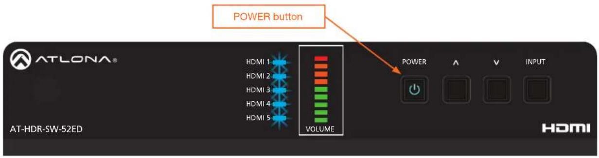
Front Panel

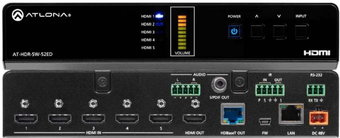
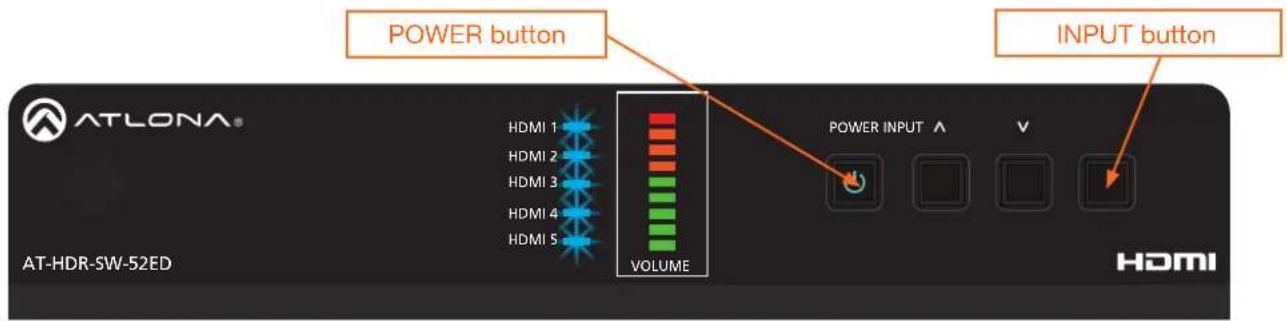
1 HDMI 1 - HDMI 5: Input LED Indicators
These LED indicators display which input is routed to the HDMI OUT port. A solid blue indicator represents the active input being used
2 VOLUME
Displays the output audio level. Refer to LED Indicators (page 15) for more information.
3 POWER
Press this button to toggle between "on" and "standby" power states. When in "standby", A/V is muted. When "on", A/V muting will be disabled.
4 Cursor Buttons
Press and release these buttons to increase or decrease the audio output volume on the ANALOG OUT port.
5 INPUT
Press and release this button to cycle through each of the HDMI inputs.
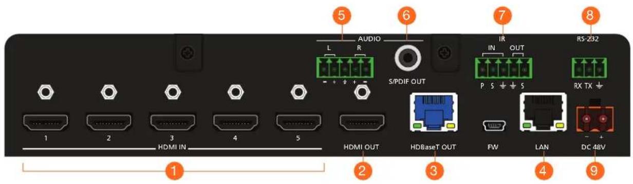
Rear Panel
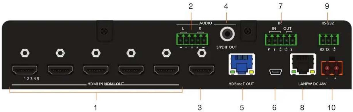
1 HDMI IN
Connect an HDMI cable from each of these ports to an HDMI source.
2 L/R
Connect an analog audio output device to this port using the included captive screw block. Refer to Analog Audio Output (page 25) for information on wiring.
3 HDMI OUT
Connect an HDMI cable from this port to an HDMI display.
4 AUDIO - S/PDIF OUT
Connect an RCA-type cable from this port to the S/PDIF audio input port on an A/V receiver or other audio output device.
5 HDBaseT OUT
Connect a category cable from this port to a the HDBaseT IN port of a compatible receiver unit.
6 FW
Connect a USB-to-mini USB cable to this port from a computer for firmware updates.
7 IR IN/OUT
Connect an IR emitter to the OUT (S, GND) pins to control a display using IR. Connect a control system to the IN (P, S, GND) pins. A 5-pin captive screw block is included.
8 LAN
Connect an Ethernet cable from this port to the Local Area Network (LAN). The AT-HDR-SW-52ED includes a built-in web server, which can be used to manage and configure the product.
9 RS-232
Connect the included captive screw block to an RS-232 controller to control the AT-HDR-SW-52ED.
10 DC 48V
Connect the included 48 V DC power supply from this power receptacle to an available AC electrical outlet. Refer to Power (page 10) for more information on wiring the included captive screw connector.
Installation
Power
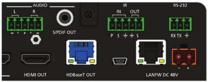
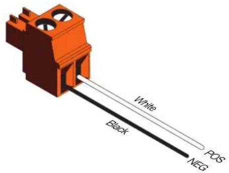
Connect the included 2-pin captive screw connector to the DC 48V power receptacle on the rear of the unit. The captive screw comes pre-wired as shown
Connection Instructions
- Connect a source device to each of the HDMI IN (1 - 5) ports.
- Connect a display device to the HDMI OUT port.
- Connect a category cable from the HDBaseT OUT port to a the HDBaseT IN port of a compatible receiver unit, such as the AT-HDR-EX-100CEA-RX.
- Connect an Ethernet cable from the LAN port to the Local Area Network (LAN). This step will be required in order to access the built-in web server.
- Connect the included 5-pin captive screw connector to the 5-pin AUDIO port. Refer to Analog Audio Output (page 25) for more information.
- Connect an RCA-type cable from the S/PDIF OUT port to an audio output device.
- Connect the included 5-pin captive screw connector to the 5-pin IR port to use IR control.
- Connect an RS-232 cable from the control system to the RS-232 port. Refer to RS-232 Control (page 30) for more information.
- Connect the included power supply to the DC 48V connector and connect the power cord to an available electrical outlet.
Installation
Connection Diagram
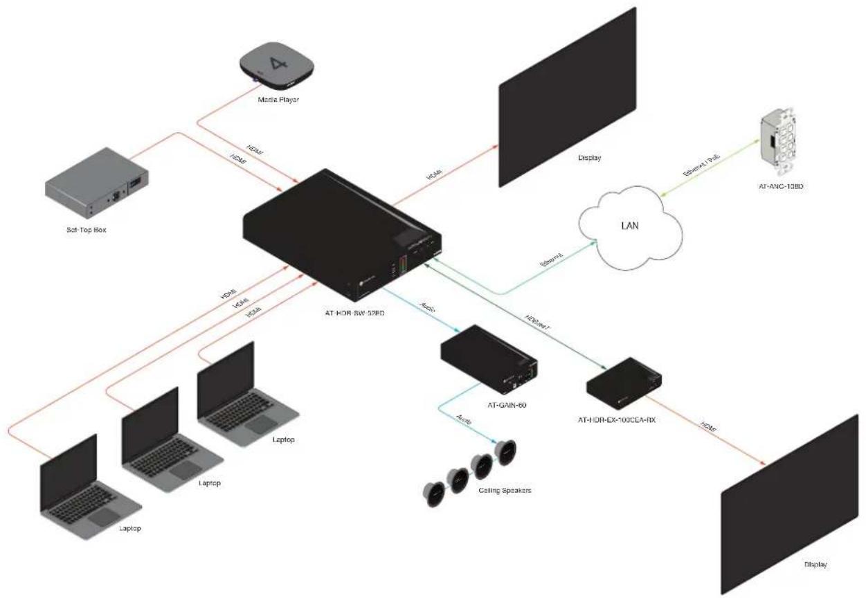
flowchart
graph TD
    A["Maria Player"] -->|HDMI| B["AT-HOR SW 32FD"]
    C["Sat Top Box"] --> B
    D["Laptop"] --> B
    E["Laptop"] --> B
    F["Laptop"] --> B
    G["AT-GAIN-60"] -->|LCD| H["AT-IDR-EX-100CEA-RX"]
    I["Ceiling Speakers"] -->|LCD| H
    J["Display"] -->|LAN| K["AT-ANC-13BD"]
    L["Display"] -->|LCD| M["AT-IDR-EX-100CEA-RX"]
    B -->|HDMI| N["Display"]
    B -->|LCD| O["AT-GAIN-60"]
    O --> P["Ceiling Speakers"]
    style B fill:#f9f,stroke:#333
    style H fill:#ccf,stroke:#333
    style M fill:#ccf,stroke:#333
IP Configuration
The AT-HDR-SW-52ED is shipped with DHCP enabled. Once connected to a network, the DHCP server (if available), will automatically assign an IP address to the unit. If the AT-HDR-SW-52ED is unable to detect a DHCP server within 15 seconds, then the unit will use a self-assigned IP address within the range of 169.254.xxx.xxx/16. If this occurs, refer to Automatic Private IP Addressing (APIPA) Mode (page 14).
Use an IP scanner, along with the MAC address on the bottom of the unit, to identify the unit on the network. If a static IP address is desired, the unit can be switched to static IP mode.

NOTE: When switching between DHCP and static IP mode, the AT-HDR-SW-52ED will retain the last assigned IP address until it is changed manually (static IP mode) or assigned a new IP address by the DHCP server.
Using the Front Panel
- Make sure the AT-HDR-SW-52ED is powered.
- Connect an Ethernet cable between the LAN port of the AT-HDR-SW-52ED and the Local Area Network (LAN).
- Press and hold the POWER button for approximately 15 seconds. Release the POWER button once all the front-panel LED indicators begin to flash. The number of flashes will indicate the currently selected IP mode. Refer to the table, below.
POWER Button flashes Description Settings
| Two Static IP mode IP address: | 192.168.1.254 | Subnet mask: 255.255.0.0Gateway: 192.168.1.1 |
| Four DHCP mode DHCP server | assigned |
Installation
Using the Web Server
The IP mode of the AT-HDR-SW-52ED can also be set using the built-in web server. In order to access the web server, the IP address of the AT-HDR-SW-52ED must be known.
- Open the desired web browser and enter the IP address of the AT-HDR-SW-52ED.
- Log in using the required credentials.
- Click System in the menu bar.
- Click the IP Mode toggle to switch between the DHCP and STATIC IP setting. When set to STATIC IP, the IP, Netmask, and Gateway fields can be modified.
- Click the Save button to save the changes.
Network
MAC Address: B8-98-B0-07-44-36
IP Mode: STATIC IP
IP: 10.20.20.31
Netmask: 255.255.255.0
Save
Setting the IP Address Using Commands
Use the IPStatic and IPDHCP commands to switch between DHCP and IP mode through RS-232 or Telnet. Refer to API documentation for more information.

IMPORTANT: When switching between DHCP and static modes, within a Telnet session, the connection will be terminated once the IPDHCP command is executed.
- Setting static IP mode
- Connect to the AT-HDR-SW-52ED using RS-232 or Telnet.
- Execute the IPStatic command. This command requires three arguments: the desired IP address of the AT-HDR-SW-52ED, the subnet mask, and the gateway address. All arguments must be entered in dot-decimal notation. The following is an example:
IPStatic 192.168.1.112 255.255.255.0 192.168.1.1
IP address Subnet mask Gateway
- Setting DHCP mode
-
Connect to the AT-HDR-SW-52ED using RS-232 or Telnet.
-
At the command line, execute the IPDHCP command using the on argument, as shown.
IPDHCP on
Once DHCP is enabled, the unit will be assigned an IP address by the DHCP server (if present).
Automatic Private IP Addressing (APIPA) Mode
If the AT-HDR-SW-52ED is unable to detect a DHCP server within 15 seconds, when set to DHCP mode, then Automatic Private IP Addressing (APIPA) will be used to assign the an address within the IPv4 address block 169.254.xxx.xxx/16. If a DHCP server is detected while in APIPA mode, then the AT-HDR-SW-52ED will be assigned an address from the DHCP server pool. To manually adjust the IP address, connect an Ethernet cable directly from the LAN port of the AT-HDR-SW-52ED to the LAN port of a computer, then do the following:
- Click Start > Settings > Control Panel > Network and Sharing Center.
- Click Change adapter settings.
- Right-click on the adapter that is used to establish a wired connection to the network, and select Properties from the context menu.
- Under the Ethernet Properties dialog box, select Internet Protocol Version 4 and then click the Properties button. Click the Use the following IP address radio button.

IMPORTANT: Before continuing, write down the current IP settings in order to restore them, later. If Obtain an IP address automatically and Obtain DNS server automatically are selected, then this step is not required.
-
Enter the desired static IP address or the IP address provided by the network administrator. If the computer does not require Internet access or if a statically-assigned IP address is being used, then an address within the IPv4 address block 169.254.xxx.xxx/16 can be entered.
-
Set the subnet mask to 255.255.0.0.
-
Click the OK button then close all Control Panel windows.
Device Operation
LED Indicators
The LED indicators on both the front and rear of the unit provide basic information on the current status of the AT-HDR-SW-52ED.
| LED Description | ||
| HDMI 1 - HDMI 5 | Solid blue The input is the currently selected (active) input. | |
| Off The input is not the active input. | ||
| VOLUME (dBFS) | Solid green Acceptable range for output volume. Audio should be free of clipping. If audio clipping is heard in this range, check the signal adjustment of the source device. | |
| Solid amber Audio signals that approach the 0 dBFS level are represented in this range. If audio clipping is heard, reduce the output gain of the source device until audio is free of distortion. | ||
| Solid red Audio signals which exceed 0 dBFS are represented in this range. Audio clipping occurs at this level. If clipping is heard, reduce the output gain of the source device until audio is free of distortion. | ||
| POWER Solid | blue Unit is powered and in normal operating mode. A/V muting is disabled. | |
| Solid red Unit is powered and in standby mode. In this mode, A/V will be muted. • Press the POWER button to place the unit in normal operating mode. | ||
| Off Unit is not powered. | • Check the power supply and make sure it is securely fastened to the captive screw connector on the rear of the unit. • Make sure that the power supply is connected to an available electrical outlet and that the outlet is “live” (some outlets are controlled by a wall switch). | |
| Flashing blue (slow) | Unit is in Update Mode. Refer to Updating the Firmware (page 74) for more information. | |
Logging in to the Web Server
Most of the AT-HDR-SW-52ED operation is handled through the built-in web server. In order to access the web server, the IP address of the unit must be known. Refer to IP Configuration (page 12) for more information.
Login Registration
Before the built-in web server can be accessed, a username and password must be created.
- Launch the desired web browser and enter the IP address of the AT-HDR-SW-52ED in the address bar.
- The AT-HDR-SW-52ED Register page will be displayed.

- Enter the desired username in the Username field. In the example above, the username admin is used.
- Enter the desired password in the Password field.

IMPORTANT: The password must contain a minimum of 8 characters, including one uppercase character, one lowercase character, and one number. Special characters are not permitted. Note that the Password and Confirm fields will be masked when entering the password.
- Verify the password by entering it in the Confirm field.
- Click the Submit button.
- The Login screen will be displayed.
Device Operation
Logging in after Registration
- Launch the desired web browser and enter the IP address of the AT-HDR-SW-52ED in the address bar.
- Enter the correct username and password in the respective fields.
- Click the Submit button.
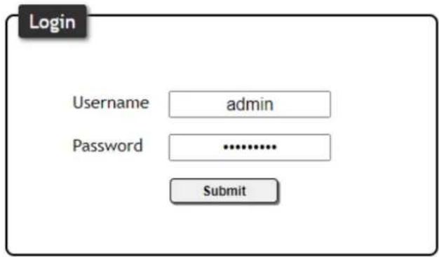
- The Info page will be displayed.
Switching Modes
The AT-HDR-SW-52ED features two switching modes: Mirrored and Matrix Mode. Each of these modes will be covered in the following section. Switching modes are configured using the built-in web server.
Mirrored Mode
This is the default mode. Once video is detected on the active input port, the output signal will be displayed on both the HDMI OUT and HDBaseT OUT port. The active input will be identified on the front panel HDMI LED input indicators and will be displayed as a solid green LED. Auto Switching (page 21) can also be enabled, if desired, to allow the AT-HDR-SW-52ED to automatically switch between inputs, if a new source is connected or an existing source is disconnected.
- Log in to the web server.
- Click A/V Settings in the menu bar.
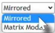
- Click the Switching Mode drop-down list and select Mirrored.
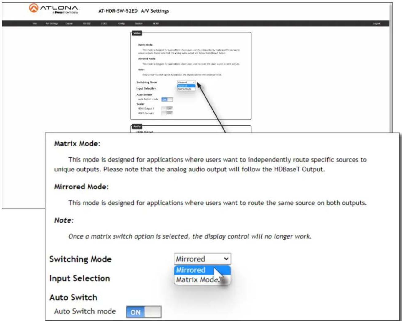
Device Operation
Matrix Mode
This mode allows the AT-HDR-SW-52ED to independently switch between any input to any output. Auto Switching is disabled in Matrix Mode. Audio on the L/R and S/PDIF OUT ports will always follow HDBaseT OUT while the AT-HDR-SW-52ED is in Matrix Mode.
- Log in to the web server.
- Click A/V Settings in the menu bar.
- Click the Switching Mode drop-down list and select Matrix Mode.

IMPORTANT: If the AT-HDR-SW-52ED is set to Matrix Mode, then Auto Switching will be disabled.
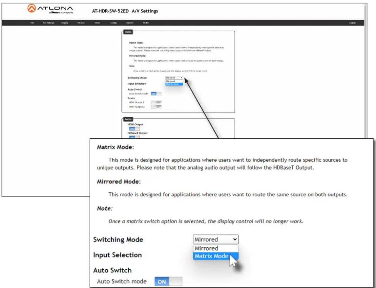
- Click the Matrix Mode HDMI Source drop-down list and select the input to be routed to the HDMI OUT port.
Matrix Mode:
This mode is designed for applications where users want to independently route specific sources to unique outputs. Please note that the analog audio output will follow the HDBaseT Output.
Mirrored Mode:
This mode is designed for applications where users want to route the same source on both outputs.
Note:
Once a matrix switch option is selected, the display control will no longer work.
Switching Mode
Matrix Mode HDMI Source
Matrix Mode HDBaseT Source
Scaler
HDMI Output 1
HDBT Output 2
Matrix Mode
- Click the Matrix Mode HDBaseT Source drop-down list and select the input to be routed to the HDBaseT OUT port.
Auto Switching
The AT-HDR-SW-52ED provides Auto Switching capability, which is enabled by default. This feature will automatically switch the input to the most recently-connected source. If the active source is disconnected, then the input will automatically be switched to the previously-connected source.

IMPORTANT: The Auto Switching feature is only available when the Switching Mode is set to Mirrored mode. Refer to Switching Modes (page 18) for more information.
Enabling / Disabling Auto Switching
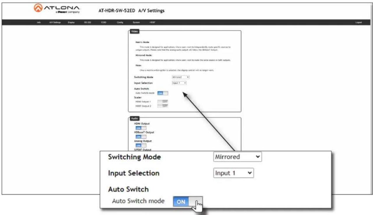
By default, Auto Switching is enabled on the AT-HDR-SW-52ED, allowing the unit to automatically switch between inputs when sources are connected or disconnected.
- Log in to the web server.
- Click A/V Settings in the menu bar.
-
Verify that the Switching Mode is set to Mirrored.
-
Click the Auto Switch mode toggle switch to the ON position to enable Auto Switching. This is the default setting. If Auto Switching is not desired, click this toggle switch to the OFF position. If the previously active input is no longer available, then the AT-HDR-SW-52ED will fallback to any available input.

NOTE: The AT-HDR-SW-52ED retains the currently selected input, even after the unit is powered off then powered on. The system should re-evaluate the Auto Switching logic after power on and select an input.
Scaler Pass-Through
Click this toggle switch to enable or disable the scaler pass-through feature. When set to the ON position, 4K content will be down-scaled to 1080p when the output device detects a 1080p display on the output. When set to the OFF position, the output resolution / timing will be the same as the input source. The default setting is OFF. Refer to Notes on Scaling (page 23) for more information.

IMPORTANT: The scaler will only downscale the image resolution and does not support frame rate scaling/conversion such as 60 Hz to 30 Hz. The frame rate of the source must be supported by the display device.
- Log in to the web server.
- Click A/V Settings in the menu bar.
- Click the HDMI Output 1 and/or HDBT Output 2 toggle switch to the ON position.
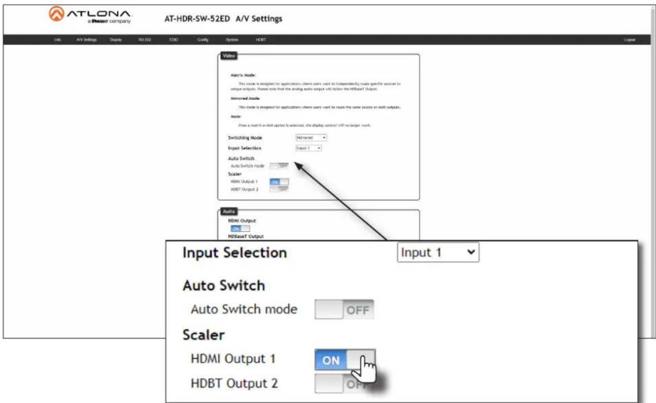
- The following message box will be displayed if either toggle switch is enabled. Click OK to dismiss the message box.
- Click the toggle switch again, to return the toggle switch to the OFF (default) position.
10.20.20.47 says
Frame rate of the source must be accepted by the scaled display. The scaler will only downscale resolution and not framerate. If you experience black screen this may be due to the frame rate not being supported

Device Operation
Notes on Scaling
The following section provides important information about how the AT-HDR-SW-52ED processes 4K (UHD) video signals.
• The HDMI OUT port supports up to 4K @ 60 Hz, 12-bit, with HDR.
- If the source is 4K, and the output port is connected to a 1080p (not 4K-capable) display, then the output will be down-scaled as follows:
| Input Output | ||
| 4K @ 24 Hz 1080p @ 24 Hz | ||
| 4K @ 30 Hz 1080p @ 30 Hz | ||
| 4K @ 60 Hz, 4:2:0 1080p @ 60 Hz, YUV/RGB 4:4:4 | ||
• HDR / Dolby Vision / HLG formats cannot be downscaled to 1080p.
- The internal scaler will be bypassed if the connected display supports the resolution and timing information from the source device.
Audio Management
The AT-HDR-SW-52ED provides volume control and independent audio muting. Audio muting can be controlled on the L/R, HDMI OUT, and HDBaseT OUT ports. To de-embed the source audio to the L/R port, connect the included 5-pin captive screw connector to the L/R port. De-embedding audio is restricted to two-channel Linear PCM formats.
HDMI / HDBaseT Audio Muting
- Log in to the web server.
- Click A/V Settings in the menu bar.
-
Locate the Audio section.
-
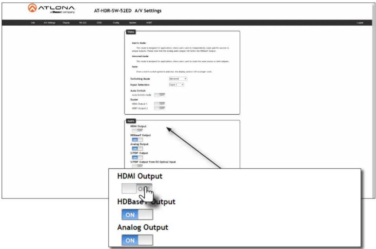
Click the toggle switch for the desired output. For example, to mute the audio output on the HDMI OUT or HDBaseT OUT port, click the associated toggle switch to the OFF position. To re-enable the audio for that output, set the toggle switch to the ON position.
Device Operation
Analog Audio Output
The AT-HDR-SW-52ED features a separate L/R port on the rear panel. This port provides de-embedding and conversion of two-channel LPCM audio streams to analog audio. Audio output volume can be controlled using API commands or the built-in web server.

IMPORTANT: The AT-HDR-SW-52ED will only de-embed two-channel LPCM audio. In addition, video must accompany the audio at all times. This product does not support audio-only ("free-run" mode) output.
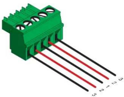
L/R Port Wiring
The included 5-pin captive screw block can be wired to support balanced audio using XLR connectors, or unbalanced audio using RCA connectors.
Balanced Audio (XLR)
| Channel Signal (AT-HDR-SW-52ED) Pin (XLR) | |
| R - 3 | |
| R + 2 | |
| -- GND* 1 | |
| L + 2 | |
| L - 3 | |
*The GND signal, from the 5-pin captive screw connector on the AT-HDR-SW-52ED, should be tied to pin 1 on both XLR connectors.
Unbalanced Audio (RCA)
| Channel Signal (AT-HDR-SW-52ED) Pin (RCA) | |
| R to GND* -- | |
| R++ | |
| -- GND GND | |
| L++ | |
| L to GND* -- |
*The GND signal, from the captive screw connector on the AT-HDR-SW-52ED, should be tied to L- and R- on the captive screw connector.
natural_image
3D diagram of a green terminal block with three black leads and red lines, labeled G3, D2, H3, G5 (no text or symbols on the components)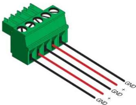
natural_image
Green electrical connector with three pins and three red/green wires, no text or symbols visibleDe-Embedding Audio
- Log in to the web server.
- Click A/V Settings in the menu bar.
- Locate the Audio section.
- Click the Analog Output toggle switch to the ON position. To mute the audio on the L/R port, click this toggle switch to the OFF position.
- Under Analog Audio Output Volume, click and drag the slider to adjust the audio output level. The current output volume, in decibels, will be displayed in the Analog Output field, next to the slider bar. Audio output level can be set within the range of -90 dB to +10 dB. The default settings is 0 dB.
The decibel value can also be entered directly in the Analog Output field, instead of using the slider.

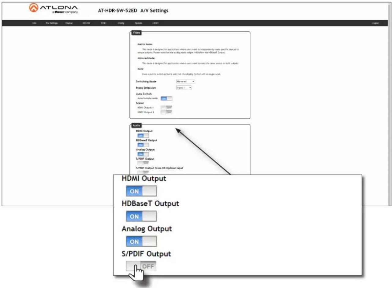
S/PDIF Audio Muting
- Log in to the web server.
- Click A/V Settings in the menu bar.
-
Locate the Audio section.
-
Click the S/PDIF Output toggle switch to the OFF position. To re-enable the audio on the S/PDIF OUT port, set the toggle switch to the ON position.
S/PDIF Audio Muting from RX
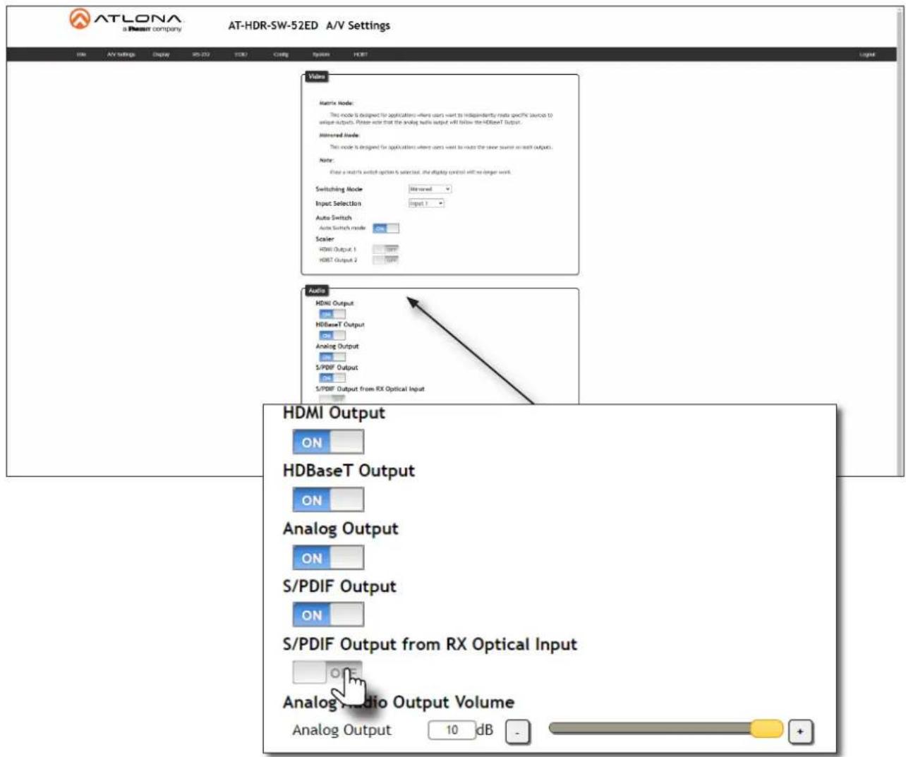
This feature allows muting of the optical input on the receiver (AT-HDR-EX100-CEA-RX).
- Log in to the web server.
- Click A/V Settings in the menu bar.
-
Locate the Audio section.
-
Click the S/PDIF Output from RX Optical Input toggle switch to the OFF position. To re-enable the audio on the optical port of the receiver, set the toggle switch to the ON position.
HDCP Content
Transmitting HDCP content to a display that is not HDCP compliant can result in "snow", image flickering, or no picture. In the illustration below, a laptop source is connected to the AT-HDR-SW-52ED, which is connected to a display that is not HDCP compliant.

IMPORTANT: Not all source devices are capable of transmitting non-HDCP content.
For example, Sony PlayStation ^® gaming consoles and Mac ^® computers always transmit HDCP-encrypted content.

flowchart
graph LR
    A["Non-Compliant HDCP Display"] -->|H3.3e| B["AT-HOR-SW-52ED"]
    B -->|H3.4e| C["Laptop"]
By default, the laptop may transmit HDCP content. However, when connected to a display that does not support HDCP, the laptop must be instructed to send non-HDCP content in order for the content to be displayed.
- Log in to the web server.
- Click A/V Settings in the menu bar.
-
Locate the HDCP section.
-
Click the toggle switch next to the desired input. In this example, clicking the Input 1 toggle switch and setting it to the OFF position will instruct the source device to send non-HDCP content, if possible.
HDCP
HDCP Settings
Input 1
Input 2
Input 3
Input 4
Input 5




If the display is unable to receive HDCP content, then a "black screen" with no image will be displayed.
RS-232 Control
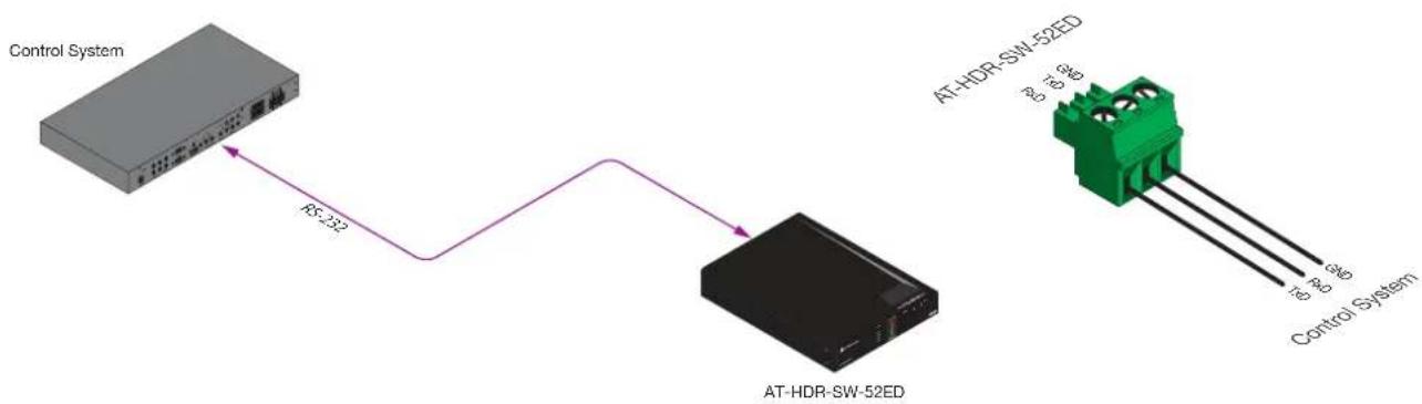
The RS-232 port is used to directly control the AT-HDR-SW-52ED using a control system (Console Mode) or can be used to send commands to the AT-HDR-SW-52ED, from a control system, to the display/sink device over HDBaseT (Pass-Through Mode).
Console Mode
-
Connect the RS-232 cable between the control system and the RS-232 port on the AT-HDR-SW-52ED. The included 3-pin captive screw should be wired as shown.
-
Log in to the web server.
flowchart
graph LR
    A["Control System"] -->|RS-232| B["AT-HDR-SW-52ED"]
    B --> C["Control System"]
-
Click RS-232 in the menu bar.
-
Under the RS232 Console section, select the proper baud rate, data bit, parity, and stop bit settings. These settings must correspond with the control system RS-232 settings.
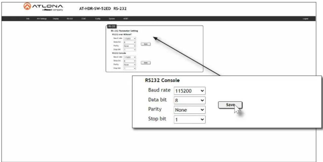
- Click the Save button to commit changes.
Pass-Through Mode
- Connect the RS-232 cable between the control system and the RS-232 port on the AT-HDR-SW-52ED. The included 3-pin captive screw should be wired as shown.
- Connect a category cable from the HDBaseT OUT port to a receiver (AT-HDR-EX-100CEA-RX).
- Connect an RS-232 cable between the display (sink) and the receiver.
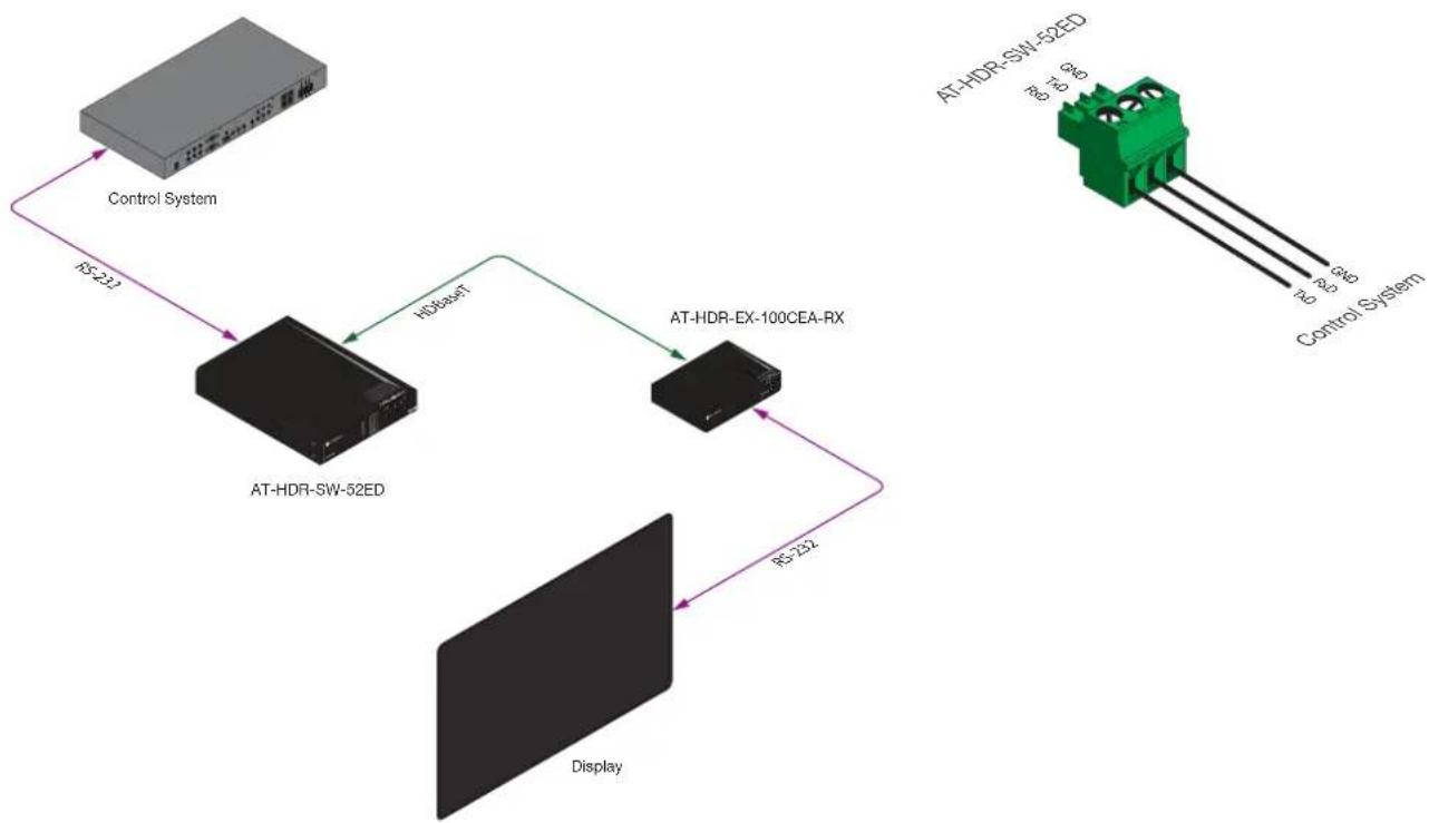
flowchart
graph TD
    A["Control System"] -->|RS-232| B["AT-HDR-SW-52ED"]
    B -->|HDba-sft| C["AT-HDR-EX-100CEA-RX"]
    C -->|RS-232| D["Display"]
    D -->|RS-232| B
    E["AT-HDR-SW-52ED"] -->|96 4 8 10| F["Control System"]
    style A fill:#ccc,stroke:#333
    style B fill:#999,stroke:#333
    style C fill:#999,stroke:#333
    style D fill:#999,stroke:#333
    style E fill:#ccc,stroke:#333
- Log in to the web server.
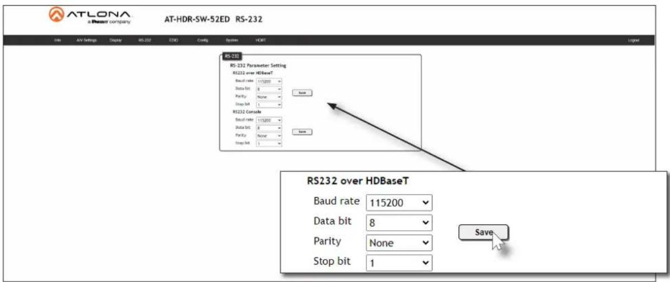
- Under the RS232 over HDBaseT section, select the proper baud rate, data bit, parity, and stop bit settings. These settings must correspond with the control system RS-232 settings.
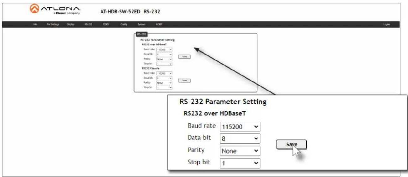
- Click the Save button to commit changes.
IR Control
IR can be used to control either headend or sink devices. IR is compatible with carrier frequencies from 30 kHz to 60 kHz.
Controlling Display Devices
- Remove at least 3/16" (5 mm) of insulation from the wire leads.
- Connect the included 5-pin captive screw connector to the IR IN/OUT port of the AT-HDR-SW-52ED. The included captive screw connector should be wired as shown.
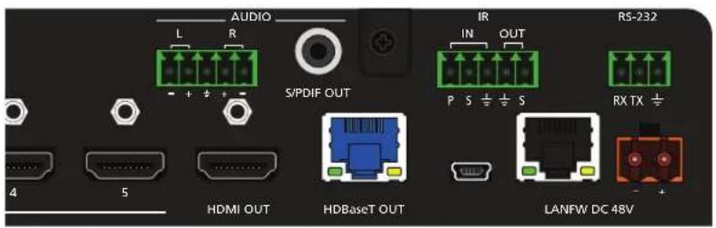
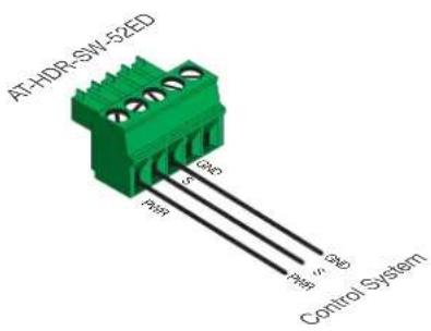
- Connect the IR emitter to the receiver and place the emitter next to the display (sink) device, as shown in the illustration below.
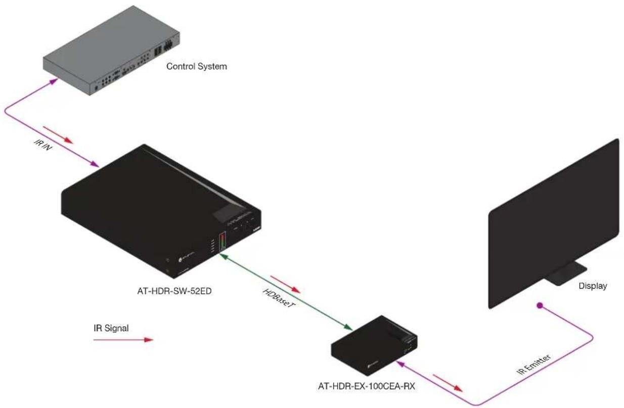
flowchart
graph TD
    A["Control System"] -->|IR/IN| B["AT-HDR-SW-52ED"]
    B -->|HDBsetT| C["AT-HDR-EX-100CEA-RX"]
    C -->|IR Emitter| D["Display"]
    B -->|IR Signal| E["Output"]
Controlling Source Devices
- Remove at least 3/16" (5 mm) of insulation from the wire leads.
- Connect the included 5-pin captive screw connector to the IR IN/OUT port of the AT-HDR-SW-52ED. The included captive screw connector should be wired as shown.
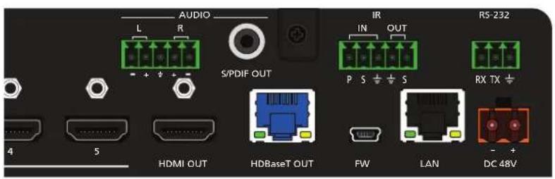
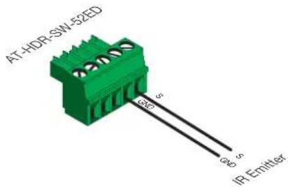
- Connect the IR emitter to the receiver and place the emitter next to the display (sink) device, as shown in the illustration below.
- Place the IR emitter next to the source device, as shown in the illustration below.

flowchart
graph LR
    A["Blu-ray Player"] -->|IR OUT| B["AT-HDR-SW-52ED"]
    B -->|HDset| C["AT-HDR-EX-100CEA-RX"]
    C -->|IR Receiver| D["Blu-ray Player IR Remote"]
    C -->|IR Signal| E["Output"]
Display Control
The AT-HDR-SW-52ED provides three protocols for display control: CEC, RS-232, and IP. No external control system is required. Each of these methods will be covered in this section.

IMPORTANT: The AT-HDR-SW-52ED Switching Mode must be set to Mirrored.
Display control is not supported under Matrix Mode. Refer to Switching Modes (page 18) for more information.
Using CEC
Consumer Electronics Control ^+ (CEC) is the simplest method of control when working with a display. The POWER button, on the front panel of the AT-HDR-SW-52ED, can be programmed to toggle power on the display, allowing for convenient remote control of the display device. Note that the display must have CEC enabled to receive CEC messages. Both the HDMI OUT and HDBaseT OUT ports can be used for CEC control. If using CEC control over HDBaseT, connect the HDMI cable from the receiver to the display.
*Atlona has confirmed proper CEC functionality with several current models of Samsung, Panasonic, and Sony displays. However, it is not guaranteed that CEC will work with all displays. Many manufacturers do not support the CEC "off" command, and older displays use proprietary commands. Atlona only supports displays that use the CEC command structure defined in HDMI 1.2a. It is recommended that dealers request an evaluation product from Atlona, before designing a system using the CEC protocol. If this is not possible, then other control methods will need to be considered, in order to control displays using Atlona products.
- Connect an HDMI cable from the HDMI OUT port on the AT-HDR-SW-52ED (or receiver) to the HDMI input on the display device.
- Enable CEC on the display device. Refer to the documentation for the display device. It should be noted that different manufacturers will identify CEC with their own brand name. Refer to the table below.
Manufacturer CEC Designation
| Hitachi HDMI-CEC | |
| LG SIMPLINK | |
| Philips EasyLink | |
| Samsung AnyNet+ | |
| Sony BRAVIA Sync | |
| Toshiba CE Link / REGZA Link | |
| Visio HDMI-CEC |
- Log in to the web server.
- Click A/V Settings in the menu bar.
- Verify that the Switching Mode is set to Mirrored. Display control is not supported under Matrix Mode.
Mirrored Mode:
This mode is designed for applications where users want to route the same source on both outputs.
Note:
Once a matrix switch option is selected, the display control will no longer work.
Switching Mode
Input Selection
- Click Display in the menu bar.
- Under System Settings, click the Control Type drop-down list and select CEC. This is the default control method.
System Settings
Display Auto Power
Active Video Presence
Auto power off timer
15 Seconds
Lamp cool down timer
10 Seconds
Display Warm-Up Timer
10 Seconds
Control Type
CEC

- Under the CEC section, near the top of the page, test the CEC commands for power, volume, and input by clicking the associated buttons. The display should respond correctly to each of these commands.
CEC
CEC Command - HDBaseT Output
Power
ON
OFF
Volume


MUTE
Input
INPUT
CEC Command - HDMI Output
Power
ON
OFF
Volume


MUTE
Input
INPUT
If the display does not respond, check the following:
- Verify that CEC is enabled on the display device.
- Verify the integrity of the HDMI cable. Try connecting a different cable between the AT-HDR-SW-52ED and the display device.
- If the display is connected to a receiver, such as the AT-HDR-EX-100CEA-RX, check both the HDMI cable from the receiver and the category cable between the HDBaseT OUT port on the AT-HDR-SW-52ED and the HDBaseT IN port on the receiver.
- Try connecting the HDMI cable to a different HDMI input on the display device.
Optional CEC Front Panel Button Control
To send power and volume commands to the display, using the POWER and VOLUME buttons on the front panel, following the instructions below:
- Click System in the menu bar.
- Click the Power button mode drop-down list and select CEC.
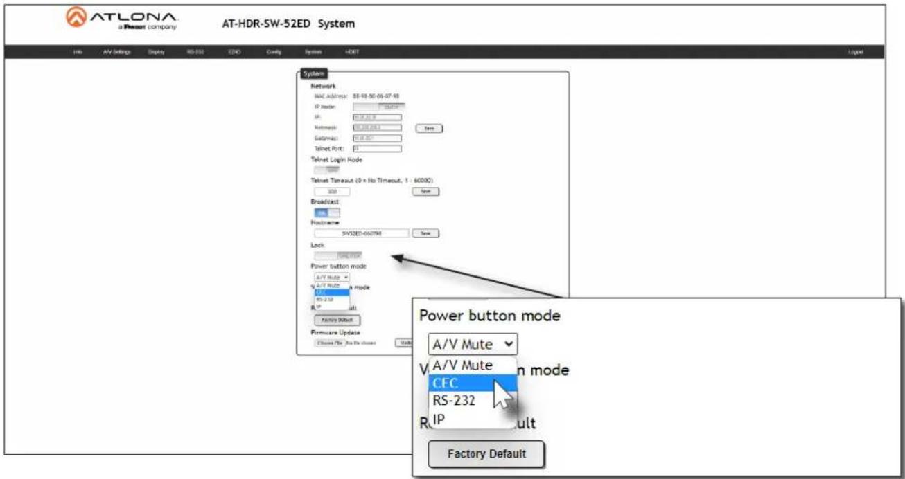
- To control volume on the display, click the Volume button mode drop-down list and select CEC.
RS-232 Configuration
- Connect a serial cable from the RS-232 port on the AT-HDR-EX-100CEA-RX, or compatible receiver, to the RS-232 port on the display. The included 3-pin captive screw connector should be wired as shown.

- Log in to the web server.
- Click A/V Settings in the menu bar.
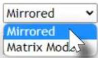
- Set the Switching Mode to Mirrored. Display control is not supported under Matrix Mode.
Mirrored Mode:
This mode is designed for applications where users want to route the same source on both outputs.
Note:
Once a matrix switch option is selected, the display control will no longer work.
Switching Mode
Input Selection
- Click RS-232 in the menu bar.
- Set the RS-232 settings for the display (sink) device, under the RS232 over HDBaseT section. These settings must match the device settings for the display. Refer to the User Manual of the display device for more information.
- Click Display in the menu bar.
- Under System Settings, click the Control Type drop-down list and select RS-232.
System Settings
Display Auto Power
Active Video Presence
Auto power off timer
15 Seconds
Lamp cool down timer
10 Seconds
Display Warm-Up Timer
10 Seconds
Control Type
RS-232

Optional RS-232 Front Panel Button Control
To send power and volume commands to the display, using the POWER and VOLUME buttons on the front panel, following the instructions below:
- Click System in the menu bar.
- Click the Power button mode drop-down list and select RS-232.

ATLONA
a Review company
AT-HDR-SW-52ED System
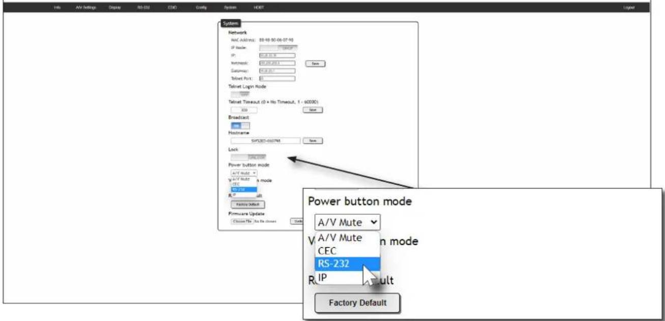
- To control volume on the display, click the Volume button mode drop-down list and select RS-232.
Device Operation
IP Configuration
Instead of using a serial cable to send commands, this method uses an Ethernet cable to send commands from the AT-HDR-SW-52ED to the display device over the network.
- Connect the display to the LAN.
- Log in to the web server.
- Click A/V Settings in the menu bar.
- Set the Switching Mode to Mirrored. Display control is not supported under Matrix Mode.
- Click Display in the menu bar.
- Under System Settings, click the Control Type drop-down list and select IP.
System Settings
Display Auto Power
Active Video Presence
Auto power off timer
15 Seconds
Lamp cool down timer
10 Seconds
Display Warm-Up Timer
10 Seconds
Control Type
IP

- Under TCP/IP Settings of Controlled Device, click the IP Mode drop-down list and select the desired mode. Selecting Login will display the Username and Password fields. If no login credentials are required, select the Non-Login option.
- Enter the IP address of the display in the IP Address field.
- Enter the port number in the Port field.
- Enter the username and password in the Username and Password fields, respectively. This option is only required if the IP Mode is set to Login.
TCP/IP Settings of Controlled Device
IP Mode
Login
IP Address
192.168.1.1
Port
23
Username
username
Password
●●●●●●●
Save
Optional IP Front Panel Button Control
To send power and volume commands to the display, using the POWER and VOLUME buttons on the front panel, following the instructions below:
- Click System in the menu bar.
- Click the Power button mode drop-down list and select IP.
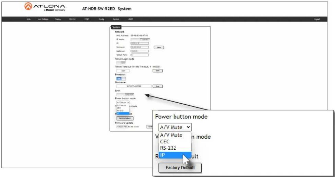
- To control volume on the display, click the Volume button mode drop-down list and select IP.
Completing RS-232 or IP Configuration
Once RS-232 or IP control has been configured, the commands for power, volume, muting, and volume will need to be assigned.
- Scroll down to the bottom of the page and locate the RS-232 / IP commands section.
- Click the Manufacturer drop-down list and select the manufacturer of the device that is being controlled. In the example below, Samsung is selected.
![Input INP Generic Acer Barco Benq Canon Casio Eiki Epson Display Auto Po Auto power off Hitachi Infocus Lg Nec Display Warm-U Optoma Panasonic Control Type Pjlink Planar Qomo Samsung Sharp Sony RS-232/IP comman Manufacturer Generic Products Generic Model Display Commands [Please use \x as a delimiter for HEX values] [Using a comma(,) will cause the transmission to pause for 5 seconds between commands. Multiple commas are acceptable to increase the amount of time.] Repeat Command Status ENABLED Times 2 ON PW 1 Send](/content/2026/05/1015092/images/fcbc91b5bebb501ad9646a3acdb1d87d61c3082959d2e9e0a897acc60a528b89.jpg)

NOTE: If the manufacturer is not listed in the drop-down list, then select Generic.
When Generic is selected, the Products and Model drop-down lists will be disabled.
Device Operation
- Continue fine-tuning the device selection by clicking the Products and Model drop-down lists. Once all fields have been set to the proper values, the AT-HDR-SW-52ED will populate the command fields with the proper values, based on the selected device.
- Some devices may require that the command be sent multiple times before an acknowledge message is received from the display. Refer to the User Manual for the display device for more information. If the command must be repeated, continue with the following steps. Otherwise, skip to Step 5.
a. Under Repeat Command, click the Status toggle switch to the ENABLED position.
b. Click the Times drop-down list and select the number of times which the command must be sent to the device, before an acknowledge message is returned. The available values are 2, 3, and 4.
RS-232/IP commands
Manufacturer
Samsung

Products
Samsung MDC Display

Model
All Models

Display Commands
[Please use \x as a delimiter for HEX values]
[Using a comma(,) will cause the transmission to pause for 5 seconds between commands. Multiple commas are acceptable to increase the amount of time.]
Repeat Command
Status
ENABLED
Times

ON

OFF

\xAA\x11\xFE\x01\x00\xBA
Send
Volume+
Send
Volume-
Send
Mute
\xAA\x13\xFE\x01\x00\xBC
Send
Mute on
\xAA\x13\xFE\x01\x01\xBD
Send
Mute off
Send
Save
Revert
- If Generic was selected as the manufacturer, then manually enter the required strings for each operation. Refer to the next page for information on formatting command strings.
Device Operation
HEX Command Strings
a. Enter the hexadecimal command string is the correct field. An example power-on command for a display might be:
\xBE\xEF\x03\x06\x00\xBA\xD2\x01\x00\x00\x60\x01\x00\x0D
This command would be entered in the ON field. Consult the documentation for the display for the correct command strings.
b. Make sure the command string is terminated correctly. In most cases, a CR (carriage return) should be specified. In the example above, × 0 is the hexadecimal value for a carriage return.
ASCII Command Strings
a. Enter the ASCII command string is the correct field. An example power-on command for a display might be:
PWON
This command would be entered in the ON field. Consult the documentation for the display for the correct command strings.
-
Click the Send button to verify that each command works properly. If not, check the values entered for each command.
-
Click the Save button to commit all changes.
EDID Management
Before a source can send picture and sound to a display device, the source reads the EDID (Extended Display Identification Data) stored in the display. The EDID contains information about what type of video and audio formats are supported by the display. The AT-HDR-SW-52ED can use either the downstream EDID (from the display/sink) or use a built-in EDID preset. EDID data can also be stored in any of eight EDID presets. This section will cover each of the following topics:
• Using the Downstream EDID
• EDID Presets
- Storing EDID Data
Using the Downstream EDID
By default, the AT-HDR-SW-52ED will read the EDID from the display device. The term “downstream” is used to describe any device that receives a signal from another device. For example, if a Blu-ray player is connected to a display, the display is said to be “downstream” of the Blu-ray player.
- Log in to the web server.
- Click EDID in the menu bar.
-
Locate the EDID Settings section.
-
Click the drop-down list, next to the input that is connected to the source device, and select Connected Display. For example, if HDMI IN 1 is connected to a source, click the Input 1 drop-down list and select Connected Display. The source device will read the EDID of the connected display and determine all supported video and audio formats.
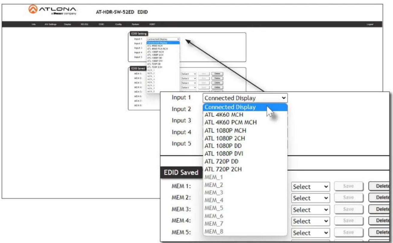
EDID Presets
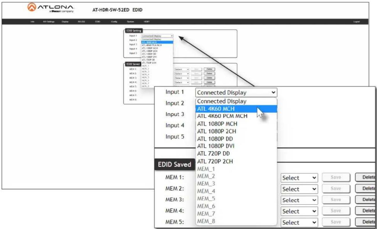
The AT-HDR-SW-52ED provides the option of selecting a preset EDID. The following presets are available.
| EDID Description | |
| Connected Display (Default) Uses the downstream EDID of the connected display | |
| ATL 4K60 MCH 3840 x 2160 (UHD) with multichannel audio support | |
| ATL 4K60 PCM MCH 3840 x 2160 (UHD) with PCM multichannel audio support | |
| ATL 1080P MCH 1920 x 1080p with multichannel audio support | |
| ATL 1080P 2CH 1920 x 1080p with two-channel audio support | |
| ATL 1080P DD 1920 x 1080p with Dolby | TM Digital audio support |
| ATL 1080P DVI 1920 x 1080p for DVI displays | |
| ATL 720P DD 1280 x 720p with Dolby | TM Digital audio support |
| ATL 720P 2CH 1280 x 720p with two-channel audio support | |
- Log in to the web server.
- Click EDID in the menu bar.
- Locate the EDID Settings section.
- Click the drop-down list, next to the port that is connected to the source device, and select the desired EDID preset. For example, if HDMI IN 1 is connected to the source, click the Input 1 drop-down list and select the desired EDID. The source device will use the selected EDID to determine all supported video and audio formats.

IMPORTANT: If problems are encountered when using an EDID preset, it is recommended that the input be set to Connected Display. Not all displays will support all video and audio formats in a given EDID preset.
Device Operation
Storing EDID Data
The AT-HDR-SW-52ED provides eight memory locations which can be used to store EDID data. Any downstream EDID can be captured and stored in these locations. Each memory location is non-volatile and captured EDID data is stored after power is disconnected from the unit.
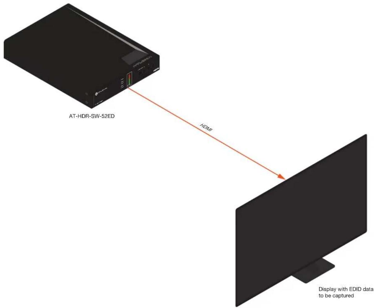
- Connect an HDMI cable from either HDMI OUT port on the AT-HDR-SW-52ED to the HDMI input on the display, containing the EDID to be stored.
- Log in to the web server.
-
Click EDID in the menu bar.
-
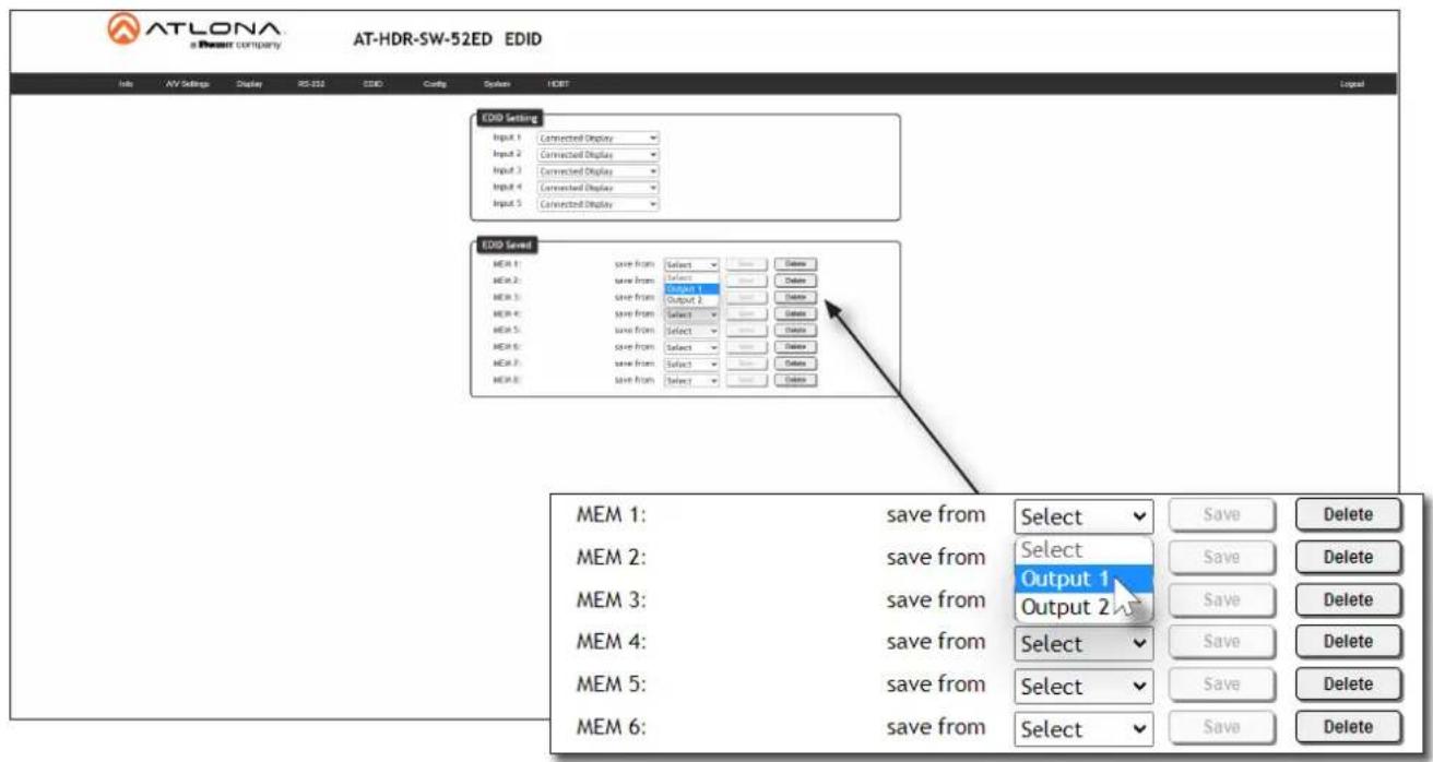
Locate the EDID Saved section.
-
Click the drop-down list, next to the memory location to be used, and select the output which will be used to fetch the EDID. Refer to the next page for more information.
In this example, MEM 1 (memory 1) will be used to store the EDID. Since the display is connected to the HDMI OUT 1 port on the AT-HDR-SW-52ED, Output 1 is selected from the MEM 1 drop-down list.
- Click the Save button next to the drop-down list for the memory location.
| MEM 1: | save from | Output 1 | Save | Delete |
| MEM 2: | save from | Select | Save | Delete |
| MEM 3: | save from | Select | Save | Delete |
| MEM 4: | save from | Select | Save | Delete |
| MEM 5: | save from | Select | Save | Delete |
| MEM 6: | save from | Select | Save | Delete |
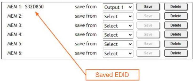
- The saved EDID will appear next to the memory location, as shown below.
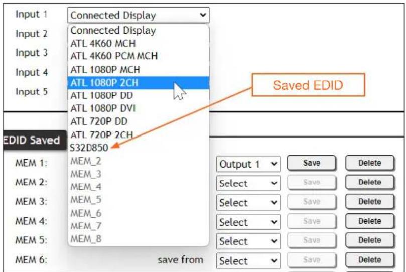
- Click any of the input drop-down list boxes. Note that the stored EDID appears as an available EDID preset for each available input on the AT-HDR-SW-52ED.

NOTE: Once an EDID is written to a memory location, it can be overwritten with a different EDID, when desired. To overwrite an EDID with a different EDID, repeat steps 5 through 7, above.
User Management
The AT-HDR-SW-52ED allows the login credentials to be changed. The username and password applies to both the web server and Telnet sessions.
- Log in to the web server.
- Click Config in the menu bar.
- Click the Old Username field and enter the current username.
- Click the Old Password field and enter the current password.

- Enter the new username in the New Username field.
- Enter the new password in the New Password field.
- Retype the new password in the Confirm New Password field.
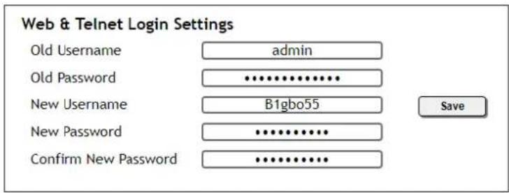

NOTE: Password fields will always be masked for security purposes.
- Click the Save button to commit changes. To login with the new username and password, click Logout in the upper-right corner of the screen, then enter the new login credentials on the Login page.
System Configuration
The AT-HDR-SW-52ED provides easy access to system configuration through the built-in web server, and is the recommended method to adjust network settings.
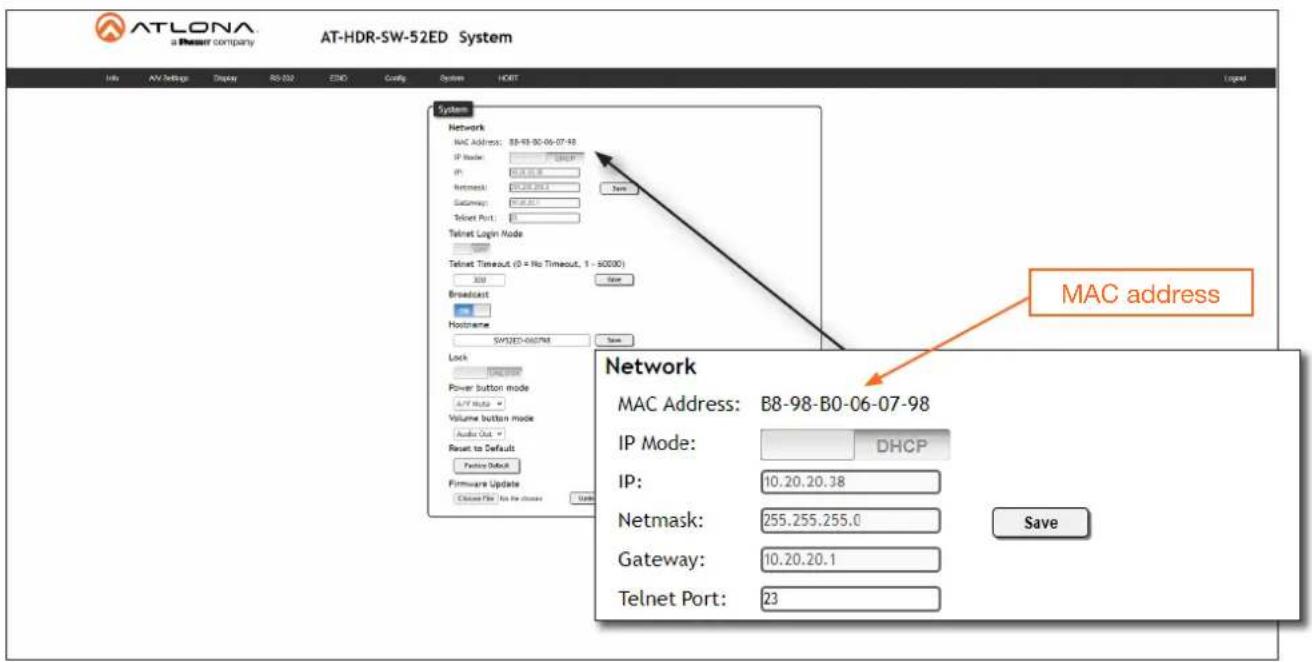
Getting the MAC Address
- Log in to the web server.
-
Click System in the menu bar.
-
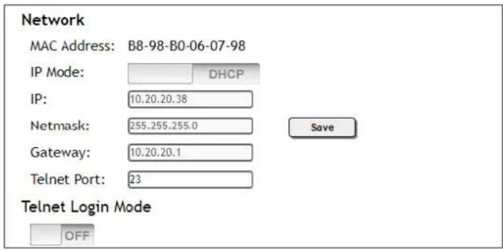
Locate the MAC address field, as shown below. This is the hardware address of the AT-HDR-SW-52ED.
Changing the Network IP Mode
By default, the AT-HDR-SW-52ED is set to DHCP mode. Once connected to a network, and if a DHCP server is found (or available), the AT-HDR-SW-52ED will be assigned an IP address on the network, and no further network configuration is required. However, if the AT-HDR-SW-52ED is unable to detect a DHCP server within 15 seconds, then the unit will use a self-assigned IP address within the range of 169.254.xxx.xxx/16. The instructions below will focus on setting the AT-HDR-SW-52ED to static IP mode.

IMPORTANT: Before assigning a static IP address to the AT-HDR-SW-52ED, it is recommended to consult with the network or system administrator and obtain a available IP address. Assigning the AT-HDR-SW-52ED to an IP address which is already in use can result in network issues or difficulty in accessing the AT-HDR-SW-52ED.
- Log in to the web server.
- Click System in the menu bar.
Device Operation
- Locate the IP Mode toggle switch. The default setting of this toggle switch is DHCP.
- Click this toggle switch to set it to STATIC IP.
- Enter the desired IP address for the AT-HDR-SW-52ED in the IP field.
- Enter the subnet mask and gateway (router) address in the Netmask and Gateway fields, respectively.
- Click the Save button to commit changes. Changes will take effect immediately.
Network
MAC Address: B8-98-B0-06-07-98
IP Mode:
IP:
Netmask:
Gateway:
Telnet Port:

Changing the Telnet Port
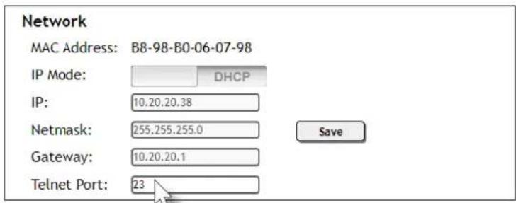
Typically, the Telnet service is assigned to TCP port 23. This is the default setting for the AT-HDR-SW-52ED. However, depending upon the network environment, the default Telnet port can be changed. The Telnet port can be changed independently of the IP mode.
- Log in to the web server.
- Click System in the menu bar.
- Locate the Telnet Port field and enter the desired port in the field.
- Click Save to commit changes.
Device Operation
Telnet Login Mode
When a Telnet session is requested, the AT-HDR-SW-52ED provides the option to prompt for user credentials or bypass authentication before the Telnet session begins. This credentials prompt option can be enabled or disabled. When prompting for user credentials, use the same login information required by the built-in web server.
- Log in to the web server.
- Click System in the menu bar.
- Click the Telnet Login Mode toggle switch. Set this toggle switch to ON to prompt for user credentials. Set this toggle switch to OFF to bypass the request for user credentials request.
- Click Save to commit changes.
Telnet Timeout
If there is no activity within a specified amount of time, during a Telnet session, the session can automatically be closed. By default, the AT-HDR-SW-52ED will close a Telnet session after 300 seconds of inactivity. If this field is set to 0, then the timeout interval is infinite.
- Log in to the web server.
- Click System in the menu bar.
- Enter the desired timeout value, in seconds. The following integer values can be specified: 0 - 60000.
- Click Save to commit changes.

Broadcast
This feature determines whether or not systems changes are announced over TCP/IP connections to any listening devices.
- Log in to the web server.
- Click System in the menu bar.
- Click the Broadcast toggle switch to the desired setting.
| Setting Description | |
| ON | System changes will be announced over TCP/IP connections to any device that has a TCP/IP connection to the AT-HDR-SW-52ED. This is the default setting. |
| OFF | Only the device that is sending the commands will receive feedback from the commands or any system changes. Read queries, such as the IPCFG and Type commands, are not announced and will only return information to the requester. |
- Click Save to commit changes.
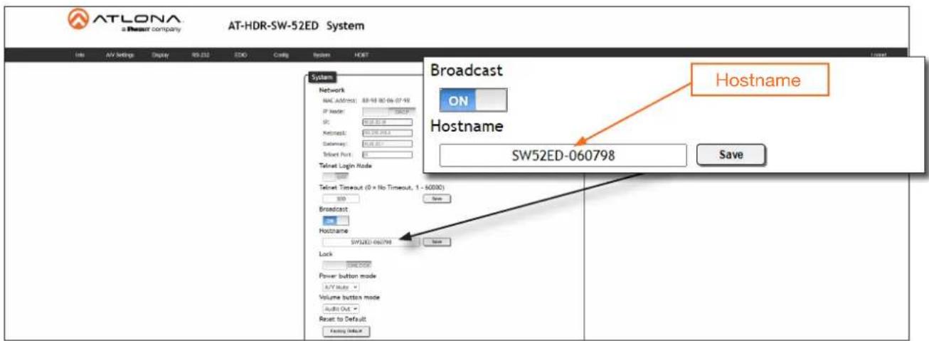
Setting the Host Name
By default, the AT-HDR-SW-52ED is assigned a hostname, which is constructed as follows:
SW52ED-[last six digits of MAC address]
For example, a default hostname might look like this: SW52ED-074431. This value can be changed to easily identify the AT-HDR-SW-52ED within Velocity Device Manager or on a network. The hostname cannot exceed 15 characters in length.
- Log in to the web server.
- Click System in the menu bar.
- Click the Hostname field and enter the desired name.
- Click Save to commit changes.
Locking / Unlocking the Front Panel
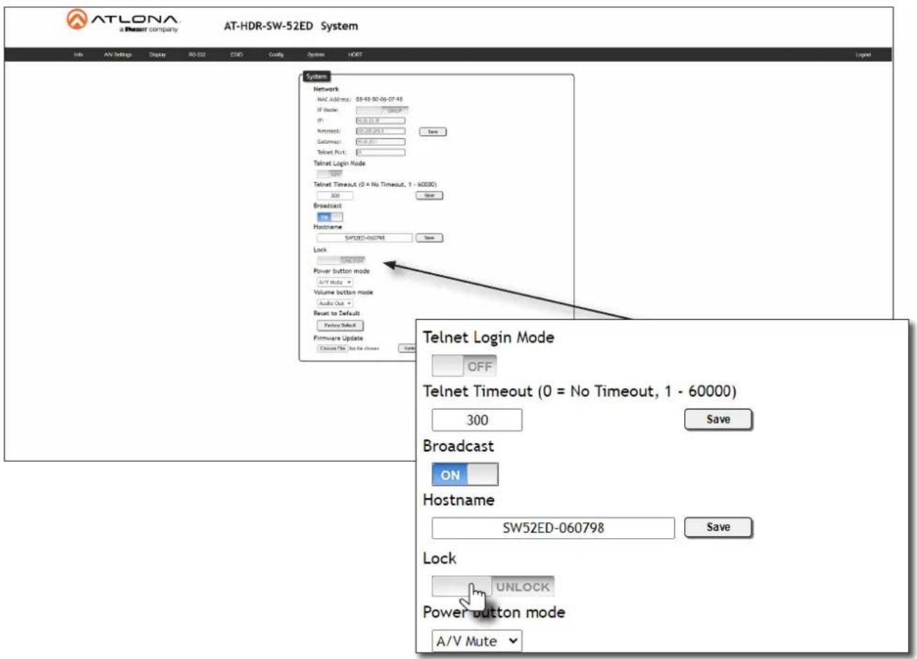
To prevent accidental pressing of the front panel buttons, the front panel buttons can be locked. This may be desirable if, for example, the AT-HDR-SW-52ED is installed in a rack environment. By default, the front panel buttons are unlocked.
- Log in to the web server.
-
Click System in the menu bar.
-
Click the Lock toggle switch to toggle between values. When set to LOCK, all buttons on the front panel will remain disabled until the toggle switch is set to UNLOCK.
Resetting to Factory Defaults
Using the Web Server
The following procedure will reset the AT-HDR-SW-52ED to factory-default settings. The network IP mode will be set to DHCP mode.
- Log in to the web server.
- Click System in the menu bar.
- Click the Factory Default button.
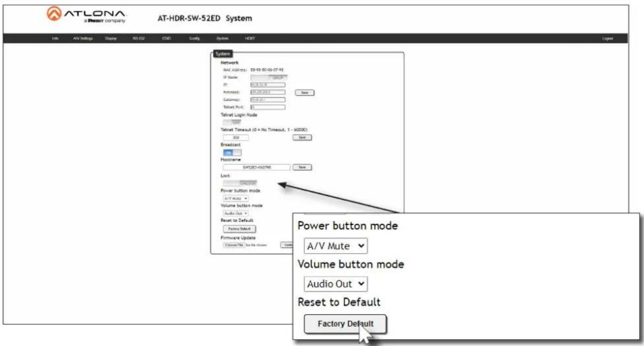
- The following message will be displayed at the top of the screen. Click OK to continue with the factory-default reset procedure. Click Cancel to abort the process.

- Once the factory-default process is complete, the web server Login screen will be displayed.
Device Operation
Using the Front Panel
- Press and hold both the POWER and INPUT buttons for 15 seconds.
- Release both POWER and INPUT buttons once the front panel LED indicators turn on. After two seconds, the front panel LED indicators will turn off.
Configuration and Management Interfaces
Web Server
The AT-HDR-SW-52ED includes a built-in web server. Atlona recommends that the web server be used to set up the AT-HDR-SW-52ED, as it provides intuitive management of all features. Refer to Logging in after Registration (page 17) for more information.
The AT-HDR-SW-52ED is shipped with DHCP enabled. Once connected to a network, the DHCP server will automatically assign an IP address to the unit. Use an IP scanner to determine the IP address of the AT-HDR-SW-52ED. If a DHCP server cannot be located within 15 seconds, the AT-HDR-SW-52ED will be placed in Automatic Private IP Addressing (APIPA) Mode (page 14). If a static IP address is desired, refer to IP Configuration (page 12).
Register page
This page is displayed when the AT-HDR-SW-52ED web server is launched for the first time.
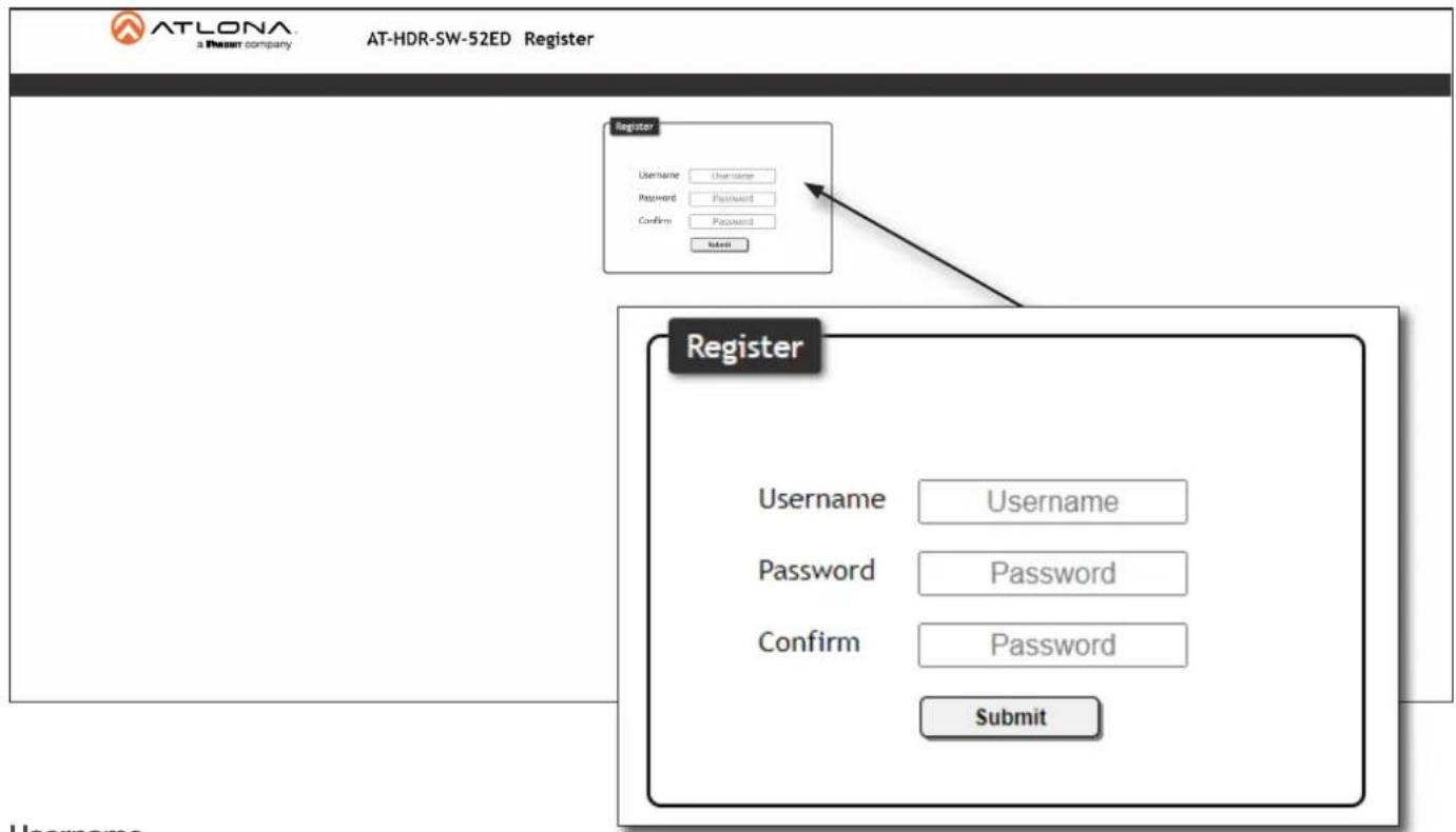
Username
Enter the desired username in this field.
Password
Enter the desired password in this field.
Confirm
Re-enter the desired password in this field.
Submit
Click this button to register the username and password with the AT-HDR-SW-52ED.
Configuration and Management Interfaces
Login page
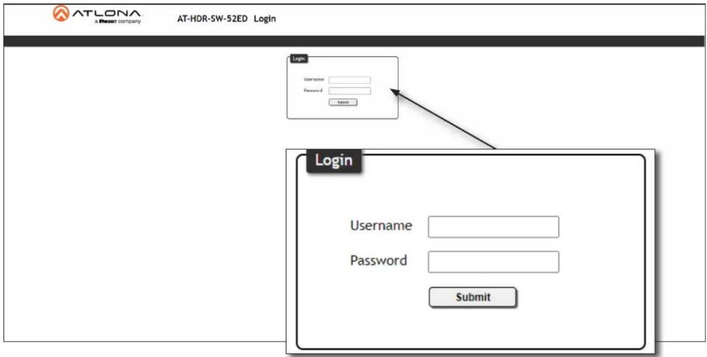
Username
Enter the username in this field.
Password
Enter the password in this field.
Submit
Click this button to log in.
Configuration and Management Interfaces
Info page
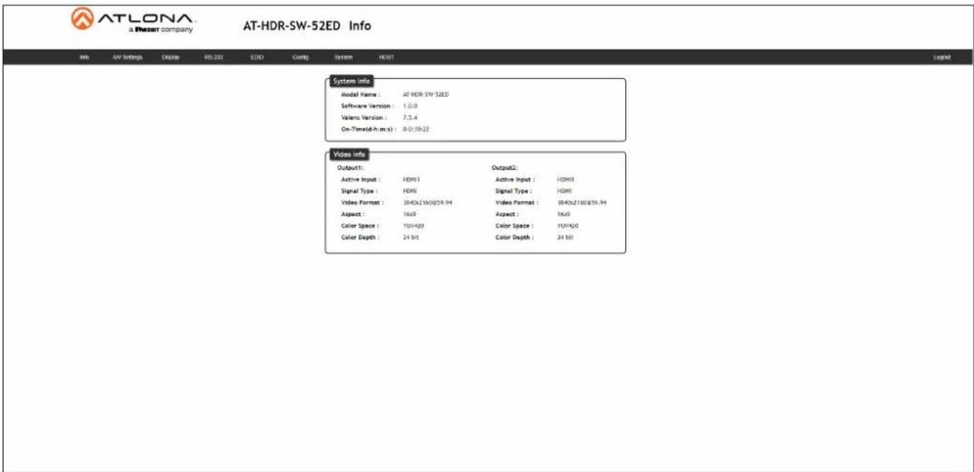
System Info
Model Name
The model SKU of this product.
Software Version
The version of firmware that the AT-HDR-SW-52ED is running. Always make sure to check the AT-HDR-SW-52ED product page, on the Atlona web site, for the latest version of firmware.
Valens Version
The version of Valens firmware for the HDBaseT chip.
On-Time (d-h:m:s)
Displays the amount of time elapsed since the unit was powered.
Video Info
Displays signal information for both the HDMI output (Output 1) and HDBaseT output (Output 2).
Active Input
The input signal port name.
Signal Type
The type of input signal.
Video Format
The input resolution of the source device.
Aspect
Aspect ratio of the input signal.
Color Space
Displays the color space and chroma sub-sampling of the input signal.
Color Depth
The color depth of the input signal.
Configuration and Management Interfaces
A/V Settings page
The A/V Settings page is divided into three sections: Video, Audio, and HDCP. The Video section provides controls for switching modes and input selection. The Audio section provides options to control the output audio volume and de-embedding. The HDCP section controls whether or not HDCP content is allowed to pass.
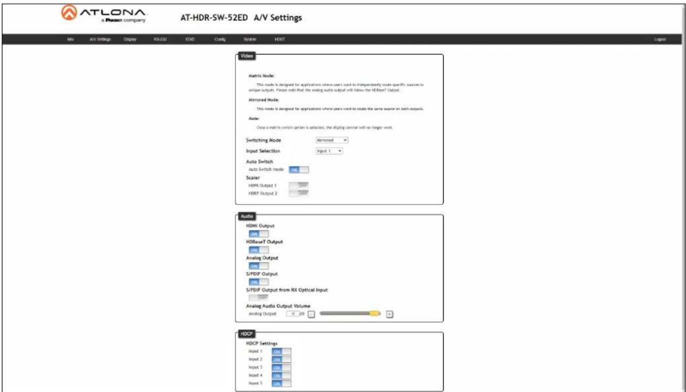
Video
Switching Mode
Click this drop-down list to manually select the switching mode. Refer to Switching Modes (page 18) for more information.
| Setting Description | |
| Mirrored | This is the default switching mode. Once video is detected on any of the input ports, the output signal will be displayed on both HDMI OUT and HDBaseT OUT ports. |
| Matrix Mode | This mode allows the AT-HDR-SW-52ED to independently switch between any input to any output. |
Input Selection
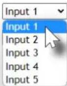
Click this drop-down list to manually select the desired input.
| Setting Description | |||
| Input 1 | Sets HDMI IN 1 as the active input. | ||
| Input 2 | Sets HDMI IN 2 as the active input. | ||
| Input 3 | Sets HDMI IN 3 as the active input. | ||
| Input 4 | Sets HDMI IN 4 as the active input. | ||
| Input 5 | Sets HDMI IN 5 as the active input. | ||
Configuration and Management Interfaces
Auto Switch
Click this toggle switch to enable or disable Auto Switching. When enabled, the AT-HDR-SW-52ED will automatically switch to the another input, if the signal is disrupted on the currently active input.

NOTE: Auto Switching is only available when the Switching Mode is set to Mirrored.
Scaler
Click these toggle switches to enable or disable the scaler pass-through feature for the HDMI outputs. When set to the ON position, 4K content will be down-scaled to 1080p. When set to the OFF position, the output resolution / timing will be the same as the input source. The default setting is OFF.
Audio
HDMI Output
Set this toggle to the OFF position to mute the audio on the HDMI OUT port.
HDBaseT Output
Set this toggle to the OFF position to mute the audio on the HDBaseT OUT port.
Analog Output
Click this toggle switch enable or disable audio output on the L/R port.
S/PDIF Output
Click this toggle switch enable or disable audio output on the S/PDIF OUT port.
S/PDIF Output from RX Optical Input
Click this toggle switch enable or disable audio output on the S/PDIF OUT, received from the optical input on the receiver.
Analog Audio Output Volume
Click and drag this slider to adjust the audio volume on the L/R port.
HDCP
Each input provides control of how HDCP content is handled. Some source devices will send HDCP content if an HDCP-compliant display (sink) is detected. However, there may be applications where sending HDCP content is not desired. Setting the port to the OFF position, will instruct the source to send non-HDCP content to the display. Note that not all sources have this capability. When set to ON, the source will have the ability to transmit HDCP content to the AT-HDR-SW-52ED.

NOTE: Setting this feature to OFF, for any source, does not provide decryption of HDCP content to non-HDCP compliant sink devices. Sources such as Mac® computers and the Sony PlayStation® will always transmit HDCP content.
Configuration and Management Interfaces
Display page
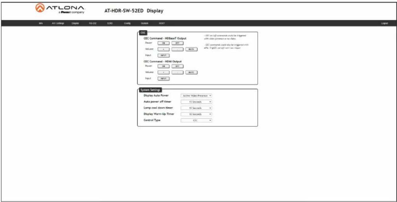
CEC
CEC Command - HDBaseT Output / HDMI Output
Power: Click the ON button to send the power-on command to the display device. Click the OFF button to toggle the power state to off.
Volume: Click the + and - buttons to adjust the volume. Click the MUTE button to test the volume muting function.
Input: Click the INPUT button to cycle between each input.
Consumer Electronics Control (CEC): Atlona has confirmed proper CEC functionality with several current models of Samsung, Panasonic, and Sony displays. However, it is not guaranteed that CEC will work with all displays. Many manufacturers do not support the CEC "off" command, and older displays use proprietary commands. Atlona only supports displays that use the CEC command structure defined in HDMI 1.2a. It is recommended that dealers request an evaluation product from Atlona, before designing a system using the CEC protocol. If this is not possible, then other control methods will need to be considered, in order to control displays using Atlona products.
System Settings
Display Auto Power On
Select Active Video Presence from this drop-down list to allow the AT-HDR-SW-52ED to send the power-on command to the display when an A/V signal is detected. When the AV signal is no longer present, the AT-HDR-SW-52ED will send the power-off command to the display. If this feature is not desired, then set to Disabled. The default settings is Active Video Presence.
Auto power off timer
Click this drop-down list to set the time interval before the command to power-off the display is sent, when an A/V signal is no longer present. The default value is 15 Seconds.
Lamp cool down timer
Click this drop-down list to set the projector lamp cool-down timer, in seconds. This value specifies the time interval that must elapse, after the display control "off" command is sent, before the display "power on" command can be sent. This feature is used to prevent the projector from missing a "power on" command while the lamps are cooling. The default setting is 10 Seconds.
Configuration and Management Interfaces
Display Warm-Up Timer
Click this drop-down list to set the projector lamp warm-up timer, in seconds. During the warm-up interval, the AT-HDR-SW52ED will not start the auto power-off timer. This value specifies the time interval that must elapse, after the display control "on" command is sent, before the display "power off" command can be sent. This feature is used to prevent a "power off" command from being sent while the lamps are warming up. The default setting is 10 Seconds.
Control Type
Click this drop-down list to set the control protocol for the connected display. Click this drop-down to select the control type. Available settings are RS-232, IP, and CEC. The default setting is CEC. If IP or RS-232 are selected, then more fields will be displayed.
If the Control Type is set to RS-232, then the following fields will be available.
![ATLONA a Power company AT-HDR-SW-52ED Display Info AV Settings Display H8-032 EVO Config System HOST Layout CEC CEC Command - HDBaseT Output Power ON OFF Volume → WRITE Input INSERT CEC Command - HDMI Output Power ON OFF Volume → WRITE Input INSERT CEC on/off commands could be triggered with video presence or no video. CEC commands could also be triggered with AFs. TopEC on/off/mid/low/Input System Settings Display Auto Power Active Video Presence Auto power off timer 15 Seconds Lamp cool down timer 10 Seconds Display Warm-Up Timer 10 Seconds Control Type X5-232 RS-331/IP commands Manufacturer Generic Products Generic Model Generic Display Commands [Please use V as a delimiter (or HEX values)] [Using a command, I will cause the transmission to power for 5 seconds between commands. Multiple commands are acceptable to trigger the amount of time.] Repeat Command Status SWARLOD Times 2 ON Per 1 OFF Per 0 Volume+ VOL+ Volume- VOL- Auto WRITE Auto on WRITE ON Auto off WRITE OFF Next Reset](/content/2026/05/1015092/images/e38a5fb7514885b750756d780781249f96971d12a00e91e1e5815cc97311fb7b.jpg)
RS-232/IP commands
Manufacturer
Click this drop-down list to select the manufacturer of the sink device. If the product manufacturer for the device is not listed, select Generic.
| Generic Eiki Optoma SharpAcer Epson Panasonic SonyBarco Hitachi Pjlink ToshibaBenq Infocus Planar ViewsonicCanon Lg Qomo VivtekCasio Nec | Samsung |
Configuration and Management Interfaces
Products
Click this drop-down list to select the product, based on the value set in the Manufacturer drop-down list.
Model
Click this drop-down list to select the model, based on the value set in the Products drop-down list.
Repeat Command > Status
Click this toggle switch to enable or disable the repeat command feature. Some devices may require that the command be sent multiple times before an acknowledge message is received from the display. Refer to the User Manual for the display device for more information. The default setting is ENABLED.
Repeat Command > Times
If the Status toggle switch is set to ENABLED, then this drop-down list will be available. Click this drop-down list to select the number of times to send the command. Available values are 2, 3, and 4.
ON/OFF/Volume+/Volume-/Mute/Mute on/Mute off
These fields are used to enter the required commands for each operation, if the Manufacturer drop-down list is set to Generic. Both Hexadecimal and ASCII formats are permitted. If a manufacturer, product, and model is selected from the above drop-down lists, then these fields will be filled in, automatically, based on the product that was selected.
Send
Click these buttons to send the command string to the device.
Save
Click this button to commit changes.
Revert
Click this button to reset all fields and set the Manufacturer drop-down list to Generic.
Configuration and Management Interfaces
If the Control Type is set to IP, then the following fields will be available.
![ATLONA a Power company AT-HDR-SW-52ED Display Info AV Settings Display RD-032 EHD Config System HEXT Logpad CEC CEC Command - HDBaseT Output Power ON OFF Volume → WRITE Input FREE CEC Command - HDMI Output Power ON OFF Volume → WRITE Input FREE CEC as/off commands could be triggered with state presence or so idle. CEC commands could also be triggered with after. LogCE as/off command input System Settings Display Auto Power Active Video Presence Auto power off timer 15 Seconds Lamp cool down timer 10 Seconds Display Warm-Up Timer 10 Seconds Control Type IP TCP/IP Settings of Controlled Device IP Mode Non Login IP Address HU: 168.1.1 Port 21 Save RS-132/IP commands Manufacturer Generic Products Generic Model Generic Display Commands [Please use is as a delimiter for HEX values] [Using a comma,] will cause the transmission to pause for 5 seconds between commands. Multiple commands are acceptable to increase the amount of time.] Repeat Command Status: HUH-735 Times: 2 ON PW 1 OFF PW 0 Volume+ VOL+ Volume- VOL+ Mute WUTE Mute on WUTE OH Mute off WUTE OFF Save Reset](/content/2026/05/1015092/images/b2b2b6bbc03cda22a93bd186ff51821818d0d6d410a4ab471a1d08822cf414fa.jpg)
TCP/IP Settings of Controlled Device
IP Mode
Click this drop-down list to select Login or Non-Login. When set to Non-Login, the login credential fields (Username and Password) will be hidden. The default setting is Non-Login.
IP Address
Enter the IP address of the device in this field.
Port
Enter the port number for the device in this field.
Username
This field is only available if the IP Mode is set to Login. Enter the username in this field.
Password
This field is only available if the IP Mode is set to Login. Enter the password in this field.
Configuration and Management Interfaces
RS-232/IP commands
Manufacturer
Click this drop-down list to select the manufacturer of the sink device. If the product manufacturer for the device is not listed, select Generic.
| Generic Eiki Optoma SharpAcer Epson Panasonic SonyBarco Hitachi Pjlink ToshibaBenq Infocus Planar ViewsonicCanon Lg Qomo VivtekCasio Nec | Samsung |
Products
Click this drop-down list to select the product, based on the value set in the Manufacturer drop-down list.
Model
Click this drop-down list to select the model, based on the value set in the Products drop-down list.
Repeat Command > Status
Click this toggle switch to enable or disable the repeat command feature. Some devices may require that the command be sent multiple times before an acknowledge message is received from the display. Refer to the User Manual for the display device for more information. The default setting is ENABLED.
Repeat Command > Times
If the Status toggle switch is set to ENABLED, then this drop-down list will be available. Click this drop-down list to select the number of times to send the command. Available values are 2, 3, and 4.
ON/OFF/Volume+/Volume-/Mute/Mute on/Mute off
These fields are used to enter the required commands for each operation, if the Manufacturer drop-down list is set to Generic. Both Hexadecimal and ASCII formats are permitted. If a manufacturer, product, and model is selected from the above drop-down lists, then these fields will be filled in, automatically, based on the product that was selected.
Send
Click these buttons to send the command string to the device.
Save
Click this button to commit changes.
Revert
Click this button to reset all fields and set the Manufacturer drop-down list to Generic.
Configuration and Management Interfaces
RS-232 page
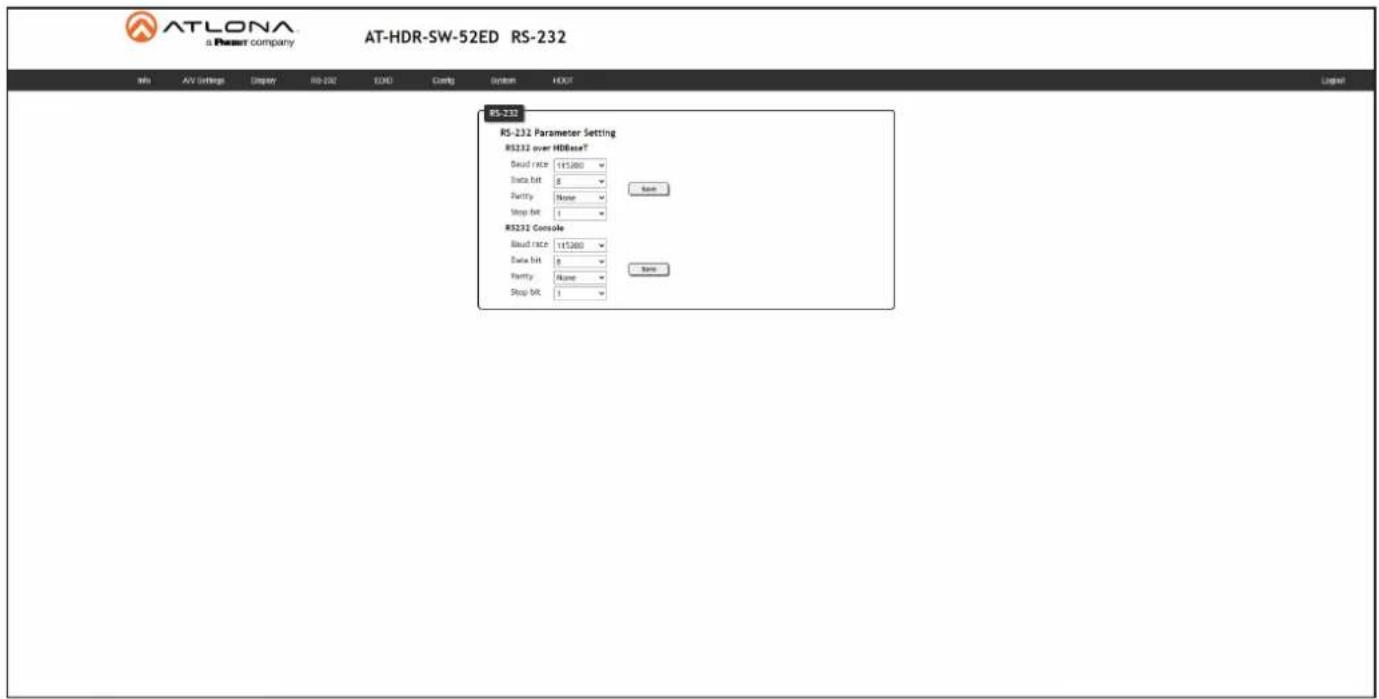
RS-232
RS-232 Parameter Setting
RS-232 settings for local or HDBaseT RS-232 control.
• RS232 over HDBaseT
Sets the RS-232 port settings when controlling a display, over HDBaseT, using a control system. Refer to RS-232 Control (page 30) for more information.
- RS232 Console
Sets the RS-232 port settings used for local control by a third-party control system.
- Save
Click this button to commit all changes.
| Setting Description | |
| Baud rate Sets the baud rate | The following options are available: 2400, 4800, 9600, 19200, 38400, 56000, 57600, 115200. |
| Data bit Sets the number of | data bits used to represent each character of data. The following options are available: 7 or 8. |
| Parity Sets the parity bit, which can be included with each character to detect errors during the transmission of data. The following options are available: None, Odd, or Even. | |
| Stop bit Sets the stop bit. | Stop bits are sent at the end of each character, allowing the client to detect the end of a character stream. The following options are available: 1 or 2. |
Configuration and Management Interfaces
EDID page
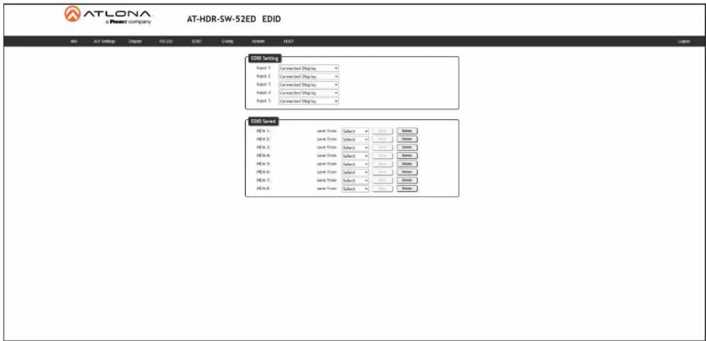
EDID Settings
Click these drop-down lists to select the desired EDID to be used for each input. The following EDID presets are available. When selecting an EDID, make sure that the display/sink device is capable of supporting the resolution/timing. If the sink device is not able to support a feature, then the source will not be displayed. Selecting the Connected Display EDID will provide the most compatible settings for most displays. In addition, eight memory locations are available for storing captured EDID data. If an EDID is stored in a memory location, it will also be added to the list available EDID selections.
| EDID Description | |
| Connected Display Uses the downstream | EDID of the connected display |
| ATL 4K60 MCH 3840 x 2160 (UHD) with multichannel audio support | |
| ATL 4K60 PCM MCH 3840 x 2160 (UHD) with PCM multichannel audio support | |
| ATL 1080P MCH 1920 x 1080p with multichannel audio support | |
| ATL 1080P 2CH 1920 x 1080p with two-channel audio support | |
| ATL 1080P DD 1920 x 1080p with Dolby | TM Digital audio support |
| ATL 1080P DVI 1920 x 1080p for DVI displays | |
| ATL 720P DD 1280 x 720p with Dolby | TM Digital audio support |
| ATL 720P 2CH 1280 x 720p with two-channel audio support | |
EDID Saved
The AT-HDR-SW-52ED provides eight memory locations used for storing captured EDID data. Click these drop-down lists to select the desired output and press Save to store the EDID. Press the Delete button to erase the EDID data. Refer to EDID Management (page 44) for more information.
Configuration and Management Interfaces
Config page

Configuration
Old Username
Enter the current username in this field.
Old Password
Enter the current password in this field.
New Username
Enter the new username in this field.
New Password
Enter the new password in this field.
Confirm New Password
Verify the new password by retyping it in this field.
Save
Click this button to apply all changes.
Configuration and Management Interfaces
System page
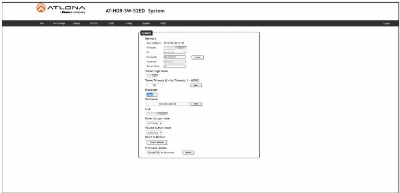
System
MAC address
Displays the MAC address of the AT-HDR-SW-52ED.
IP Mode
Click this toggle to set the IP mode of the AT-HDR-SW-52ED.
| Setting Description | |
| DHCP | Uses an available DHCP server to assign an IP address. |
| STATIC IP | Allows the IP address, subnet mask, and gateway IP address to be entered manually. |
IP
Enter the IP address of the AT-HDR-SW-52ED in this field. This field will only be available if IP Mode is set to STATIC IP.
Netmask
Enter the subnet mask in this field. This field will only be available if IP Mode is set to STATIC IP.
Gateway
Enter the gateway (router) address in this field. This field will only be available if IP Mode is set to STATIC IP.
Telnet Port
Enter the Telnet listening port in this field.
Telnet Login Mode
Click this toggle to set the login mode to either ON or OFF. If this feature is set to ON, then use the same login credentials as the web server.
| Setting Description | |
| ON | The AT-HDR-SW-52ED will prompt for both the username and password at the start of a Telnet session. |
| OFF | No username and password is required for Telnet sessions. |
Configuration and Management Interfaces
Telnet Timeout
Sets the Telnet timeout interval, after no activity, in seconds. Acceptable integer values are: 0 - 60000. The default setting is 300. Once the interval has expired, the Telnet session will be closed. If this field is set to 0, then the timeout interval is infinite. Click the Save button to commit changes.
Broadcast
This option determines whether or not systems changes are announced over TCP/IP connections to any listening devices.
| Setting Description | |
| ON | System changes will be announced over TCP/IP connections to any device that has a TCP/IP connection to the AT-HDR-SW-52ED. This is the default setting. |
| OFF | Only the device that is sending the commands will receive feedback from the commands or any system changes. Read queries, such as the IPCFG and Type commands, are not announced and will only return information to the requester. |
Hostname
Displays the hostname of the AT-HDR-SW-52ED, as it would appear on a network. To change the hostname, type the new hostname in this field and click the Save button. Refer to Setting the Host Name (page 53) for more information.
Lock
Click to lock or unlock the buttons on the front panel. Locking the front panel buttons is useful in preventing accidental button activation within rack environments.
| Setting Description | |
| LOCK | Locks the front panel buttons. |
| UNLOCK | Unlocks the front panel button, allowing them to be functional. |
Power button mode
Click this drop-down list to select the desired function of the power button. Refer to Display Control (page 34) for more information.
| Setting Description | |
| A/V Mute | Toggles the AT-HDR-SW-52ED between standby mode and normal operating mode. This is the default setting. |
| CEC | When a sink device (display) is connected to the AT-HDR-SW-52ED, pressing the POWER button will toggle the power state of the display using the CEC protocol. The power state of the AT-HDR-SW-52ED is unaffected. Power-on and power-off commands are sent over both the HDBaseT OUT and HDMI OUT ports. |
| RS-232 | POWER button will send RS-232 commands over HDBaseT to compatible receivers and displays. |
| IP | POWER button will send the commands over Ethernet using either the LAN port. |
Configuration and Management Interfaces
Volume button mode
Click this drop-down list to select the desired function of the volume up/down buttons. Refer to Display Control (page 34) for more information.
| Setting Description | |
| Audio Out | VOLUME buttons control the output volume on the AT-HDR-SW-52ED. This is the default setting. |
| CEC | When a sink device (display) is connected to the AT-HDR-SW-52ED, pressing the VOLUME buttons will adjust the volume of the display using the CEC protocol.The output volume of the AUDIO ports on the AT-HDR-SW-52ED is unaffected. Volume commands are sent over both the HDBaseT OUT and HDMI OUT ports. |
| RS-232 | VOLUME buttons will send RS-232 commands over HDBaseT to compatible receivers and displays. |
| IP | VOLUME buttons will send the commands over Ethernet using either the LAN port. |
Reset to Default
Click the Factory Default button to set the AT-HDR-SW-52ED to factory-default settings.
Firmware Update
Click the Choose File button to select the firmware file, when upgrading the firmware on the AT-HDR-SW-52ED. Once the firmware file is selected, click the Update button. Refer to Updating the Firmware (page 74) for more information.
Configuration and Management Interfaces
HDBT page
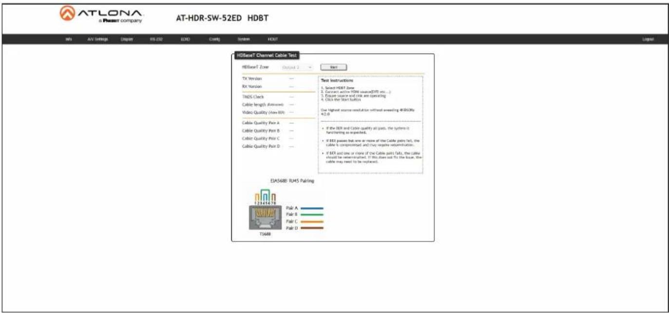
HDBaseT Channel Cable Test
HDBaseT Zone
There is only one zone. The value in the drop-down list cannot be changed.
Start
Click the Start button to begin the HDBaseT testing process. During testing, the button text will change to Stop. Click the Stop button to halt the HDBaseT testing process. HDBaseT testing can be performed at any time, while the unit is powered. Refer to the instructions on this web page for information on how to interpret the Bit Error Rate (BER) and cable test results.
TX Version
The version of the Valens chip on the transmitter.
RX Version
The version of the Valens chip on the receiver.
TMDS Clock
Displays the pixel clock speed. If no source is connected, then this field will display as None.
Cable length (Estimated)
This field indicates the approximate length of the category cable connected between the HDBaseT port on the AT-HDR-SW-52ED and the receiver. If the cable length is less than 15 feet, then this value will be displayed as 0 (zero).
Video Quality (Video BER)
The Bit Error Rate (BER). This field displays either PASS or FAIL during a test.
Cable Quality Pair (A, B, C, D)
Each of these fields will display either PASS or FAIL during a test.
Appendix
Updating the Firmware
Updating the firmware can be completed using either the USB interface or the web server. Atlona recommends using the web server for updating the MCU firmware. However, if a network connection is not available, the AT-HDR-SW-52ED firmware can be updated using a USB-A to mini-USB cable. USB update is not supported under macOS®.
Using the Web Server
Requirements:
- AT-HDR-SW-52ED
- Firmware file
-
Computer
-
Connect an Ethernet cable from the computer, containing the firmware, to the same network where the AT-HDR-SW-52ED is connected.
- Log in to the web server and go to the System page (page 70).
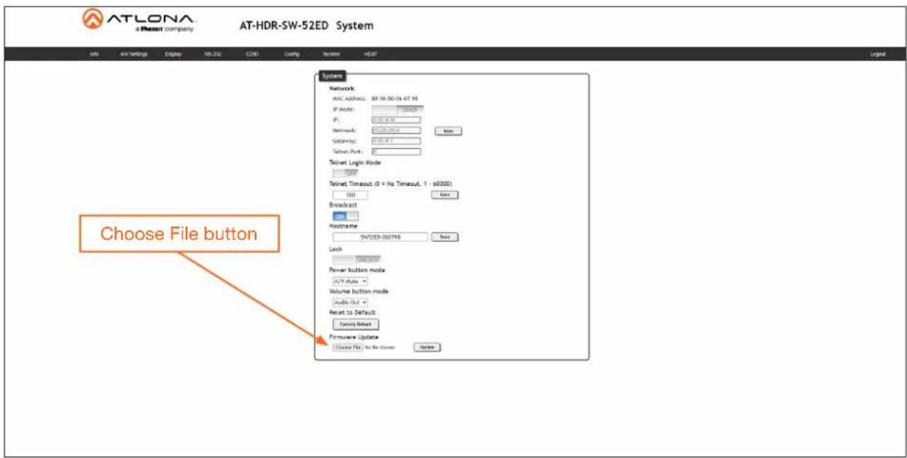
- Click the Choose File button, under Firmware Update.
- Browse to the location of the firmware file, select it, and click the Open button.
- Click the Update button to begin the update process. The following message box will be displayed.
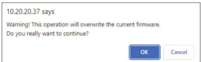
-
Click the OK button to begin the firmware update process. Click the Cancel button to cancel the process.
-
After the firmware update process is complete, the Login screen will be displayed, indicating that the update process is complete.
Appendix
Using USB
Required items:
- AT-HDR-SW-52ED
• Computer containing the firmware file.
• USB-A to mini-USB cable

NOTE: USB update is not supported on macOS®.
- Disconnect power from the AT-HDR-SW-52ED.
- Connect the USB-A to mini-USB cable between the computer and the FW port on the AT-HDR-SW-52ED.
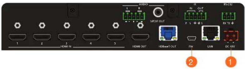
-
Press and hold down the INPUT button on the front panel, while connecting the power supply to the AT-HDR-SW-52ED. Once the power supply has been connected, release the INPUT button.
-
The POWER button will begin flashing slowly, indicating that the AT-HDR-SW-52ED is in Update Mode.
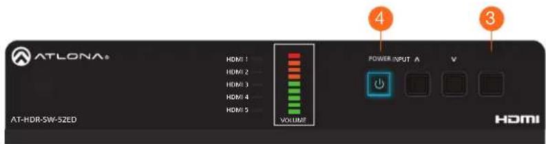
- A virtual USB drive will be displayed in a pop-up window on the computer. Drag-and-drop the firmware file to the virtual drive. During the firmware update procedure, the POWER button will flash more rapidly.
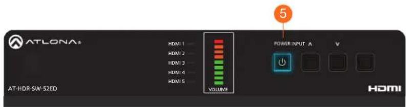
-
After the file has been copied, disconnect the USB cable from both the computer and the AT-HDR-SW-52ED.
-
The firmware update process is complete.
Appendix
Mounting Instructions
The AT-HDR-SW-52ED includes two mounting brackets, which can be used to attach the unit to any flat surface. Use the two enclosure screws, on the sides of the unit to attach the mounting brackets.
Single Unit Rack Installation
- Attach the included small rack ear to one side of the AT-HDR-SW-52ED, using the included screws.
- Attach the included longer rack ear to the opposite side of the AT-HDR-SW-52ED using the included screws.
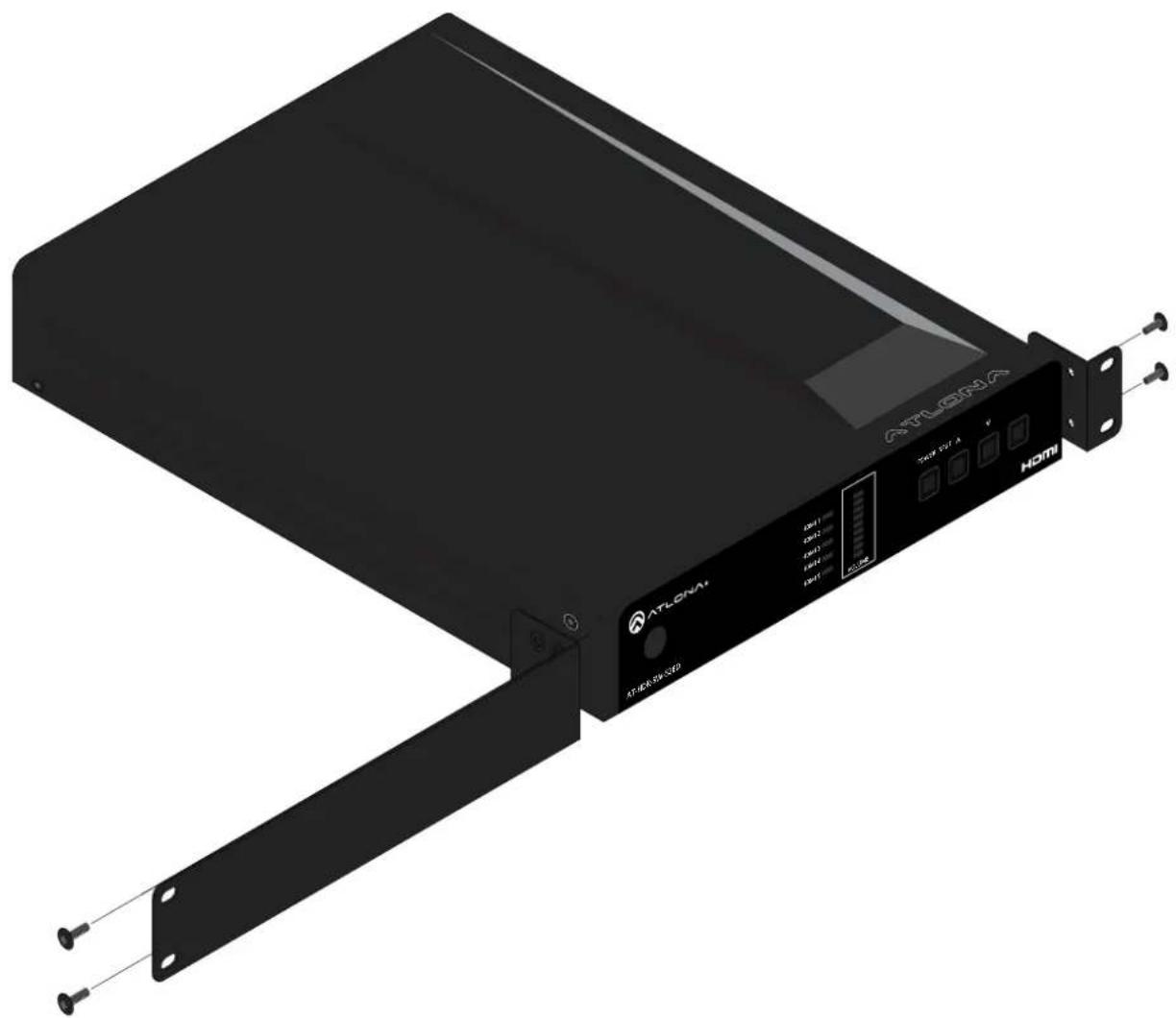
natural_image
Exterior view of a black ATLONA network device with attached hardware bracket (no readable text or symbols)Appendix
Dual Unit Rack Installation
- Turn both units upside-down on a flat surface, next to each other, as shown.
- Position the included mounting plate over the pre-drilled holes on the bottom of the enclosure. When attaching the mounting plate, the countersink bevels on the mounting plate should face upward.
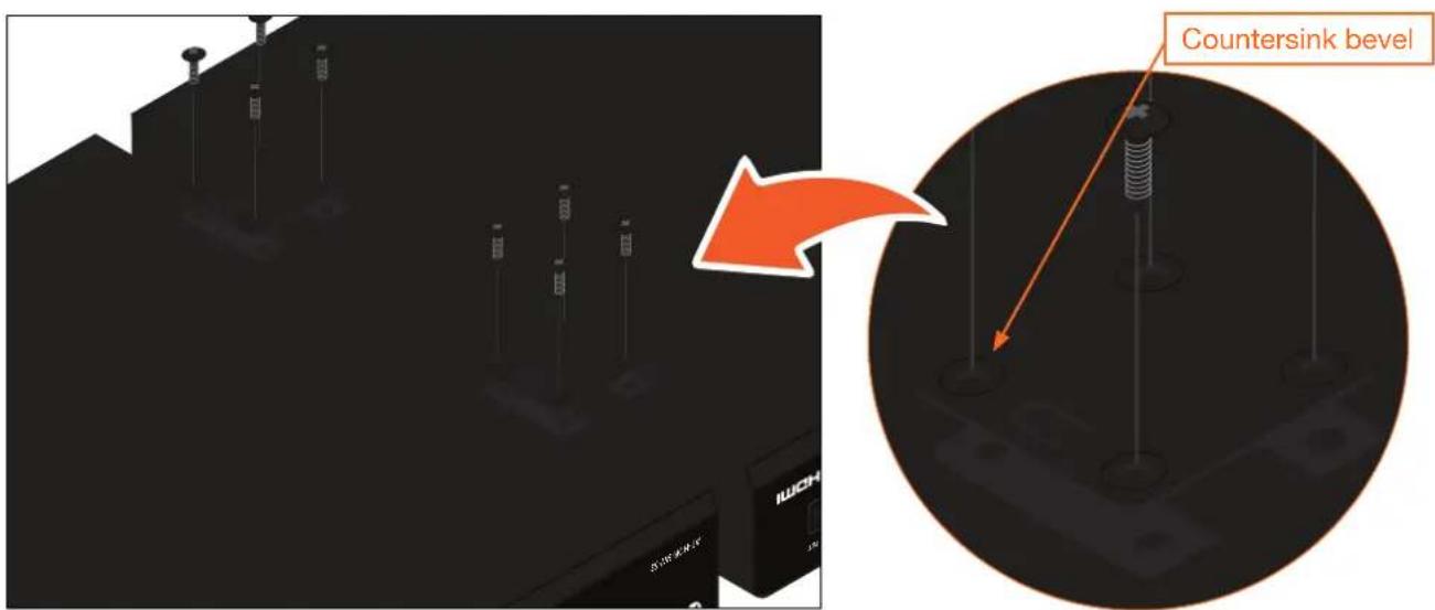
- Turn the attached units over and install the rack ears (sold separately) to one side of each enclosure using the included screws.
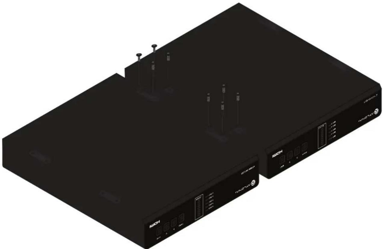
natural_image
Exterior view of two black HAC devices with ports and indicator lights (no readable text or symbols)Appendix
Flat Surface
-
Turn the unit upside down, on a flat surface.
-
Position the included mounting plates over the pre-drilled holes on the bottom of the enclosure. When attaching mounting plates, the countersink bevels on the mounting plates should face upward.
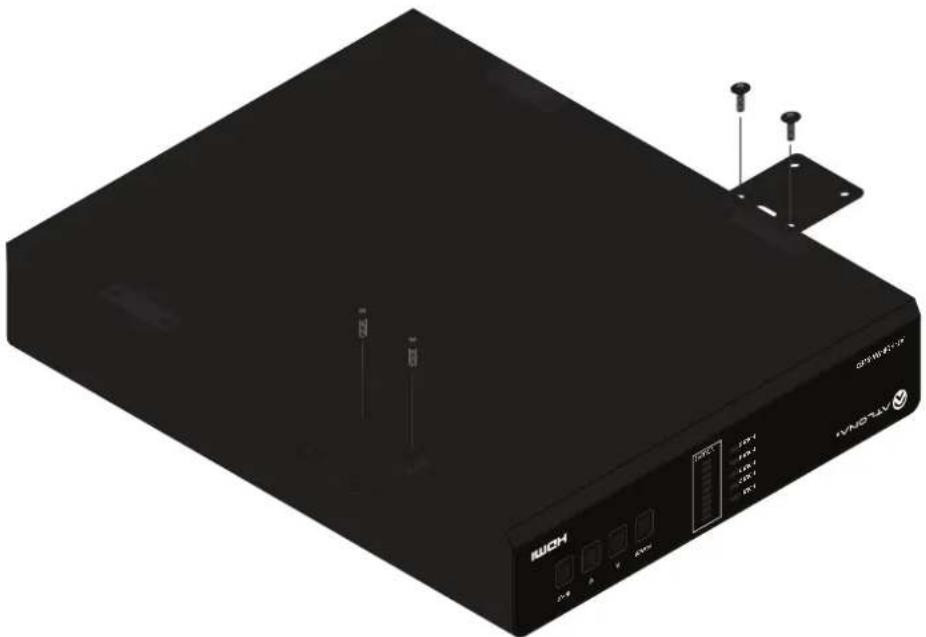
natural_image
Black industrial electronic device with labeled ports and connectors (no readable text or symbols beyond branding)- Mount the unit using the circular holes, on each mounting plate. If using a drywall surface, a #6 drywall screw is recommended. Mounting screws are not included.
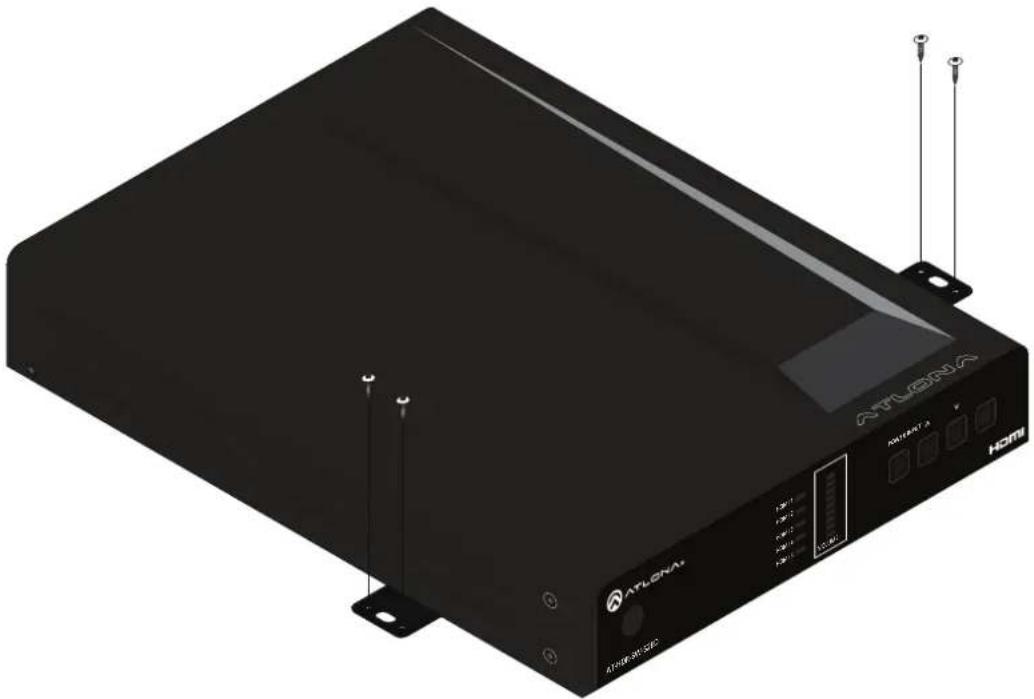
natural_image
Exterior view of a black ATLGENA HOMI device with visible ports and connectors (no text or symbols on the device body)
NOTE: The unit can also be mounted under a flat surface, such as a table, by turning the unit upside down.
Specifications
| Video | ||
| Signal Input - HDMI | Output - HDMI, HDBaseT | |
| Copy Protection HDCP 2.2 | ||
| Pixel Clock 600 MHz | ||
| UHD/HD/SD 4096x2160 (DCI) @ 24/25/30/50/60 Hz | 720x576p @ 50 Hz | |
| 3840x2160 (UHD) @ 24/25/30/50/60 Hz | 720x576i @ 25/50 Hz | |
| 1920x1080p @ | 720x480p @ 60 Hz | |
| 23.97/24/25/29.97/30/50/60 Hz | 640x480p @ 60 Hz | |
| 1920x1080i @ 50/60 Hz | 640x480i @ 60 Hz | |
| 1280x720p @ 30/50/60 Hz | ||
| VESA | 2560x2048 | 1366x768 |
| All resolutions are 60 Hz | 2560x1600 | 1360x768 |
| 2048x1536 | 1280x1024 | |
| 1920x1200 | 1280x800 | |
| 1680x1050 | 1280x768 | |
| 1600x1200 | 1152x768 | |
| 1600x900 | 1024x768 | |
| 1440x900 | 800x600 | |
| 1400x1050 | 640x480 | |
| Color Space YUV, RGB | ||
| Chroma Subsampling 4:4:4, 4:2:2, 4:2:0 | ||
| Color Depth 8-bit, 10-bit, 12-bit | ||
| HDR HDR10, Hybrid-Log Gamma (HLG), and Dolby® VisionTM @ 60 Hz | ||
| Audio | |||
| HDMI Pass-Through Formats L | PCM 2.0LPCM 5.1LPCM 7.1 | Dolby®DigitalDolby Digital PlusTMDolby TrueHDDolby Atmos® | DTS®Digital SurroundTMDTS-HD Master AudioTMDTS:X® |
| S/PDIF LPCM 2.0 Dolby | ®Digital DTS | ®Digital SurroundTM | |
| Bit Depth Up to 24 bits | |||
| Analog Audio | |||
| Format | Stereo 2-Channel | ||
| Balanced Output | +4 dBu nominal gain, +19 dB headroom | ||
| Frequency Response | 20 Hz to 20 kHz, ± 0.5 dB | ||
| THD+N | < 0.006% at 20 Hz to 20 kHz | ||
| SNR | >105 dB at 1 kHz, zero clipping @ 0 dBFS, unweighted | ||
| Sample Rate | 32 kHz, 44.1 kHz, 48 kHz, 88.2 kHz, 96 kHz, 176.4 kHz, 192 kHz | ||
| Ethernet | |
| Port | 1 x RJ45 |
| Standards and Protocols | HTTP, Telnet |
| Speeds | 10/100 Mbps |
| Addressing | DHCP, Static – selectable through built-in web server and Telnet commands |
Appendix
| RS-232 | ||
| Port | 1 x 3-pin captive screw | |
| Use | Unit and external device control and configuration | |
| Baud Rates | 2400, 4800, 9600, 19200, 38400, 57600, 115200 | |
| Data Flow | Bidirectional | |
| IR | ||
| Port | 1 x 5-pin captive screw | |
| Use | Unit and external device control and configuration | |
| Carrier Frequency Range | 30 kHz - 60 kHz | |
| Data Flow | Bidirectional | |
| CEC | |
| Ports | 1 x HDMI OUT, Type A, 19-pin female1 x HDBaseT OUT, RJ45 |
| Triggering | Through HDMI and/or HDBaseT |
| Resolution / Distance | 4K/UHD - Feet / Meters | 1080p - Feet / Meters | ||
| HDMI IN/OUT | 15 | 5 | 30 | 10 |
| CAT5e | 295 | 90 | 330 | 100 |
| CAT6/6a/7 | 330 | 100 | 330 | 100 |
| Buttons and Indicators | |
| Buttons:POWER, UP, DOWN, INPUT | 4 x momentary, tact-type |
| Indicators:POWERHDMI 1 - HDMI 5,VOLUME | 1 x LED, blue5 x LED, blue9 x LED, green, amber, red |
| Connectors | |
| HDMI IN 5 x Type A, 19-pin female | |
| HDMI OUT 1 x Type A, 19-pin female | |
| HDBaseT OUT 1 x RJ45 | |
| LAN 1 x RJ45 | |
| L/R 1 x 5-pin captive screw | |
| S/PDIF OUT 1 x RCA, female | |
| RS-232 1 x 3-pin captive screw | |
| IR IN / OUT 1 x 5-pin captive screw | |
| FW 1 x mini-USB | |
| DC 48V 1 x 2-pin captive screw | |
| Environmental Fahrenheit Celsius | |||
| Operating Temperature +32 to | +122 | 0 to +50 | |
| Storage Temperature | -4 to +140 -20 to +60 | ||
| Operating Humidity (RH) | 20% to 90%, non-condensing | ||
Appendix
| Power | ||
| Consumption 22.4 W | 37.4 W (with PoE) | |
| BTU/h | 76.4 | |
| External Power Supply | 100 - 240 V AC, 50/60 HzOutput: 48 V / 0.83 A DC | |
| Dimensions (H x W x D) Inches Millimeters | ||
| Unit 1.34 x 8.19 x 4.41 34 x 208 x 112 | ||
| Power Supply(AT-PS-48083-C) | 1.42 x 1.81 x 4.41 36 x 46 x 112 | |
| Weight Pounds Kilograms | ||
| Device 1.44 3.15 | ||
| Certification | ||
| Device CE, RoHS, FCC | ||
| Power Supply CE, FCC, UL, CUL, TUV-GS, CB, PSE, CCC | ||
| Compliance | ||
| NDAA-889 Yes | ||
| TAA Yes | ||
| Warranty | ||
| Device To view the product warranty, use the following link:https://atlona.com/warranty | ||
- with HDMI and HDBaseT Outputs
- Version Information
- Sales, Marketing, and Customer Support
- Operating Notes
- Warranty
- Safety and Certification
- CAUTION
- FCC Compliance
- Copyright, Trademark, and Registration
- Table of Contents
- Configuration and Management Interfaces 57
- Appendix
- Introduction
- Features
- Package Contents
- Panel Description
- HDMI 1 - HDMI 5: Input LED Indicators
- VOLUME
- POWER
- Cursor Buttons
- INPUT
- HDMI IN
- L/R
- HDMI OUT
- AUDIO - S/PDIF OUT
- HDBaseT OUT
- FW
- IR IN/OUT
- LAN
- RS-232
- DC 48V
- Installation
- Power
- Connection Instructions
- IP Configuration
- Using the Front Panel
- Using the Web Server
- Network
- Setting the IP Address Using Commands
- - Setting static IP mode
- - Setting DHCP mode
- Automatic Private IP Addressing (APIPA) Mode
- Device Operation
- LED Indicators
- Logging in to the Web Server
- Login Registration
- Logging in after Registration
- Switching Modes
- Mirrored Mode
- Matrix Mode
- Matrix Mode:
- Mirrored Mode:
- Note:
- Switching Mode
- Matrix Mode HDMI Source
- Matrix Mode HDBaseT Source
- Scaler
- Auto Switching
- Enabling / Disabling Auto Switching
- Scaler Pass-Through
- Notes on Scaling
- Audio Management
- HDMI / HDBaseT Audio Muting
- Analog Audio Output
- L/R Port Wiring
- De-Embedding Audio
- S/PDIF Audio Muting
- S/PDIF Audio Muting from RX
- HDCP Content
- HDCP
- HDCP Settings
- RS-232 Control
- Console Mode
- Pass-Through Mode
- IR Control
- Controlling Display Devices
- Controlling Source Devices
- Display Control
- Using CEC
- Input Selection
- System Settings
- CEC
- CEC Command - HDBaseT Output
- CEC Command - HDMI Output
- Optional CEC Front Panel Button Control
- RS-232 Configuration
- Optional RS-232 Front Panel Button Control
- TCP/IP Settings of Controlled Device
- Optional IP Front Panel Button Control
- Completing RS-232 or IP Configuration
- RS-232/IP commands
- Repeat Command
- HEX Command Strings
- ASCII Command Strings
- EDID Management
- Using the Downstream EDID
- EDID Presets
- Storing EDID Data
- User Management
- System Configuration
- Getting the MAC Address
- Changing the Network IP Mode
- Changing the Telnet Port
- Telnet Login Mode
- Telnet Timeout
- Broadcast
- Setting the Host Name
- Locking / Unlocking the Front Panel
- Resetting to Factory Defaults
- Configuration and Management Interfaces
- Web Server
- Register page
- Username
- Password
- Confirm
- Submit
- System Info
- Model Name
- Software Version
- Valens Version
- On-Time (d-h:m:s)
- Video Info
- Active Input
- Signal Type
- Video Format
- Aspect
- Color Space
- Color Depth
- A/V Settings page
- Video
- Auto Switch
- Audio
- HDMI Output
- HDBaseT Output
- Analog Output
- S/PDIF Output
- S/PDIF Output from RX Optical Input
- Analog Audio Output Volume
- Display page
- CEC Command - HDBaseT Output / HDMI Output
- Display Auto Power On
- Auto power off timer
- Lamp cool down timer
- Display Warm-Up Timer
- Control Type
- Manufacturer
- Products
- Model
- Repeat Command > Status
- Repeat Command > Times
- ON/OFF/Volume+/Volume-/Mute/Mute on/Mute off
- Send
- Save
- Revert
- IP Mode
- IP Address
- Port
- RS-232
- RS-232 Parameter Setting
- • RS232 over HDBaseT
- - RS232 Console
- - Save
- EDID Settings
- EDID Saved
- Configuration
- Old Username
- Old Password
- New Username
- New Password
- Confirm New Password
- System
- MAC address
- IP
- Netmask
- Gateway
- Telnet Port
- Hostname
- Lock
- Power button mode
- Volume button mode
- Reset to Default
- Firmware Update
- HDBT page
- HDBaseT Channel Cable Test
- HDBaseT Zone
- Start
- TX Version
- RX Version
- TMDS Clock
- Cable length (Estimated)
- Video Quality (Video BER)
- Cable Quality Pair (A, B, C, D)
- Updating the Firmware
- Using USB
- Mounting Instructions
- Single Unit Rack Installation
- Dual Unit Rack Installation
- Flat Surface
Brand : Atlona
Model : AT-HDR-SW-52ED
Category : Switch