Chroma A - Computer Case Azza - Free user manual and instructions
Find the device manual for free Chroma A Azza in PDF.

User questions about Chroma A Azza
0 question about this device. Answer the ones you know or ask your own.
Ask a new question about this device
Download the instructions for your Computer Case in PDF format for free! Find your manual Chroma A - Azza and take your electronic device back in hand. On this page are published all the documents necessary for the use of your device. Chroma A by Azza.
USER MANUAL Chroma A Azza
natural_image
Line drawing of a rectangular container with a triangular symbol on the top side (no text or labels)USER MANUAL
- Specifications
- Chassis Parts
- Control Panel Functions
- 3.5"/2.5" HDD Installation
- Optional Liquid Cooling System
- AZZA PRISMA Digital RGB Fan Installation For Motherboard
- RF Remote
| Model | |
| Model Name | Chroma 410 |
| Model Number | CSAZ-410A |
| Specifications | |
| Type | ATX Mid Tower |
| Color | Black(exterior)/Black(interior) |
| Side Panel Window | Tempered Glass with rubber mounts |
| Max CPU Cooler Height | Up to 162mm |
| Max Video Card Length | Up to 400mm Long Video Card |
| Power Supply | Not included |
| Motherboard Compatibility | ATX, Micro ATX |
| Expansion | |
| External 5.25" Drive Bays | 0 |
| Internal 2.5" Drive Bays | Up to 6 |
| Internal 3.5" Drive Bays | Up to 2 |
| Expansion Slots | 7(Horizontal)+2(Vertical) |
| Top Ports | 2xUSB3.0, 2xUSB2.0, HD Audio |
| Physical Specifications | |
| Dimensions (HxWxD) | 520x205x500mm / 20.5x8.1x19.7 inches |
| Weight | 6.82 kg / 15.0 lbs |
| Features | |
| Digital RGB Light Effects | Digital RGB light on the front. All digital RGB light devices controlled by RF Remote (included) or motherboard. |
| Tempered Glass Side Window | High-quality tempered glass side windows allow for clear visuals to inner components |
| Available Fan Ports | 2x120mm Fan ports on the top3x120mm or 2x140mm Fan ports in the front(2x120mm Black Fans included)1x120mm Fan port in the rear(1x120mm PRISMA-Digital RGB Fan included) |
| Dust Filters | Dustproof PVC Net x2 on bottom of Chassis |
| Water Cooling | Supports radiators up to 240mm on top / 360mm in front |
| Isolated Chamber | Power supply is housed inside its own isolated chamber, preventing its heat from affecting other components |
| Easy Installation Cooler | A pre-cut hole for easy installation of CPU Cooler, eliminating the need to remove the motherboard |
Digital RGB lighting: Also known as "addressable" RGB. Digital RGB lights offer the ability to assign colors to each LED diode individually, whereas analog RGB lighting only allows the LED strip to display one color along the whole strip at a time. The terms "digital" and "addressable" can be used interchangeably when referring to RGB lighting.
| Model | |
| Model Name Chroma 410 | |
| Model Number CSAZ-410B | |
| Specifications | |
| Type | ATX Mid Tower |
| Color | Black(exterior)/Black(interior) |
| Side Panel Window | Tempered Glass with rubber mounts |
| Max CPU Cooler Height Up to 162mm | |
| Max Video Card Length Up to 400mm Long Video Card | |
| Power Supply Not included | |
| Motherboard Compatibility | ATX, Micro ATX |
| Expansion | |
| External 5.25" Drive Bays | 0 |
| Internal 2.5" Drive Bays | Up to 6 |
| Internal 3.5" Drive Bays | Up to 2 |
| Expansion Slots | 7(Horizontal)+2(Vertical) |
| Top Ports | 2xUSB3.0, 2xUSB2.0, HD Audio |
| Physical Specifications | |
| Dimensions (HxWxD) 520x205x500mm / 20.5x8.1x19.7 inches | |
| Weight 6.82 | kg / 15.0 lbs |
| Features | |
| Front Panel Acrylic Side Translucent modeling | |
| Digital RGB Light Effects | Digital RGB light on the front. All digital RGB light devices controlled by RF Remote (included) or motherboard. |
| Tempered Glass Side Window | High-quality tempered glass side windows allow for clear visuals to inner components |
| Available Fan Ports | 2x120mm Fan ports on the top3x120mm or 2x140mm Fan ports in the front(2x120mm PRISMA-Digital RGB Fans included)1x120mm Fan port in the rear(1x120mm Black Fan included) |
| Dust Filters Dustproof PVC Net x2 on bottom of Chassis | |
| Water Cooling | Supports radiators up to 240mm on top / 360mm in front |
| Isolated Chamber | Power supply is housed inside its own isolated chamber, preventing its heat from affecting other components |
| Easy Installation Cooler | A pre-cut hole for easy installation of CPU Cooler, eliminating the need to remove the motherboard |
Digital RGB lighting: Also known as "addressable" RGB. Digital RGB lights offer the ability to assign colors to each LED diode individually, whereas analog RGB lighting only allows the LED strip to display one color along the whole strip at a time. The terms "digital" and "addressable" can be used interchangeably when referring to RGB lighting.
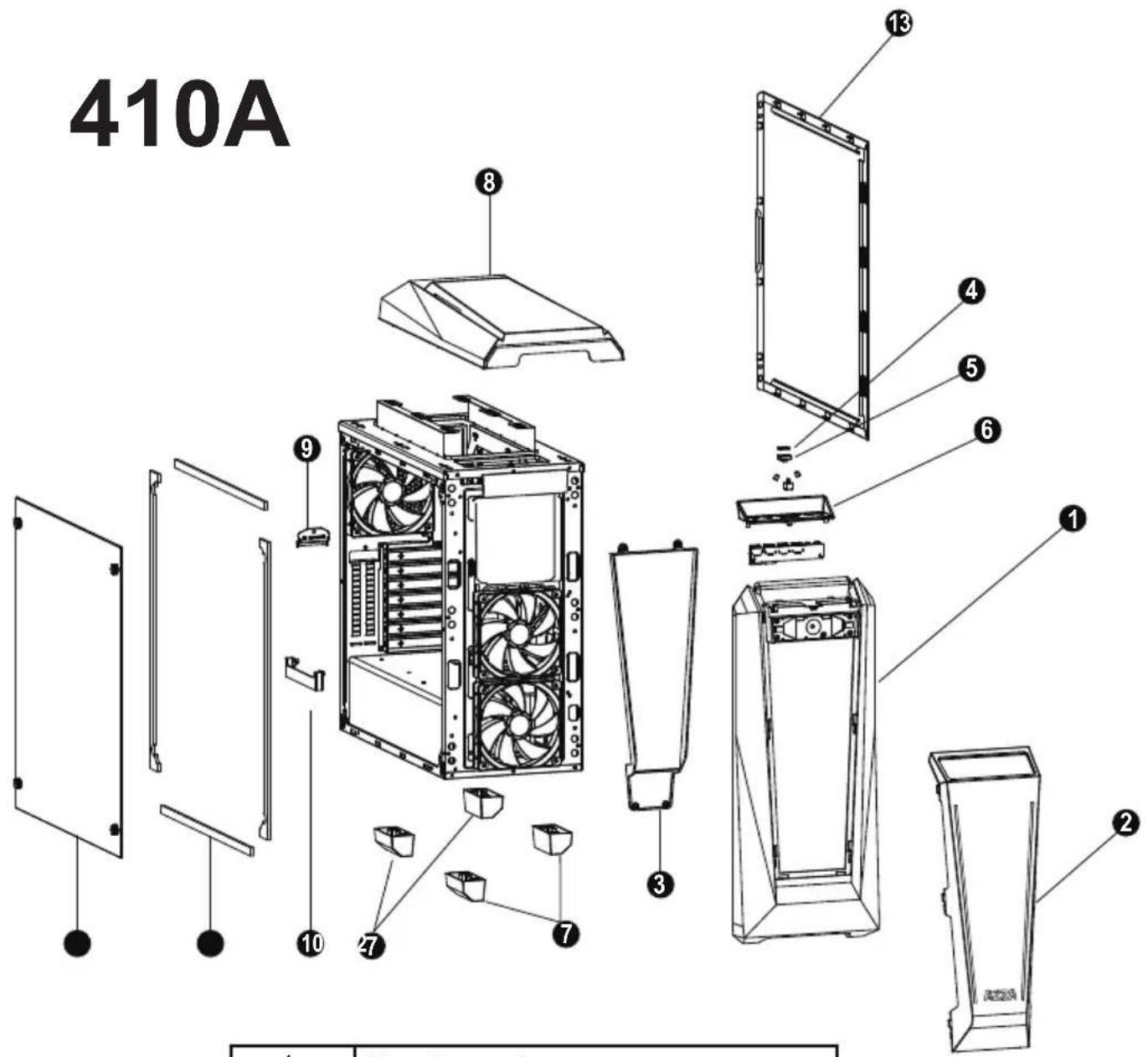
410A
text_image
410A ① ② ③ ④ ⑤ ⑥ ⑦ ⑧ ⑨ ⑩ ⑪| 1 | Front panel |
| 2 | Panel transparent plate |
| 3 | Panel reflector |
| 4 | Power button |
| 5 | Transparent power button holder |
| 6 | USB fixed plate |
| 7 | Case feet x4 |
| 8 | Top panel |
| 9 | PCIe cover plate |
| 10 | PCIe cradle |
| 11 | Side plate EVA crash pad x4 |
| 12 | Left glass |
| 13 | Right side panel |
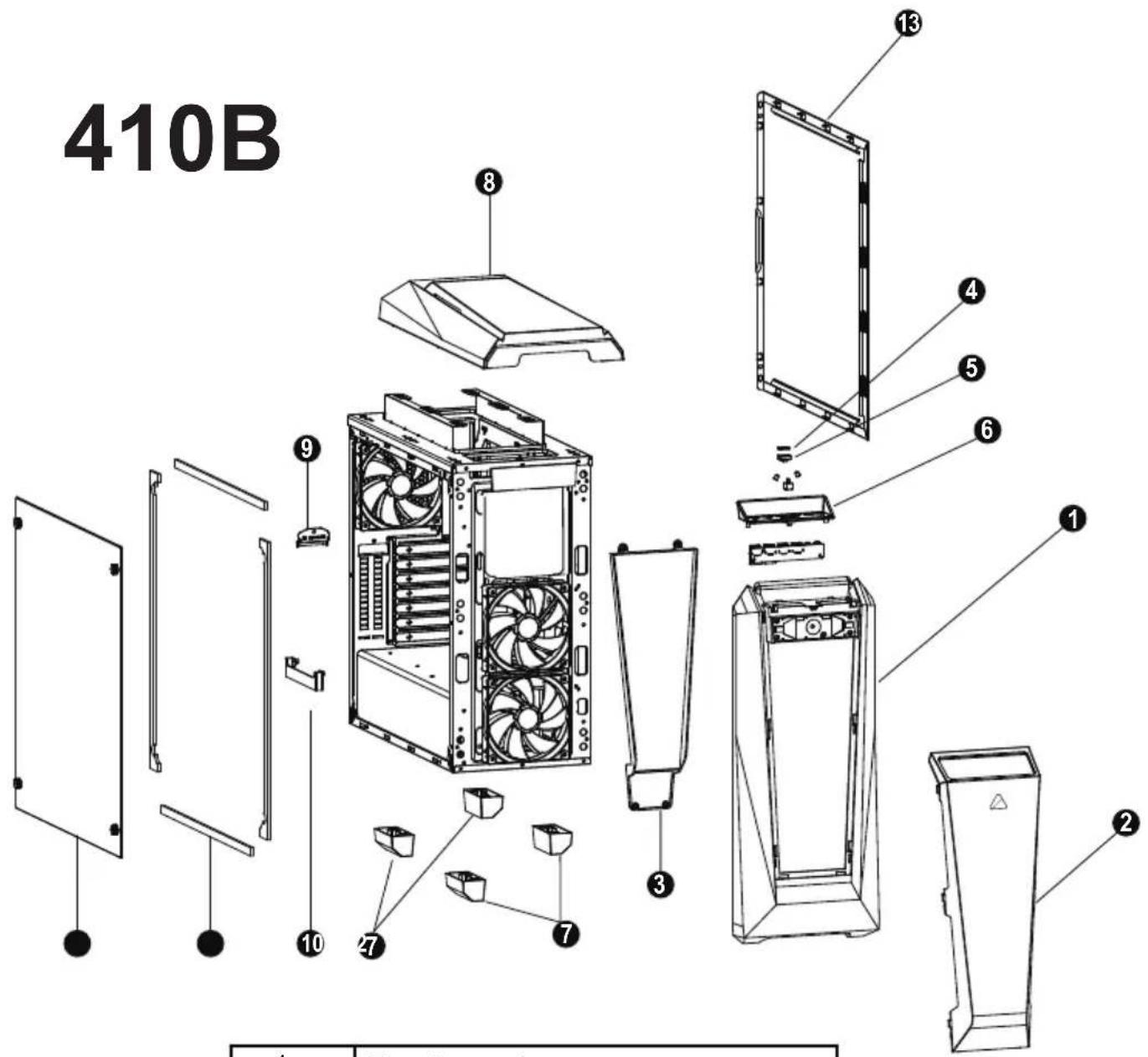
410B
text_image
410B| 1 | Front panel |
| 2 | Panel transparent plate |
| 3 | Panel reflector |
| 4 | Power button |
| 5 | Transparent power button holder |
| 6 | USB fixed plate |
| 7 | Case feet x4 |
| 8 | Top panel |
| 9 | PCIe cover plate |
| 10 | PCIe cradle |
| 11 | Side plate EVA crash pad x4 |
| 12 | Left glass |
| 13 | Right side panel |
natural_image
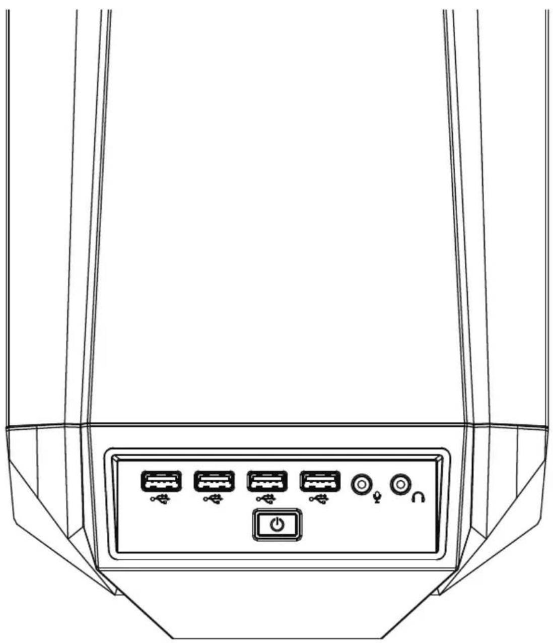
Line drawing of a device rear panel with six labeled buttons and a power button (no text or symbols) | Power |
 | USB3.0 (Blue) |
 | USB2.0 (Black) |
 | Mic |
 | Audio |
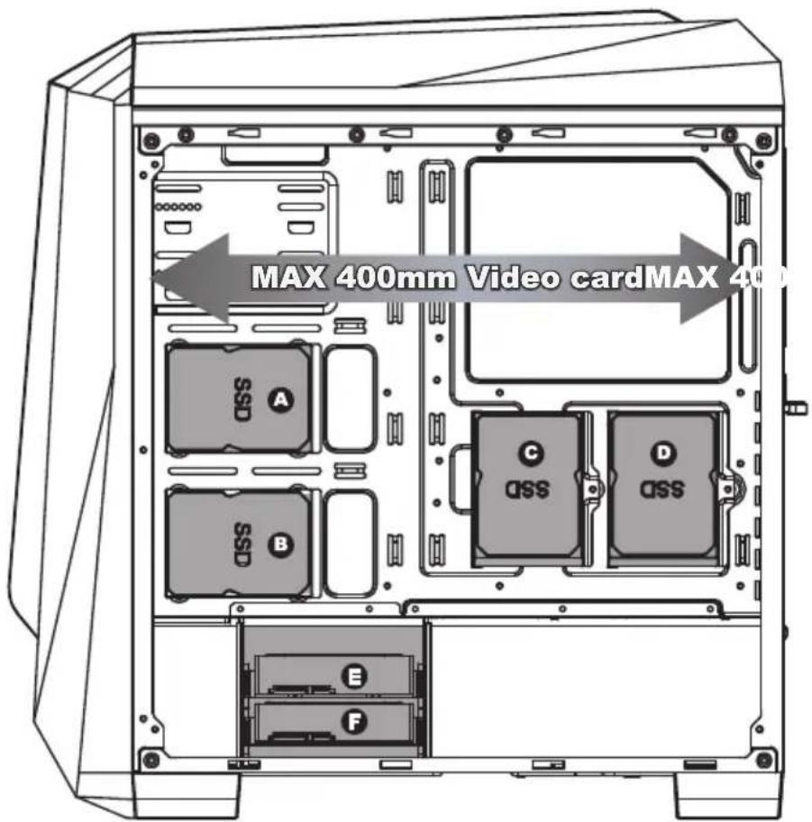
- Supports up to 400mm long Video cards.
- Two mounting holes support 2.5" devices.

- Two brackets support 2.5" devices.
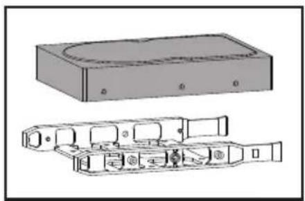
- Two multifunctional trays support 3.5" HDD or 2.5" SSD.
natural_image
Technical line drawing of a mechanical housing assembly (no text or symbols)Multifunctional bracket.

natural_image
Technical line drawing of a mechanical or electronic device with no visible text or symbolsSecure 2.5" SSD / HDD with screws.

natural_image
Diagram of a rectangular electronic device with internal components and mounting ports (no text or symbols)Secure 3.5" HDD with screws.
Front
natural_image
Simple upward-pointing arrow graphic with gradient shading (no text or symbols)Max Height of Water Cooling
360 mm

natural_image
Simple black downward arrow symbol on white background (no text or labels)
natural_image
Technical diagram of a server rack with internal components and mounting feet (no text or labels)120mm x3
natural_image
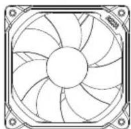
Line drawing of a fan with blades and central hub, enclosed in a square frame (no text or symbols)
natural_image
Technical line drawing of a fan with blades radiating from center, no text or symbols present
natural_image
Line drawing of a computer fan with blades and central hub (no text or symbols)Top

natural_image
Simple black arrow pointing left on white background (no text or symbols)Max Length of Water Cooling
240 mm
120mm x2
natural_image
Technical line drawing of a fan with blades and mounting brackets (no text or symbols)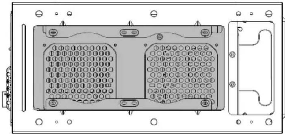
natural_image
Technical line drawing of a device rear panel with hexagonal grid and mounting holes (no text or symbols)
natural_image
Line drawing of a computer fan with blades and mounting brackets (no text or symbols)
text_image
RGB1 RGB2 1 +12V 2 G 3 R 4 B Digital RGB 1 +5V 2 Data 3 No Pin Ground RGB Motherboard SYS_FAN RGB1 Digital RGB All lighting modes are controlled by motherboard software. Expansion Connector Digital RGBParallel Connection ("daisy-chaining")
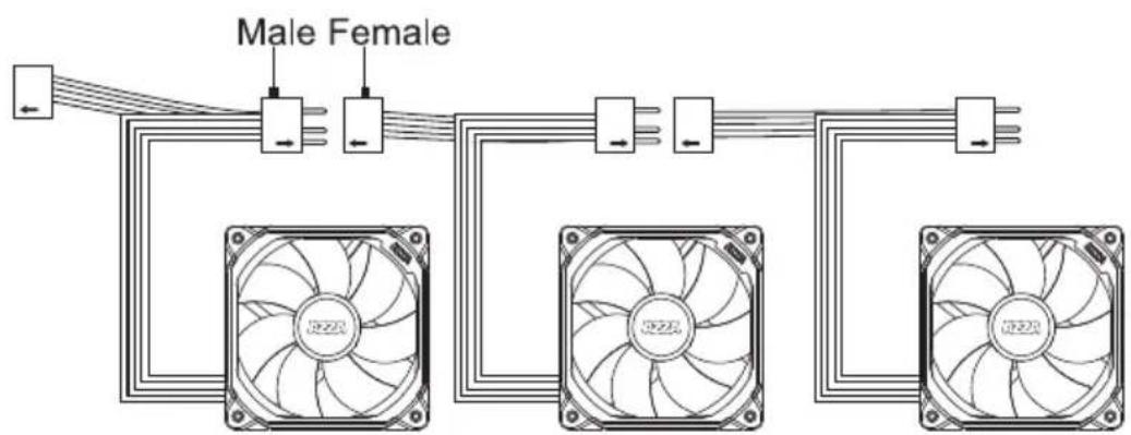
text_image
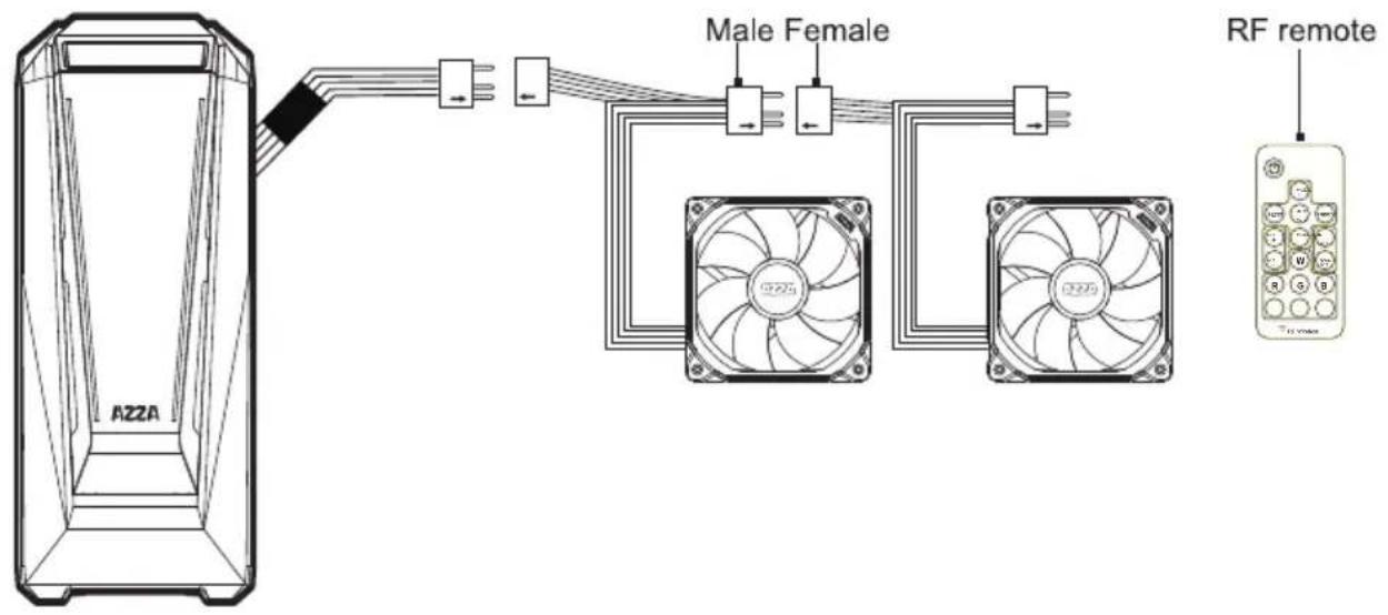
Male Female
CAUTION
If you do not have a motherboard that is compatible with digital RGB, then you can opt to use the included RF remote and receiver.
The addressable RGB fan has a 3-pin connector (4 holes). Please ensure that you are connecting the 3-pin connector on the fan to the 3-pin RGB header on the motherboard or RF Remote connector.
Do not plug it into the 4-pin header, as the incompatible voltage will fry the fan. The 3-pin connector on the fan still has 4 holes, but the 4th hole is intentionally blocked, for this reason, so please do not try to force it!
Our digital RGB devices are WS2812B-compliant. Each fan contains 18 digital/addressable LED diodes. The WS2812B standard supports up to 60 diodes at the maximum for a single header, so please do not daisy-chain more than 3 digital RGB fans together.
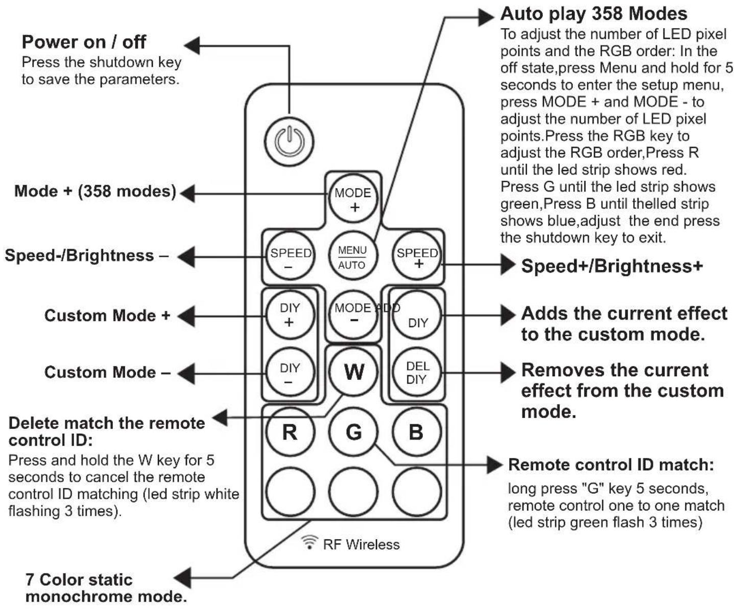
text_image
Power on / off Press the shutdown key to save the parameters. Mode + (358 modes) Speed-/Brightness - Custom Mode + Custom Mode - Delete match the remote control ID: Press and hold the W key for 5 seconds to cancel the remote control ID matching (led strip white flashing 3 times). 7 Color static monochrome mode. RF Wireless Auto play 358 Modes To adjust the number of LED pixel points and the RGB order: In the off state,press Menu and hold for 5 seconds to enter the setup menu, press MODE + and MODE - to adjust the number of LED pixel points.Press the RGB key to adjust the RGB order,Press R until the led strip shows red. Press G until the led strip shows green,Press B until theelled strip shows blue,adjust the end press the shutdown key to exit. Speed+/Brightness+ Adds the current effect to the custom mode. Removes the current effect from the custom mode. Remote control ID match: long press "G" key 5 seconds, remote control one to one match (led strip green flash 3 times)The first Digital RGB fan is to be connected to the Digital RGB LED RF remote in the chassis, while the rest of them can be daisy chained to the first one with their own male and female plugs.