KAMMTARTTPA - Vacuum Cleaner Kogan - Free user manual and instructions
Find the device manual for free KAMMTARTTPA Kogan in PDF.

User questions about KAMMTARTTPA Kogan
0 question about this device. Answer the ones you know or ask your own.
Ask a new question about this device
Download the instructions for your Vacuum Cleaner in PDF format for free! Find your manual KAMMTARTTPA - Kogan and take your electronic device back in hand. On this page are published all the documents necessary for the use of your device. KAMMTARTTPA by Kogan.
USER MANUAL KAMMTARTTPA Kogan
natural_image
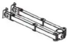
Mechanical assembly with vertical and horizontal black components, no visible text or symbolsARTICULATING TRIPLE MONITOR ARM
(SUITABLE FOR MONITORS 17-27")
KAMMTARTTPA
SAFETY & WARNINGS
Read the entire user guide before you commence installation and assembly. If you do not understand these directions or if you have any doubts about the safety of the installation, contact a qualified technician.
CAUTION: Use with products heavier than the rated weights indicated may result in instability causing possible injury.
- Ensure that you have received all parts according to the component checklist prior to installation. If any parts are missing or faulty, contact help.Kogan.com for support.
- Closely follow the assembly instructions. Improper installation may result in property damage or serious personal injury.
- Do not use this product for any purpose that is not explicitly specified in this guide.
- Do not exceed the weight capacity.
-
Serious or fatal injuries can occur from tip over. To prevent tip over:
-
Never allow children to climb, stand, hang or play on any part or monitor or stand.
-
Use tip over restraint or anchor stand to wall.
-
Use the mounting screws provided and DO NOT OVER TIGHTEN mounting screws.
- This product contains small items that could be a choking hazard if swallowed. Keep these items away from children.
- This product is intended for indoor use only. Using this product outdoors could lead to product failure and personal injury.
- Use of tip-over restraints may reduce but not eliminate the risk of tip-over.
- Small parts are not suitable for children under 3 years. Adult supervision is required.
IMPORTANT: Ensure that you have received all parts according to the component checklist prior to installation. If any parts are missing or faulty, contact your place of purchase for a replacement.
MAINTENANCE: Check that the product is secure and safe use at regular intervals (at least every three months).

text_image
75x75/100x100 MAX 27" 8kg x3 RATEDCOMPONENTS
natural_image
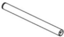
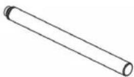
Simple line drawing of a cylindrical object with rounded ends and a small protrusion at the end (no text or symbols)A1 Lower pole
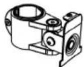
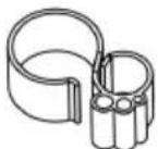
B C-Clamp
D2 Monitor arm
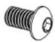
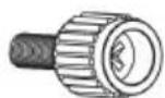
G M8x12 Bolt (x2)
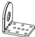
J Support plate

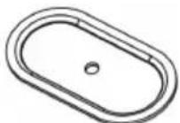
M Grommet base plate

- Allen key

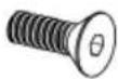
R M4x30 Bolt (x12)
C Clamp brace

E VESA plate (x3)

H Nut (x3)
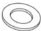
KM10 washer
N1 Wire clip (x2)
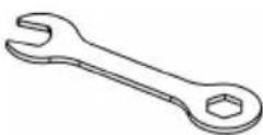
P Spanner
natural_image
Simple line drawing of a cylindrical object with rounded ends and a central hole (no text or symbols)A2 Upper pole
D1 Swivel arm
F M5x14 Bolt (x3)

I M10 Bolt
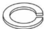
L Spring washer
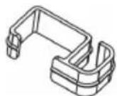
N2 Wire clip (x4)
Q M4x12 Bolt (x12)
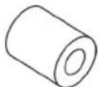
S M4 Spacer (x12)
INSTALLATION
Step 1:
Loosen the screw on the Lower Pole (A1) with Allen key 2mm (O). Connect Lower Pole (A1) to Upper Pole (A2) and tighten the screw with Allen key 2mm (O) to secure the two poles.

text_image
A1 O A2 A2 A1 OStep 2:
Option A: Clamp Installation
- Connect Lower Pole (A1) and C-Clamp Brace (C) from the bottom using M5x14 Bolt (F) and tighten with Allen Key 3mm (O).
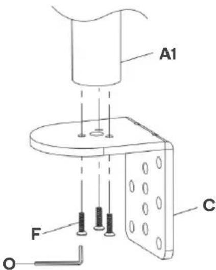
text_image
A1 F C O- Select the preferred height according to your desk thickness. Connect C-Clamp (B) to C-Clamp Brace (C) using M8 x 12 Bolt (G) and tighten with Allen Key 5mm (O). Rotate the hand knob clockwise to fasten for stability.
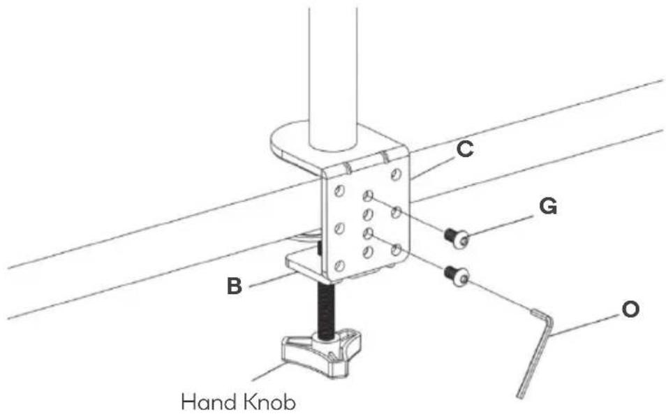
text_image
C B G O Hand KnobOption B: Grommet Base Installation
- Place Lower Pole (A1) onto Grommet Base Plate (M). Connect them from the bottom using M5x14 Bolt (F) and tighten with Allen Key 3mm (O).
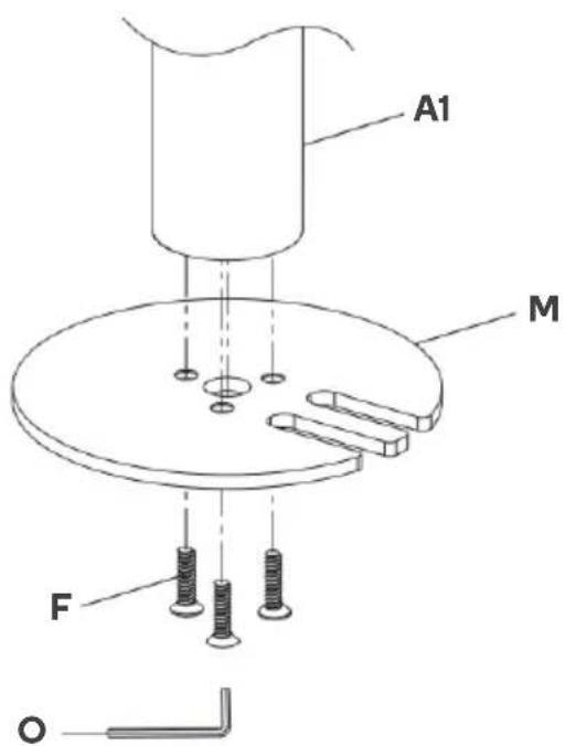
text_image
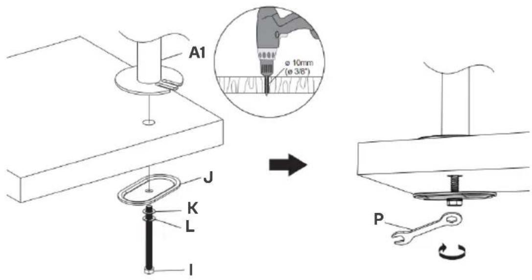
A1 M F O2a: Existing Grommet Hole Installation
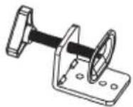
If the existing grommet hole comes with a plastic protector, remove it to ensure a flat surface before installing the desk mount. Position the Lower Pole (A1) on the mounting surface and secure using the Support Plate (J), M10 Washer (K), Spring Washer (L) and M10 Bolt (I). Fasten the Bolt using the provided Spanner (P).
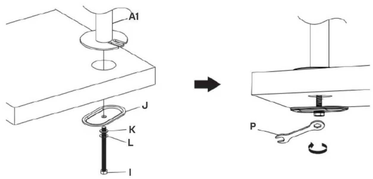
text_image
A1 J K L I P2b: Self-drilled Grommet Hole Installation
Mark the position of the hole on your mounting surface. Drill a 3/8"(10mm) diameter hole at the marked position through the mounting surface. Position the Lower Pole (A1) on the mounting surface and secure using the Support Plate (J), M10 Washer (K), Spring Washer (L) and M10 Bolt (I). Fasten the Bolt using the provided Spanner (P).
text_image
A1 ø 10mm (ø 3/8") J K L I PStep 3:
Put the Wire Clip (N1) and Arms (D1) & (D2) through the Poles (A1) & (A2) adjust the preferred height and tighten using Allen Key 5mm (O). Attach the Wire Clips (N2) to the Swivel Arm (D).

text_image
D2 D1 N1 N2Step 4:
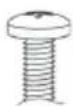
4.1: Select Monitor Screws
Note: Only one screw size fits your Monitor
Hand thread screws into the threaded inserts on the back of your Monitor to determine which screw (M4 x 12 or M4 x 30) to use.

M4x12 M4x30
natural_image
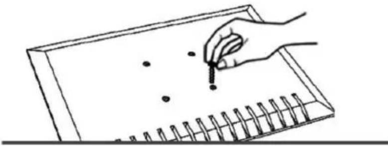
Line drawing of a hand holding a pencil over a grid notebook with dots (no text or symbols)4.2: Select Spacers (if needed)
Not required
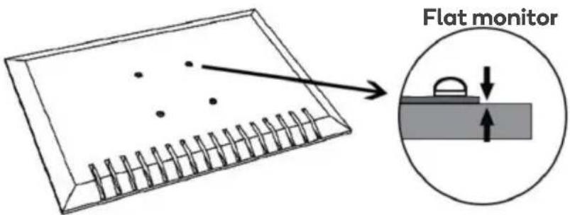
text_image
Flat monitorRequired for
Inset holes
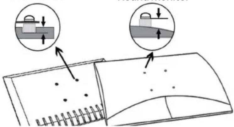
text_image
Diagram illustrating a mechanical or structural assembly with labeled components and directional arrows indicating movement or force.Round monitor
4.3: Flat Back Monitor

text_image
E Q4.4: Curved or Recessed Back Monitor
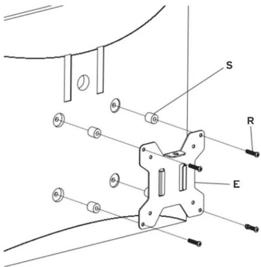
text_image
S R EStep 5:
Place the assembled TV/Monitor onto the Arms (D1) & (D2) and tighten the VESA Plate (E) with Nut (H) for stability.

text_image
Technical diagram of a mechanical assembly with labeled components and directional arrows indicating movement or force.Step 6:
If one monitor is lower, remove the Nut (H) and turn the bolt counterclockwise using Allen key 3mm (O) to raise the monitor. Tighten the VESA Plate (E) with Nut (H) for stability after the adjustment.
Note: Ignore this step if monitors are level.
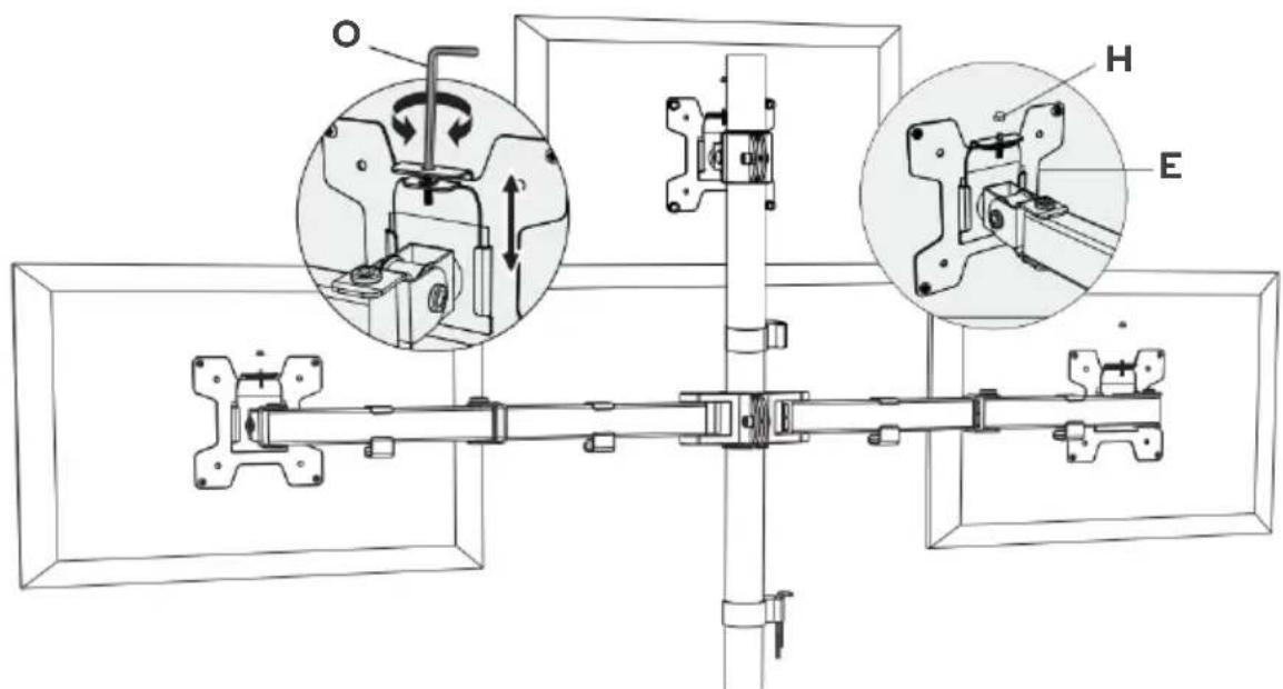
text_image
Technical diagram of a mechanical assembly with labeled components O, H, and E, showing internal mechanisms and assembly details.Step 7:
Guide the cable through the Wire Clips (N1) & (N2) and store the Allen Keys (O) in the Wire Clip (N1). Adjust the tilt angle using Allen Key 5mm (O).

text_image
N2 O N2Step 8:
Manually swivel, tilt and rotate the monitor for the best viewing angle.
Note: Ensure the security Nut (H) is installed before you rotate the monitor.
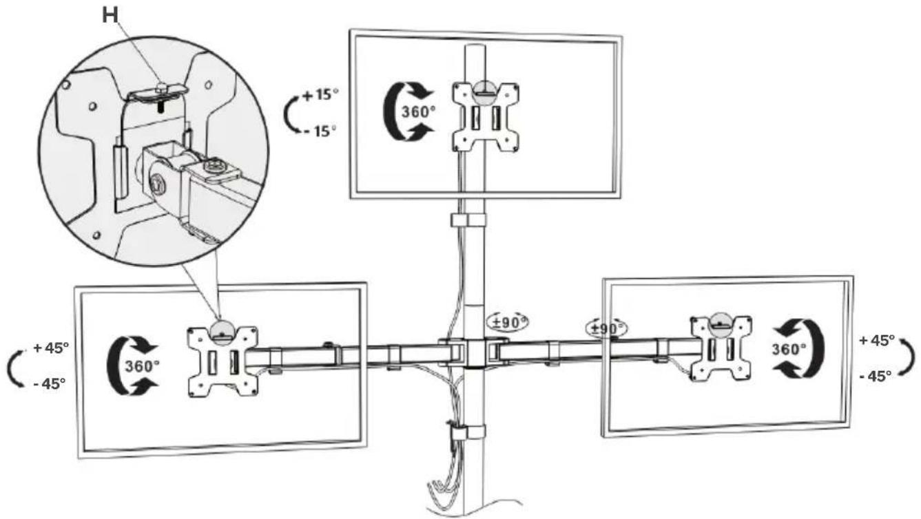
text_image
H +15° -15° 360° +45° -45° 360° ±90° ±90° 360° +45° -45°Need more information?
We hope that this user guide has given you the assistance needed for a simple set-up.
For the most up-to-date guide for your product, as well as any additional assistance you may require, head online to help.kogan.com
kogan.com