AXPIO-ES1 - Television AXESS - Free user manual and instructions
Find the device manual for free AXPIO-ES1 AXESS in PDF.

User questions about AXPIO-ES1 AXESS
0 question about this device. Answer the ones you know or ask your own.
Ask a new question about this device
Download the instructions for your Television in PDF format for free! Find your manual AXPIO-ES1 - AXESS and take your electronic device back in hand. On this page are published all the documents necessary for the use of your device. AXPIO-ES1 by AXESS.
USER MANUAL AXPIO-ES1 AXESS
natural_image
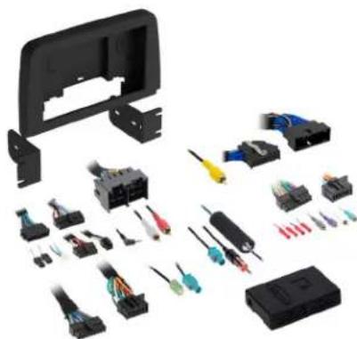
Collection of various electronic components and connectors laid out on a white background (no text or symbols visible)Ford Escape 2020-2022
Visit AxxessInterfaces.com for more detailed information about the product and up-to-date vehicle specific applications.
KIT FEATURES
- Designed for Pioneer DMH-WC5700NEX receivers
- Allows for the retention and adjustment of the factory personalization menu through the Pioneer radio
- All HVAC functions will be retained (KIT FEATURES cont. on next page)
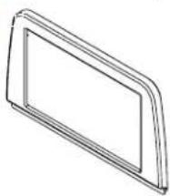
KIT COMPONENTS
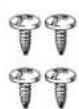
- A) Front trim panel - B) Back panel - C) Pioneer chassis brackets - D) Pioneer display brackets - E) #8 x 3/8" Phillips screws (4)
Not Shown: Radio Interface, LD-FD3-PIO, LD-FD54CAM, AD-EU5, 40-GPS-PIO, PRO4AVIC-PIO / PRO4-PIORCA
A
natural_image
Simple line drawing of a rectangular frame or panel with no text or symbols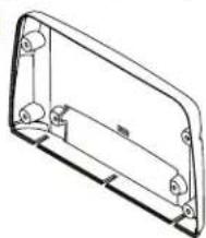
natural_image
Technical line drawing of a rectangular mechanical housing or enclosure with mounting holes and internal components (no text or symbols)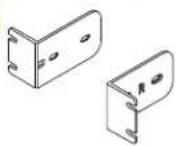

The image is too blurry to recognize any text content.
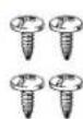
TABLE OF CONTENTS
Dash Disassembly....3-6
Kit Assembly 7-8
Axxess Wiring Installation....9
Radio Preparation....10-11
Final Assembly....12
WIRING & ANTENNA CONNECTIONS
Wiring Harness: Included with Kit
Antenna Adapter and
GPS Antenna Adapter: Included with Kit RGB Extension Cable: Pioneer part # CD-RGB150A (not sold by Metra)
TOOLS REQUIRED
- Panel removal tool • Phillips screwdriver
- 7mm Socket wrench
ATTENTION: With the key out of the ignition, disconnect the negative battery terminal before installing this product. Ensure that all installation connections, especially the air bag indicator lights, are plugged in before reconnecting the battery or cycling the ignition to test this product.
NOTE: Refer also to the instructions included with the aftermarket accessory before installing this device.
KIT FEATURES (CONT.)
KIT FEATURES (cont. from cover)
- Single-Zone vehicles will only get status feedback of the HVAC functions, while Dual-Zone vehicles can also be controlled through the radio screen.
- Allows for the retention and adjustment of the factory personalization menu through the Pioneer® radio.
- Complete plug-n-play installation
- Includes dash kit with Axxess interface and vehicle-specific T-harness
- Includes radio antenna adaptor for GPS
- Provides a built-in STOP/START engine override (if equipped)
- Provides accessory power (12V 10-amp)
- Provides NAV outputs (parking brake, reverse, and speed sense)
- Retains audio controls on the steering wheel
• Works in both single and dual-zone vehicles - Dash kit is painted scratch-resistant matte black to match the factory finish
- Retains safety chimes through an included off-board speaker
- Designed for non-amplified vehicles
- Micro "B" USB updatable
DASH DISASSEMBLY
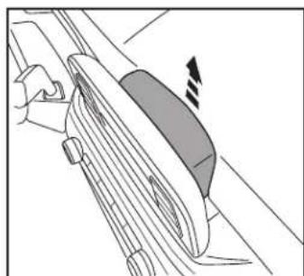
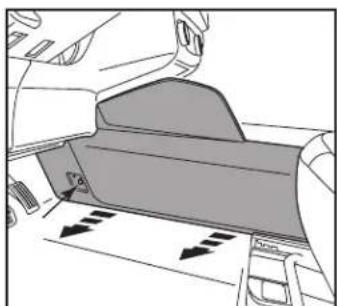
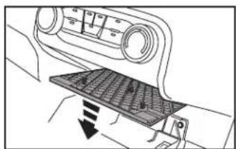
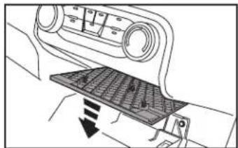
- Unclip and remove the trim panel behind the factory radio screen. (Figure A)
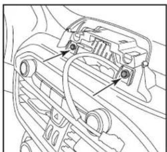
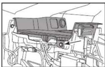
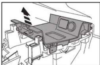
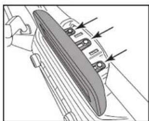
- Remove (3) 7mm screws under cover removed in step 1 then unclip and remove the screen. (Figure B)
natural_image
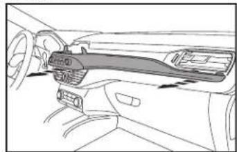
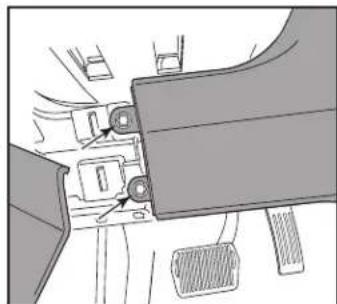
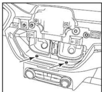
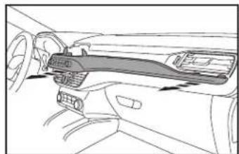
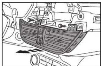
Diagram of a hand using a tool to interact with a mechanical component, showing no text or symbols.- Remove (2) 7mm screws behind factory screen then Unclip and remove the trim panel containing the radio controls and extending over to passenger side air vent (Figure C, D).
Continued on the next page

natural_image
Mechanical component diagram showing a curved housing with mounting holes and directional arrows indicating assembly or force (no text or symbols present)(Figure B)
natural_image
Technical line drawing of a car engine compartment with no visible text or symbols(Figure C)(Figure A)
natural_image
Line drawing of a car interior showing dashboard and steering wheel (no text or symbols)(Figure D)
DASH DISASSEMBLY (CONT.)
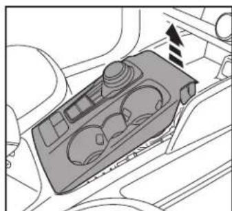
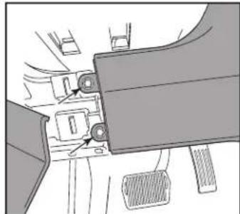
- Unclip and remove the top of the console including the cup holders and shifter. (Figure E)
Note: Start at the front of the console. There are hooks on trim panel so be careful when removing. - Unclip and let the left side of the knee bolster panel hang then remove (2) 7mm exposed on right side of panel. (Figure F)
natural_image
Interior view of a car dashboard with control panel and directional arrow (no text or symbols)(Figure E) (Figure G)
- Remove the screw cover on the driver's side center console panel then remove the (1) 7mm screw exposed. (Figure G)
- Unclip and remove the console side trim panel. (Figure G)
- Unclip and remove the console side trim panel from the passenger side.
(Figure H)
Continued on the next page
natural_image
Diagram of a car interior showing dashboard and seat area with directional arrows (no text or symbols)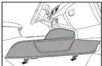
natural_image
Diagram of a vehicle interior showing dashboard and seat components (no text or symbols)(Figure H)
natural_image
Mechanical assembly diagram showing a belt switch and lever mechanism (no text or labels)(Figure F)
DASH DISASSEMBLY (CONT.)
- Remove (2) 7mm bolts (one on each side) securing the USB trim panel then unclip, unplug and remove the panel. (Figures I, J, K)
natural_image
Technical line drawing of a mechanical assembly with no visible text or symbols(Figure I) (Figure L)
-
Unclip and remove the climate control lower trim panel then remove the (2) 7mm bolts securing the climate control trim panel. (Figure L, M)
-
Remove (2) 7mm bolts securing the air vents then unclip and remove them. (Figure N)
Continued on the next page
natural_image
Diagram of a car interior showing a vehicle's seatbelt and dashboard (no text or symbols)
natural_image
Technical line drawing of a mechanical component with internal compartments and mounting holes (no text or symbols)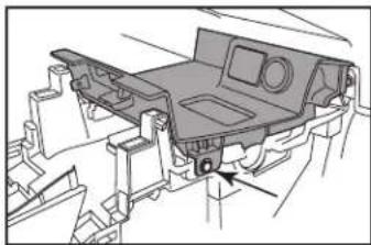
natural_image
Technical line drawing of a vehicle chassis frame with no visible text or symbols(Figure J) (Figure M)
natural_image
Technical diagram of a vehicle chassis with internal compartments and a directional arrow indicating motion (no text or symbols present)(Figure K) (Figure N)

natural_image
Technical line drawing of a car air vent assembly (no text or symbols)DASH DISASSEMBLY (CONT.)
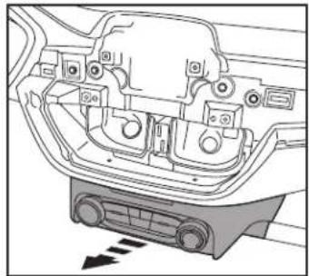
- Remove (2) 7mm bolts securing the climate control trim panel under the air vents. (Figure 0)
- Unclip, unplug and remove the climate control trim panel. (Figure P)
natural_image
Technical line drawing of a car interior showing structural components and mounting points (no text or labels)(Figure 0)
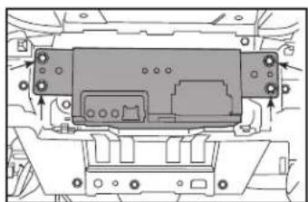
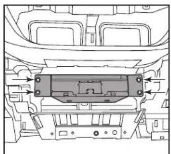
- Remove (4) 7mm screws securing the radio chassis to the subdash then unplug and remove chassis. (Figure Q) Continue to Kit Assembly
natural_image
Technical line drawing of a mechanical component with mounting holes and internal structure (no text or symbols)(Figure Q)
natural_image
Technical diagram of a car interior showing engine compartment and dashboard (no text or labels)(Figure P)
KIT ASSE MB LY
Note: For steps 1 and 5, reference the installation manual provided with the radio for which hardware to use. The display screen and radio chassis use two different types of screws.
- Secure the display screen to the Pioneer display brackets using (4) screws supplied with the radio. (Figure A)
- Connect the RGB extension cable to the display, then route the cable through the opening in the radio display back panel. Secure the screen/bracket assembly to the radio display back panel using (2) screws supplied with the radio. (Figure B)

natural_image
Technical diagram of a device with two labeled components and dashed alignment lines (no text or symbols)(Figure A) (Figure C)
- Secure the radio display front panel to the back panel/radio display assembly using (4) #8 x 3/8" Phillips screws provided. (Figure C)
- Route the RGB extension cable downward to where the radio chassis will be mounted to the sub dash. Set the screen assembly on top of the dash for now. Continued on the next page

natural_image
Technical diagram of a door frame assembly with directional arrows indicating movement (no text or symbols)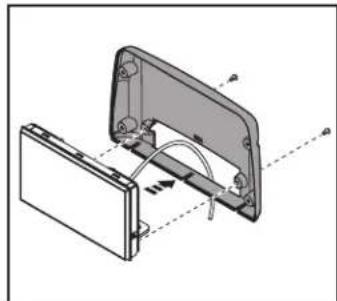
natural_image
Technical diagram of a mechanical assembly with labeled components and motion arrows (no text or symbols)(Figure B)
KIT ASSEMBLY (CONT.)
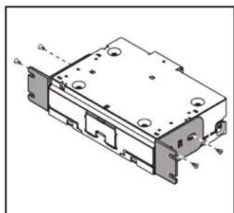
- Secure the Pioneer chassis brackets to the radio chassis using (4) screws supplied with the radio. (Figure E)
- Connect the RGB extension cable from step 4 to the Pioneer chassis RGB cable. Slide the radio chassis into the factory chassis location. (Figure F)
Continue to Axxess Wiring Section
natural_image
Technical line drawing of a mechanical component with mounting holes and housing (no text or symbols)(Figure E) (Figure F)
natural_image
Technical line drawing of a vehicle chassis with internal components and directional arrows (no text or symbols)AXXESS WIRING INSTALLATION

text_image
NOTE: Used in all applications except Ford Transit/Transit Connect 2020-up Video Ground CAN 2 LD-FD54CAM NOTE: No Connection AXXESS INTERFACE 16P 28P Fuse EXT SPRR N/A CAN 3 "TBA" WIRES 40-GPS-PIO PRO4-PIORCA Low-level 18P (M) 18P (F) Pioneer Harness LD-FD3-PIO GPS 4-PIN MIC HDMI STATUS ANT AUX (INCL. W/RADIO) Center Channel AUTO Camera NOTE: Only used in the Ford Transit/Transit Connect 2020-Up AD-EU5 CARSIDE CONNECTORSREV. 7/30/24 INSTAXPIO-ES1
RADIO PREPARATION
Vehicle Selection – Allows you to select the vehicle the radio is being installed in.
- Vehicle type must be selected to activate menu & HVAC functions, as well as steering wheel controls. Press Make to change the vehicle type. Then press Confirm. The radio will then reset and lock in the selected vehicle.
| Vehicle Selection | |
| Make | No Selection |
| Model | |
| Trim | |
| Save to Flash and Restart | Confirm |
| Vehicle Selection | |
| Make | Ford |
| Model | Escape |
| Trim | All |
| Save to Flash and Restart | Confirm |
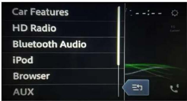
Car Features – The source for accessing all vehicle information and options.
text_image
Car Features HD Radio Bluetooth Audio iPod Browser AUX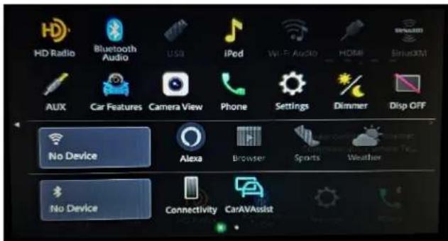
text_image
HD Radio Bluetooth Audio USA iPod Wi-Fi Audio HDMI SiHoXM AUX Car Features Camera View Phone Settings Dimmer Disp OFF No Device Alexa Browser Sports Weather No Device Connectivity CarAVAssist
Metra
RADIO PREPARATION (CONT)
HVAC Operation – HVAC Status and Control Screen.
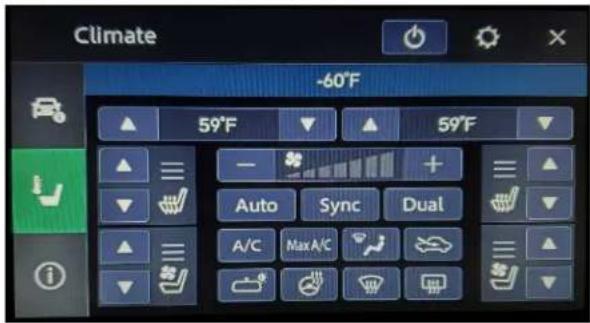
text_image
Climate -60°F 59°F 59°F Auto Sync Dual A/C Max A/CVehicle Info Screen – Displays various information of the vehicle (TPMS, Park Position, Lights).
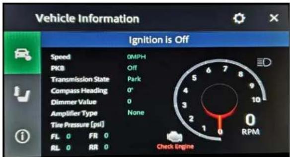
text_image
Vehicle Information Ignition is Off Speed 0MPH PKB Off Transmission State Park Compass Heading 0° Dimmer Value 0 Amplifier Type None Tire Pressure (pvl) FL 0 FRI 0 RL 0 RR 0 Check EngineCustomizations Menu – Allows full control of vehicle personalization options.
- Access this menu by selecting the gear icon on the previous screenshot.
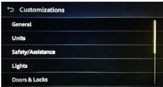
text_image
Customizations General Units Safety/Assistance Lights Doors & LocksAbout Screen – Feedback screen for interface software information.
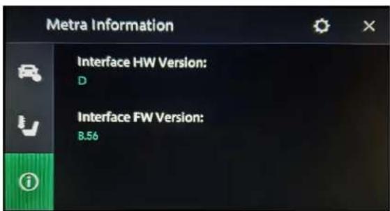
text_image
Metra Information Interface HW Version: D Interface FW Version: 8.56FINAL ASSEMBLY
- Using the factory screws, secure the chassis assembly to the dash where the factory chassis was located. (Figure A)
- Reassemble the dash in reverse order of disassembly. (Figure B)

natural_image
Technical line drawing of a mechanical housing or enclosure with mounting holes and internal components (no text or symbols)(Figure A)

natural_image
Mechanical assembly diagram showing a lever and gear mechanism with no visible text or symbols(Figure B)
Having difficulties? We're here to help.
Contact our Tech Support line at:
386-257-1187
Or via email at:
techsupport@metra-autosound.com
Tech Support Hours (Eastern Standard Time)
Monday - Friday: 9:00 AM - 7:00 PM
Saturday: 10:00 AM - 5:00 PM
Sunday: 10:00 AM - 4:00 PM

MECP
MOBILE ELECTRONICS
CERTIFIED PROFESSIONAL
Metra recommends MECP certified technicians
natural_image
Disassembled electronic component parts including a black plastic housing, various connectors, and screwdrivers (no text or symbols visible)Ford Escape 2020-2022
natural_image
Simple line drawing of a rectangular frame or panel with no text or symbols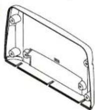
natural_image
Technical line drawing of a mechanical housing or enclosure component (no text or symbols)

ÍNDICE
natural_image
Diagram of a hand using a tool to cut a mechanical component, showing a circular feature with an arrow indicating motion (no text or symbols present)natural_image
Mechanical assembly diagram showing a clamping device with mounting holes and directional arrows (no text or labels)(Figura B)

natural_image
Technical line drawing of a car engine component with no visible text or symbols(Figura C)(Figura A)
natural_image
Line drawing of a car interior showing dashboard and steering wheel (no text or symbols)(Figura D)
DESMONTAJE DEL TABLERO (CONT.)
natural_image
Top-down diagram of a car air intake manifold showing vent, drum, and dashboard (no text or labels)(Figura E) (Figura G)
natural_image
Mechanical assembly diagram showing a lever mechanism with pulleys and a belt (no text or symbols)(Figura F)
natural_image
Diagram of a car interior showing dashboard and seat area with directional arrows indicating movement (no text or symbols)
natural_image
Diagram of a vehicle interior showing dashboard and seat components with directional arrows (no text or labels)(Figura H)
DESMONTAJE DEL TABLERO (CONT.)
natural_image
Technical line drawing of a mechanical assembly with no visible text or symbolsnatural_image
Technical line drawing of a vehicle chassis frame with no visible text or symbols(Figura J) (Figura M)
natural_image
Diagram of a car interior showing a vehicle's seatbelt and dashboard (no text or symbols)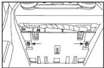
natural_image
Technical line drawing of a mechanical assembly with no visible text or symbols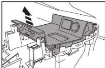
natural_image
Technical diagram of a vehicle chassis frame with no visible text or symbols(Figura K) (Figura N)
natural_image
Technical line drawing of a car air vent assembly (no text or symbols)DESMONTAJE DEL TABLERO (CONT.)
natural_image
Technical line drawing of a car interior showing structural components and mounting points (no text or labels)(Figura 0)
natural_image
Technical line drawing of a mechanical component with mounting holes and internal structure (no text or symbols)(Figura Q)

natural_image
Technical diagram of a car interior showing engine compartment and dashboard (no text or labels)(Figura P)
ENSAMBLE DEL KIT
natural_image
Technical diagram of a device with two labeled components and dashed alignment lines (no text or symbols)(Figura A) (Figura C)
natural_image
Technical diagram of a door frame assembly with directional arrows indicating movement (no text or symbols)
natural_image
Technical diagram of a mechanical assembly with labeled components and motion arrows (no text or symbols)(Figura B)
ENSAMBLE DEL KIT (CONT.)
natural_image
Technical line drawing of a mechanical component with mounting holes and housing (no text or symbols)(Figura E) (Figura F)

natural_image
Technical line drawing of a vehicle chassis with internal components and directional arrows (no text or symbols)| Vehicle Selection | |
| Make | No Selection |
| Model | |
| Trim | |
| Save to Flash and Restart | Confirm |
| Vehicle Selection | |
| Make | Ford |
| Model | Escape |
| Trim | All |
| Save to Flash and Restart | Confirm |
text_image
HD Radio Bluetooth Audio USB iPod Wi-Fi Audio HDMI SINADIM AUX Car Features Camera View Phone Settings Dimmer Disp OFF No Device Alexa Browser Sports Weather No Device Connectivity CarAVAssist
Metra
text_image
Vehicle Information Ignition Is Off Speed 0MPH PKB Off Transmission State Park Compass Heading 0° Dimmer Value 0 Amplifier Type None Tire Pressure (psi) FL 0 FIR 0 RL 0 RR 0 Check Enginetext_image
Customizations General Units Safety/Assistance Lights Doors & Lockstext_image
Metra Information Interface HW Version: D Interface FW Version: B.56natural_image
Technical drawing of a mechanical housing or enclosure with mounting holes and internal components (no text or symbols)(Figura A)
natural_image
Mechanical assembly diagram showing a hand holding a component with arrows pointing to specific parts (no text or symbols present)(Figura B)