99-3303 - Car Radio AXESS - Free user manual and instructions
Find the device manual for free 99-3303 AXESS in PDF.

User questions about 99-3303 AXESS
0 question about this device. Answer the ones you know or ask your own.
Ask a new question about this device
Download the instructions for your Car Radio in PDF format for free! Find your manual 99-3303 - AXESS and take your electronic device back in hand. On this page are published all the documents necessary for the use of your device. 99-3303 by AXESS.
USER MANUAL 99-3303 AXESS
• DIN radio provision with driver information center (DIC)
• ISO DIN radio provision with driver information center (DIC)
- Painted to match factory dash

natural_image
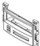
Front panel of a CD-ROM drive showing front latches and control buttons (no readable text or symbols)KIT COMPONENTS
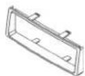
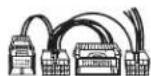
• A) Radio housing • B) ISO brackets • C) ISO trim plate • D) (9) DIN spacer • E) Wire harness
A
B

C
D

E
WIRING & ANTENNA CONNECTIONS (sold separately)
Wiring Harness: • Included
Antenna Adapter: • 40-GM10
TOOLS REQUIRED
- Phillips screwdriver • 7mm socket wrench • Cutting tool (Cobalt only) • Wire cutters • Wire strippers
Table of Contents
Dash Disassembly
- Chevrolet Malibu/Malibu Maxx 2004-2007 .....2-3
- Chevrolet Malibu Classic 2008....2-3
- Chevrolet Cobalt (with OnStar) 2005-2006....5
- Pontiac G6 2005-2008 ....4
- Pontiac G6 (5th digit of VIN must be a G, H, or M) 2009....4
Kit Assembly
– DIN radio provision with driver information center (DIC) 6
- ISO DIN radio provision with driver information center (DIC) 6
Final Assembly 7
Operation of the 99-3303 ....8
CAUTION! Metra recommends disconnecting the negative battery terminal before beginning any installation, unless the vehicle manufacturer recommends against so. Please check with your local Dealership for more information. All accessories, switches, climate controls panels, and especially air bag indicator lights must be connected before reconnecting the battery or cycling the ignition. Also, do not remove the factory radio with the key in the on position, or the vehicle running. It would be best to remove the key from the ignition and then wait a few seconds before removing the factory radio.

99-3303
Applications
CHEVROLET
Cobalt (with OnStar) 2005-2006
Malibu Classic 2008
Malibu/Malibu Maxx 2004-2007
PONTIAC
G6 (5th digit of VIN must be
a G, H, or M) 2009
G6 2005-2008
Dash Disassembly
Chevrolet Malibu/Malibu Maxx 2004-2007 Malibu Classic 2008
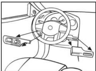
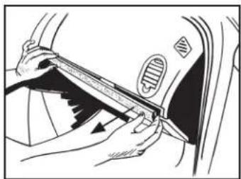
- Unclip and remove the wood grain/painted trim pieces from both sides of steering wheel. (Figure A)
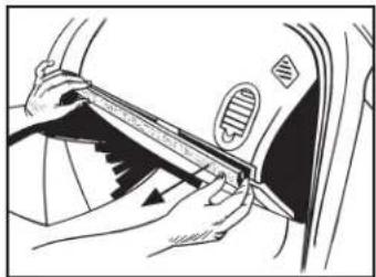
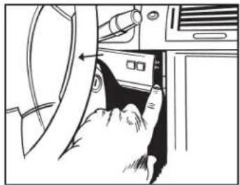
- Unclip and remove the side panel from the driver's side of the dash with the door open and remove (2) 7mm screws. (Figure B)
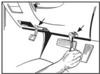
- Remove (2) 7mm screws from the bottom edge of the panel below the steering wheel. Unclip the panel and let hang (not necessary to completely remove the panel). (Figure C)
- Unclip and remove the wood grain/painted trim pieces from above glove box.(Figure D)
Continued on the next page
natural_image
Diagram of a car dashboard and steering wheel assembly (no text or labels)(Figure A) (Figure C)
natural_image
Illustration of a hand using a tool to adjust or install a car's seat, with arrows indicating the mechanism (no text or symbols present)
natural_image
Line drawing of a person using a tool to adjust or install a car door panel (no text or symbols visible)(Figure B) (Figure D)
natural_image
Line drawing of a car interior showing hand positioning and valve mechanism (no text or symbols)Dash Disassembly
Chevrolet Malibu/Malibu Maxx 2004-2007 Malibu Classic 2008
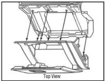
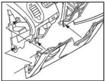
- Unclip and remove the side panel from the driver's side of the dash with the door open, and remove (2) 7mm screws from behind the panel. (Figure E)
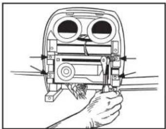
- Remove (2) 7mm screws from the bottom of the glove box. Open the box and squeeze the sides together to open it further, and then remove the remaining (4) 7mm screws. Unclip the black vent cover under the glove box, then unclip and remove entire glove box assembly. (Figure F)
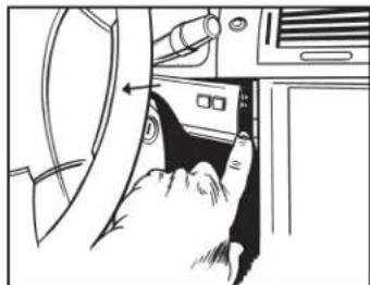
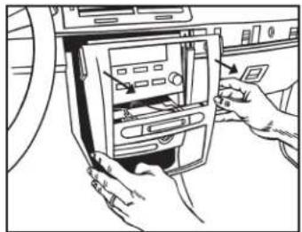
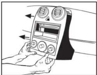
- Unclip and remove the trim panel surrounding the radio and climate controls. (Figure G)
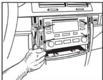
- Remove (4) 7mm screws from the radio, and (2) 7mm screws from the climate control to remove the radio. (Figure H)
Continue to kit assembly
natural_image
Line drawing of a hand holding a tool near a mechanical component (no text or symbols)(Figure E)

natural_image
Technical line drawing of a car interior showing hand positioning and valve mechanism (no text or symbols)(Figure G)

natural_image
Illustration of a hand using a tool to adjust or install a mechanical component (no text or symbols visible)(Figure F) (Figure H)
natural_image
Diagram of a mechanical device with arrows indicating motion or force direction (no text or symbols present)
99-3303
Dash Disassembly
Pontiac G6 2005-2008/G6 (5th digit of VIN must be a J, K, or L) 2009
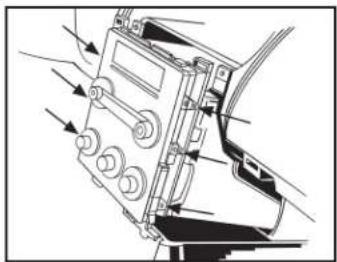
- Open the glove box and remove (6) 7mm screws from the outer the edge, and then unclip and remove. (Figure A)
- Remove (4) 7mm screws from the panel below the steering column, and then unclip and remove. (Figure B)
- Unclip and remove the center panel surrounding the radio and climate controls, and then remove. (Figure C)
- Remove (4) 7mm screws securing the radio, and then remove. (Figure D)
Continue to kit assembly
natural_image
Technical line drawing of a mechanical assembly with no visible text or symbols(Figure A)

natural_image
Illustration of a hand holding a device with arrows indicating left-hand orientation (no text or symbols)(Figure C)
natural_image
Technical line drawing of a mechanical assembly with no visible text or symbols(Figure B) (Figure D)

natural_image
Illustration of a hand operating a device with adjustment knobs and a circular component (no text or symbols visible)Dash Disassembly
Chevrolet Cobalt (with OnStar) 2005-2006
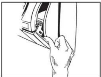
- Unclip and remove the trim panel from above the glove box. (Figure A)
- Unclip the upper edge of the panel below the steering column and let hang.
Note: It is not necessary to remove the panel. (Figure B)
- Unclip and remove the small trim panel to the right of the ignition switch. (Figure C)
- Unclip and remove the trim panel surrounding the radio and climate controls. (Figure D)
- Remove (4) 7mm screws securing the radio and then remove. (Figure E)
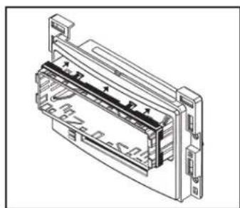
- Cut and remove top mounting tabs on each side of the radio housing. (Figure F)
Continue to kit assembly

natural_image
Line drawing of hands inserting a fan into a car's air vent (no text or symbols)(Figure A)
natural_image
Line drawing of a hand inserting a device into a folder (no text or symbols visible)(Figure C)
natural_image
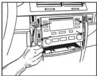
Line drawing of a hand inserting a CD into a car infotainment panel (no text or symbols visible)(Figure E)

natural_image
Line drawing of a car interior showing steering wheel, dashboard, and steering wheel (no text or symbols)(Figure B) (Figure D)
natural_image
Line drawing of hands installing or adjusting a device into a car air vent (no text or symbols visible)
text_image
Cut the two top holes off(Figure F)
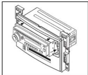
Kit Assembly
DIN radio provision with driver information center (DIC)
- Remove the metal DIN sleeve from the aftermarket radio.
- Slide the sleeve in the radio housing and secure by bending the metal locking tabs down.
Note: A DIN spacer has been provided for applications where depth is an issue. If using the spacer, attach it to the sleeve before sliding it into the radio housing. (Figure A)
- Slide the radio back into the sleeve until it clicks in. (Figure B)
- Locate the factory wiring harness and antenna connector in the dash and complete all necessary connections to the radio. Metra recommends using the proper mating adapter from Metra or AXXESS. Re-connect the negative battery terminal and test the radio for proper operation.)
- Reassemble the dash in reverse order of disassembly.
Continue to final assembly
natural_image
Technical line drawing of a mechanical or electronic component with no visible text or symbols(Figure A)

natural_image
Technical line drawing of a mechanical device with no visible text or symbols(Figure B)
ISO DIN radio provision with driver information center (DIC)
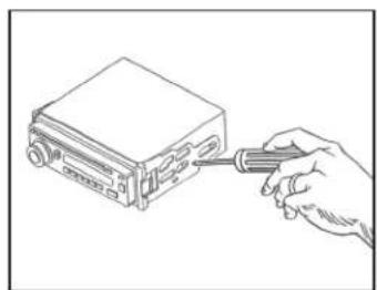
- Remove the metal DIN sleeve and trim ring from the aftermarket radio.
- Secure the ISO brackets to the radio using the screws supplied with the radio. (Figure A)
- Slide the radio into the radio housing until it snaps into place. (Figure B)
- Snap the ISO trim plate onto the front of the radio housing. (Figure B)
- Locate the factory wiring harness and antenna connector in the dash and complete all necessary connections to the radio. Metra recommends using the proper mating adapter from Metra or AXXESS. Re-connect the negative battery terminal and test the radio for proper operation.)
- Reassemble the dash in reverse order of disassembly.
Continue to final assembly
natural_image
Line drawing of a hand inserting a screwdriver into a computer drive (no text or symbols)(Figure A)

text_image
Right Side Clip(Figure B)
Final Assembly
Connections to be made Installing the 99-3303
From the 99-3303 wiring harness to the aftermarket radio:
- Connect the Black wire to the ground wire.
- Connect the Yellow wire to the battery wire.
- Connect the Red wire to the accessory wire.
- Connect the Blue/White wire to the amp turn-on wire.
Note: This wire must be connected for the interface to function.
- Connect the White wire to the left front positive speaker output.
- Connect the White/Black wire to the left front negative speaker output.
- Connect the Gray wire to the right front positive speaker output.
- Connect the Gray/Black wire to the right front negative speaker output.
- Connect the Green wire to the left rear positive speaker output.
- Connect the Green/Black wire to the left rear negative speaker output.
- Connect the Purple wire to the right rear positive speaker output.
- Connect the Purple/Black wire to the right rear negative speaker output.
- Connect the 99-3303 wiring harness into the connectors on the back of the radio housing, and then into the vehicle.
Note: For models without OnStar, disregard the 12-pin connector. - With all connections completed, reconnect the negative battery terminal.
Attention: If the 99-3303 ever loses power, the following step will have to be performed again. - Initialize the interface by turning the ignition on for 30 seconds, then turn the ignition back off, then back on again.

Installation instructions for part 99-3303

Operation of the 99-3303
Setting and adjustment mode
For the adjustment of contrast, brightness, backlighting, button backlight color, and OnStar volume.
Entering the settings and adjustments mode
Press the "INFO" and "MENU" buttons simultaneously. When the settings and adjustments mode is entered, the LCD will display, "Func Sel MENU".
Selecting a function to update
Use the "MENU" button to select a function. The LCD will display the selected function. (See Legend)
Updating a function
Use the "INFO" and "ENTER" buttons to adjust the function selected and displayed on the LCD. (See Legend)
Note: When OnStar is activated, the "INFO" and "ENTER" buttons can be used to adjust the OnStar volume without first entering the settings and adjustments mode.
Exiting the settings and adjustments mode
The settings and adjustments mode will exit if no buttons are pressed for 10 seconds.
| Function | LCD Display | Description of Operation |
| LCD Contrast | Contrast INF/ENT | INFO increases LCD contrastENTER decreases LCD contrast |
| LCD Brightness | Bright INF/ENT | INFO increases LCD brightnessENTER decreases LCD brightness |
| OnStar Volume | OnSt Vol INF/ENT | INFO increases OnStar VolumeENTER decreases OnStar Volume |
| Button Backlighting Color | Button Color ENT | ENTER changes the button backlighting between Amber and Green |
| Clock Set | Set Time INF/ENT | INFO changes hour(s)ENTER changes minute(s) |
IMPORTANT
If you are having difficulties with the installation of this product, please call our Tech Support line at 1-800-253-TECH. Before doing so, look over the instructions a second time, and make sure the installation was performed exactly as the instructions are stated. Please have the vehicle apart and ready to perform troubleshooting steps before calling.

KNOWLEDGE IS POWER
Enhance your installation and fabrication skills by enrolling in the most recognized and respected mobile electronics school in our industry. Log onto www.installerinstitute.com or call 800-354-6782 for more information and take steps toward a better tomorrow.

Metra recommends MECP certified technicians
Chevrolet/Pontiac DIC Interfase 2004-2009 99-3303
CARACTERÍSTICAS DEL KIT
natural_image
Front panel of a CD-ROM drive showing front latches and control buttons (no readable text or symbols)COMPONENTES DEL KIT
natural_image
Diagram of a car interior showing steering wheel, dashboard, and steering wheel (no text or labels)(Figura A) (Figura C)

natural_image
Illustration of a hand using a tool to adjust or install a car's seat frame (no text or symbols visible)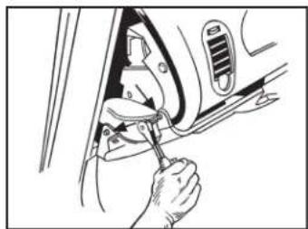
natural_image
Illustration of a person using a tool to adjust or install a car interior panel (no text or symbols visible)(Figura B) (Figura D)
natural_image
Line drawing of a car interior showing hand positioning and tool interacting with the wheel (no text or symbols)Desmontaje tablero
Chevrolet Malibu/Malibu Maxx 2004-2007 Malibu Classic 2008
natural_image
Line drawing of a hand holding a tool near a mechanical component (no text or symbols)(Figura E)

natural_image
Technical line drawing of a car interior showing hand positioning and valve mechanism (no text or symbols)(Figura G)

natural_image
Illustration of a hand using a tool to adjust or install a mechanical component (no text or symbols visible)(Figura F) (Figura H)

natural_image
Diagram of a mechanical device with arrows indicating motion or force direction (no text or symbols present)
99-3303
Desmontaje tablero
natural_image
Technical line drawing of a mechanical assembly with no visible text or symbols(Figura A)
natural_image
Illustration of a hand holding a device with arrows indicating left-hand orientation (no text or symbols)(Figura C)

natural_image
Technical line drawing of a mechanical assembly with no visible text or symbols(Figura B) (Figura D)
natural_image
Illustration of a hand operating a device with adjustment knobs and a circular component (no text or symbols visible)Desmontaje tablero
natural_image
Line drawing of hands inserting a fan into a car's air vent (no text or symbols)(Figura A)
natural_image
Line drawing of a hand inserting a component into a vehicle's door panel (no text or symbols)(Figura C)
natural_image
Line drawing of a hand inserting a CD into a car infotainment panel (no text or symbols visible)(Figura E)

natural_image
Line drawing of a car interior showing steering wheel, dashboard, and steering wheel (no text or symbols)(Figura B) (Figura D)

natural_image
Line drawing of hands inserting a device into a car's air vent (no text or symbols visible)
natural_image
Technical line drawing of a mechanical or electronic component with no visible text or symbols(Figura A)
natural_image
Technical line drawing of a mechanical device with no visible text or symbols(Figura B)
natural_image
Line drawing of a hand inserting a screwdriver into a device (no text or symbols)(Figura A)
