VRFBM-77EF - Fridge CRUX - Free user manual and instructions
Find the device manual for free VRFBM-77EF CRUX in PDF.

User questions about VRFBM-77EF CRUX
0 question about this device. Answer the ones you know or ask your own.
Ask a new question about this device
Download the instructions for your Fridge in PDF format for free! Find your manual VRFBM-77EF - CRUX and take your electronic device back in hand. On this page are published all the documents necessary for the use of your device. VRFBM-77EF by CRUX.
USER MANUAL VRFBM-77EF CRUX
- Plug and Play Installation
• Media Controller with controls by factory infotainment (iDrive) - Rear-view camera input
- Front camera input
- Front camera input can also be used as an Auxiliary Video Input (Crux part# AUX-ABMP1, Fiber Optic Auxiliary Audio Input Interface, may be required to create an Auxiliary Audio Input). (Sold separately)
- Manual switching to rear-view camera (only for vehicles with PDC button)
- Manual return from rear-view and front camera (cancellation of automatic switching)
- 2 trigger outputs (+12V max. 1A), separately adjustable switching events (CAN, ACC, camera, reverse gear)
• Picture-in-picture mode combining aftermarket rear-view and front camera picture(s) with factory parking sensor graphics - Compatible with all factory video accessories (e.g. rear-view camera, Top-View Camera System)
PARTS INCLUDED:
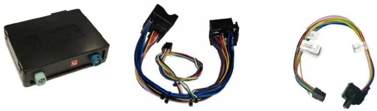
VRFBM-77EF Module BM-77EF Harness E-Series Power/CAN Harness
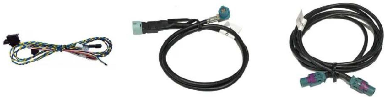
F-Series Power/CAN2 Harness LVDS1 Cable (to vehicle) LVDS2 Cable (to radio)
INSTALLATION DIAGRAM:

flowchart
graph TD
    A["BM-77EF Module"] -->|LVDS2 Cable| B["Back of Headunit"]
    A -->|LVDS1 Cable| C["4-Pin HSD Female LVDS Vehicle Harness"]
    B --> D["Female Quadlock Vehicle Harness"]
    C --> E["Front Camera (Not Included)"]
    C --> F["Rear-View Camera (Not Included)"]
    C --> G["DVD Player (Not Included)"]
    C --> H["Portable Video Player (Not Included)"]
DIP SWITCH SETTINGS:
| VEHICLE / SCREEN SIZE DIP 1 DIP 2 | DIP 3 ____ | ____ | ____ |
| CIC-E (E-Series) / 6.5” OFF OFF No Function | |||
| CIC-E (E-Series) / 8.8” OFF ON No Function | |||
| CIC-F (F-Series) / 7” ON OFF No Function | |||
| CIC-F (F- Series) / 10.2” ON ON No Function | |||
You have to execute a power reset of the interface after each change of DIP switch settings! NOTES:
- The Interface is installed behind the headunit and needs a constant +12V power source.
- Use the appropriate Power/CAN harness for the application (E or F Series).
INSTALLATION INSTRUCTIONS:
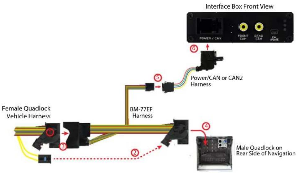
Connecting the VRFBM-77EF harness
text_image
Interface Box Front View POWER / CAN FRONT CAN READ CAN FW BONE ⑥ Power/CAN or CAN2 Harness ⑤ Female Quadlock Vehicle Harness BM-77EF Harness ④ Male Quadlock on Rear Side of Navigation1 Remove the female Quadlock connector of the vehicle harness from the rear of the headunit.
2 Remove optical leads from the female Quadlock connector of the vehicle harness and insert them into the female Quadlock connector of BM-77EF harness at the same position.
3 Connect female Quadlock connector of vehicle harness to the male Quadlock connector of BM-77EF harness.
4 Connect female Quadlock connector of BM-77EF to the male Quadlock connector of the headunit.
5 Connect female 8 pin molex connector of the BM-77EF harness to the male 8 pin molex connector of the Power/CAN or Power/CAN2 harness.
6 Connect the female 12pin Power/CAN or Power/CAN2 harness to the VRFBM-77EF module.
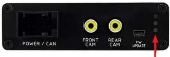
LEDs on the VRFBM-77EF Module
text_image
POWER / CAN FRONT CAM REAR CAM FW UPDATEBLUE = Valid Input Source
GREEN = OK
RED = Power
LVDS Connection
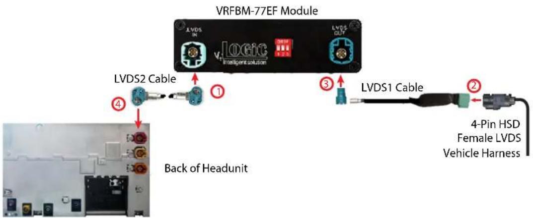
text_image
VRFBM-77EF Module LVDS IN vLogic Intelligent solution LVDS OUT LVDS2 Cable ① ③ LVDS1 Cable ② 4-Pin HSD Female LVDS Vehicle Harness Back of Headunit1 Connect the female 4pin HSD LVDS connector of the LVDS cable to the male 4pin HSD LVDS connector (LVDS-IN) on the rear of the VRFBM-77EF module.
2 Remove the grey female 4pin HSD LVDS connector of the vehicle harness at the back of the head unit and connect it to the male 4pin HSD LVDS of the LVDS1 cable.
3 Connect the female 4pin HSD LVDS connector of the LVDS1 cable to the male 4pin HSD LVDS connector (LVDS-OUT) on the rear of the VRFBM-77EF module.
4 Connect the female 4pin HSD LVDS connector of the LVDS cable to the grey male 4pin HSD LVDS connector on the rear of the headunit.
Connection to iDrive on F-Series Vehicles
1 Remove the iDrive from the center console and unplug the existing flat female 10pin or 4pin cable connector.
2 Remove Pin 3 (Green/Orange) CAN-High and Pin 4 (Green) CAN-Low from the female cable connector.
3 Plug Yellow (CAN High) and Blue (CAN Low) wires (with terminals) of the Power/CAN harness into Pin 3 (CAN-High) and Pin 4 (CAN-Low) of the female cable connector.
Plug the Green/Orange wire (CAN-High) and Green cable (CAN-Low) of the vehicle harness into Pin 1 and Pin 2, respectively, of the included female 2 pin AMP connector.
5 Connect female 2 pin AMP connector to 2pin AMP connector (Yellow/Black and Blue/Black cable) of the Power/CAN harness.

text_image
VRFBM-77EF Interface POWER CAN F Series CAN2 Harness CAN-Low (Blue) CAN-High (Yellow) Female 10-Pin iDrive Connector CAN-Low Pin 4 (Green) CAN-High Pin 3 (Green/Orange)Connection to the Aftermarket Front Camera

text_image
POWER / CAN FRONT CAM REAR CAM Pin UPDATE Power/CAN Harness +12V Camera Power (Pink) Power Out 1 (max 1A) Front Camera (Not Included)Connect the video RCA of the aftermarket front camera to the female RCA connector "FRONT CAM" of the VRFBM-77EF module.
The PINK wire of the Power/CAN harness can be used for +12V power supply (max. 1A) of the aftermarket front camera. Configure in the OSD-menu "MISC", menu item "POWER OUT 1" the designated power supply (see chapter "Configurable Switching Outputs" on page 8).
text_image
V OGIC INPUTS REVERSE LOGIC C-RGEAR+SPEED MISC POWER OUT 1 CAM OSD POWER OUT 2 CAM INFO FACTORY RESET EXIT BACKOSD Settings for Front Camera
Configure settings in the OSD menu's MISC and INPUTS if an aftermarket front camera will be used. See OSD Operation section for instructions on how to use the OSD Menu.
text_image
LOGIC INPUTS MISC OSD INFO EXIT REAR CAM ON FRONT CAM ON| OSD Menu | Menu Item Setting Description | ||
| INPUTS | FRONT CAM | OFF | No Front camera connected |
| ON | Switches to front camera if parking process is enabled and reverse gear is released | ||
| REVERSE LOGIC | Intelligent | For vehicles with PDC button. Enabled while parking process and up to 12 mph or together with PDC if available | |
| GearOnly | For vehicles without PDC button. Enabled while parking process and up to 12 mph | ||
| MISC OEM P | DC CAR | Horizontal | Vehicles with horizontal OEM PDC display |
| Vertical | Vehicles with vertical OEM PDC display | ||
Note: You can deactivate the enabled parking process by pressing the iDrive or by enabling other modes (e.g. radio). After deactivation you cannot enable the parking process again until the vehicle is driving faster than 12 mph and the ignition is switched off and on, or the PDC be disabled and enabled again.
Connection to the Aftermarket Backup Camera
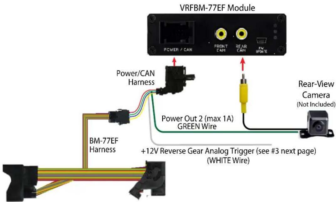
text_image
VRFBM-77EF Module POWER / CAN FRONT CAM REAR CAM FV UPDATE Power/CAN Harness Power Out 2 (max 1A) GREEN Wire +12V Reverse Gear Analog Trigger (see #3 next page) (WHITE Wire) Rear-View Camera (Not Included) BM-77EF Harness1 Connect the video RCA of the aftermarket rear-view camera to the female RCA connector "REAR CAM" of the VRFBM-77F interface box.
The green wire of the BM-77EF harness can be used for +12V power supply (max. 1A) of the aftermarket rear-view camera. Configure in the OSD-menu "MISC", menu item "POWER OUT 2" the designated electric power supply (see chapter "Configurable Switching Outputs").
On some vehicles the reverse light signal does not exist on the CAN-Bus. Connect the white wire of the BM-77EF harness to the reverse light signal (+12V of reverse light) if the system does not switch to the rear-view camera automatically after the described OSD-setup.
| V4 OGIC | ||
| IMAGE | VERSION | 1.6 0.0.45 |
| INPUTS | POWEROUT1 | CAM |
| OSD | POWEROUT2 | RearCam |
| MISC | OEMPDC CAR | Horizontal |
| VIM | ON | |
| FACTORY RESET | ||
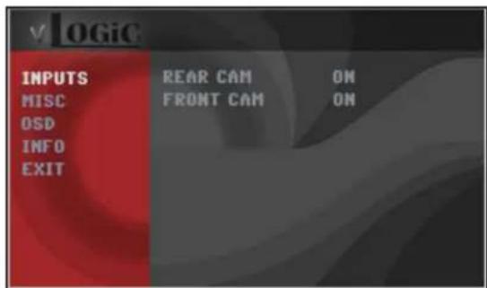
OSD Settings for Backup Camera
Configure settings in the OSD menu's MISC and INPUTS if an aftermarket front camera will be used. See OSD Operation section for instructions on how to use the OSD Menu.

text_image
v4 OGIC IMAGE INPUTS OSD MISC REARCAM ON FRONTCAM ON REVERSE LOGIC Gear only| OSD Menu | Menu Item Setting Description | ||
| INPUTS | REAR CAM | OFF | No Rear camera connected |
| ON | Switches to Rear camera if reverse gear is engaged and/or PDC display is displayed | ||
| OEM | If a factory rear-view camera is connected. Interface turns off, if PDC or reverse gear is enabled and it displays factory rear-view camera and/or PDC-display | ||
| REVERSE LOGIC | Intelligent | For vehicles with PDC button. Enabled while parking process and up to 12 mph or together with PDC if available | |
| GearOnly | For vehicles without PDC button. Enabled while parking process and up to 12 mph | ||
| MISC OEM PDC CAR | Horizontal | Vehicles with horizontal OEM PDC display | |
| Vertical | Vehicles with vertical OEM PDC display | ||
Note: You can deactivate the enabled parking process by pressing the iDrive or by enabling other modes (e.g. radio). After deactivation you cannot enable the parking process again until the vehicle is driving faster than 12 mph and the ignition is switched off and on, or the PDC be disabled and enabled again.
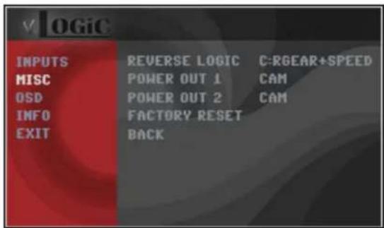
Configurable Trigger Outputs
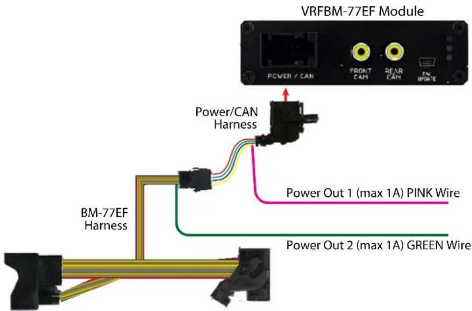
text_image
VRFBM-77EF Module POWER / CAN FRONT CAM REAR CAM FM UPDATE Power/CAN Harness Power Out 1 (max 1A) PINK Wire BM-77EF Harness Power Out 2 (max 1A) GREEN WireYou can configure the both +12V trigger outputs separately.
PINK Wire = POWER OUT 1
GREEN Wire = POWER OUT 2
text_image
v OGIC IMAGE VERSION 1.6 0.0,45 INPUTS POWEROUT1 CAN OSD POWEROUT2 RearCam MISC DEMPDC CAR Horizontal VIM ON FACTORY RESET| OSD Menu | Menu Item | Setting | Description |
| INPUTS | POWER OUT 1 (PINK Wire) | CAN | +12V when the interface is on (Red LED on) |
| Ignition | +12V when ignition is on | ||
| Rear Cam | +12V when the rear-view camera input is activated | ||
| POWER OUT 2 (GREEN Wire) | Reverse Gear | +12V when reverse gear is engaged | |
| OFF | Trigger output deactivated |
Display Settings
Picture Format
You can change the picture format by long press of the CD Button (BMW with 8-button iDrive) or by long press of the Menu Button (2-button iDrive in Mini) while in the respective video mode. The following options are available:
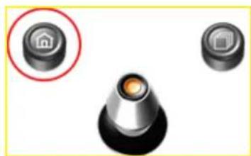
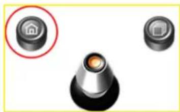
natural_image
Three industrial control knob components with a red circle highlighting a home button (no text or symbols)2 Button iDrive
8.8" and 10.2" 24:10 Ultrawide Screen:
- FULL = 24:10 interface full screen mode
- Zoom = 24:10 interface full screen mode zoom
- 16:9 = 16:9 interface picture central
- 4:3 = 4:3 interface picture central
• AV + LVDS = 16:9 interface picture on left side, factory picture on right side
• LVDS + AV = 16:9 factory picture on left side, interface picture on right side
6.5" and 7" 16:9 Screen:
• FULL = 16:9 interface full screen mode
• ZOOM = 16:9 interface full screen mode zoom
- 4:3 = 4:3 interface picture central
Note: The picture format will be retained for each AV source separately.

text_image
CD MENU TEL BAZRO NAV BACK OPTION8 Button iDrive
Picture Settings
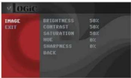
text_image
v LOGIC IMAGE EXIT BRIGHTNESS 50% CONTRAST 50% SATURATION 50% HUE 0% SHARPNESS 0% BACK- Brightness
- Contrast
- Saturation
Hue - Sharpness
OPERATION
OSD - On Screen Display
You can change the picture settings in the OSD Menu IMAGE
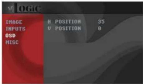
text_image
LOGIC IMAGE H POSITION 35 INPUTS U POSITION 0 OSD MISC
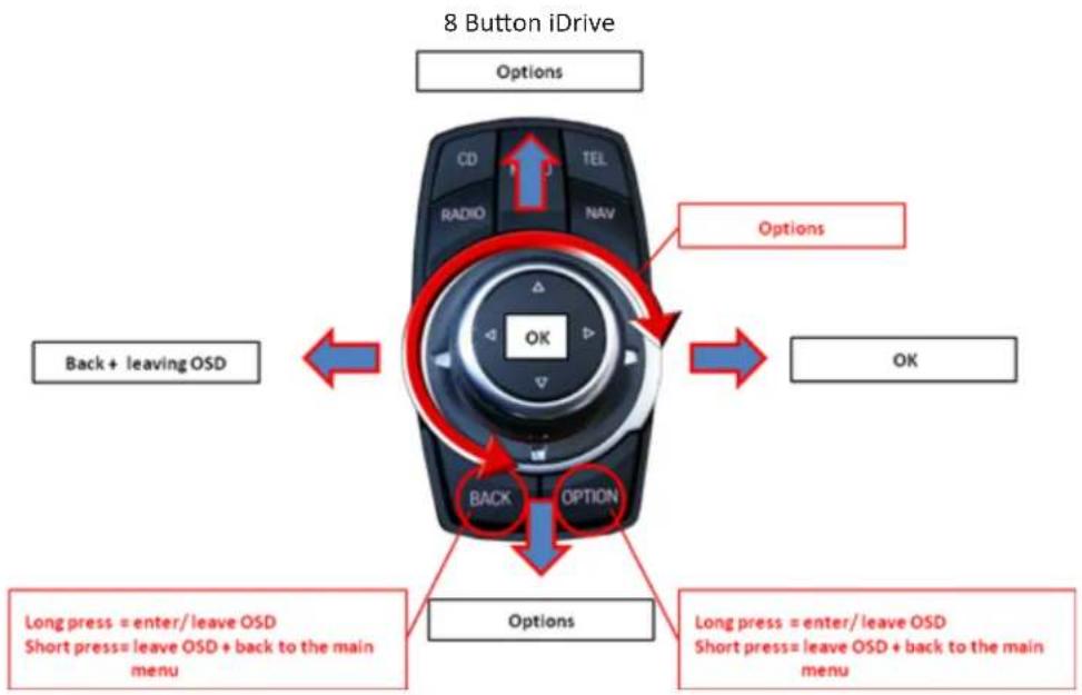
OSD Operation
You can control the OSD by using the iDrive.
flowchart
graph TD
    A["Back + leaving OSD"] --> B["Options"]
    C["Short press = leave OSD + back to the main menu"] --> D["Options"]
    E["Long press = enter/leave OSD"] --> F["Back"]
    G["Short press = leave OSD + back to the main menu"] --> H["Options"]
    I["Back"] --> J["OK"]
    K["Short press"] --> L["OK"]
    M["Long press"] --> N["Back"]
    O["Short press"] --> P["OK"]
    Q["Long press"] --> R["Back"]
    S["Short press"] --> T["OK"]
    U["Long press"] --> V["Back"]
    W["Short press"] --> X["OK"]
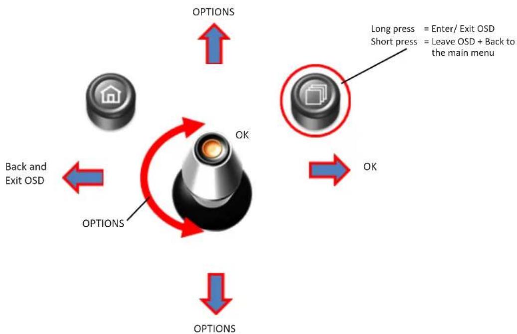
2 Button iDrive in Mini
flowchart
graph TD
    A["Home Icon"] -->|OPTIONS| B["Switch"]
    C["Back and Exit OSD"] -->|OPTIONS| B
    D["Short press"] -->|OPTIONS| B
    E["Long press"] -->|OPTIONS| B
    F["Leave OSD + Back to the main menu"] -->|OK| B
    G["OK"] --> B
Additional OSD Settings
The following are additional settings that can be set in the OSD Menu.

text_image
V OGiC IMAGE N POSITION 35 INPUTS U POSITION 8 OSD HISC
text_image
V OGiC INPUTS REVERSE LOGIC C:GEAR+SPEED MISC POWER OUT 1 CAM OSD POWER OUT 2 CAM INFO FACTORY RESET EXIT BACK| OSD Menu | Menu Item Setting Description | ||
| MISC | H POSITION | 0-xxx | Horizontal position of the OSD |
| V POSITION | 0-xxx Vertical position of the OSD | ||
| VERSION | X.XX.XX Displays the current SW-version | ||
| FACTORY RESET | Reset to Factory Settings | ||
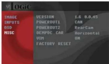
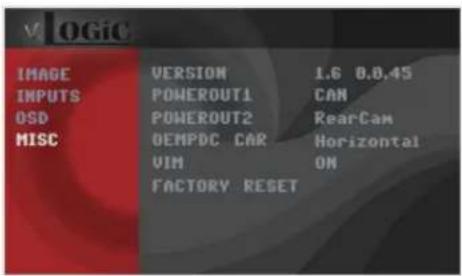
Video In Motion Function
Activate and deactivate the Video In Motion function in the OSD Menu
text_image
V OGIC IMAGE VERSION 1.6 8.0,45 INPUTS POWEROUT1 CAN OSD POWEROUT2 RearCam MISC OEMPDC CAR Horizontal VIM ON FACTORY RESET| OSD Menu | Menu Item Setting Description | ||
| MISC | VIM | ON | Activate Video In Motion |
| OFF Deactivate | Video In Motion | ||
NOTE: The Video-In-Motion function is permanently active without disturbing the navigation performance.
Selecting the VRFBM-77EF as Video Source

text_image
CD MENU TEI RADIO NAV BACK OPTION8 Button iDrive
natural_image
Close-up of three mechanical components: a black knob with a red circle highlighting a house-shaped component, and two others (no text or symbols visible)2 Button iDrive
A Long press of the CD Button or the Menu Button will select the interface as the current video source.
A Short press of the CD Button or the MENU Button will switch the video sources (cameras or other video source). Each short press will switch to the next enabled input. If all inputs are enabled the order is:
FRONT CAM → REAR CAM → ...
Inputs which are not enabled are skipped.
VEHICLE APPLICATIONS:
| 1 SERIES | 6 Series | ||
| 2007 - 2011 | 1 Series 3-door hatchback | 2011-Up | 6 Series |
| 2007 - 2013 | 1 Series 2-door Coupe (1M) | 2011-Up | 6 Series Convertible |
| 2004 - 2012 | 1 Series (5-door) | ||
| 2008 - Up | 1 Series Convertible | 7 Series | |
| 2008-Up | 7 Series | ||
| 2009-Up | 7 Series long wheel | ||
| 3 SERIES | |||
| 2005 - 2011 | 3 Series Sedan | ||
| 2005 - 2011 | 3 Series Wagon | X SERIES | |
| 2006 - 2013 | 3 Series Coupe | 2009 - Up | X1 Sports Vehicle |
| 2007 - Up | 3 Series Convertible | 2012-Up | X3 Sports Vehicle |
| 2005 - 2011 | 3 Series Sedan | 2007 - 2013 | X5 Sports Activity Vehicle |
| 2005 - 2011 | 3 Series Wagon | 2008 - 2011 | X6 Sports Activity Coupe |
| 2006 - 2013 | 3 Series Coupe | ||
| 2007 - Up | 3 Series Convertible | ||
5 SERIES
2011-Up 5 Series
2012-Up 5 Series Sports Wagon
Z SERIES
2009 - Up Z4 Roadster
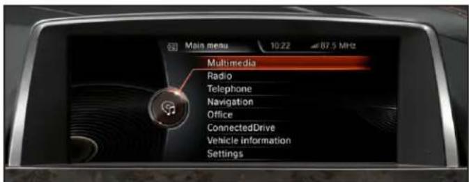
text_image
Main menu 10:22 87.5 MHz Multimedia Radio Telephone Navigation Office ConnectedDrive Vehicle information SettingsCIC Navigation Screen

12 of 12
rev.040119
Crux Interfacing Solutions • 21541 Nordhoff St., Unit C, Chatsworth, CA 91311
phone: (818) 609-9299 • fax: (818) 996-8188 • www.cruxinterfacing.com