
DKGM-48S - Audio Interface / Mounting Kit CRUX - Free user manual and instructions
Find the device manual for free DKGM-48S CRUX in PDF.


| Product Type | Audio Interface / Mounting Kit |
| Brand | CRUX |
| Model | DKGM-48S |
| Category | Car Audio Accessories |
| Compatible Vehicles | Select GM models (2000-2010) |
| Dimensions (L x W x H) | 4.7 x 3.2 x 1.1 inches |
| Weight | 0.5 lbs |
| Power Input | 12V DC (vehicle battery) |
| Audio Input | RCA, Speaker-level |
| Audio Output | RCA, Optical (if applicable) |
| Mounting Type | Double DIN / Single DIN with pocket |
| Material | ABS Plastic, Metal brackets |
| Color | Black |
| Installation | Plug-and-play with included harness |
| Special Features | Retains factory chimes, steering wheel controls, OnStar |
| Warranty | 1-year limited |
Frequently Asked Questions - DKGM-48S CRUX
User questions about DKGM-48S CRUX
0 question about this device. Answer the ones you know or ask your own.
Ask a new question about this device
Download the instructions for your Audio Interface / Mounting Kit in PDF format for free! Find your manual DKGM-48S - CRUX and take your electronic device back in hand. On this page are published all the documents necessary for the use of your device. DKGM-48S by CRUX.
USER MANUAL DKGM-48S CRUX
- Retains factory features in select GM Class II Data Bus vehicles while functioning with an aftermarket radio.
- Pre-programmed to retain factory Steering Wheel Controls.
- Voice Recognition Command from factory SWC.
- Supports Bose, Y-91 and non-amplified audio systems.
- Retains chime functions.
- Built-in chime volume adjustment.
- Single DIN Dash Kit included.
- EIA color coded wiring for easy installation.
PARTS INCLUDED:
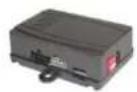
GM-48S Module
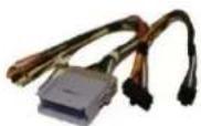
GM-48S Harness (GM-C2)

SWC Cables

Single DIN Dash Kit
INSTALLATION DIAGRAM:

flowchart
graph TD
    A["TO FACTORY HARNESS"] --> B["24-Pin Connector"]
    B --> C["16-Pin Black Connector"]
    C --> D["CRUX"]
    D --> E["Chime volume adjustment"]
    E --> F["Aftermarket RADIO SELECTOR (See Chart)"]
    F --> G["3.5MM SWC CABLES (Option A or B)"]
    G --> H["Cap or insulate if not being used"]
    H --> I["Insulate with tape if not being used"]
    I --> J["Blue/YELLOW"]
    J --> K["Option A"]
    style A fill:#f9f,stroke:#333
    style B fill:#ccf,stroke:#333
    style C fill:#cfc,stroke:#333
    style D fill:#fcc,stroke:#333
    style E fill:#cff,stroke:#333
    style F fill:#ffc,stroke:#333
    style G fill:#fcc,stroke:#333
    style H fill:#ffc,stroke:#333
    style I fill:#cfc,stroke:#333
    style J fill:#fcc,stroke:#333
    style K fill:#ffc,stroke:#333
NOTES:
- The Front and Rear fading are not retained on Y-91 Bose System.
- Chime includes: seat belt, check engine, key in ignition, low fuel, low oil and lights on.
DIP SWITCH SETTINGS:
SETTING THE AFTERMARKET RADIO BRAND
With the key in the off position, set the DIP switches to the corresponding radio listed below. See page 8 for SWC button functions.
| RADIO BRAND: | DIP#: | 1 | 2 | 3 |
| Atoto, Dual, Fahrenheit, Jensen | OFF | ON | ON | |
| Pioneer, Power Acoustik, Soundstream | OFF | ON | ON | |
| Blaupunkt, Most off-brand Radio | OFF | ON | ON | |
| Alpine | OFF | OFF | OFF | |
| Clarion | ON | ON | OFF | |
| Kenwood | ON | ON | ON | |
| JVC | ON | OFF | ON | |
| Boss, Old Sony | ON | OFF | OFF | |
| New Sony | OFF | ON | OFF | |
SWC MODULE DIP SWITCH

1 2 3
NOTE: For Atoto, Blaupunkt, Dual, Farenheit, Power Acoustik, Soundstream, and most off-brand radios, check the aftermarket radio's manual to see if the SWC buttons need to be programmed.
3.5MM SWC CABLE
The SWRGM-48S Module allows for both types of connections:
OPTION A is used for ALPINE, CLARION, JVC, and KENWOOD units (Blue/Yellow wire is attached)
OPTION B is used for ATOTO, BOSS, DUAL, FAHRENHEIT, JENSEN, PIONEER, POWER ACOUSTIK, SONY, SOUND STREAM and other Off-Brand headunits.
NOTE: Cap or insulate the 3.5mm plug or Blue/Yellow wire if not being used.
SELECTING THE AUDIO SYSTEM:
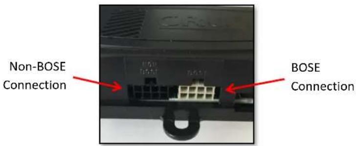
If the vehicle is equipped with a Bose system, the DKGM-48S has a built-in Bose adaptor that allows the proper audio input gain from the aftermarket radio to the Bose amplifier. To use this feature, plug in the male 8-pin connector on the harness to the GRAY female 8-pin connector on the GM-48S module. The module is also labeled "Bose" and "Non Bose" to avoid confusion. (see picture below)
If the vehicle is NOT equipped with a Bose system, plug in the male 8-pin connector to the BLACK female 8-pin on the GM-48S module.
CHIME VOLUME ADJUSTMENT:
The DKGM-48S has a potentiometer to adjust the chime volume. It is set at half way by default. To adjust the volume, simply use a suitable screw driver and turn the potentiometer clockwise to increase the volume and counter-clockwise to decrease the volume.

DASH KIT INSTALLATION:
Please make sure that you have all the parts shown below.

natural_image
Technical line drawing of a mechanical assembly with no visible text or symbols2001-2005 PONTIAC GRAND AM
DASH DISASSEMBLY INSTRUCTIONS
- Pry out trim bezel with a panel removal tool, disconnect harness and remove.
- Remove 3 (three) screws, remove antenna lead and harnesses.
- Remove the radio.
DIN MOUNT INSTALLATION
- Insert DIN sleeve from your new radio into the opening of the installation kit.
- Depress the tabs from the inside of sleeves to secure sleeves to the installation kit.

natural_image
Line drawing of a rectangular device with two horizontal panels, no text or symbols present2003-2006 CADILLAC ESCALADE
2003-2006 CHEVROLET AVALANCHE
2003-2006 CHEVROLET SILVERADO
2007 CHEVROLET SILVERADO (CLASSIC)
2003-2006 CHEVROLET SUBURBAN
2003-2006 GMC SIERRA
2003-2006 GMC YUKON/DENALI/XL
DASH DISASSEMBLY INSTRUCTIONS
- Place key into the ignition, turn the key to the "ON" position.
- Shift into first gear.
- Starting from the bottom, carefully pry the trim bezel from around the radio.
- Remove 3 (three) bolts, remove antenna lead and harnesses.
- Remove the radio.
DIN MOUNT INSTALLATION
- Insert DIN sleeve from your new radio into the opening of the installation kit.
- Depress the tabs from the inside of sleeves to secure sleeves to the installation kit.

natural_image
Technical line drawing of a rectangular device with two panels and ports (no text or symbols)2000-2005 CHEVROLET CAVALIER
2000-2005 PONTIAC SUNFIRE
DASH DISASSEMBLY INSTRUCTIONS
- Open the glove box, and remove 5 (five) screws.
- Remove side panels from both the driver and passenger side.
- Remove 1 (one) screw from each side.
- Remove 1 (one) screw from the top center of the air vent.
- Remove the dash bezel.
- Remove the 3 (three) screws holding the radio, remove antenna lead and harnesses.
- Remove the radio.
DIN MOUNT INSTALLATION
- Insert DIN sleeve from your new radio into the opening of the installation kit.
- Depress the tabs from the inside of sleeves to secure sleeves to the installation kit.

natural_image
Technical line drawing of a rectangular device with internal components and connectors (no text or symbols)2004-2006 CHEVROLET COLORADO
2004 CHEVROLET EXPRESS
2004-2006 GMC CANYON
2003-2004 GMC SAVANA
DASH DISASSEMBLY INSTRUCTIONS
- Starting from the bottom, carefully pry the trim bezel from around the radio.
- Remove 3 (three) bolts, remove antenna lead and harnesses.
- Remove the radio.
DIN MOUNT INSTALLATION
- Insert DIN sleeve from your new radio into the opening of the installation kit.
- Depress the tabs from the inside of sleeves to secure sleeves to the installation kit.

natural_image
Technical line drawing of a rectangular device with two internal compartments and ports (no text or symbols)2000-2005 CHEVROLET IMPALA
DASH DISASSEMBLY INSTRUCTIONS
- Remove 2 (two) screws from above the dash board.
- Remove the fuse panel plate and remove 1 (one) screw from the rear.
- Remove passenger fuse plate and remove 1 (one) screw from the rear.
- Using a panel removal tool, drop the underdash cover and remove 2 (two) screw from the rear.
- Remove 1 (one) screw from the left side trim, tilt steering wheel column down, and pry off trim bezel.
-
Remove 3 (three) screws, remove antenna lead and harnesses.
-
Remove the radio.
DIN MOUNT INSTALLATION
- Insert DIN sleeve from your new radio into the opening of the installation kit.
- Depress the tabs from the inside of sleeves to secure sleeves to the installation kit.

natural_image
Simple line drawing of a rectangular device with two horizontal panels and mounting feet (no text or symbols)2000-2005 CHEVROLET MONTE CARLO
DASH DISASSEMBLY INSTRUCTIONS
- Remove 1 (one) screw from the glove box.
- Remove the ignition switch collar with a flat blade.
- Remove 2 (two) screws from under the steering wheel column panel, and remove cover.
- Remove fuse access plate and 2 (two) screw from the rear.
- Tilt steering wheel column all the way down, and remove trim bezel.
- Disconnect any harnesses and remove bezel.
- Remove the radio.
DIN MOUNT INSTALLATION
- Insert DIN sleeve from your new radio into the opening of the installation kit.
- Depress the tabs from the inside of sleeves to secure sleeves to the installation kit.

natural_image
Pure technical line drawing of a rectangular device with internal components and mounting holes (no text or symbols)2002-2004 CHEVROLET S-10
DASH DISASSEMBLY INSTRUCTIONS
- Place key into the ignition, turn the key to the "ON" position.
- Shift into first gear.
- Remove 1 (one) screw from above the dash panel.
- Remove 5 (five) screws from below the dash pane, and remove the pane.
- Remove 2 (two) screws from the bottom of the trim bezel, and pry out.
NOTE: When removing the bezel, use extreme caution not to break the hazard switch. - Remove 3 (three) screw, remove antenna leads and harnesses.
- Remove the radio.
DIN MOUNT INSTALLATION
- Insert DIN sleeve from your new radio into the opening of the installation kit.
- Depress the tabs from the inside of sleeves to secure sleeves to the installation kit.

natural_image
Technical line drawing of a device rear panel with buttons and connectors (no text or symbols)2003-2006 CHEVROLET SSR
DASH DISASSEMBLY INSTRUCTIONS
- Remove the aluminum trim panel that separate the dash, using a panel removal tool.
- Remove 6 (six) screws from the radio dash panel.
- Remove the dash pulling outwards.
NOTE: Use extreme caution when near passenger side air bag. Bend the sides of the passenger air bag cover to release the right side of the dash. - Remove 3 (three) screws, remove antenna lead and harnesses.
- Remove the radio.
DIN MOUNT INSTALLATION
- Insert DIN sleeve from your new radio into the opening of the installation kit.
- Depress the tabs from the inside of sleeves to secure sleeves to the installation kit.
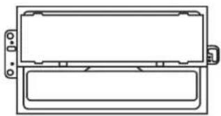
natural_image
Simple line drawing of a rectangular device with two horizontal panels and a handle (no text or symbols)2003-2006 CHEVROLET TRAILBLAZER
DASH DISASSEMBLY INSTRUCTIONS
- Remove 2 (two) screws from above the dash panel.
- Remove 1 (one) screw from below the AC controls.
- Remove 2 (two) screws from the lower dash panel above the brake panel.
- Pry out bezel, disconnect harness and remove.
- Remove 2 (two) screws, remove antenna lead and harnesses.
- Remove the radio.
DIN MOUNT INSTALLATION
- Insert DIN sleeve from your new radio into the opening of the installation kit.
- Depress the tabs from the inside of sleeves to secure sleeves to the installation kit.

natural_image
Technical line drawing of a rectangular electronic device with ports and connectors (no text or symbols)2000-2005 CHEVROLET VENTURE
2000-2004 OLDSMOBILE SILHOUETTE
2000-2006 PONTIAC MONTANA
DASH DISASSEMBLY INSTRUCTIONS
- Remove ashtray and remove 2 (two) screws from the rear.
- Starting from the bottom, carefully pry the trim bezel from around the radio.
- Remove 3 (three) screws, remove antenna lead and harnesses.
- Remove the radio.
DIN MOUNT INSTALLATION
- Insert DIN sleeve from your new radio into the opening of the installation kit.
- Depress the tabs from the inside of sleeves to secure sleeves to the installation kit.

natural_image
Technical line drawing of a rectangular device with two internal compartments and mounting holes (no text or symbols)2004-2007 BUICK RAINIER
2002-2004 GMC ENVOY
2003-2008 ISUZU ASCENDER
DASH DISASSEMBLY INSTRUCTIONS
- Remove 2 (two) screws from the front of the inside of the center console.
- Remove the rubber pads, and remove the 4 (four) screws under there.
- Remove the console insert.
- Remove 2 (two) screws from the console cavity.
- Remove rubber pad from the cup holder and remove 1 (one) screw from under there.
- Remove 4 (four) screws from the sides of the carpeted panel under the radio and climate controls, pull down.
- Pull the center console back, and down. Remove 2 (two) screws on the bottom of the trim bezel.
- From the top, pry the bezel out, disconnect harness and remove.
- Remove 3 (three) screws, remove antenna lead and harnesses.
- Remove the radio.
DIN MOUNT INSTALLATION
- Insert DIN sleeve from your new radio into the opening of the installation kit.
- Depress the tabs from the inside of sleeves to secure sleeves to the installation kit.

natural_image
Simple line drawing of a rectangular device with two panels and mounting holes (no text or symbols)2003-2007 HUMMER H2
DASH DISASSEMBLY INSTRUCTIONS
- Remove 4 (four) screws from center console lid hinge.
- Remove Torx lock nut that holds the Shift lever, and slide shift lever off.
- Pop up gear indicator plate with a panel removal tool
- Remove 2 (two) screws at the bottom of the trimbezel.
- Remove 2 (two) screws from trim bezel.
- Pry out trim bezel, disconnect harness and remove.
- Remove 3 (three) screws, remove antenna lead and harnesses.
- Remove the radio.

natural_image
Simple line drawing of a rectangular device with two horizontal panels and a side panel, no text or symbols present.DIN MOUNT INSTALLATION
- Insert DIN sleeve from your new radio into the opening of the installation kit.
- Depress the tabs from the inside of sleeves to secure sleeves to the installation kit.
2002-2004 OLDSMOBILE BRAVADA
DASH DISASSEMBLY INSTRUCTIONS
- Remove rubber covers in the arm rest.
- Remove 6 (six) screws.
- Shift gear into first, and pull console up.
- Remove 2 (two) screws from bottom of center dash panel.
- Pull center dash away.
- Remove 3 (three) screws, remove antenna lead and harnesses.
- Remove the radio.

natural_image
Technical line drawing of a rectangular device with two panels and a handle (no text or symbols)DIN MOUNT INSTALLATION
- Insert DIN sleeve from your new radio into the opening of the installation kit.
- Depress the tabs from the inside of sleeves to secure sleeves to the installation kit.
VEHICLE APPLICATIONS:
Buick
| 2004-2005 | Century | 2004--2011 | Canyon |
| 2005-2007 | LaCrosse | 2002-2009 | Envoy |
| 2004-2007 | Rainier | 2003-2007 | Savana |
| 2003-2007 | Rendezvous | 2003-2006 | Sierra |
| 2005-2007 | Terraza | 2007 | Sierra Classic |
| Cadillac | 2003-2006 | Yukon | |
| 2003-2006 | Escalade | Hummer | |
| Chevrolet | 2003-2007 | H2 | |
| 2003-2006 | Avalanche | 2005-2010 | H3 |
| 2000-2005 | Cavalier | Isuzu | |
| 2004-2013 | Colorado | 2003-2008 | Ascender |
| 2005-2013 | Corvette | Oldsmobile | |
| 2004-2007 | Express | 2001-2004 | Alero |
| 2000-2005 | Impala | 2002-2004 | Bravada |
| 2001-2003 | Malibu | 2000-2004 | Silhouette |
| 2000-2005 | Monte Carlo | Pontiac | |
| 2003-2004 | S-10 | 2001-2005 | Aztec |
| 2003-2006 | Silverado | 2001-2005 | Grand Am |
| 2007 | Silverado Classic | 2004-2008 | Grand Prix |
| 2003-2006 | SSR | 2000-2006 | Montana |
| 2003-2006 | Suburban | 2000-2005 | Sunfire |
| 2003-2006 | Tahoe | Saab | |
| 2002-2009 | Trailblazer | 2005-2008 | 9-7X |
| 2005-2008 | Uplander | Saturn | |
| 2003-2005 | Venture | 2005-2007 | Relay |
- PARTS INCLUDED:
- INSTALLATION DIAGRAM:
- NOTES:
- DIP SWITCH SETTINGS:
- SETTING THE AFTERMARKET RADIO BRAND
- 3.5MM SWC CABLE
- SELECTING THE AUDIO SYSTEM:
- CHIME VOLUME ADJUSTMENT:
- DASH KIT INSTALLATION:
- 2001-2005 PONTIAC GRAND AM
- DASH DISASSEMBLY INSTRUCTIONS
- DIN MOUNT INSTALLATION
- 2000-2005 CHEVROLET CAVALIER
- 2000-2005 PONTIAC SUNFIRE
- 2000-2005 CHEVROLET IMPALA
- 2000-2005 CHEVROLET MONTE CARLO
- 2002-2004 CHEVROLET S-10
- 2003-2006 CHEVROLET SSR
- 2003-2006 CHEVROLET TRAILBLAZER
- 2000-2005 CHEVROLET VENTURE
- 2000-2004 OLDSMOBILE SILHOUETTE
- 2000-2006 PONTIAC MONTANA
- 2004-2007 BUICK RAINIER
- 2002-2004 GMC ENVOY
- 2003-2008 ISUZU ASCENDER
- 2003-2007 HUMMER H2
- 2002-2004 OLDSMOBILE BRAVADA
- VEHICLE APPLICATIONS:
Brand : CRUX
Model : DKGM-48S
Category : Audio Interface / Mounting Kit