KATVCAR75LM - Vacuum Cleaner Kogan - Free user manual and instructions
Find the device manual for free KATVCAR75LM Kogan in PDF.

User questions about KATVCAR75LM Kogan
0 question about this device. Answer the ones you know or ask your own.
Ask a new question about this device
Download the instructions for your Vacuum Cleaner in PDF format for free! Find your manual KATVCAR75LM - Kogan and take your electronic device back in hand. On this page are published all the documents necessary for the use of your device. KATVCAR75LM by Kogan.
USER MANUAL KATVCAR75LM Kogan
natural_image
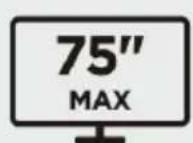
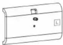
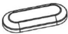
Line drawing of a mechanical cart with wheels and a horizontal panel (no text or symbols)EASEL STUDIO TV CART WITH CABINET
(SUITABLE FOR 49-75" TVS)
KATVCAR75LM
SAFETY & WARNINGS
Read the entire user guide before you start installation and assembly. If you have any questions regarding any of the instructions or warnings, contact your local distributor for assistance.
CAUTION: Use with products heavier than the rated weights indicated may result in instability causing possible injury.
- Please closely follow the assembly instructions. Improper installation may result in damage or serious personal injury.
- Safety gear and proper tools must be used. This product should only be installed by professionals.
- This product includes an anti-tip kit that must be used in conjunction with the product and will prevent the unit from falling or tipping over. Follow the enclosed information to properly install these safety accessories.
- This product is designed to be installed on solid concrete walls, masonry walls or wood stud walls.
- Make sure that the supporting surface will safely support the combined weight of the equipment and all attached hardware and components.
- Use the mounting screws provided and DO NOT OVER TIGHTEN mounting screws.
- This product contains small items that could be a choking hazard if swallowed. Keep these items away from children.
- This product is intended for indoor use only. Using this product outdoors could lead to product failure and personal injury.
- Never exceed the maximum load capacity of 50kg or it may result in product failure or personal injury.
IMPORTANT: Ensure that you have received all parts according to the component checklist prior to installation. If any parts are missing or faulty, contact your place of purchase for a replacement.
MAINTENANCE: Check that the product is secure and safe to use at regular intervals (at least every three months).
VESA Compatible
200x200 300x200 400x200
300x300 400x300
400x400 600x400

COMPONENTS

A (x1)

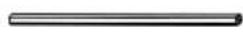
E (x1)
I (x1)
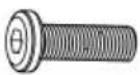
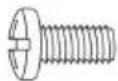
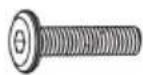
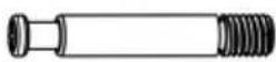
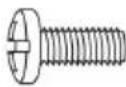
M M8x25
Screw (x4)
Q Screw
cover (x14)
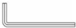
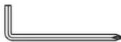
U 5mm Allen
Key (x1)
M-B M8x16
Screw (x4)

M-F Spacer (x4)

B (x1)
F (x1)
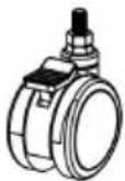
J Castors (x4)
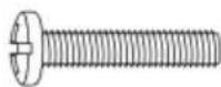
N M6x25
Screw (x4)
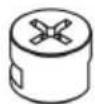
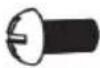
R Cam
Connector (x14)
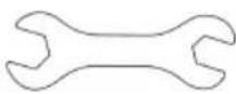
V 14-17mm
Spanner (x1)
M-C M6x30
Screw (x4)

M-G Spacer (x4)
C (x1)
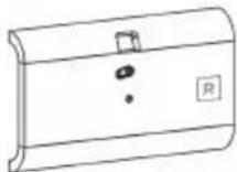
G (x1)

K (x2)
M4x8
Screw (x2)
S Cam Screw
(x14)
W Screw
cover (x2)

M-D M8x35
Screw (x4)
D (x2)
H (x2)
L M6x12 Screw (x2)
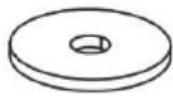
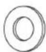
P Washer (x4)
T 4mm Allen Key
M-A M6x14 Screw (x4)
M-E D8 Washer (x4)
ASSEMBLY
Step 1:
Note: Lock the brakes on the casters (J) to avoid any sudden movements during installation.
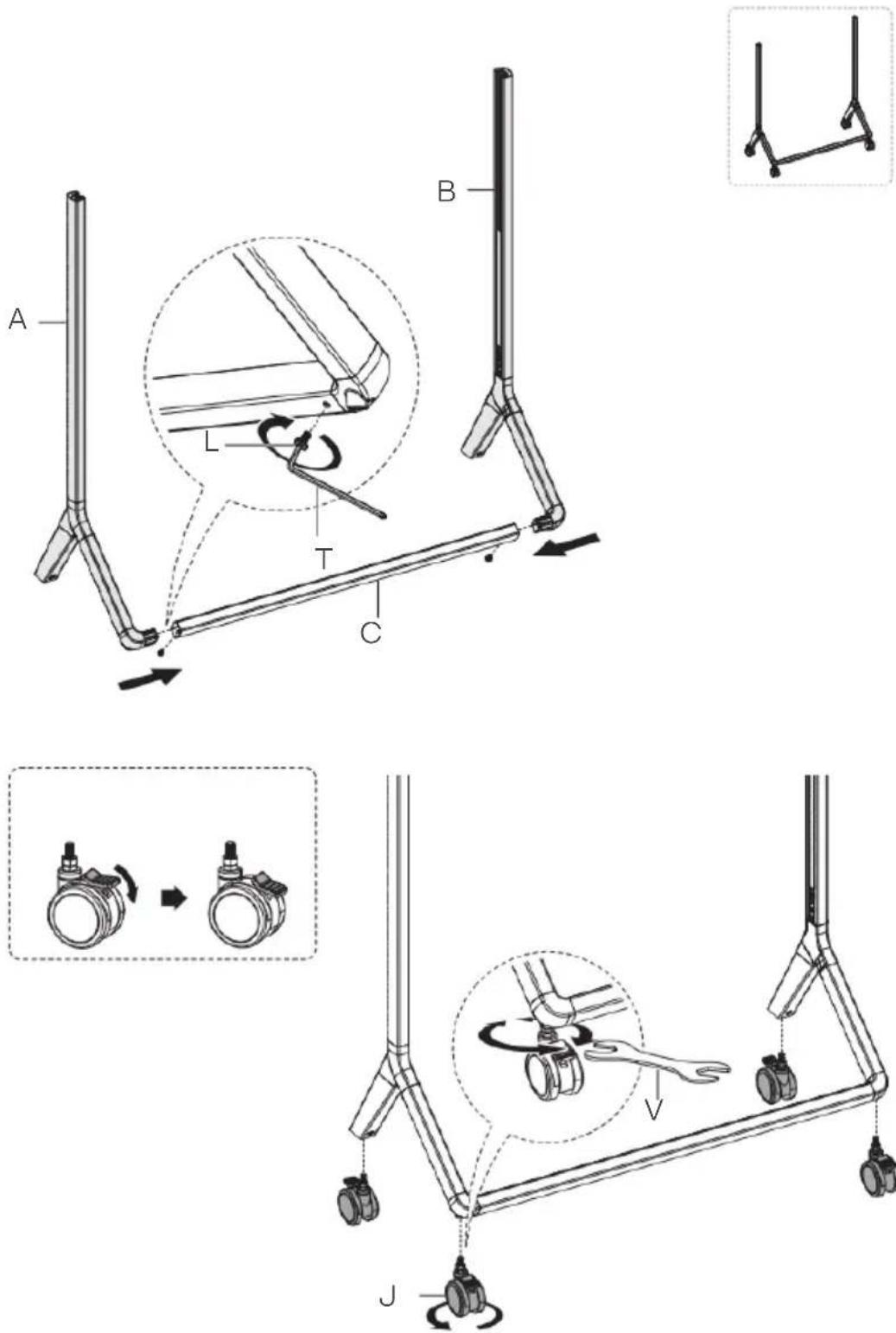
text_image
Technical diagram illustrating mechanical assembly steps with labeled components A, B, C, T, L, and J, including a zoomed-in view of the process.Step 2:
- Attach the parts (D) to part (E) using cam screws (S) and cam connectors (R).
• Cover the cam screws using the screw covers (Q).
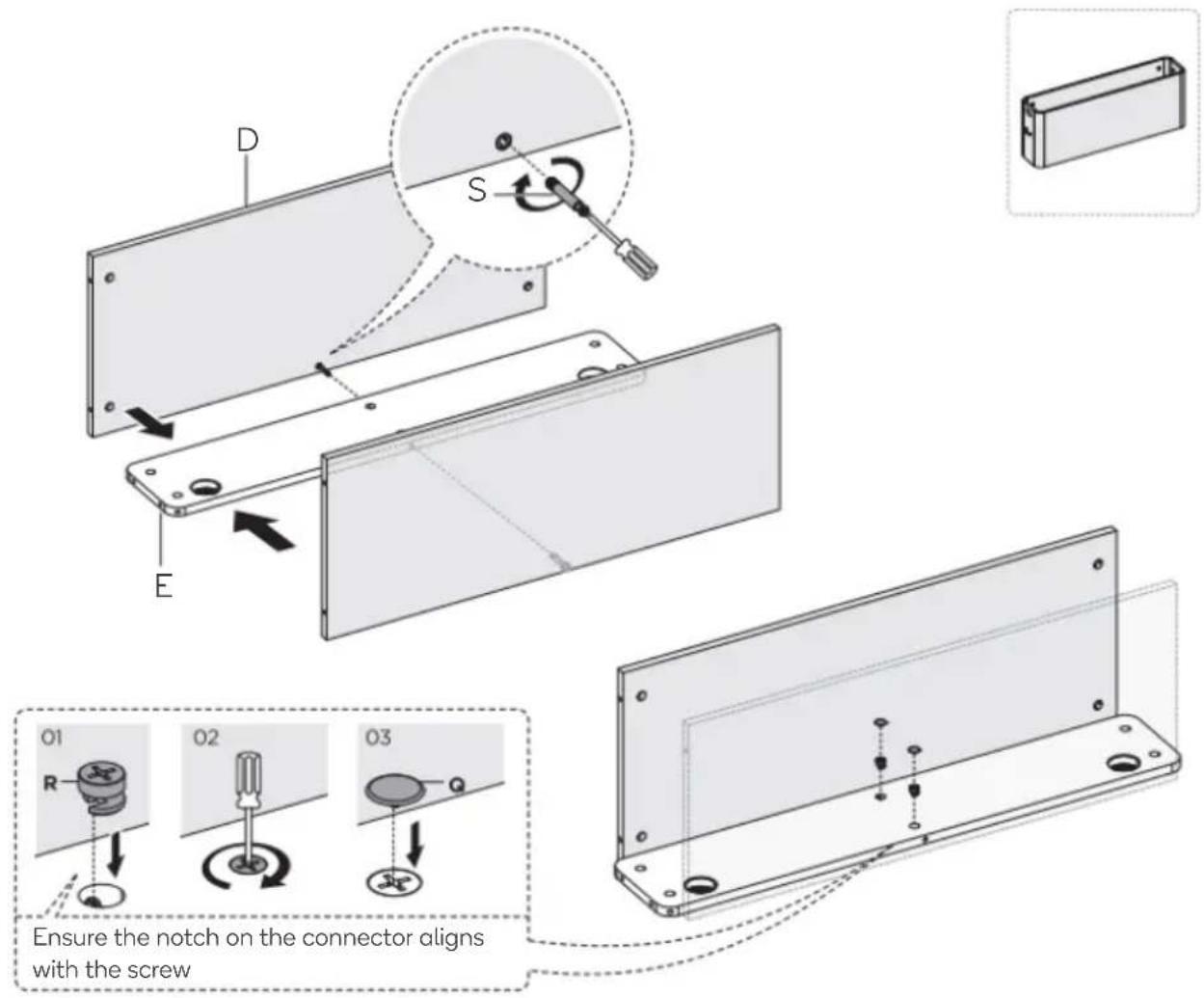
text_image
D S E O1 R O2 O3 Ensure the notch on the connector aligns with the screwStep 3:
- Assemble the side plates (F, G) using cam screws (S) and cam connectors (R). Ensure panel (F) is positioned on the left side and panel (G) on the right side.

text_image
Technical diagram of a mechanical assembly with labeled components F, G, and T/R, showing internal components and assembly steps.Step 4:
Attach the cabinet to the stand and secure it in place using M6x25 screws (N) and washers (P) into the two lower installation holes.

text_image
Note: Do not tighten the screws T N PStep 5:
- Tilt the cabinet up and using cable management strip, route the TV cables down the left side of the stand.
- Lower the front of the cabinet and install and tighten M6x25 screws (N) and washers (P) into the two upper installation holes.
- Tighten the screws on lower installation holes.
• Cover the screws using the screw covers (W).
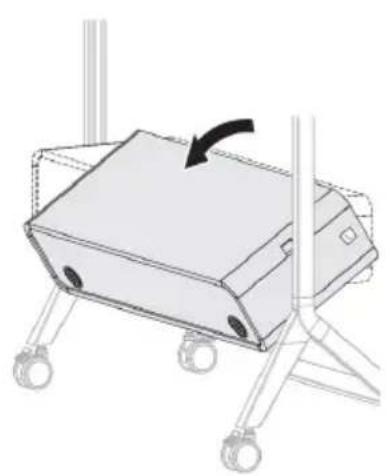
natural_image
Diagram of a mechanical device with wheels and a rotating arrow, no text or symbols present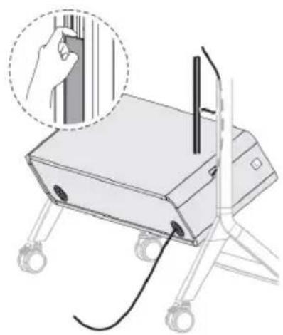
natural_image
Illustration of a portable electronic device with a hand inserting a cable, no text or symbols present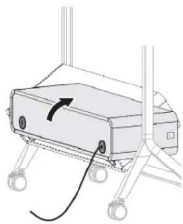
natural_image
Diagram of a robotic device with a curved arrow indicating motion or force, mounted on a wheeled base (no text or symbols present)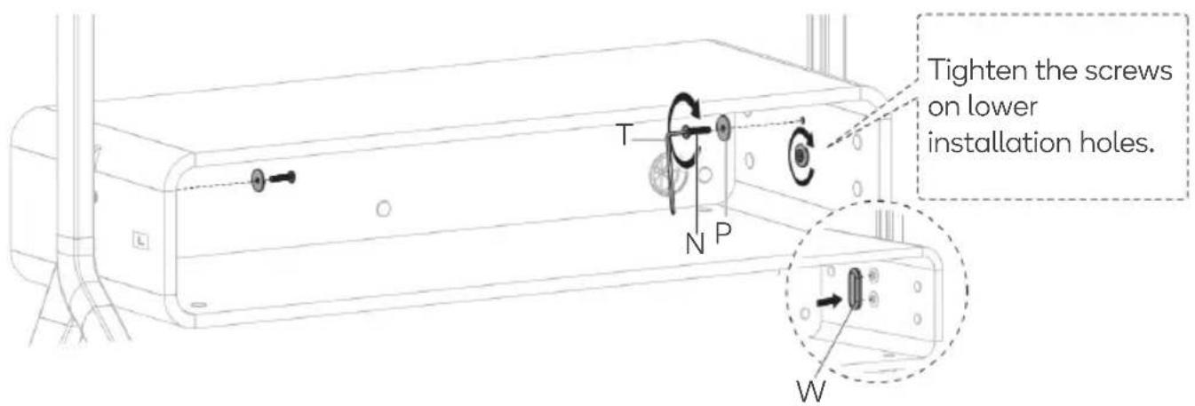
text_image
Tighten the screws on lower installation holes. T N P WTighten the screws on lower installation holes.
Step 6:
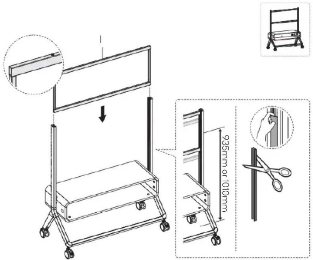
- Ensure the 2 limiting screws are facing upwards and insert part (I) into the stand.
- Secure part (I) in place using 4 M8x25 screws (M) and attach the 2 end caps (K).
Note: If the TV is in the lower position the cable management strips will need to be shortened.
text_image
935mm or 1010mm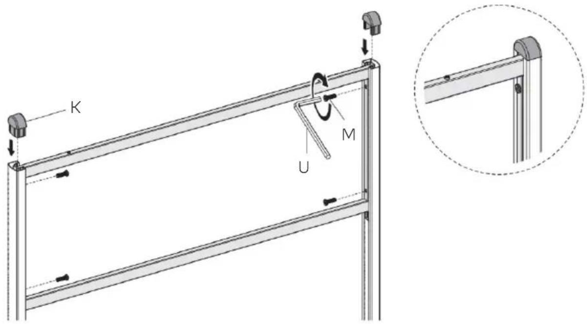
text_image
K M UStep 7:
Align the brackets (H) with your TV's VESA holes and secure using supplied screws ("M-" set), Washer (M-E) and spacers (M-F, M-G) depending on required length.
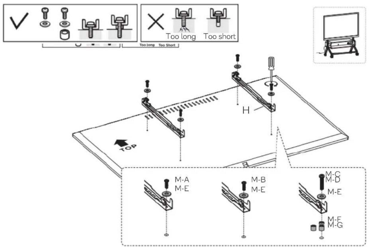
text_image
✓ Too long Too short Too long Too Short H TOP M-A M-E M-B M-E M-C M-D M-E M-F M-GStep 8:
Hook the TV with brackets installed onto the stand. Two people should carry the TV to prevent damage.
Note: Centre the TV bracket arms between the two limiting screws.
Once in place, use fasteners (O) to secure the brackets in place.
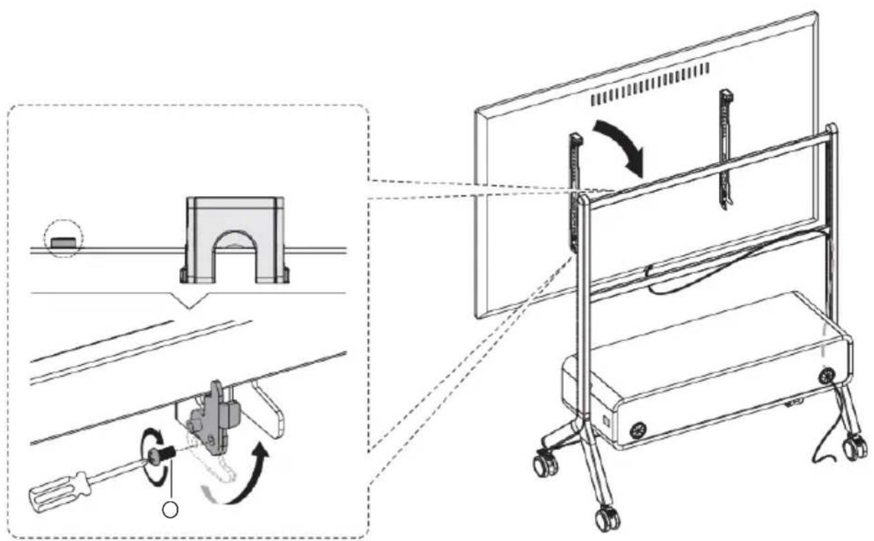
text_image
Technical diagram illustrating a mechanical assembly with labeled components and motion arrows, including a tool and a monitor setup.NOTES
Need more information?
We hope that this user guide has given you the assistance needed for a simple set-up.
For the most up-to-date guide for your product, as well as any additional assistance you may require, head online to help.kogan.com
kogan.com