DR203BGLP - Stove DANBY - Free user manual and instructions
Find the device manual for free DR203BGLP DANBY in PDF.

User questions about DR203BGLP DANBY
0 question about this device. Answer the ones you know or ask your own.
Ask a new question about this device
Download the instructions for your Stove in PDF format for free! Find your manual DR203BGLP - DANBY and take your electronic device back in hand. On this page are published all the documents necessary for the use of your device. DR203BGLP by DANBY.
USER MANUAL DR203BGLP DANBY
Owner's Manual....1 - 26
Danby Products Limited, Guelph, Ontario, Canada N1H 6Z9
Danby Products Inc. Findlay, Ohio, U.S.A. 45840
www.danby.com

Printed in China | Imprimé en Chine | Impreso en China
2024.04.29
Welcome
Welcome to the Danby family. We are proud of our quality products and we believe in dependable service. We suggest that you read this owner's manual before plugging in your new appliance as it contains important operation information, safety information, troubleshooting and maintenance tips to ensure the reliability and longevity of your appliance.
Visit www.Danby.com to access self service tools, FAQs and much more. For additional assistance call 1-800-263-2629.
Note the information below; you will need this information to obtain service under warranty.
You must provide the original purchase receipt to validate your warranty and receive service.
Model Number: ____
Serial Number: ____
Date of Purchase: ____
Need Help?
Before you call for service, here are a few things you can do to help us serve you better.
Read this owner's manual:
It contains instructions to help you use and maintain your appliance properly.
If you receive a damaged appliance:
Immediately contact the retailer or builder that sold you the appliance.
Save time and money:
Check the troubleshooting section at the end of this manual before calling. This section will help you solve common problems that may occur.

natural_image
Simple black-and-white icon of a telephone handset inside a circle (no text or symbols)1-800-26- Danby
(1-800-263-2629)

Important Safety Information READ AND FOLLOW ALL SAFETY INSTRUCTIONS
WARNING - If the information in this manual is not followed exactly, a fire or explosion may result, causing property damage, personal injury or death.
- Do not store or use gasoline or other flammable vapors and liquids in the vicinity of this or any other appliance.
• Installation and service must be performed by a qualified installer, service agency or the gas supplier.
WHAT TO DO IF YOU SMELL GAS
- Do not try to light any appliance.
- Do not touch any electrical switch.
- Do not use any phone in the building.
- Immediately call your gas supplier from a neighbor's phone. Follow the gas supplier's instructions.
- If you cannot reach your gas supplier, call the fire department.
WARNING - CARBON MONOXIDE
It is highly recommended to install a carbon monoxide detector in your home.
Check local and national regulations concerning installing and maintaining carbon monoxide detectors.
IN THE COMMONWEALTH OF MASSACHUSETTS
- This product must be installed by a licensed plumber or gas fitter.
- When using ball-type gas shut-off valves, they shall be the T-handle type.
- A flexible gas connector, when used, must not exceed 3 feet in length.
WARNING - TIP OVER HAZARD
- A child or adult can tip the appliance and be killed.
- Verify the anti-tip bracket has been properly installed and engaged to the floor or wall.
- Ensure the anti-tip bracket is re-engaged when the range is moved by sliding the anti-tip arm under the bracket.
- Do not operate the range without the anti-tip bracket in place and engaged.
- Failure to follow these instructions can result in death or serious burns to children or adults.
ANTI-TIP BRACKET
To reduce the risk of the appliance tipping over, an anti-tip bracket is provided that must be installed before operating the appliance. See installation instructions shipped with the bracket for complete details.
- Anti-tip bracket
- Right side panel
- Rear wall
- Anti-tip bracket
- Anti-tip arm

natural_image
Technical line drawing of a mechanical bracket or clamp assembly (no text or symbols)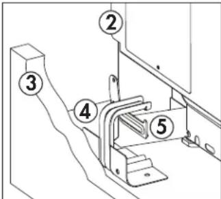
text_image
Technical diagram showing labeled mechanical components with numbered annotationsTo check if the bracket is installed and engaged properly, look underneath the range to see that the anti-tip arm attached to the right side panel is engaged on the bracket. On some models, the storage drawer or kick panel can be removed for easier inspection.
If visual inspection is not possible, slide the range forward, confirm the anti-tip bracket is securely attached to the floor or wall and slide the range back so the anti-tip arm slides under the anti-tip bracket. If the range is pulled from the wall for any reason, always repeat this procedure to verify that the range is properly secured by the anti-tip bracket.
SAVE THESE INSTRUCTIONS!

Important Safety Information READ AND FOLLOW ALL SAFETY INSTRUCTIONS
WARNING
NEVER use this appliance as a space heater to heat or warm the room. Doing so may result in carbon monoxide poisoning and overheating of the oven.
GENERAL SAFETY REQUIREMENTS
Use this appliance for its intended purpose as described in this Owner's Manual.
Have your range installed and properly grounded by a qualified installer in accordance with the provided installation instructions. Any adjustment and service should be performed only by a qualified gas range installer or service technicians. Do not attempt to repair or replace any part of your range unless it is specifically recommended in this guide.
Your range is shipped from the factory set for use with natural gas. It can be converted for use with LP gas. If required, these adjustments must be made by a qualified technician in accordance with the installation instructions and local codes. The agency performing this work assumes responsibility for the conversion.
Have the installer show you the location of the range gas shut-off valve and how to turn it off if necessary.
Plug your range into a 120-volt grounded outlet only. Do not remove the round grounding prong from the plug. If in doubt about the grounding of the home electrical system, it is your responsibility and obligation to have an ungrounded outlet replaced with a properly grounded, three prong outlet in accordance with the National Electrical Code. Do not use an extension cord with this appliance.
Before performing any service, unplug the range or disconnect the power supply at the household distribution panel by removing the fuse or switching off the circuit breaker.
Be sure all packing materials are removed from the range before operating to prevent ignition of these materials.
Avoid scratching or impacting glass doors, the cooktop or control panel. Doing so may lead to glass breakage. Do not cook on a product with broken glass. Shock, fire or cuts may occur.
Do not leave children alone or unattended in an area where an appliance is in use. They should never be allowed to climb, sit or stand on any part of the appliance.
Do not store items of interest to children above a range or on the backguard of a range - children climbing on the range to reach items could be seriously injured.
Do not allow anyone to climb, stand or hang on the oven door, drawer or cooktop. They could damage the range or tip it over causing severe injury or death.
Never block the vents (air openings) of the range. They provide the air inlets and outlets that are necessary for the range to operate properly with correct combustion. Air openings are located at the rear of the cooktop, at the top and bottom of the oven door, and at the bottom of the range under the warming drawer, lower oven drawer or kick panel.
Use only dry pot holders—moist or damp pot holders on hot surfaces may result in burns from steam. Do not let pot holders touch surface burners, burner grates, or oven heating elements. Do not use a towel or other bulky cloth in place of pot holders.
Be careful not to touch hot surfaces of the range. Potentially hot surfaces include burners, grates, cooktop, backguard, oven and door interior and crevices around the oven door.
Do not heat unopened food containers. Pressure could build up and the container could burst, causing an injury.
Cook meat and poultry thoroughly - meat to at least an internal temperature of 160°F and poultry to at least an internal temperature of 180°F. Cooking to these temperatures usually protects against foodborne illness.
SAVE THESE INSTRUCTIONS!

Important Safety Information READ AND FOLLOW ALL SAFETY INSTRUCTIONS
WARNING - FLAMMABLE MATERIALS
Do not store or use flammable materials in an oven or near the cooktop, including paper, plastic, pot holders, linens, wall coverings, curtains, drapes and gasoline or other flammable vapors and liquids.
Never wear loose-fitting or hanging garments while using the appliance. Avoid storing commonly used items in cabinets above the range and be careful when reaching over the range. Clothing in close proximity to burners or hot surfaces may ignite causing severe burns.
Do not let cooking grease or other flammable materials accumulate in or near the range. Grease in the oven or on the cooktop may ignite.
Clean ventilating hoods frequently. Grease should not be allowed to accumulate on the hood or filter.
WARNING - IN CASE OF FIRE
In the event of a fire, never pick up a flaming pot or pan. Turn the burner off if it is safe to do so. Extinguish the fire with a dry chemical or foam-type extinguisher.
Do not use water on grease fires. Water will spread the grease and will not extinguish the fire. Smother the fire with a tight fitting pot lid, cookie sheet or flat tray or use dry chemical or foam-type extinguisher.
If there is a fire in the oven during baking, smother the fire by closing the oven door and turning the oven off or use dry chemical or foam-type extinguisher.
COOKTOP SAFETY INSTRUCTIONS
Never leave the range unattended while a surface burner is ON. Foods, especially oily foods, may ignite resulting in fire that could spread to surrounding cabinets.
Never leave oil unattended while frying. If allowed to heat beyond its smoking point, oil may ignite resulting in fire that may spread to surrounding cabinets. Use a deep fat thermometer whenever possible to monitor oil temperature.
To avoid oil spillover and fire, use a minimum amount of oil when shallow pan-frying and avoid cooking frozen foods with excessive amounts of ice.
Use proper pan size and avoid pans that are unstable or easily tipped. Select cookware that is matched to the size of the burner. Burner flames should be adjusted so that they do not extend beyond the bottom of the pan. Excessive flames may be hazardous.
Always use the LITE position when igniting the top burners and make sure the burners have ignited.
When using glass or ceramic cookware, make sure it is suitable for cooktop service; others may break because of sudden changes in temperature.
To minimize the possibility of burns, ignition of flammable materials and spillage, the handle of a container should be turned toward the center of the range without extending over nearby burners.
When preparing flaming foods under a hood, turn the fan on.
Do not use a wok with a round metal support ring. The ring may trap heat and block air to the burner resulting in a carbon monoxide hazard.
Do not attempt to lift the cooktop if your range has sealed surface burners. Doing so may damage the gas tubing to the surface burners resulting in a gas leak and risk of fire.
Do not use aluminum foil to cover the grates or line any part of the cooktop. Doing so may result in carbon monoxide poisoning, overheating of the cooktop surfaces, or a potential fire hazard.
SAVE THESE INSTRUCTIONS!

Important Safety Information READ AND FOLLOW ALL SAFETY INSTRUCTIONS
WARNING
NEVER cover any slots, holes or passages in the oven bottom or cover and entire rack with materials such as aluminum foil. Doing so blocks air flow through the oven and may cause carbon monoxide poisoning. Aluminum foil linings may also trap heat, causing a fire hazard.
OVEN SAFETY INSTRUCTIONS
Stand away from the range when opening the oven door. Hot air or steam which escapes can cause burns to hands, face and/or eyes.
Keep the oven free from grease build-up. Grease in the oven may ignite.
Place oven racks in desired location while oven is cool. If rack must be moved while oven is hot, do not let potholder contact the hot heating element in the oven.
Place oven racks in desired location while oven is cool. If rack must be moved while oven is hot, be careful to avoid touching hot surfaces.
Pull the oven rack to the stop-lock position when loading and unloading food from the oven. This helps prevent burns from touching hot surfaces of the door and oven walls.
Do not leave items such as paper, cooking utensils or food in the oven when not in use. Items stored in an oven can ignite.
Do not leave items on the cooktop near the oven vent which is in the center of the backguard. Items may overheat resulting in a risk of fire or burns.
When using cooking or roasting bags in the oven, follow the manufacturer's directions.
Never broil with door open. Open-door broiling is not permitted due to overheating of control knobs.
LOWER OVEN DRAWER SAFETY INSTRUCTIONS
The purpose of the warming drawer is to hold hot cooked foods at serving temperature. Bacteria will grow very rapidly in food that is between 40 and 140°F. Do not put cold food in the warming drawer. Do not keep food in the warming drawer for more than 2 hours. Failure to follow these instructions may result in foodborne illness.
Do not leave paper products, plastics, canned food or combustible materials in the drawer. They may ignite.
Do not touch the heating element or the interior surface of the drawer. These surfaces may be hot enough to cause burns.
Use care when opening the drawer. Open the drawer a crack and let hot air or steam escape before removing or replacing food. Hot air or steam that escapes can cause burns to hands, face and/or eyes.
Do not use aluminum foil to line the warming drawer. Foil is an excellent heat insulator and will trap heat beneath it. This will upset the performance of the drawer and potentially cause a fire hazard.
WARNING
Read all safety instructions before using the product. Failure to follow these instructions may result in fire, electric shock, serious injury or death.
INSTALLATION INSTRUCTIONS
FOR YOU SAFETY
Do not store or use combustible materials, gasoline or other flammable vapors and liquids in the vicinity of this or any other appliance.
If you smell gas:
- Open windows.
- Do not touch electrical switches.
- Extinguish any open flame.
- Immediately call your gas supplier.
REQUIRED TOOLS
- Phillips screwdriver
- Flat blade screwdriver
- Pencil and ruler
- Pipe wrench
- Open end or adjustable wrench
- Level
- Drill, awl or nail
MATERIALS YOU WILL NEED
- Gas-line shut-off valve.
- Pipe joint sealant or UL-approved pipe thread tape with Teflon* that resists action of natural and LP gases.
- Flexible metal appliance connector (1/2" I.D.) A 5 foot length is recommended for ease of installation but other lengths are acceptable. Never use an old connector when installing a new range.
- Flare union adapter for connection to gas supply line (3/4" or 1/2" NPT x 1/2" I.D.)
- Liquid leak detector or soapy water.
- Lag bolt or 1/2" O.D. sleeve anchor (for concrete floors only).
*Teflon is a registered trademark of DuPont.

text_image
① ② ③ ④ ⑤ ⑥ ⑦INSTALLATION INSTRUCTIONS
INSTALLATION SAFETY INSTRUCTIONS
Read these instructions completely and carefully. Failure to follow these instructions can result in electrical shock, fire, serious injury, or death.
Improper installation, adjustment, alteration, service or maintenance can cause injury or property damage. Refer to this manual. For assistance or additional information, consult a qualified installer, service agency, manufacturer (dealer) or the gas supplier.
Never reuse old flexible connectors. The use of old flexible connectors can cause gas leaks and personal injury. Always use new flexible connectors when installing a gas appliance.
Leak testing of the appliance shall be conducted according to the manufacturer instructions.
Remove all packing material and literature from oven before connecting gas and electrical supply to range.
Do not attempt to operate the oven of this range during a power failure.
Have your range installed by a qualified installer.
Your range must be electrically grounded in accordance with local codes or, in the absence of local codes, in accordance with the National Electrical Code, ANSI/NFPA 70, latest edition.
Your range must conform with local gas codes or, in the absence of local codes, in accordance with the National Fuel Gas Code, ANSI Z223.1/NFPA 54.
Appliances designed for manufactured mobile home installation must conform with the Manufactured Home Construction and Safety Standard, Title 24 CFR, Part 3280, [formerly the Federal Standard for Mobile Home Construction and Safety, Title 24, HUD (part 280)] or with local codes where applicable.
Appliances designed for Recreational Park Trailers must conform with the state or other codes or, in the absence of such codes, with the Standard for Recreational Park Trailers, ANSI A1 19.5.
Before installing your range on linoleum or any other synthetic floor covering, make sure the floor covering can withstand 180°F without shrinking, warping or discoloring. Do not install the range over carpeting unless a sheet of 1/4" thick plywood or similar insulator is placed between the range and carpeting.
Make sure the cabinets, floor, and wall coverings around the range can withstand heat generated by the range up to 200^ F.
Avoid placing cabinets above the range. To reduce the hazard caused by reaching over the open flames of operating burners, install a ventilation hood over the range that projects forward at least 5" beyond the front of the cabinets.
The ventilating hood must be constructed of sheet metal not less than 0.0122" thick. Install above the cooktop with a clearance of not less than 1/4" between the hood and the underside of the combustible material or metal cabinet. The hood must be at least as wide as the appliance and centered over the appliance. Clearance between the cooking surface and the ventilation hood surface must never be less than 24". Exception: Installation of a listed microwave oven or cooking appliance over the cooktop shall conform to the installation instructions packed with that appliance.
If cabinets are placed above the range, allow a minimum clearance of 30 " between the cooking surface and the bottom of unprotected cabinets.
If a 30" clearance between cooking surface and overhead combustible material or metal cabinets cannot be maintained, protect the underside of the cabinets above the cooktop with not less than 1/4" insulating miliboard covered with sheet metal not less than 0.0122" thick. Clearance between the cooking surface and protected cabinets MUST NEVER BE LESS THAN 24".
The vertical distance from the plane of the cooking surface to the bottom of adjacent overhead cabinets extending closer than 1" to the plane of the range sides must not be less than 18". (See the Dimensions and Clearances Illustration in this section).
INSTALLATION INSTRUCTIONS
DIMENSIONS AND CLEARANCES
Provide adequate clearances between the range and adjacent combustible surfaces. These dimensions must be met for safe use of the range. The placement of the power outlet and the opening of the piping can be adjusted to comply with the specific requirements.
The range may be placed with 0" clearance below the cooktop and at the back wall.

text_image
B 30" Minimum C 18" 36"
text_image
A E 36" ¾ ± ¼" DA: 19 3/4"
B: 19 3/4"
C: 2"
D: 44 3/8"
E: 41 3/4"
LOCATION
Do not locate the range where it may be subject to strong drafts. Any openings in the floor or wall behind the range should be sealed. Make sure the openings around the base of the range that supply fresh air for combustion and ventilation are not obstructed by carpeting or woodwork.
Your range, like many other household items, is heavy and can settle into soft floor coverings such as cushioned vinyl or carpeting. Use care when moving the range on this type of flooring. It is recommended that the following simple and inexpensive instructions be followed to protect your floor.
The range should be installed on a sheet of plywood or similar material. When the floor covering ends at the front of the range, the area that the range will rest on should be built up with plywood to the same level or higher than the floor covering.
This will allow the range to be moved for cleaning or servicing. Also, make sure your floor covering will withstand 180^ F.
Make sure the cabinets and wall coverings around your range can withstand the heat generated (up to 200^ F) by the range.
IMPORTANT
Remove all tape and packaging.
Make sure the burners are properly seated and level.
Take the accessory pack out of the oven or drawer.
Check to be sure that no range parts have come loose during shipping.
INSTALLATION INSTRUCTIONS
POWER CORD AND STRAIN RELIEF INSTALLATION
Remove the wire cover on the lower back of the range by removing its top center screw. Do not discard this screw.
Remove the knockout ring located on the bracket directly below the terminal block. To remove the knockout, use a pair of pliers to bend the knockout ring away from the bracket and twist until the ring is removed.
-
Terminal block
-
Knockout ring in bracket
-
Knockout ring removed

text_image
Technical diagram showing three labeled components of an electrical contactor or connector assembly, including housing, mounting holes, and a ring.For power cord installations
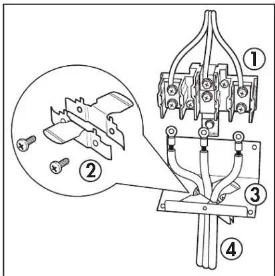
Assemble the strain relief in the hole of the bracket. If tabs are present at the end of the winged strain relief they can be removed for a better fit.
Insert the power cord through the strain relief and tighten. Allow enough slack to easily attach the cord terminals to the terminal block.
Do not install the power cord without a strain relief. The strain relief bracket should be installed before reinstalling the rear range wiring cover.
- Terminal block
- Strain relief
- Bracket
- Power cord
Purchase a squeeze connector matching the diameter of your conduit and assemble it in the hole of the bracket. Insert the conduit through the squeeze connector and tighten. Allow enough slack to easily attach the wires to the terminal block.
Do not install the conduit without a squeeze connector. The squeeze connector should be installed before reinstalling the rear range wiring cover.
- Terminal block
- Squeeze connector
- Bracket
- Conduit
text_image
Technical diagram of a mechanical clamp or clamp assembly with numbered parts and an inset showing disassembled parts.
text_image
Technical diagram of a mechanical device with numbered components and a magnified inset showing internal components.INSTALLATION INSTRUCTIONS
3 WIRE POWER CORD INSTALLATION
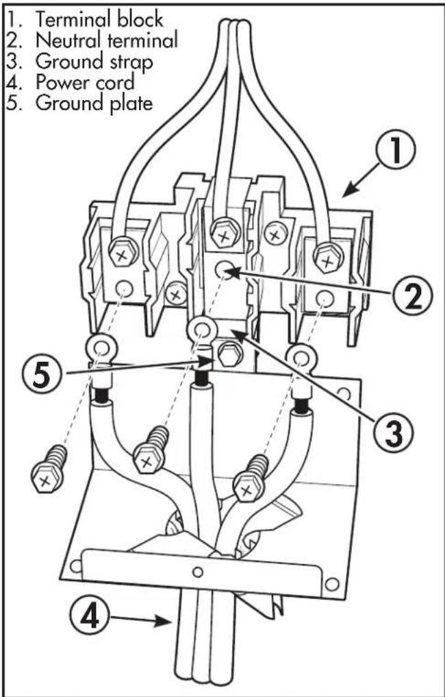
The neutral or ground wire of the power cord must be connected to the neutral terminal located in the center of the terminal block. The power leads must be connected to the lower left and the lower right terminals of the terminal block.
- Remove the three lower terminal screws from the terminal block.
- Insert the three terminal screws through each power cord terminal ring and into the lower terminals of the terminal block.
- Be certain that the center wire is connected to the center lower position of the terminal block.
- Tighten screws securely into the terminal block.
- Do not remove the ground strap connection.
text_image
1. Terminal block 2. Neutral terminal 3. Ground strap 4. Power cord 5. Ground plateINSTALLATION INSTRUCTIONS
4 WIRE POWER CORD INSTALLATION
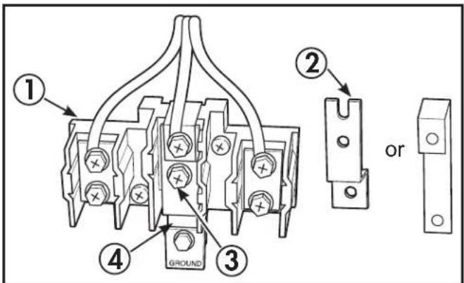
The neutral wire of the supply circuit must be connected to the neutral terminal located in the lower center of the terminal block. The power leads must be connected to the lower left and the lower right terminals of the terminal block. The 4th grounding lead must be connected to the frame of the range with the ground plate and the ground screw.
- Remove the three lower terminal screws from the terminal block.
- Remove the ground screw and ground plate and retain them.
-
Cut and discard the ground strap. Do not discard any screws.
-
Insert the one ground screw into the power cord ground wire terminal ring, through the ground plate and into the frame of the range.
-
Insert the three terminal screws that were removed earlier through each power cord terminal right and into the lower terminals of the terminal block.
-
Be certain that the center wire is connected to the center lower position of the terminal block.
-
Tighten the screws securely into the terminal block.
Before
- Terminal block
- Ground strap
- Neutral terminal
- Cut and discard the ground strap
text_image
① ② GROUND ③ ④ orAfter
- Terminal block
- Neutral terminal
- Ground plate (grounding to range)
- Ground screw

text_image
Technical diagram of a mechanical contactor or electrical component with numbered parts and labeled connection points.INSTALLATION INSTRUCTIONS
ELECTRICAL CONNECTIONS
Electrical requirements:
120 volt, 60 hertz, properly grounded dedicated circuit protected by a 15 amp or 20 amp circuit breaker or time delay fuse.
NOTE: Use of automatic, wireless, or wired external switches that shut off power to the appliance are not recommended for this product.
WARNING SHOCK HAZARD: This appliance must be properly grounded. Failure to do so can result in electric shock.
The power cord of this appliance is equipped with a three-prong (grounding) plug which mates with a standard three-prong grounding wall receptacle to minimize the possibility of electric shock hazard from this appliance.
The customer should have the wall receptacle and circuit checked by a qualified electrician to make sure the receptacle is properly grounded.
Where a standard two-prong wall receptacle is encountered, it is the personal responsibility and obligation of the customer to have it replaced with a properly grounded three-prong wall receptacle.
DO NOT, UNDER ANY CIRCUMSTANCES, CUT OR REMOVE THE THIRD (GROUND) PRONG FROM THE POWER CORD.
DO NOT USE AN ADAPTER.
DO NOT USE AN EXTENSION CORD.
A word about GFCIs - GFCIs are not required or recommended for gas range receptacles. Ground Fault Circuit Interrupters (GFCIs) are devices that sense leakage of current in a circuit and automatically switch off power when a threshold leakage level is detected. These devices must be manually reset by the consumer. The National Electrical Code requires the use of GFCIs in kitchen receptacles installed to serve countertop surfaces. Performance of the range will not be affected if operated on a GFCI-protected circuit but occasional nuisance tripping of the GFCI breaker is possible.
ANTI-TIP BRACKET INSTALLATION
- Anti-tip arm on the back of the appliance
- Anti-tip bracket
- Screw must enter wood or concrete
- Wall sill plate
- Screw must enter wood
text_image
Technical diagram showing labeled components of a piping or duct system with numbered parts 1 to 5.To reduce the risk of the appliance tipping, the anti-tip bracket must be installed before operation.
Note: The installation of the anti-tip bracket must meet all local codes for securing the appliance.
The anti-tip bracket must be secured to either the rear wall or the floor and must be positioned in such a way that it will overhang the anti-tip arm on the rear of the appliance.
Rear wall installation
Use the two screws provided to secure the bracket to the rear wall. The screws must enter a wood sill plate. If the wall contains any metal studs or similar materials, or if the back of the appliance cannot reach the rear wall, the floor installation should be used.
Floor installation
Wood floor: Use the two screws provided to secure the bracket to the floor.
Concrete floor:
- Mark the location where the screws need to be installed.
- Use a power drill and a concrete bit to drill a 5/32" pilot hole 2" deep into the concrete at the center of each of the marked locations.
- Use the two screws provided to secure the bracket to the floor.
Double check the installation
After installing the bracket, slide the appliance into its final location. Look underneath the appliance and ensure that the anti-tip arm attached to the side panel of the appliance is engaging the bracket.
INSTALLATION INSTRUCTIONS
INSTALL THE RANGE
1. Provide adequate gas supply
Your range is designed to operate at a pressure of 5" of water column on natural gas or, if desired for LP gas (propane or butane), 10" of water column.
Make sure you are supplying your range with the type of gas for which it is designed.
This range is convertible for use on natural or propane gas. If you decide to use this range on LP gas, conversion must be made by a qualified LP installer before attempting to operate the range on that gas.
For proper operation, the pressure of natural gas supplied to the regulator must be between 6" and 13" of water column.
For LP gas, the pressure supplied must be between 11" and 13" of water column.
When checking for proper operation of the regulator, the inlet pressure must be at least 1" greater than the operating (manifold) pressure as given above.
The pressure regulator located at the inlet of the range must remain in the supply line regardless of whether natural or LP gas is being used.
A flexible metal appliance connector used to connect the range to the gas supply line should have an I.D. of 1/2" and be 5 feet in length for ease of installation. In Canada, flexible connectors must be single wall metal connectors no longer than 6 feet in length.
INSTALL THE RANGE
2. Connect the range to gas
Shut off the main gas supply valve before disconnecting the old range and leave it off until the new hook-up has been completed. Don't forget to relight the pilot on other gas appliances when you turn the gas back on.
Because hard piping restricts movement of the range, the use of a CSA International-certified flexible metal appliance connector is recommended unless local codes require a hard-piped connection.
Never use an old connector when installing a new range. If the hard piping method is used, you must carefully align the pipe, the range cannot be moved after the connection is made.
To prevent gas leaks, put pipe joint compound on, or wrap pipe thread tape with Teflon around all male (external) pipe threads.
Installation steps:
- Install a manual gas line shut-off valve in the gas line in an easily accessed location outside of the range. Make sure everyone operating the range knows where and how to shut off the gas supply to the range.
- Install male 1/2" flare union adapter to the 1/2" NPT internal thread at inlet of regulator. Use a backup wrench on the regulator fitting to avoid damage. When installing the range from the front, remove the 90° elbow for easier installation.
- Install male 1/2" or 3/4" fl are union adapter to the NPT internal thread of the manual shut-off valve to keep it from turning.
- Connect flexible metal appliance connector to the adapter on the range. Position range to permit connection at the shut-off valve.
- When all connections have been made, make sure all range controls are in the off position and turn on the main gas supply valve. Use a liquid leak detector at all joints and connections to check for leaks in the system.
INSTALLATION INSTRUCTIONS
WARNING
Fire hazard: Do not use a flame to check for gas leaks.
Recommended gas and electric supply location
When using test pressures greater than 1/2 psig to pressure test the gas supply system of the residence, disconnect the range and individual shut-off valve from the gas supply piping. When using test pressures of 1/2 psig or less to test the gas supply system, simply isolate the range from the gas supply system by closing the individual shut-off valve.
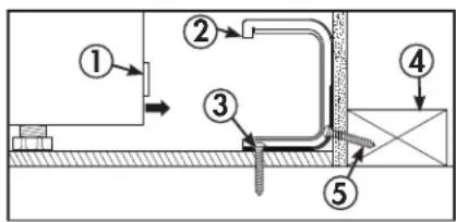
Note: Recommended gas hook-up locations behind the range. Gas and shut-off valve should not protrude more than 2" from the wall to allow the range to rest against the wall.
Check local codes before making connections.

text_image
A 30" Min. 13" Max 1/4" 18" Min. C D 12" 36" 1. Electrical connection area 2. Gas hook-up area A. 20 3/8" B. (minimum distance to walls above the cooktop on each side): 2" C. 2" D. 2 1/2" 14" 8" 3" 8" 8" 5" 2" 2" 2" ① ②INSTALLATION INSTRUCTIONS
FLEXIBLE CONNECTOR HOOKUP EXAMPLE
To the installer: Inform the consumer of the location of the gas shut-off valve and leave these instructions with the consumer for future use.
Note: The arrow indicates the direction of gas flow into the range.
- Pressure regulator
- Adapter
- Flex connector (4 1/2 feet maximum)
- Adapter
- Gas 'shut off valve
- 1/2" or 3/4" gas pipe
text_image
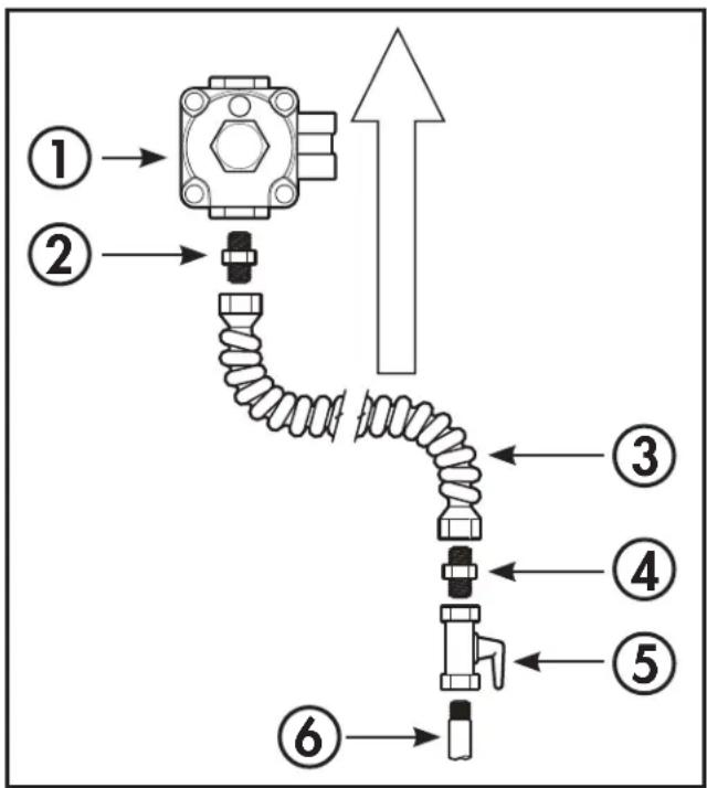
Diagram of a mechanical assembly with numbered components and directional arrows indicating flow or movement.RIGID CONNECTOR HOOKUP EXAMPLE
To the installer: Inform the consumer of the location of the gas shut-off valve and leave these instructions with the consumer for future use.
Note: The arrow indicates the direction of gas flow into the range.
- Pressure regulator
- Black iron pipe 4 1/2"
- 90° elbow
- Nipple (may not be required)
- 90° elbow
- Black iron pipe
- Union
- Nipple
- Gas shut off valve
- 1/2" or 3/4" gas pipe

flowchart
graph TD
    A["①"] --> B["Valve"]
    C["②"] --> B
    D["③"] --> B
    B --> E["Valve"]
    E --> F["④"]
    F --> G["Pipe"]
    G --> H["⑤"]
    G --> I["⑥"]
    G --> J["⑦"]
    G --> K["⑧"]
    G --> L["⑨"]
    G --> M["⑩"]
INSTALL THE RANGE
3. Seal the openings
Seal any openings in the wall behind the range and in the floor under the range when hookups are completed.
INSTALLATION INSTRUCTIONS
INSTALL THE RANGE
4. Electric ignition
There are separate ignition devices for the left and right hand surface burners. Both of these ignition devices are ON when any knob is turned to the LITE setting. The ignition devices will spark as long as any of the top burner knobs are at the LITE setting.
In the event of an electrical power failure, the top knobs can still be used. To light a burner, hold a lit kitchen match adjacent to the top burner to be used and turn the valve knob to LITE.
USE EXTREME CAUTION WHEN LIGHTING A BURNER THIS WAY.
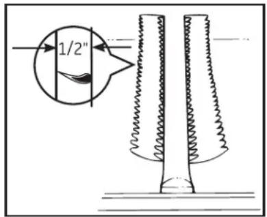
5. Adjust the oven burner air shutter
For Natural Gas: The oven burner flame should be a clean, blue flame with distinct inner cones approximately 1/2" long. A soft, lazy flame with indistinct cones means too much gas or not enough air. A noisy lifting flame means too much air.
text_image
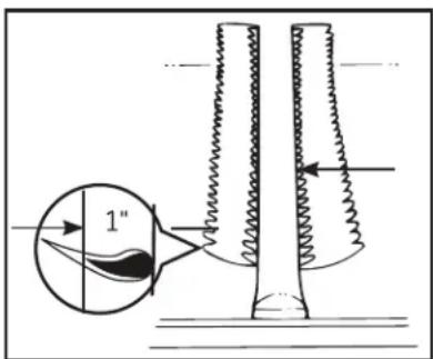
1/2"For LP gas: The flame should have approximately 1-inch blue cones. After 30 seconds of burner operation, check for flames lifting off the burner ports. If lifting is observed, gradually reduce the air shutter opening until flames are stabilized. Some yellow tipping may be normal for LP gas.
text_image
1"INSTALL THE RANGE
If burner adjustment is necessary:
Loosen the lock screw located at the top of the air shutter, then rotate the air shutter to the correct position and retighten the screw.
- Air shutter
- Lock screw

text_image
Technical diagram showing a device with labeled parts, including numbered annotations ① and ②.The oven burner flame can be checked as follows (without burner baffle in place):
- To correct a yellow flame, increase size of air shutter opening.
- To correct a lifting, but distinct, blue flame, decrease size of air shutter opening.
The air shutter should be set approximately 2/3 open for natural gas, and approximately full open for LP gas.
INSTALLATION INSTRUCTIONS
INSTALL THE RANGE
6. Quality of flames
The combustion quality of burner flames needs to be determined visually.
A: Yellow flames; call for service
B: Yellow tips on outer cones; normal for LP gas
C: Soft blue flames; normal for natural gas
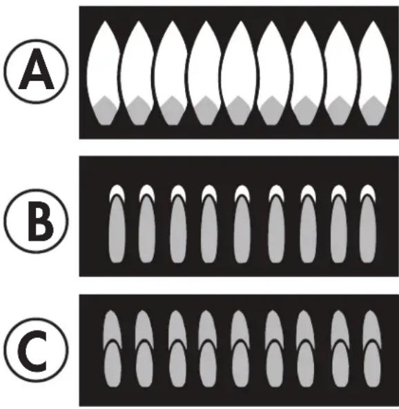
text_image
A B C7. Replace the oven parts
Once all adjustments are completed, ensure all oven parts are installed correctly such as the bottom drawer, the oven shelves and the oven door.
INSTALL THE RANGE
8. Level the range
Check that the appliance is level using a spirit level or a clear measuring cup partially filled with water. Ensuring that the oven is level will ensure even cooking.
Use an open end or adjustable wrench to adjust the leveling legs. Turn the leg clockwise to raise the range. Turn the leveling leg counterclockwise to lower the range.
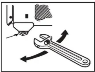
text_image
Diagram illustrating the use of a wrench to adjust tool position, with directional arrows indicating movement.INSTALLATION CHECK LIST
- Make sure all controls are in the OFF position.
- Make sure the flow of combustion and ventilation air to the range is unobstructed.
- Make sure all oven parts are installed correctly.
- Double check that the anti-tip bracket is installed and working correctly.
CONVERT TO LP GAS
This range leaves the factory set for use with natural gas. The conversion to LP gas must be performed by a qualified LP gas installer.
The conversion instructions and LP orifices can be found attached to the back of the range.
OPERATING INSTRUCTIONS
USING GAS SURFACE BURNERS
Before lighting a gas burner:
• Make sure all burners are in place.
- Make sure all grates on the range are properly places before using any burner.
After lighting a gas burner:
- Do not operate the burner for an extended period of time without cookware on the grate. The finish on the grate may discolor or chip without cookware to absorb the heat.
- Be sure the burners and grates are cool before you place your hand, a pot holder, cleaning cloths or other materials on them.
How to light a gas surface burner:
- Make sure all the surface burners are placed in their respective positions.
- Push the control knob in and turn it to the LITE position.
- You will hear a clicking noise, this is the sound of the electric spark igniting the burner.
- Turn the knob to adjust the flame size. If the knob stays at LITE, it will continue to click.
- When one burner is turned to LITE, all the burners spark. Do not attempt to disassemble or clean around any burner while another burner is on. An electric shock may result, which could cause you to knock over hot cookware.
- Watch the flame, not the knob, as you adjust heat. When fast heating is desired, the flame size on a gas burner should match the cookware you are using.
- Flames larger than the bottom of the cookware will not result in faster heating and may be hazardous.

natural_image
Hand holding a small electronic component with an arrow indicating left motion (no text or symbols)WARNING
Flames that are not covered by cookware may present a risk of burns or clothing ignition. Never let flames extend beyond the sides of the cookware.
ACCEPTABLE COOKWARE
Aluminum: Medium-weight cookware is recommended because it heats quickly and evenly. Most foods brown evenly in an aluminum skillet. Use saucepans with tight-fitting lids when cooking with minimum amounts of water.
Cast-Iron: If heated slowly, most skillets will give satisfactory results.
Enamelware: Under some conditions, the enamel of some cookware may melt. Follow cookware manufacturer's recommendations for cooking methods.
Glass: There are two types of glass cookware—those for oven use only and those for top-of-range cooking (saucepans, coffee and teapots). Glass conducts heat very slowly.
Heatproof Glass Ceramic: Can be used for either surface or oven cooking. It conducts heat very slowly and cools very slowly. Check cookware manufacturer's directions to be sure it can be used on gas ranges.
Stainless Steel: This metal alone has poor heating properties and is usually combined with copper, aluminum or other metals for improved heat distribution. Combination metal skillets usually work satisfactorily if they are used with medium heat as the manufacturer recommends.
IN CASE OF POWER FAILURE
In case of a power failure, you can light the surface burners on your range with a match. Hold a lit match to the burner ports, then slowly turn the control knob to the LTE position. Use extreme caution when lighting burners this way.
Surface burners in use when an electrical power failure occurs will continue to operate normally.
OPERATING INSTRUCTIONS
USING THE OVEN
Oven controls
The oven is controlled by the oven temp knob. It can take up to 90 seconds before the flame comes on.
After the oven reaches the selected temperature, the oven burner maintains the selected temperature.
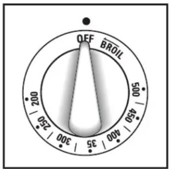
text_image
OFF BRDIL 500 / 450 400 / 35 300 / 250 200 / 150IN CASE OF POWER FAILURE
The oven or broiler cannot be lit during a power failure.
If the oven is in use when a power failure occurs, the oven burner shuts off. This is because the flow of gas is automatically stopped and will not resume until power is restored.
UPPER OVEN VENT
Your oven is vented through ducts at the rear of the range. Do not block these ducts when cooking in the oven - it is important that the flow of hot air from the oven and fresh air to the oven burner be uninterrupted. Avoid touching the vent openings or nearby surfaces during oven or broiler operations - they may become hot.
Handles of pots and pans on the cooktop may become hot if left too close to the vent.
Do not leave plastic or flammable items on the cooktop - they may melt or ignite if left too close to the vent.
Do not leave closed containers of the cooktop. The pressure in closed containers may increase, which may cause them to burst.
Metal items will become very hot if they are left on the cooktop, and could cause burns.
OVEN SHELVES
The oven shelves are designed with stop-locks so that when they are placed correctly on the shelf supports, they will stop before coming completely out of the oven and will not tilt when food is being removed or added.
To remove the shelves from the oven, pull the shelf outward, tilt the front end upward and pull it out.
To replace the shelves, place the shelf on the support with the stop locks facing up and toward the back of the oven. Tilt up the front and push the shelf toward the back of the oven until it goes past the bump on the shelf support, then lower the front of the shelf and push it all the way into the oven.
The oven has four different shelf support positions to accommodate different cooking requirements.

natural_image
Diagram of a kitchen appliance with a tray and ventilation system, showing airflow direction (no text or symbols)SHELF POSITIONS
- Most baking is done on the second or third shelf position from the bottom of the oven.
- When baking multiple items, use two shelves positioned on the second and fourth shelf supports from the bottom of the oven.
- Roasting is usually done on the bottom shelf position.
- As a general rule, place most foods in the middle of the oven on the second or third shelf.
- Pans should not touch each other or the walls of the oven. Allow 1 to 1 1/2 inches of space between pans as well as from the back of the oven, the door and the sides. If you need to use two shelves stagger the pans so one is not directly above the other.
OPERATING INSTRUCTIONS
OVEN BAKING AND ROASTING
- Position the shelves in the oven. If cooking on two shelves at the same time, stagger the pans for the best heat circulation.
- Place the food on the center of the oven shelf. Allow at least 2 inches between the end of the pan and the oven wall or any adjacent pans.
- Turn oven temperature knob to the desired temperature.
- Check the food regularly. Remove once done and ensure the oven is turned off.
BAKING AND ROASTING TIPS
- Follow a tested recipe and measure the ingredients carefully. If you are using a package mix, follow label directions.
- Do not open the oven door while baking or roasting. Heat will be lost and the cook time might need to be extended. If you must open the door, open it partially and close it as quickly as possible.
- Roasting is cooking by dry heat. Tender meat or poultry can be roasted uncovered. Roasting temperatures, which should be low and steady, keep spattering to a minimum. When roasting, it is not necessary to sear, baste, cover, or add water to the meat.
- Frozen roasts of meat can be cooked without thawing, but allow 10 to 25 minutes of additional time per pound of meat (10 minutes per pound for roasts under 5 pounds, more time for larger roasts).
- Thaw frozen poultry before roasting to ensure even cooking. Some commercial frozen poultry can be cooked successfully without thawing. Follow directions given on package label.
SAFE COOKING
The USDA recommends the following minimum safe internal temperatures:
- Raw beef, pork, lamb and veal steaks or chops: 145°F as measured with a food thermometer before removing meat from the heat source. For safety and quality, allow meat to rest for at least three minutes before carving or consuming.
- Raw ground beef, pork, lamb or veal: 160°F as measured with a food thermometer.
- Poultry: 165°F as measured with a food thermometer.
- For more information, visit: www.isitdoneyet.gov or call toll free to the USDA meat and poultry hotline at 1-888-674-6854.
OVEN BROILING
Broiling is cooking food by direct heat from above the food. Most fish and tender cuts of meat can be broiled. The range has a compartment below the oven for broiling. A specially designed broiler pan allows dripping fat to drain away from the food. Both the oven door and broiler compartment drawer should be closed during broiling.
- Preheating the boiler drawer is not necessary and can produce poor results.
- If the meat has fat or gristle around the edge, cut vertical slashes through both about 2" apart. If desired, fat may be trimmed, leaving a layer about 1/8" thick.
- Place the meat on a broiler grid in a broiler pan designed for broiling. Always use the grid so the fat drips into the broiler pan; otherwise the juices may become hot enough to catch fire.
- Place the food in the broiler and close the door.
- Turn the oven temperature knob to BROIL.
- Food can be turned during broiling if necessary. Be cautious of hot air or steam when opening the oven door.
- Make sure to turn the oven temperature knob to OFF once broiling is complete.
BROILING TIPS
- Always use the broiler pan and grid that comes with your range. It is designed to minimize smoking and spattering by trapping juices in the shielded lower part of the pan.
- For steaks and chops, slash fat evenly around the outside edges of the meat. Use tongs to turn the meat over to prevent piercing the meat and losing juices.
- If desired, marinate meats before broiling, or brush with barbecue sauce in the last 5-10 minutes only.
- When arranging the food on the pan, do not let fatty edges hang over the sides because dripping fat could soil the oven.
- Frozen steaks can be broiled by positioning the rack at the next lowest rack position and increasing the cooking time 1 1/2 times per side.
- Aluminum foil can be used to line the broiler pan and grid, however, it must be molded tightly to the grid and slits must be cut in the foil so that fat and juices can leak through into the lower part of the pan.
OPERATING INSTRUCTIONS
ADJUST THE OVEN THERMOSTAT
You may find that the new oven cooks differently than the one it replaced. Use the new oven for a few weeks to become familiar with it. If you still find the oven is too hot or too cold, you can adjust the thermostat.
Do not use thermometers, such as those found in grocery stores to check the temperature of the oven. They are not calibrated for high temperatures and can vary from 20 - 40 degrees.
This adjustment will not affect the broiling temperatures. The adjustment will be retained after a power failure.
- Pull the oven temperature knob off the range and look at the back of it. To make an adjustment, loosen by one turn the two screws on the back of the knob. Do not completely remove the screws.
- With the back of the knob facing you, hold the outer edge of the knob with one hand and turn the front of the knob with the other hand.
- To increase the oven temperature, move the top screw toward the right.
- To decrease the oven temperature, move the top screw toward the left.
- You will hear a click for each notch you move the knob. Each click will change the oven temperature approximately 10^ F. The range is plus or minus 60^ F from the arrow. We suggest that you adjust the temperature by one click and then test the oven performance before adjusting further.
- After the adjustment is made, retighten the screws so they are snug. Be careful not to over-tighten.
- Replace the knob, matching the flat area of the knob to the shaft.

text_image
LOOSEN SCRENS TOROATE MAX COOLER HOTTERALUMINUM FOIL
Do not use aluminum foil to line the bottom of the oven. The foil will trap heat below and upset the performance of the oven. Foil can melt and permanently damage the bottom of the oven. Damage from improper use of aluminum foil is not covered by the product warranty.
Foil may be used to catch spills by placing a sheet on a lower rack, several inches below the food. Do not use more foil than necessary and never entirely cover an oven rack with aluminum foil. Keep foil at least 1 to 1 1/2 inches from oven walls to prevent poor heat circulation.
OVEN MOISTURE
As the oven heats up, the temperature change of the air in the oven may cause water droplets to form on the door glass. These droplets are harmless and will evaporate as the oven continues to heat up.
OVEN AIR VENTS
Never block the air vents. They provide the air inlet and outlet that are necessary for the range to operate properly with correct combustion.
Air openings are located at the rear of the cooktop, at the top and bottom of the oven door, and at the bottom of the range.
Vent appearance and location may vary.
CARE & MAINTENANCE
BURNER GRATES
The range has two or three professional-style double grates. These grates are position specific. For maximum stability, these grates should only be used in their proper position; they cannot be interchanged left to right or front to back.
For convenience, the undersides of the left and right grates are marked "LEFT FRONT" and "RIGHT FRONT". Make sure the front portion of both grates is in front. The middle grate has a bow in front. Make sure the bowed portion is toward the front of the range. In addition, the middle grate is supported by the left and right grates and must be installed last for stability.
Cleaning burner grates
Lift out when cool. Grates should be washed regularly and, of course, after spillovers. Wash them in hot, soapy water and rinse with clean water. When replacing the grates, be sure they are positioned securely over the burners.
Replace the grates so that continuous arcs are formed with the center ribs of all three grates.
Do not operate a burner for an extended period of time without cookware on the grate. The finish on the grate may chip without cookware to absorb the heat.
To get rid of burned-on food, place the grates in a covered container. Add 1/4 cup ammonia and let soak several hours or overnight. Wash, rinse well and dry.
Although they are durable, the grates will gradually lose their shine, regardless of the best care you can give them. This is due to their continual exposure to high temperatures. You will notice this sooner with lighter color grates.
CLEANING
Cooktop surface
To avoid damaging the porcelain-enamel surface of the cooktop and to prevent it from becoming dull, clean up spills right away. Foods with a lot of acid or foods with high sugar content could cause a dull spot if allowed to set.
When the surface has cooled, wash and rinse. For other spills such as fat spattering, wash with soap and water once the surface has cooled. Then rinse and polish with a dry cloth.
Control panel and knobs
It is a good idea to wipe the control panel after each use of the oven. Use a damp cloth to clean or rinse. For cleaning, use mild soap and water or a 50/50 solution of vinegar and water. For rinsing, use clean water. Polish dry with a soft cloth.
Do not use abrasive cleansers, strong liquid cleaners, plastic scouring pads or oven cleaners on the control panel as they will damage the finish.
Do not try to bend knobs by pulling them up or down or by hanging a towel or other such loads. This can damage the gas valve shaft.
The control knobs may be removed for easier cleaning. Make sure the knobs are in the OFF positions and pull them straight off the stems for cleaning. The knobs can be cleaned in a dishwasher or they may also be washed with soap and water. Make sure the insides of the knobs are dry before replacing.
Replace the knobs in the OFF position to ensure proper placement. Note that knobs are not interchangeable. Be sure to reinstall the knobs to the original location.
Metal parts can be cleaned with soap and water. Do not use steel wool, abrasives, ammonia, acids or commercial oven cleaners. Dry with a soft cloth.
CARE & MAINTENANCE
Oven shelves and broiler rack
The shelves and broiler rack can be cleaned by hand using soap and water or with an abrasive cleaner or steel wool. After cleaning, rinse the shelves and broiler rack with clean water and dry with a clean cloth.
After cleaning, grease all oven rack edges with a light coating of vegetable oil. This will help maintain the ease of sliding the racks in and out of the oven.
Porcelain oven interior
With proper care, the porcelain enamel interior will retain its finish for many years.
Soap and water can be used to clean the interior. Heavy splattering or spills may require cleaning with a mild abrasive cleaner.
Do not allow spills with high acid content such as milk, tomatoes, fruit juices or pie filling, to remain on the surface. They may cause dull spots even after cleaning.
Household ammonia may make cleaning easier. Place 1/2 cup of ammonia in a shallow glass pan and leave in a cold oven over night. The ammonia fumes will help loosen burned on grease and food.
Cautions about using spray-on oven cleaners
Do not spray oven cleaner on the electrical controls and switches as it could cause a short circuit and result in sparking or fire.
Do not allow a film from the oven cleaner to remain on the temperature sensor as it could cause the oven to heat improperly. The sensor is located on the top of the oven. Carefully wipe the bulb clean after each oven cleaning, being careful not to move the sensor since a change in its position could affect how the oven bakes.
Do not spray oven cleaner on the outside of the oven door, handles or any exterior surface of the oven, cabinet or painted surfaces. The cleaner can damage these surfaces.
Removable oven bottom
On some models the bottom panel of the oven is removable and can be washed separately.
To remove the oven bottom:
- Remove the knurled screw in the front of the oven bottom.
- Grasp each side of the oven bottom and push back.
- Lift the front up and pull it out of the oven.
To replace the oven bottom:
- Grasp each side of the oven bottom and guide its rear tabs into the slots in the back of the oven.
- Lower the oven bottom and pull it forward until it is secure under the front oven floor edge.
- On models so equipped, replace the knurled screw in the front of the oven bottom.
NOTE: If the oven bottom is replaced incorrectly, it may warp and cause undesirable baking results.
Broiler compartment
The broiler pan is held in place in the broiler rack.
To remove the broiler pan:
- Gently pull forward on the drop down broiler door.
- Pull the broiler rack with pan forward until the rack stops.
- Grasp the broiler pan and remove it from the broiler rack.
To replace the broiler pan:
- Slide the broiler pan onto the rack and push both the broiler pan and the rack all the way into the broiler compartment.
- Close the broiler door.
If a spillover occurs in the broiler compartment, allow the compartment to cool first. You can clean the compartment with soap and water, a mild abrasive cleanser, soap-filled scouring pads or an oven cleaner following package directions.
CARE & MAINTENANCE
Broiler pan and guard
After broiling, remove the broiler pan from the oven. Remove the grid from the pan. Carefully pour out grease from the pan into a proper container. Wash and rinse the broiler pan and grid in hot water with a soap-filled or plastic scouring pad.
If food has burned on, sprinkle the grid with detergent while hot and cover with wet paper towels or a dishcloth. Soaking the pan will remove burned on foods.
Do not store a soiled broiler pan and grid anywhere in the range.
Removable oven door
The oven door is removable but it is heavy. It is recommended that at least two people work together to remove it.
To remove the door:
- Open the door to the full open position.
- Pull the hinge locks up over the hinge hooks on both sides.
- Grasp the door firmly on both sides, lift slightly and pull it straight out and away from the oven.
To replace the door:
- Firmly grasp both sides of the door at the top.
- Insert and seat the upper and lower hinge arms into the oven slots.
- Push the hinge locks down from the hinge hooks.
- Close the oven door and make sure it is working properly. If it seems uneven or does not close completely, remove it again and repeat the steps to replace it.
Note: Do not attempt to close the door until it is properly installed. The hinges could be damaged.
Glass door window
To clean the outside of the glass door window, use a glass cleaner. Rinse and polish with a dry cloth.
Avoid scratching or impacting the glass window. Doing so may cause the glass to break.
OVEN LIGHT REPLACEMENT
Important: Before replacing the oven light bulb, make sure the electrical power is disconnected from the appliance. Failure to do so may result in electric shock or burn.
Be sure to let the light cover and bulb cool completely before replacing.
Removing the oven door can make this process easier.
To remove the light cover:
- Twist the lens counterclockwise roughly 1/4 turn to remove. Do not remove any screws to remove the light cover.
- Do not touch the light bulb with a wet cloth. Replace the light bulb with a 40 watt appliance light bulb.
To replace the light cover:
- Line up the tabs of the lens with the tabs on the light housing and rotate clockwise by roughly 1/4 turn to install.
TROUBLESHOOTING
Danby Consumer Care: 1-800-263-2629
Hours of operation:
Monday to Thursday 8:30 am - 6:00 pm Eastern Standard Time
Friday 8:30 am - 4:00 pm Eastern Standard Time
Information in this manual is subject to change without notice.
| PROBLEM POSSIBLE CAUSE | |
| No power • A fuse may be blown or the circuit breaker tripped• Plug not fully inserted into the wall outlet | |
| Surface elements not working properly | • Burner holes on the side or around the top of the burner may be clogged.• Burners may not be fitted correctly onto the mounting brackets. |
| Burners have yellow or yellow-tipped flames | • The combustion quality of burner flames needs to be determined visually. See the “Quality of flames” section of the installation instructions for more information. |
| Burner flames very large or yellow • LP gas is improperly connected.• The thermostat capillary bulb must be clean and unobstructed.• The oven vent is blocked.• Oven control improperly set.• Improper size of cookware is being used. | |
| Strong odor • Improper air to gas ratio in the oven.• An odor from the insulation around the oven liner is normal the first few times the oven is used. | |
| Surface burners light but oven does not | • The oven gas shut off valve may have been accidentally moved during cleaning or moving. Raise the cook top and look for the gas shut off lever in the left rear corner. Ensure the lever is in the open position. |
| Oven light does not work • Light bulb is loose• Light switch is not operating correctly | |
LIMITED "IN HOME" WARRANTY
This quality product is warranted to be free from manufacturer's defects in material and workmanship, provided that the unit is used under the normal operating conditions intended by the manufacturer.
This warranty is available only to the person to whom the unit was originally sold by Danby Products Limited (Canada) or Danby Products Inc. (U.S.A.) (hereafter "Danby") or by an authorized distributor of Danby, and is non-transferable.
TERMS OF WARRANTY
Plastic parts are warranted for thirty (30) days from the date of purchase, with no extensions provided.
First 12 months During the first twelve (12) months, any functional parts of this product found to be defective, will be repaired or replaced, at warrantor's option, at no charge to the original purchaser.
To obtain service Contact the dealer where the unit was purchased, or contact the nearest authorized Danby service depot, where service must be performed by a qualified service technician. If service is performed on the unit by anyone other than an authorized service depot, all obligations of Danby under this warranty shall be void.
Boundaries of in-home service Danby reserves the right to limit the boundaries of "In Home Service" to the proximity of an authorized service depot. Any appliance requiring service outside the limited boundaries of "In Home Service", will be the consumer's responsibility to transport at their own expense to the original point of purchase or a service depot for repair. If the appliance is installed in a location that is 100 kilometers (62 miles) or more from the nearest service center, it must be delivered to the nearest authorized Danby Service Depot by the purchaser.
Transportation charges to and from the service location are not protected by this warranty and are the responsibility of the purchaser.
Nothing within this warranty shall imply that Danby will be responsible or liable for any spoilage or damage to food or other contents of this appliance, whether due to any defect of the appliance, or its use, whether proper or improper.
EXCLUSIONS
Save as herein provided, by Danby, there are no other warranties, conditions, representations or guarantees, express or implied, made or intended by Danby or its authorized distributors and all other warranties, conditions, representations or guarantees, including any warranties, conditions, representations or guarantees under any Sale of Goods Act or like legislation or statute is hereby expressly excluded. Save as herein provided, Danby shall not be responsible for any damages to persons or property, including the unit itself, howsoever caused or any consequential damages arising from the malfunction of the unit and by the purchase of the unit, the purchaser does hereby agree to indemnify and hold harmless Danby from any claim for damages to persons or property caused by the unit.
GENERAL PROVISIONS
No warranty or insurance herein contained or set out shall apply when damage or repair is caused by any of the following:
1) Power failure.
2) Damage in transit or when moving the appliance.
3) Improper power supply such as low voltage, defective house wiring or inadequate fuses.
4) Accident, alteration, abuse or misuse of the appliance such as inadequate air circulation in the room or abnormal operating conditions (i.e. extremely high or low room temperature).
5) Use for commercial or industrial purposes (i.e. If the appliance is not installed in a domestic residence).
6) Fire, water damage, theft, war, riot, hostility, acts of God such as hurricanes, floods etc.
7) Service calls resulting in customer education.
8) Improper Installation (i.e. Building-in of a free standing appliance or using an appliance outdoors that is not approved for outdoor application, including but not limited to: garages, patios, porches or anywhere that is not properly insulated or climate controlled).
Proof of purchase date will be required for warranty claims; retain bills of sale. In the event that warranty service is required, present the proof of purchase to our authorized service depot.
Warranty Service
In Home
Danby Products Limited
PO Box 1778, Guelph, Ontario, Canada NIH 629
Telephone: (519) 837-0920 FAX: (519) 837-0449
1-800-263-2629
04/17
Danby Products Inc
PO Box 669, Findlay, Ohio, U.S.A. 45840
Telephone: (419) 425-8627 FAX: (419) 425-8629
Bienvenido
natural_image
Simple black-and-white icon of a telephone handset inside a circle (no text or symbols)1-800-26-Danby (1-800-263-2629)

natural_image
Technical line drawing of a mechanical bracket or clamp assembly (no text or symbols)
text_image
Technical diagram showing labeled components of a mechanical or electrical assembly with numbered parts 2, 3, 4, and 5.text_image
A E 36° ¾ ± ½" DA: 19 3/4"
B: 19 3/4"
C: 2"
D: 44 3/8"
E: 41 3/4"
UBICACIÓN
text_image
Technical diagram showing three labeled components of an electrical contactor or connector assembly: housing, mounting bracket, and washer.text_image
Technical diagram of a mechanical device with numbered components and an inset showing a disassembled part.text_image
Technical diagram of a mechanical device with numbered components and a magnified inset showing internal components.text_image
Technical diagram of a mechanical contactor or relay with numbered components and labeled partstext_image
Technical diagram of a mechanical contactor with numbered parts and labeled connection pointstext_image
Technical diagram showing labeled components of a mechanical or electrical assembly with numbered parts 1 to 5.text_image
Diagram of a mechanical assembly with numbered components and directional arrows indicating flow or movement.text_image
Technical diagram of a device with numbered components and labeled parts, likely illustrating a mechanical or electrical assembly.natural_image
Diagram showing a wrench tool interacting with a mechanical component, with directional arrows indicating movement (no text or symbols present)natural_image
Hand inserting a coin into a slot with an arrow indicating left motion (no text or symbols)ADVERTENCIA
natural_image
Diagram of a kitchen appliance with heat exchanger and directional arrows indicating airflow or movement (no text or symbols)POSICIONES DE ESTANTE
PROBLEMA CAUSA POSIBLE
Danby Products Limited
PO Box 1778, Guelph, Ontario, Canada N1H 6Z9
Telephone: (519) 837-0920 FAX: (519) 837-0449
1-800-263-2629
04/17
Danby Products Inc.
PO Box 669, Findlay, Ohio, U.S.A. 45840
Telephone: (419) 425-8627 FAX: (419) 425-8629
Danby Products Limited, Guelph, Ontario, Canada N1H 6Z9
Danby Products Inc. Findlay, Ohio, U.S.A. 45840
www.danby.com