BXT1 - TV wall mount SANUS - Free user manual and instructions
Find the device manual for free BXT1 SANUS in PDF.

User questions about BXT1 SANUS
0 question about this device. Answer the ones you know or ask your own.
Ask a new question about this device
Download the instructions for your TV wall mount in PDF format for free! Find your manual BXT1 - SANUS and take your electronic device back in hand. On this page are published all the documents necessary for the use of your device. BXT1 by SANUS.
USER MANUAL BXT1 SANUS
THE #1 TV MOUNT BRAND IN THE US.
BXT1 Instruction Manual

natural_image
Landscape painting of a vibrant sunset over rolling hills with colorful clouds and no visible text or symbols
natural_image
Technical line drawing of a metal frame with two vertical supports and mounting holes (no text or symbols)We'll Make It Stress-Free
If you have any questions along the way, just give us a call. 1-800-359-5520 (UK: 0800-056-2853) We're ready to help!
Milestone AV Technologies and its affiliated corporations and subsidiaries (collectively, "Milestone"), intend to make this manual accurate and complete. However, Milestone makes no claim that the information contained herein covers all details, conditions, or variations. Nor does it provide for every possible contingency in connection with the installation or use of this product. The information contained in this document is subject to change without notice or obligation of any kind. Milestone makes no representation of warranty, expressed or implied, regarding the information contained herein. Milestone assumes no responsibility for accuracy, completeness or sufficiency of the information contained in this document.
IMPORTANT SAFETY INSTRUCTIONS – SAVE THESE INSTRUCTIONS – PLEASE READ ENTIRE MANUAL PRIOR TO USE
Before getting started, let's make sure this mount is perfect for you!
| 1 Does your TV weigh (including accessories) more than ... |  For walls with wood studs, solid concrete or concrete block. For walls with wood studs, solid concrete or concrete block. |  For walls with steel studs. For walls with steel studs. | No — Perfect!Yes — This mount is NOT compatible. Visit MountFinder.Sanus.com or call 1-800-359-5520 (UK: 0800-056-2853) to find a compatible mount. | ||
| 2 What is your wall made of?CAUTION:DO NOT install into drywall alone | Drywall with wood studs?Perfect! Perfect! | Solid concrete or concrete block?[IMAGE] | 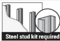 Drywall with steel studs?(not included) Drywall with steel studs?(not included) |  Unsure? Unsure? | |
| Call Customer Service: 1-800-359-5520 (UK: 0800-056-2853) | |||||
| 3 Do you have all the tools needed? | 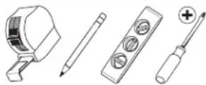 Tape Measure Pencil Level Screwdriver Tape Measure Pencil Level Screwdriver |  n)Electric Drill Socket Wrench n)Electric Drill Socket Wrench |  |  |  |
| 4 Ready to begin? | Please read through these instructions completely to be sure you're comfortable with this easy install process. Also check your TV owner's manual to see if there are any special requirements for mounting your TV.If you do not understand these instructions or have doubts about the safety of the installation, assembly or use of this product, contact Customer Service at 1-800-359-5520 (UK: 0800-056-2853).CAUTION: Avoid potential personal injuries and property damage!This product includes directions and hardware for use with wood stud, solid concrete and concrete block walls—DO NOT install into drywall alone.The wall must be capable of supporting five times the weight of the TV and mount combined.Do not use this product for any purpose not explicitly specified by manufacturer.Manufacturer is not responsible for damage or injury caused by incorrect assembly or use. | ||||
Parts and Hardware
WARNING: This product contains small items that could be a choking hazard if swallowed.
Before starting assembly, verify all parts are included and undamaged. If any parts are missing or damaged, do not return the damaged item to your dealer; contact Customer Service. Never use damaged parts!
NOTE: Not all hardware included will be used.
Parts and Hardware for STEP 1

text_image
TV Brackets 01 x1 02 x1 03 x4 M6 x 12mm 04 x4 M6 x 20mm 05 x4 M6 x 35mm TV Washers TV Washers 13 x4 M8/M8 TV Screws M8TV Screws M6 09 x4 M8x30 mm 06 x4 M8 x 16mm 10 x4 M8 x 35mm 07 x4 M8 x 20mm 11 x4 M8 x 40mm 08 x4 M8 x 25mm 12 x4 M8 x 45mm 14 x4 2.5mm22mm 15 x4Parts and Hardware for STEP 2

text_image
Wall Plate 16 x1
text_image
Lag Bolt 5/16 in. x 2 3/4 in. ⑰ x4For concrete installations ONLY
CAUTION: Do not use in drywall or wood Concrete Anchor

text_image
18 x4 UX10 x 60RHardware for STEP 2C Steel Stud Option [Steel Stud Anchor Kit is NOT INCLUDED]
Contact Customer Service at 1-800-359-5520 to have the additional hardware shipped directly to you.

text_image
Anchor S1 x4 x4 1/4-20 Snap Toggle BB
text_image
Screw 1/4-20 x 1.75S2 S3

Adjustments

text_image
Hex Key 3/16 in. 19 x1STEP 1
Attach Brackets to TV
1.1 Screw Diameter 1.2 Determine Spacers and Screw Length
Hand thread screws into the threaded inserts on the back of your TV to determine which screw diameter (M6, or M8) to use.

natural_image
Line drawing of a hand holding a device with a control panel (no text or symbols)M6

O
M8

○
a: Use no spacers for: Flat back TVs (AND TV closer to the wall).

b: Spacers supplied for:
• Round (irregular) back TVs
- Extra space needed (for cables or inset mounting holes)

text_image
b 14text_image
Diagram showing cable installation steps with labeled arrows and component details
natural_image
Diagram of a device with a magnified circular component, no text or symbols presentIf your TV included inset spacers or wall mount adapters, see Troubleshooting on PAGE 18.
CAUTION: Verify adequate thread engagement with your screw/washer/spacer combination AND TV bracket.(STEP 1.3)
- Too short will not hold the TV. - Too long will damage the TV.

▲ Too Short Too Long


1.3 Attach TV Brackets
Center the TV brackets 01 and 02 over your TV hole pattern as shown - making sure the brackets are level.

NOTE: The tilt tension knob Ⓣ on TV brackets 01 and 02 should be oriented to the outside edges.
Install using the spacer, TV screw and washer combination you selected for your TV.

text_image
Install using the spacer, TV screw and washer combination you selected for your TV. a | SCREW AND WASHER b | SPACER, SCREW AND WASHER 15 14 Adjust the straps to the bottom of the TV.STEP 2A
Attach Wall Plate to Wall

Wood Stud Installation

text_image
Min. 3 1/2 in. (89 mm) Min. 1 1/2 in. (38 mm) Min. 16 in. (406 mm) Max. 5/8 in. (16 mm)CAUTION: Avoid potential personal injuries and property damage!
- Drywall covering the wall must not exceed 5/8 in. (16 mm)
-
Minimum wood stud size: common 2 x 4 in. (51 x 102 mm) nominal 1½ x 3½ in. (38 x 89 mm)
• Minimum horizontal space between fasteners: 16 in. (406 mm)
• Stud centers must be verified -
Locate the stud. Verify the center of the stud using an awl, a thin nail, or an edge to edge stud finder. Mark the center of the stud with a pencil.
- Place the wall plate 16 at your desired height, over your stud center lines. Level the wall plate 16 and mark the four hole locations.

NOTE: For assistance in determining wall plate location, see Height Finder at sanus.com.

text_image
1
text_image
2 16- Drill the four pilot holes using a 7/32 in. (5.5 mm) diameter drill bit.
IMPORTANT: Pilot holes must be drilled to a depth of 2 3/4 in. (70 mm). Be sure you drill into the center of the stud.
- Install the wall plate 16 using four lag bolts 17. Firmly tighten all four lag bolts 17 until they are pulled flush against the wall plate 16.
CAUTION: Avoid potential personal injury or property damage! All four lag bolts 17 MUST BE firmly tightened to prevent unwanted movement of the wall plate 16. Ensure the wall plate is securely fastened to the wall before continuing on to the next step.
Go to STEP 3 on PAGE 15.

text_image
3 2 3/4 in. (70 mm) 7/32 in. (5.5 mm)
text_image
4 17 16STEP 2B
Attach Wall Plate to Wall

Solid Concrete or Concrete Block Installation
CAUTION: Avoid potential personal injuries and property damage!
-
Mount the wall plat 16 directly onto the concrete surface
• Minimum solid concrete thickness: 8 in. (203 mm)
● Minimum concrete block size: 8 x 8 x 16 in. (203 x 203 x 406 mm)
• Minimum horizontal space between fasteners: 24 in. (610 mm) -
Position the wall plate 16 on the wall at your desired height. Level the wall plate and mark the hole locations.
NOTE: For assistance in determining wall plate location, see Height Finder at sanus.com.
- Drill four pilot holes using a 3/8 in. (10 mm) diameter drill bit.
IMPORTANT: Pilot holes must be drilled to a depth of 3 in. (75 mm). Never drill into the mortar between blocks.

text_image
1 16 Min. 16 in. (406 mm)
text_image
2 3 in. (75 mm) 3/8 in. (10 mm)- Insert four anchors 18.
CAUTION: Be sure the anchors 18 are seated flush with the concrete surface.
- Install the wall plate 16 using four lag bolts 17. Firmly tighten all four lag bolts 17 until they are pulled flush against the wall plate 16.
CAUTION: Avoid potential personal injury or property damage! All four lag bolts 17 MUST BE firmly tightened to prevent unwanted movement of the wall plate 16. Ensure the wall plate is securely fastened to the wall before continuing on to the next step.
Go to STEP 3 on PAGE 15.

text_image
3 18
text_image
4 17STEP 2C
Attach Wall Plate to Wall

Steel Stud Installation
* Steel Stud Anchor Kit is NOT INCLUDED Contact Customer Service at 1-800-359-5520 to have the additional hardware shipped directly to you.
CAUTION: Avoid potential personal injuries and property damage!
• Studs must be at least 2x4 in. / 25 ga.
- If back side of wall is unfinished, drywall must be installed to a minimum of one stud left and right of the stud(s) being used to install the mount.
• Drywall must be a minimum of 1/2 in. (13 mm) thick on each side of the studs, and a minimum clearance of 1 7/8 in. (48 mm) behind the wall is required.
• This product must be centered on the studs.
• Stud type and structural strength must conform to the North American Specification for the Design of Cold-Formed Steel Structural Members [362 S 125 18, C-Shape, S - Stud Section].
• Drywall must be secured to studs with screws 12 in. (304.8 mm) on center.
-
Locate the stud. Verify the center of the stud using an awl, a thin nail, or an edge to edge stud finder. Mark the center of the stud with a pencil.
-
Place the wall plate 16 at your desired height and position over your stud center lines. Level the wall plate 16 and mark the hole locations.
CAUTION: Avoid potential personal injury or property damage! Do not use the three middle slots for mounting.
NOTE: For assistance in determining wall plate location, see Height Finder at sanus.com.

text_image
1
text_image
2 16 Min. 16 in. (406 mm)- Drill the four pilot holes using a 1/2 in. (13 mm) diameter drill bit.
IMPORTANT: Pilot holes must be drilled to a depth of 1 in. (25 mm). Be sure you drill into the center of the stud.
- Insert four anchors S1* into the holes.
- Pull to rotate the anchor S1 * inside the wall.

text_image
3 1 in. (25 mm) 1/2 in. (13 mm)
text_image
S1
text_image
S1- Hold the end of the anchor S1*, while sliding the cap P against the drywall.
- Snap off the ends of the anchor S1 * to lock in place.
CAUTION: Be sure the cap Ⓟ is seated against the drywall surface and the ends of the anchor do not extend beyond the cap Ⓞ cut if necessary.
8. Install the four bolts S2 and washers S3 and firmly tighten until the bolts are pulled flush against the wall plate 16.
CAUTION: Avoid potential personal injury or property damage! All four bolts S2 * MUST BE firmly tightened to prevent unwanted movement of the wall plate 16. Ensure the wall plate is securely fastened to the wall before continuing on to the next step.

text_image
6 P S1
text_image
7 S1 P
text_image
8 S1 S2 S3 16STEP 3
Attach TV to Wall Plate

HEAVY! You may need assistance with this step.
- Hook the TV/brackets 01 and 02 onto the wall plate 16.
NOTE: The TV/brackets 01 and 02 can be slid anywhere along the wall plate 16 for optimal positioning of your TV. - Rest the TV into place against the wall.
- Press the bottom of the TV against the wall plate 16 until the latches lock the TV in place.
CAUTION: Avoid potential personal injury or property damage! Always make sure your TV brackets 01 and 02 are in the locked position so the TV is securely fastened to the wall plate 16.

text_image
01 02 16 123 16 01-02Adjustments

LEVEL HEIGHT
To level your TV, turn the level adjustment screw Ⓐ on the top of either TV bracket 01 or 02 to raise or lower that respective side of the TV.

text_image
19 S 02 01
To adjust the height of your TV, turn the level adjustment screw Ⓢ on the top of BOTH TV brackets 01 or 02 to raise or lower the TV.

text_image
19 S 19 S 02 01
TILT TV LATERAL SHIFT
Your TV should adjust easily when moved, then stay in place.
Adjust the tilt tension knob Ⓣ if your TV naturally tilts up or down.
NOTE: If you do not intend to adjust the tilt for different viewing locations, you can tighten the tilt tension knobs Ⓣ to prevent unwanted movement.

natural_image
Diagram showing a ruler measuring a surface with blue arrows indicating direction (no text or symbols)
text_image
just easily when in place. tion knob Ⓣ if nilts up or down. do not intend to different viewing tighten the T to prevent ent.

CAUTION: Avoid potential personal injury or property damage!
Slowly slide the TV along wall plate 16 to reposition. The wall plate 16 has built-in stops to limit lateral movement.

text_image
16
REMOVING THE TV

HEAVY! You may need assistance with this step.
- Disconnect all cables from the TV.
- To unlock the TV from the wall plate: Pull down and hold both release cords ☑ while gently pulling the bottom of the TV away from the wall.
CAUTION: Avoid potential personal injury or property damage! To prevent breaking the locking latch: always pull and hold the release cords down while pulling the TV away from the wall.
- Lift the TV up and off of wall plate 16.

NOTE: To rehang the TV, follow the procedures in STEP 3 on PAGE 15.

natural_image
Diagram of a mechanical assembly with two vertical supports and a blue arrow indicating direction (no text or symbols)
text_image
02 1 R
text_image
16
Troubleshooting
TV supplied spacers

TV Supplied Spacers
a: Use your TV supplied spacer for flat back TVs (AND you want your TV closer to the wall).

NOTE: M8 screws can be used without the washer for extra thread engagement.

text_image
FLAT BACK
text_image
a TV Supplied SpacerCAUTION: Avoid potential injury or property damage! Use the correct screw length for adequate thread engagement.
- Too short will not hold the TV.
- Too long will damage the TV.


If you are uncertain about your hardware selection, contact Customer Service at 1-800-359-5520.
b: Use your TV supplied spacer and spacers 14 or 15 for:
- Round (irregular) back TVs
- Extra space needed for cables

NOTE: M8 screws can be used without the washer for extra thread engagement.
ROUND BACK CABLES

text_image
Diagram showing cable installation process with labeled components and directional arrows indicating movement
TV Supplied Spacer

text_image
upplied cer 14 15CAUTION: Avoid potential injury or property damage! Use the correct screw length for adequate thread engagement.
- Too short will not hold the TV.
- Too long will damage the TV.


Dimensions
in. [mm]
TV INTERFACE

text_image
7.9 [20] 16.7 [45] 27.2 [90]WALL PLATE - STD MOUNTING

text_image
30.00 [92.0] 24.82 [600.0] 24.00 [608.8] 17.72 [400.0] 16.00 [406.4] 7.00 [177.0] 9.50 [241.8] 8.86 [226.0] 8.00 [203.4] 11.81 [300.0] 12.00 [304.0]WALL PLATE OPENING

text_image
25.000 [88.02] 5.560 [14.87]FRONT VIEW
FOR SMALL PARTS PANEL

text_image
17±29 4≤25SIDE VIEW - HEIGHT ADJUSTMENT

text_image
DETAIL 1" POST INSTALLMENT HEIGHT ADJUST3-D

natural_image
Technical line drawing of a mechanical assembly with two vertical supports and a central oval component (no text or symbols)SIDE VIEW - TILT RANGE

text_image
ESTIMATED 55" TV WITH CENTERED 400X400 VESASIDE VIEW - DEPTH

text_image
a.u. [55.8]ESPAÑOL
1 By registering, you'll be entered to win, and will receive the latest product updates, design tips, and other ways to enhance your life in your home.
2 Visit SANUS.com/register to complete your registration and start enjoying all of the benefits SANUS has to offer.
3 Leave a product review and let us know how your install went! ★★★★★
If you ever have questions about your SANUS product, give us a call at 1-800-359-5520. We're ready to help! 'Monthly prize' rules and restrictions apply. Visit SANUS.com for more info.
800-359-5520 (UK: 0800-056-2853) • info@sanus.com • sanus.com
©2015 Milestone AV Technologies. All rights reserved. SANUS is a division of Milestone. All other brand names or marks are used for identification purposes and are trademarks of their respective owners.
SANUS • 6436 City West Parkway • Eden Prairie, MN 55344 USA
6901-002520 00
