
PN-655E - Monitor SHARP - Free user manual and instructions
Find the device manual for free PN-655E SHARP in PDF.
User questions about PN-655E SHARP
0 question about this device. Answer the ones you know or ask your own.
Ask a new question about this device
Download the instructions for your Monitor in PDF format for free! Find your manual PN-655E - SHARP and take your electronic device back in hand. On this page are published all the documents necessary for the use of your device. PN-655E by SHARP.
USER MANUAL PN-655E SHARP
This equipment complies with the requirements of Directives 89/336/EEC and 73/23/EEC as amended by 93/68/EEC.
The wires in this mains lead are coloured in accordance with the following code:
GREEN-AND-YELLOW: Earth
BLUE : Neutral
BROWN : Live
As the colours of the wires in the mains lead of this apparatus may not correspond with the coloured markings identifying the terminals in your plug proceed as follows:
- The wire which is coloured GREEN-AND-YELLOW must be connected to the terminal in the plug which is marked by the letter E or by the safety earth 12 or coloured green or green-and-yellow.
- The wire which is coloured BLUE must be connected to the terminal which is marked with the letter N or coloured black.
- The wire which is coloured BROWN must be connected to the terminal which is marked with the letter L or coloured red.
Ensure that your equipment is connected correctly. If you are in any doubt consult a qualified electrician.
"WARNING: THIS APPARATUS MUST BE EARTHED."
WARNING: TO REDUCE THE RISK OF FIRE OR ELECTRIC SHOCK, DO NOT EXPOSE THIS PRODUCT TO RAIN OR MOISTURE.

CAUTION
RISK OF ELECTRIC SHOCK
DO NOT OPEN

CAUTION: TO REDUCE THE RISK OF ELECTRIC SHOCK, DO NOT REMOVE COVER.
NO USER-SERVICEABLE PARTS INSIDE.
REFER SERVICING TO
QUALIFIED SERVICE PERSONNEL.

The lightning flash with arrowhead symbol, within an equilateral triangle, is intended to alert the user to the presence of uninsulated "dangerous voltage" within the product's enclosure that may be of sufficient magnitude to constitute a risk of electric shock to persons.

The exclamation point within a triangle is intended to alert the user to the presence of important operating and maintenance (servicing) instructions in the literature accompanying the product.
CAUTION: Use the supplied power cord as it is.
This product utilises fluorescent tubes containing a small amount of mercury. Disposal of these materials may be regulated due to environmental considerations. For disposal or recycling information, please contact your local authorities or the Electronic Industries Alliance: www.eia.org

Attention: Your product is marked with this symbol. It means that used electrical and electronic products should not be mixed with general household waste. There is a separate collection system for these products.
A. Information on Disposal for Users (private households)
1. In the European Union
Attention: If you want to dispose of this equipment, please do not use the ordinary dust bin!
Used electrical and electronic equipment must be treated separately and in accordance with legislation that requires proper treatment, recovery and recycling of used electrical and electronic equipment. Following the implementation by member states, private households within the EU states may return their used electrical and electronic equipment to designated collection facilities free of charge. In some countries your local retailer may also take back your old product free of charge if you purchase a similar new one.
*) Please contact your local authority for further details.
If your used electrical or electronic equipment has batteries or accumulators, please dispose of these separately beforehand according to local requirements.
By disposing of this product correctly you will help ensure that the waste undergoes the necessary treatment, recovery and recycling and thus prevent potential negative effects on the environment and human health which could otherwise arise due to inappropriate waste handling.
2. In other Countries outside the EU
If you wish to discard this product, please contact your local authorities and ask for the correct method of disposal.
For Switzerland: Used electrical or electronic equipment can be returned free of charge to the dealer, even if you don't purchase a new product. Further collection facilities are listed on the homepage of www.swico.ch or www.sens.ch.
B. Information on Disposal for Business Users
1. In the European Union
If the product is used for business purposes and you want to discard it:
Please contact your SHARP dealer who will inform you about the take-back of the product. You might be charged for the costs arising from take-back and recycling. Small products (and small amounts) might be taken back by your local collection facilities.
For Spain: Please contact the established collection system or your local authority for take-back of your used products.
2. In other Countries outside the EU
If you wish to discard of this product, please contact your local authorities and ask for the correct method of disposal.
Thank you for your purchase of a SHARP LCD product. To ensure safety and many years of trouble-free operation of your product, please read the Safety Precautions carefully before using this product.
SAFETY PRECAUTIONS
Electricity is used to perform many useful functions, but it can also cause personal injuries and property damage if improperly handled. This product has been engineered and manufactured with the highest priority on safety. However, improper use can result in electric shock and/or fire. In order to prevent potential danger, please observe the following instructions when installing, operating and cleaning the product. To ensure your safety and prolong the service life of your LCD product, please read the following precautions carefully before using the product.
- Read instructions — All operating instructions must be read and understood before the product is operated.
- Keep this manual in a safe place — These safety and operating instructions must be kept in a safe place for future reference.
- Observe warnings — All warnings on the product and in the instructions must be observed closely.
- Follow instructions — All operating instructions must be followed.
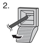
- Cleaning — Unplug the power cord from the AC outlet before cleaning the product. Use a dry cloth to clean the product. Do not use liquid cleaners or aerosol cleaners.
- Attachments — Do not use attachments not recommended by the manufacturer. Use of inadequate attachments can result in accidents.
- Water and moisture — Do not use the product near water, such as bathtub, washbasin, kitchen sink and laundry tub, swimming pool and in a wet basement.
- Ventilation — The vents and other openings in the cabinet are designed for ventilation. Do not cover or block these vents and openings since insufficient ventilation can cause overheating and/or shorten the life of the product. Do not place the product on a bed, sofa, rug or other similar surface, since they can block ventilation openings. Do not place the product in an enclosed place such as a bookcase or rack, unless proper ventilation is provided or the manufacturer's instructions are followed.
- Power cord protection — The power cords must be routed properly to prevent people from stepping on them or objects from resting on them.
- The LCD panel used in this product is made of glass. Therefore, it can break when the product is dropped or applied with impact. Be careful not to be injured by broken glass pieces in case the LCD panel breaks.
- Overloading — Do not overload AC outlets or extension cords. Overloading can cause fire or electric shock.
- Entering of objects and liquids — Never insert an object into the product through vents or openings. High voltage flows in the product, and inserting an object can cause electric shock and/or short internal parts.
For the same reason, do not spill water or liquid on the product.
- Servicing — Do not attempt to service the product yourself. Removing covers can expose you to high voltage and other dangerous conditions. Request a qualified service person to perform servicing.
- Repair — If any of the following conditions occurs, unplug the power cord from the AC outlet, and request a qualified service person to perform repairs.
a. When the power cord or plug is damaged.
b. When a liquid was spilled on the product or when objects have fallen into the product.
c. When the product has been exposed to rain or water.
d. When the product does not operate properly as described in the operating instructions.
Do not touch the controls other than those described in the operating instructions. Improper adjustment of controls not described in the instructions can cause damage, which often requires extensive adjustment work by a qualified technician.
e. When the product has been dropped or damaged.
f. When the product displays an abnormal condition. Any noticeable abnormality in the product indicates that the product needs servicing.
- Replacement parts — In case the product needs replacement parts, make sure that the service person uses replacement parts specified by the manufacturer, or those with the same characteristics and performance as the original parts. Use of unauthorised parts can result in fire, electric shock and/or other danger.
- Safety checks — Upon completion of service or repair work, request the service technician to perform safety checks to ensure that the product is in proper operating condition.
- Wall mounting — When mounting the product on a wall, be sure to install the product according to the method recommended by the manufacturer.
- Heat sources — Keep the product away from heat sources such as radiators, heaters, stoves and other heat-generating products (including amplifiers).
- Usage of the monitor must not be accompanied by fatal risks or dangers that, could lead directly to death, personal injury, severe physical damage or other loss, including nuclear reaction control in nuclear facility, medical life support system, and missile launch control in weapon system.
WARNING:
This is a class A product. In a domestic environment this product may cause radio interference in which case the user may be required to take adequate measures.
WARNING:
To reduce the risk of fire or electric shock, do not expose this product to rain or moisture.
- The TFT colour LCD panel used in this monitor is made with the application of high precision technology. However, there may be minute points on the screen where pixels never light or are permanently lit. Also, if the screen is viewed from an acute angle there may be uneven colours or brightness. Please note that these are not malfunctions but common phenomena of LCDs and will not affect the performance of the monitor.
- Do not display a still picture for a long period, as this could cause a residual image.
- If the brightness is adjusted to the minimum setting, it may be difficult to see the screen.
- The quality of the video signal may influence the quality of the display. We recommend using an equipment able to perform high quality video signals.
- Never rub or tap the monitor with hard objects.
- Please understand that Sharp Corporation bears no responsibility for errors made during use by the customer or a third party, nor for any other malfunctions or damage to this product arising during use, except where indemnity liability is recognised under law.
- This monitor and its accessories may be upgraded without advance notice.
- Do not use the monitor where ventilation is poor, where there is a lot of dust, where humidity is high, or where the monitor may come into contact with oil or steam, as this could lead to fire.
- Ensure that the monitor does not come into contact with water or other fluids. Ensure that no objects such as paper clips or pins enter the monitor as this could lead to fire or electric shock.
- Do not place the monitor on top of unstable objects or in unsafe places. Do not allow the monitor to receive strong shocks or to strongly vibrate. Causing the monitor to fall or topple over may damage it.
- Do not use in places where the monitor will be subject to direct sunlight, near heating equipment or anywhere else where there is likelihood of high temperature, as this may lead to generation of excessive heat and outbreak of fire.
The Power Cord
- Do not damage the power cord nor place heavy objects on it, stretch it or over bend it. Also, do not add extension cords. Damage to the cord may result in fire or electric shock.
- Use only the power cord supplied with the monitor.
- Insert the power plug directly into the AC outlet. Adding an extension cord may lead to fire as a result of overheating.
- Do not remove or insert the power plug with wet hands. Doing so could result in electric shock.
- Unplug the power cord if it is not used for a long time.
- Do not attempt to repair the power cord if it is broken or malfunctioning. Refer the servicing to the service representative.
Manual Scope
- In this manual, Microsoft Windows XP will be referred to as "Windows XP", and Microsoft Windows 2000 as "Windows 2000". When there is no need to distinguish between programmes, the term "Windows" will be used.
- Microsoft and Windows are registered trademarks of Microsoft Corporation.
- All other brand and product names are trademarks or registered trademarks of their respective holders.
- Language of OSD menu used in this manual is English by way of example.
- Illustrations in this manual may not exactly represent the actual product or display.
Fluorescent Tubes
- The fluorescent tubes in this product have a limited lifetime.
- Because of the property of fluorescent tubes, the screen may flash during the initial period of use. If this happens, please turn off the main power switch on the rear of the monitor and turn on again to confirm operation.
Introduction
IMPORTANT INFORMATION 1
DEAR SHARP CUSTOMER 3
SAFETY PRECAUTIONS 3
TIPS AND SAFETY INSTRUCTIONS 5
Supplied Accessories 7
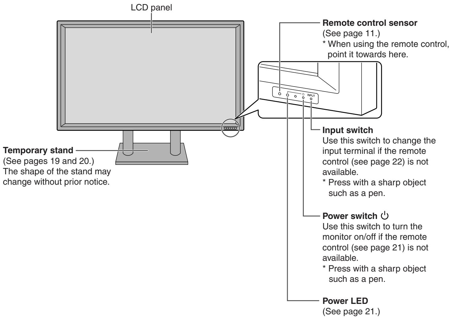
Part Names - Display 8
Front view 8
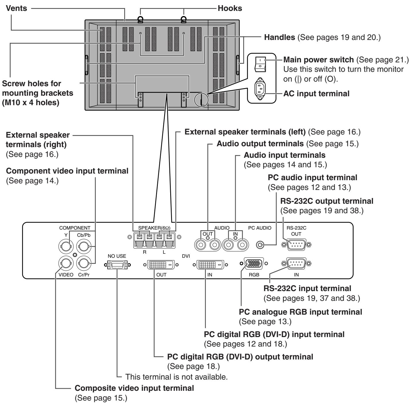
Rear view 9
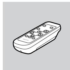
Part Names - Remote Control Unit 10
Opening the battery cover / Setting batteries 11
Remote control operation range 11
Connection and Installation
Connecting Peripheral Equipment 12
Connecting External Speakers 16
Connecting the Power Cord 17
Connecting Multiple Monitors 18
Mounting Precautions 19
Removing the Temporary Stand 20
Basic Operation
Turning Power On/Off 21
Main power switch 21
Turning power on/off using remote control 21
Remote Control Unit 22
Menu Items 23
Menu option selection 23
Menu screen explanation 25
Initialisation (Reset)/Functional Restriction Setting 26
Settings and Adjustments 27
Adjustments for PC screen display (ANALOG) 35
Set-up information 36
PC Operation
PC Operation 37
PC connection 37
Communication conditions 38
Communication procedure 39
RS-232C command table 46
Troubleshooting and Specifications
Troubleshooting 52
Specifications 54
Appendix
PC Digital/Analogue Signal Input Compatibility Chart 56
Terminal Compatibility Charts 57
Dimensional Drawings 58
Menu Option Reference Chart 59
Make sure the following accessories are provided with the product. If any component should be missing, please contact your dealer.
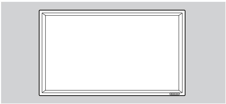
Liquid Crystal Display (1)
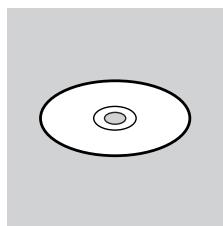
CD-ROM (1)
(Utility Disk for Windows)
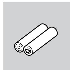
R-6 battery (2)
Remote control unit (1)
Power cord (1)
- Temporary stand (fixed) (1) (See pages 8 and 19.)
- Operation manual (1) - Stand hole protection cover (2)

- Sharp Corporation holds authorship rights to the Utility Disk programme. Do not reproduce it without permission.
- For environmental protection! Do not dispose of batteries in household garbage. Follow the disposal instructions for your area.
Front view
Relationship between the input signals and input terminals
You can use the remote control to change the input terminals used for video and audio signals. (See page 22.)
| Input mode (See page 25.) | Video input | Audio input |
| DIGITAL | PC digital RGB input terminal | PC audio input terminal |
| ANALOG | PC analogue RGB input terminal | PC audio input terminal |
| COMPONENT | Component video input terminal | Audio input terminals |
| VIDEO | Composite video input terminal | Audio input terminals |
Rear view
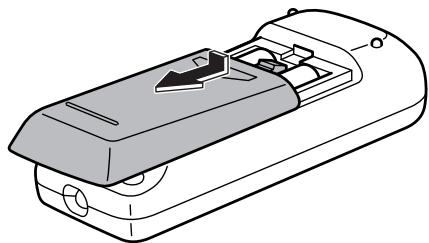
* The battery cover is located at the rear (underside) of the remote control unit.
Opening the battery cover/Setting batteries
- Press the cover gently and slide it in the direction of the arrow.
- See the instructions in the compartment and put in the supplied batteries (2 R-6 batteries) with their plus (+) and minus (-) sides oriented correctly.
- Close the cover.
Cautions regarding remote control unit
- Do not expose the remote control unit to shock by dropping or stepping on it. This could lead to a malfunction.
- Do not expose the remote control unit to liquids, and do not place it in an area with high humidity.

- The supplied batteries (2 R-6 batteries) may become exhausted faster depending on the storage condition. It is recommended that you replace them with new batteries (commercially available) earlier than specified.
- If you will not use the remote control for a long time, remove the batteries.
- If the remote control does not work, even with new batteries, take the batteries out, check whether they are facing the right way, then replace them.
- Do not use rechargeable (Nickel-metal-hydride) batteries.
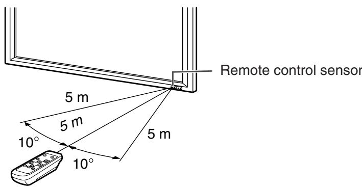
Remote control operation range
Operation range of the remote control unit is approx. 5m and an angle of approx. 10^ from the centre to the top/bottom/right/left of the remote control sensor.
If the remote control unit does not work well:
- The remote control unit may not work properly if the remote control sensor is under direct sunlight or strong lighting. In such cases, change the angle of the lighting, or operate the remote control unit closer to the remote control sensor.
- Objects between the remote control unit and the remote control sensor may prevent proper operation.
- Replace the batteries when they run low as this may shorten the remote control's operation range.
- If a fluorescent light is illuminated near the remote control unit, it may interfere with proper operation.
- Do not use it with the remote control of other equipment such as air conditioner, stereo components, etc.
Connecting Peripheral Equipment
This section describes the terminals of the monitor.

Be sure to set the main power switch to "OFF (O)" (see page 21) and disconnect the plug from the power outlet (see page 17) before connecting or disconnecting the cables.
Digital connection with a PC (Input mode: DIGITAL)
A PC image can be displayed using the PC digital RGB (DVI-D) input terminal.
- Connect to the digital RGB output terminal on your PC using a digital signal (DVI) cable (commercially available).
- Connection with computers that have an output terminal (DVI-D 24 pin or DVI-I 29 pin) conforming to DVI is possible. (However, images may not display properly depending on the computer.)
- Connect with an audio output terminal on your computer using a PC audio cable (commercially available).
- Select the input mode "DIGITAL" for this connection. (See page 22.)
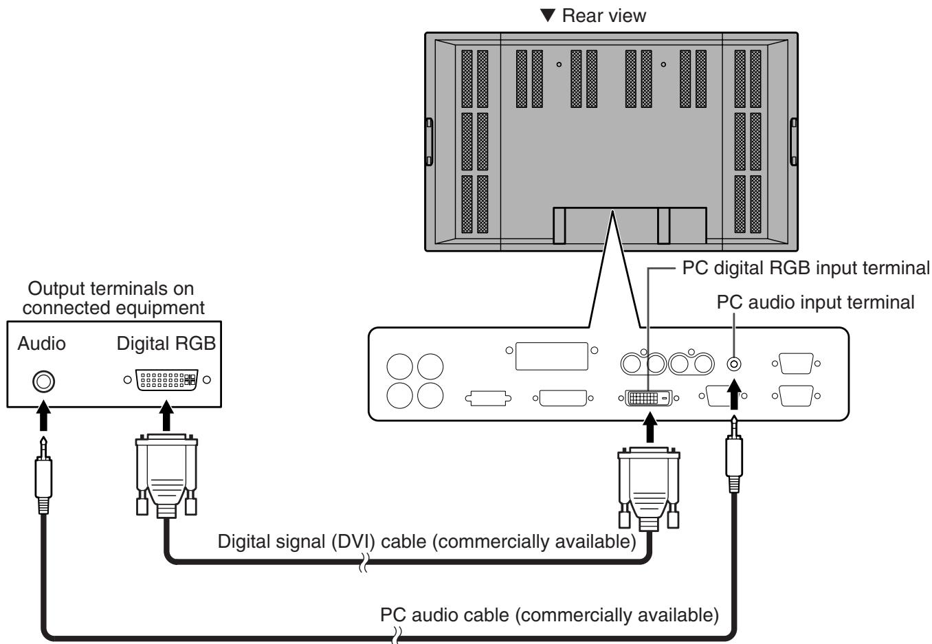

- See page 56 for compatible signal timing.
Analogue connection with a PC (Input mode: ANALOG)
A PC image can be displayed using the PC analogue RGB input terminal.
- Connect to the display (analogue RGB) output terminal on your PC using a PC analogue signal (RGB) cable (commercially available).
- Connect with an audio output terminal on your computer using a PC audio cable (commercially available).
- Select the input mode "ANALOG" for this connection. (See page 22.)
- Use the automatic screen adjustment when you use this connection to display a PC screen for the first time or when you change the setting of the PC. (See page 35.)
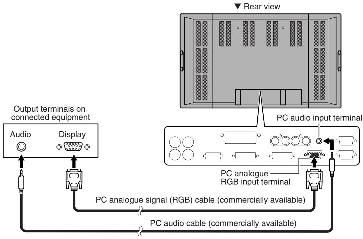

- Auto-detects sync signal type.
- Sync signal presence is detected in this order: Composite sync, Horizontal/Vertical separate, and Sync-on-green. If for some reason both Composite sync and Horizontal/Vertical separate are not input, the system will operate assuming that the signal is a Sync-on-green (i.e. that the sync signal is contained in the G signal of RGB). With some types of video signal, this may result in an unstable image.
- See page 56 for compatible signal timing.
Connecting Peripheral Equipment (Continued)
Connection with AV equipment (Input mode: COMPONENT)
- Connect to equipment that has a component video output terminal using a component (BNC) cable (commercially available).
- Connect with audio output terminals using an audio (RCA) cable (commercially available).
- Select the input mode "COMPONENT" for this connection. (See page 22.)
Connection with AV equipment (Input mode:VIDEO)
- Connect to equipment that has a video output terminal using a video (BNC) cable (commercially available).
- Connect with audio output terminals using an audio (RCA) cable (commercially available).
- Select the input mode "VIDEO" for this connection. (See page 22.)
Audio output terminals (See page 9.)
- Audio from the equipment connected to the audio input terminals or PC audio input terminal is output. Connect to the audio input terminals of the connected equipment using an audio (RCA) cable (commercially available) or a PC audio cable (commercially available).
- The audio output varies depending on the input mode selection: When the input mode is "DIGITAL" or "ANALOG", the audio from the PC audio input terminal is output.
When the input mode is "COMPONENT" or "VIDEO", the audio from the audio input terminals is output.
- The output volume is set to the value controlled with the volume adjustment. (See page 22.)
PC digital RGB (DVI-D) output terminal (See page 9.)
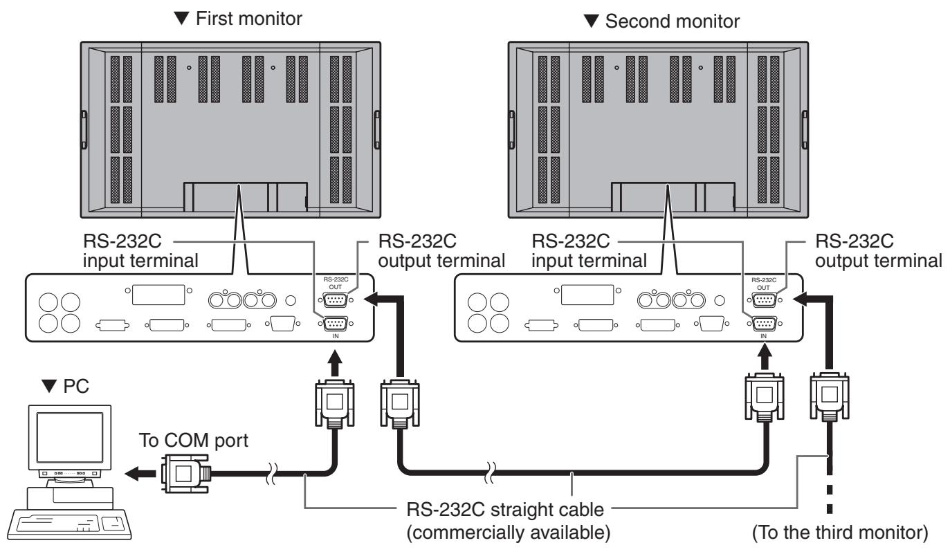
The video from the PC digital RGB (DVI-D) input terminal can be output to external equipment. Use this terminal to connect multiple units in a daisy chain using digital signal (DVI) cables (commercially available). Refer to page 18 for a connection example.
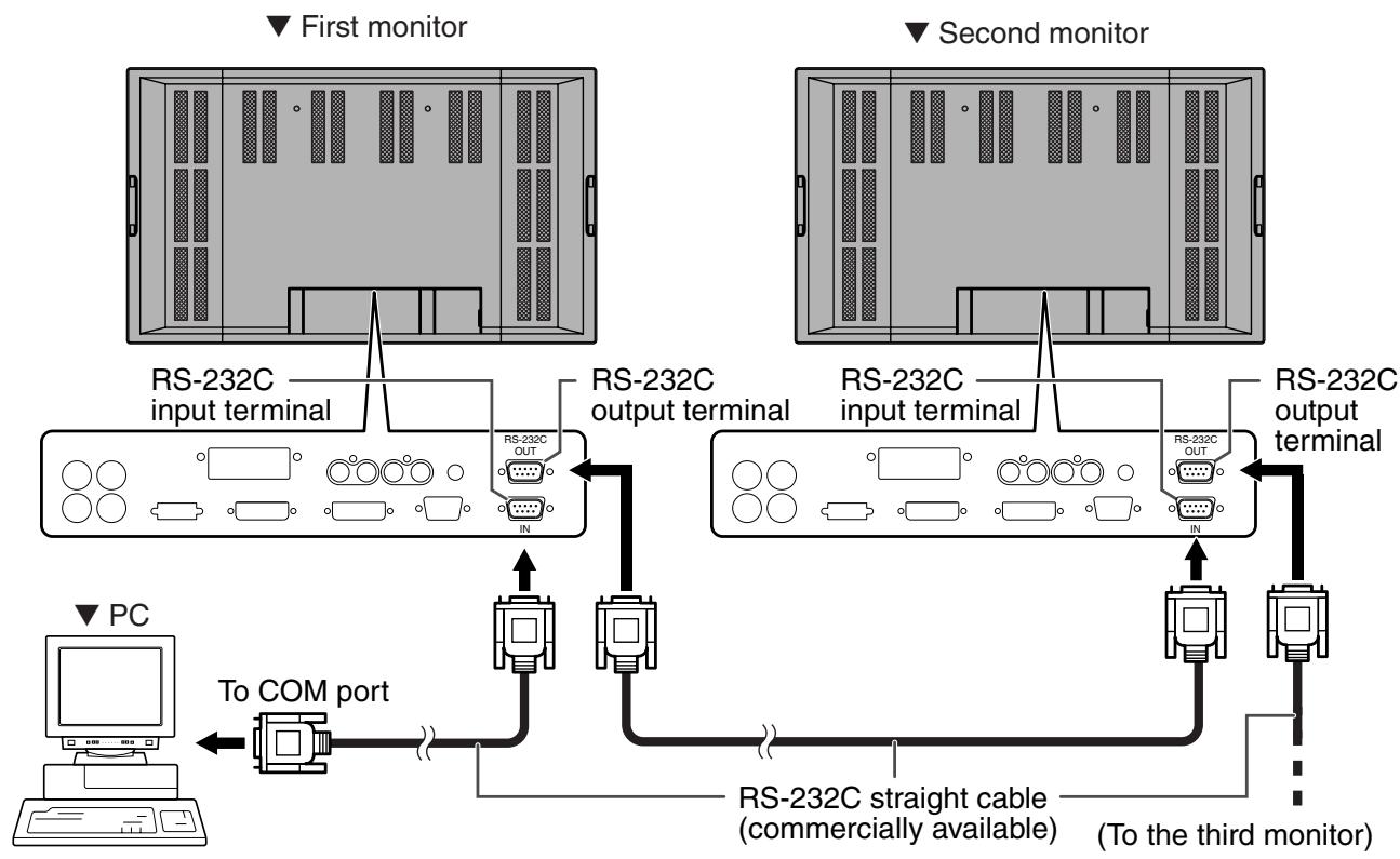
RS-232C input/output terminals (See page 9.)
Use these terminals to connect to a PC using an RS-232C straight cable(s) (commercially available) and to control a monitor (or monitors) externally. For connection examples and more information, refer to pages 19, 37, and 38.
Connecting External Speakers
Be sure to use external speakers with an impedance of 6 ohms and a rated input of at least 10 W.
Connecting the speaker cables
- While pushing the tab, insert the tip of the cable.
- Release the tab.
Make sure to connect the speaker terminal and cable polarity ( ,) properly.
The speaker terminals have plus and minus polarity. Plus is red and minus is black.
The speaker cables are also divided into plus and minus.
When connecting the left/right speakers, be sure to connect the plus/minus terminals with the correct cables.
Connecting the Power Cord
Connecting the power cord
- Be sure to set the main power switch to "OFF (O)" (see page 21) before connecting or disconnecting the power cord.
Do not use a power cord other than the one supplied with the monitor.
- Confirm that the main power switch is set to "OFF (O)".
- Plug the power cord (supplied) into the AC input terminal.
- Plug the power cord (supplied) into the AC power outlet.
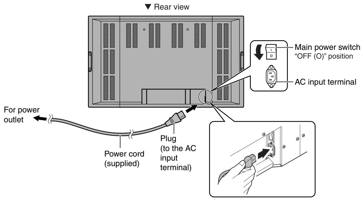
Disconnecting the power cord
- Confirm that the main power switch is set to "OFF (O)".
- Unplug the power cord from the AC power outlet.
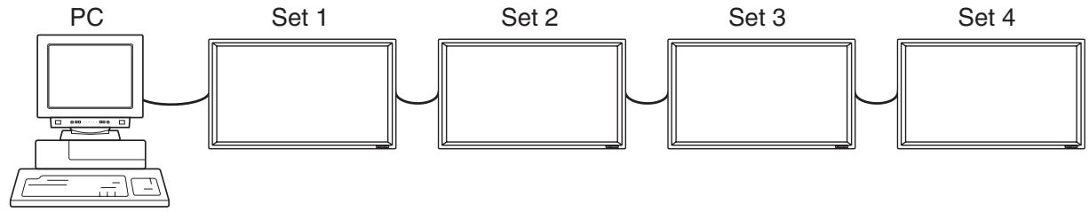
Connecting Multiple Monitors
Multiple monitors (4 units max.) can be connected in a daisy chain using the provided PC digital RGB input terminal and PC digital RGB output terminal.
Connection example
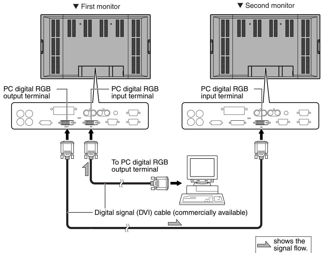

- Multiple monitors cannot be connected in a daisy chain for audio. Connect the external audio amplifier (commercially available) to the audio output terminals.
- The length of the digital signal (DVI) cables or surrounding environment may affect the image quality.
Connection example for RS-232C
Monitors can be externally controlled using the RS-232C interface (COM port) of a PC, and, in this case too, multiple monitors can be connected in a daisy chain. By assigning each monitor an ID number (see page 40), you can perform input mode selection, adjustment and status monitoring of individual monitors.
Mounting Precautions
- Since this product is heavy in weight, consult your dealer before installation.
- The monitor must be installed or moved by two or more people.
- When moving the monitor, be sure to hold it with the handles both on the rear and the unit bottom.
- Do not touch the LCD panel when moving the monitor. This may lead to breakage, malfunction or injury.
- Mount the monitor vertical to a level surface. Limit the tilting angle between 0^ and 20^ downward.
- Due to the monitors size and weight special techniques are required to mount the monitor. This monitor should only be mounted by qualified personnel using the correctly specified brackets and fittings, after mounting appropriate safety checks should be carried out and documented. You should never perform any of this work yourself. Our company will bear no responsibility for accidents or injuries caused by improper mounting or handling.
- This monitor is fixed to the temporary stand when shipped from the factory. Please note that this stand is for temporary use only until the monitor is properly mounted.
- Do not lay the monitor display-side down or up as this could lead to a malfunction.
- When mounting the monitor, the following amount of open space is required to clear the ventilation for the monitor; at least 30~cm above, 5cm right/left/below, and 3.5cm behind the monitor. Do not block any ventilation openings. If the temperature inside the monitor rises, this could lead to a malfunction.
- After mounting the monitor, it is recommended that you take measures against it possibly falling to the ground. Use commercially-available strong cord and metal fittings (hooks, etc.) to secure the hooks on the top of the monitor to a wall or pillar. (See page 9.)
- The mount bracket must be installed on the wall, which withstands at least 4 times (approx. 260kg ) weight of the monitor.
Removing the Temporary Stand
Follow the procedure below to remove the temporary stand.

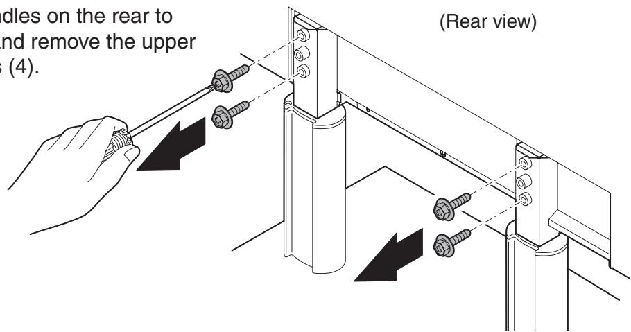
- Before removing the temporary stand, prepare wall-hanging brackets to mount the monitor unit. Read the manual of the brackets or stand for their mounting procedure. (The screw holes for mounting brackets (M10 × 4 holes) are provided on the rear of the monitor. (See page 9.))
-
The monitor must be installed or moved by two or more people.
-
Hold the monitor with the handles on the rear to prevent it from falling down, and remove the upper and lower stand fixing screws (4).
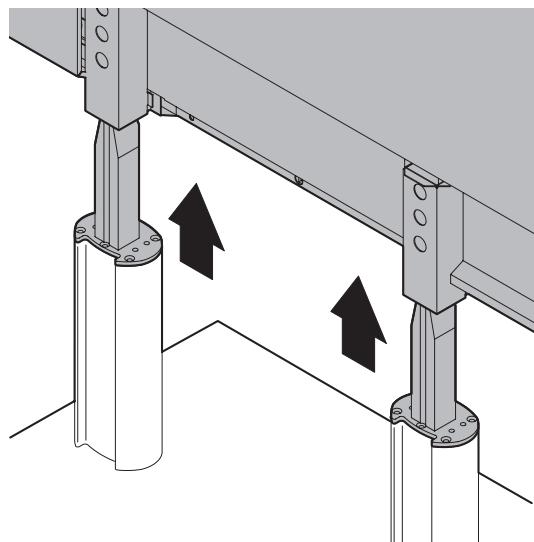
- Lift the monitor by holding it with the handles and the underside of the unit.
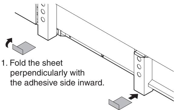
- When the installation is complete, attach the supplied stand hole protection covers as necessary.
-
Remove the adhesive cover and attach the sheet to the monitor.
-
The temporary stand is specifically designed for this monitor. Do not use the removed stand for other devices.
- Store the removed screws together with the stand. You must use the original screws when you mount the monitor onto the stand again. Using other screws could lead to a malfunction.
Turning Power On/Off
Before turning on power, make sure that peripherals, external speakers, and the power cord are connected properly.
There are two power supply switches: The main power switch on the rear of the monitor, and the POWER button on the remote control unit.

If the monitor is connected to a PC or a playback device, turn on the monitor first before turning on the PC or playback device.
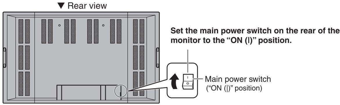
Main power switch
When the main power switch is off, the monitor is not turned on with the POWER button on the remote control unit.
Turning power on/off using remote control
Remote control unit

When switching the main power switch or the POWER button off and back on, always wait for at least 5 seconds. Rapid switching may result in a malfunction.

- When the input mode (see page 22) is set to "DIGITAL" or "ANALOG" and there is no video signal input, the backlight of the monitor is turned off and the monitor enters input signal waiting mode. (The power LED flashes green.) If the monitor is in this mode and you press the POWER button on the remote control unit, the monitor enters standby mode.
- If the remote control is not available, you can turn on/off by pressing the power switch beside the power LED with a sharp object (see page 8).
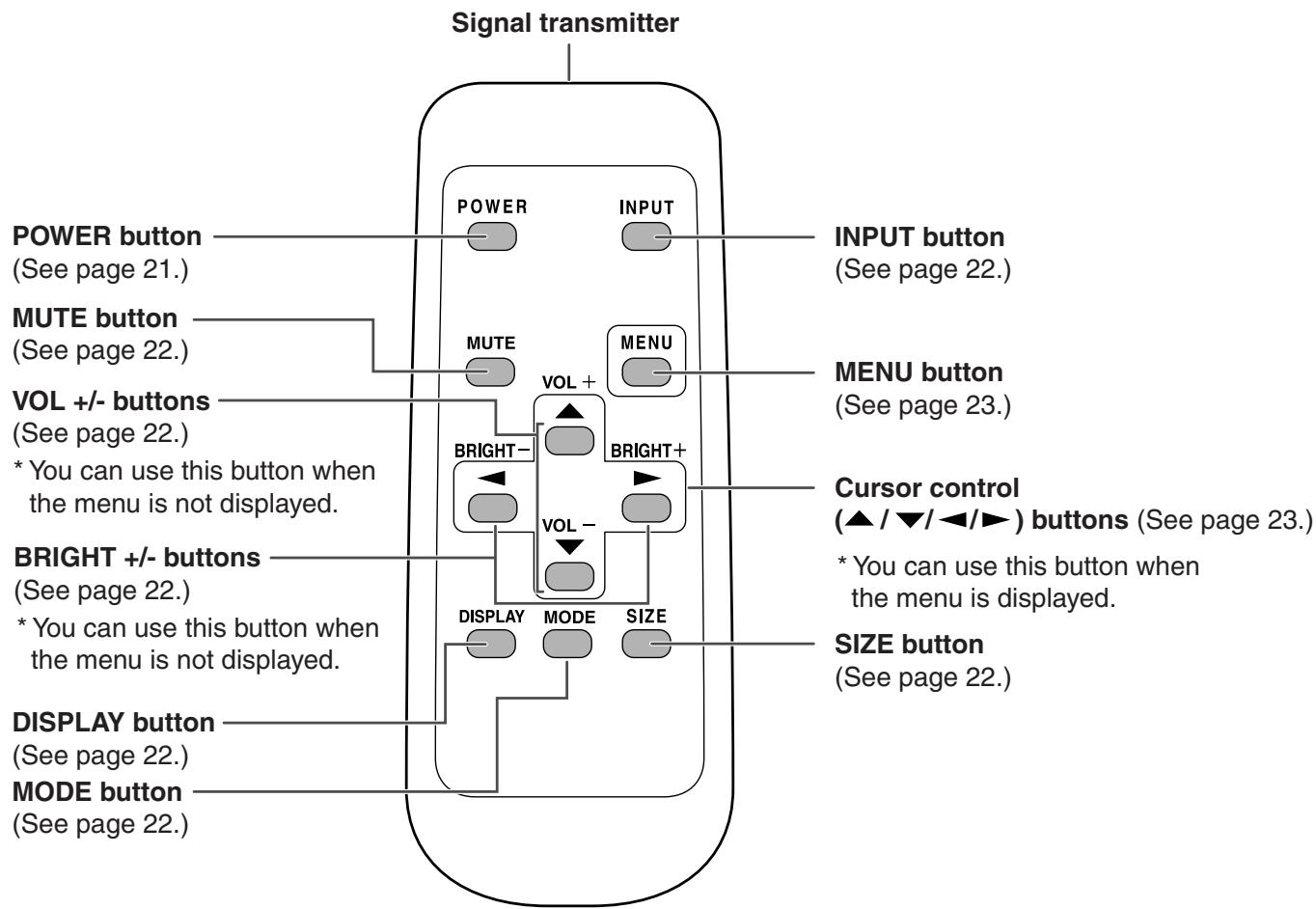
Remote Control Unit
Generally the monitor is operated using the remote control unit.
POWER
Turns on/off the power of the monitor (see page 21).
INPUT (Input mode selection)
Each time you press this button, the mode changes in the following order (see page 8):
- DIGITAL ANALOG COMPONENT VIDEO DIGITAL...
- If the remote control is not available, you can change the mode by pressing the input switch on the front panel of the monitor with a sharp object (see page 8).
MUTE
Turns off the volume temporarily.
Press the MUTE button again to turn the sound back to the previous level.
MENU
Displays and turns off the menu screen (see page 23).
VOL +/- (Volume adjustment)
Pressing or displays the VOLUME menu when the menu screen is not displayed.
VOLUME
15

Press to increase the volume, and to decrease the volume.
- If you do not press any buttons for about 4 seconds, the VOLUME menu automatically disappears.
Sound is muted when volume is set to "0".
BRIGHT +/- (Backlight adjustment)
Pressing or displays the BRIGHT menu when the menu screen is not displayed.
BRIGHT
15

Press to increase the brightness of the screen, and to decrease the brightness of the screen.
- If you do not press any buttons for about 4 seconds, the BRIGHT menu automatically disappears.
SIZE (Screen size selection)
Each time you press this button, the screen size changes in the following order (see page 34):
- WIDE ZOOM 1 ZOOM 2 NORMAL DotbyDot WIDE...
MODE (Screen mode selection)
Each time you press this button, the screen mode changes in the following order:
- STD (Standard) OFFICE* VIVID STD...
- Display brightness is lowered. (This mode saves power.)
DISPLAY
Displays monitor status such as SIZE (screen size), MODE (screen mode), BRIGHT ( backlight adjustment), VOLUME, ID No., model name, serial No. and so on. The display disappears when you press this button again, or it disappears automatically after approximately 4 seconds.
Menu Items
Menu can be displayed on the screen to enable video and audio adjustment and the setting of various functions using the remote control unit. For more information, refer to the pages where each topic is explained.
Menu option selection
Example of menu operation: Adjusting OSD H-POSITION in the MODE SELECT 2 menu.
1. Press MENU to display the menu screen.
(Example: When the input mode "DIGITAL" is selected)
- Press MENU twice to display the MODE SELECT 2 menu.
- Press to select OSD H-POSITION.
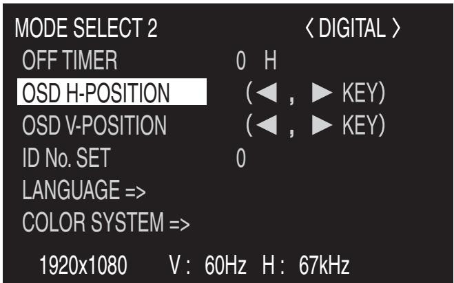
- Press (or ) to adjust the setting.
- Press MENU twice to close the menu screen.
The menu screen will close automatically if no operation is performed for about 15 seconds.

- The menu displayed when you press MENU will differ depending on the input mode selection. (See pages 59 to 61.)
Menu screen explanation
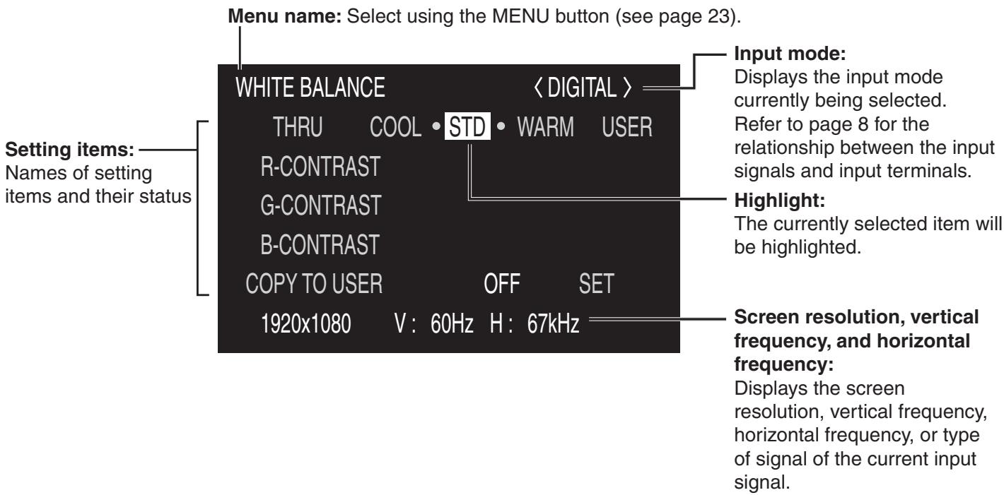
Yellow: Current setting
Blue: Selectable items
Grey: Items that cannot be selected
-
There are various reasons why items cannot be selected, but the main reasons are as follows:
-
There is no signal.
- The function is not compatible with the current input signal.
Menu screen duration
The menu screen will revert to the normal screen if there is no operation for about 15 seconds while the menu screen is displayed.

- The menu item illustrations in this operation manual are for explanation purposes only and may vary slightly from what is actually displayed.
Initialisation (Reset)/Functional Restriction Setting
You can return contrast, image quality, and other settings to their factory-preset values, specify whether power LEDs lights, and enable control via RS-232C (see page 37) among other functions.
1. After pressing SIZE for about 5 seconds, press , , , and in that order.
The FUNCTION 1 screen will appear.
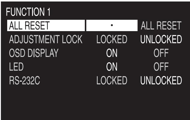
2. Select and set the items you want.
| [ALL RESET] | |
| Function | Reset all settings of the monitor to their factory preset values. After initialisation (reset), turn the main power switch off and then back on. |
| [ADJUSTMENT LOCK] | |
| Function | Specifies whether to lock settings such as ADJUSTMENT and WHITE BALANCE. While locked, the remote control unit cannot perform operations other than turning power on/off (POWER button) and displaying the FUNCTION 1 screen. |
| Default | UNLOCKED |
| LOCKED | Locks the setting. |
| UNLOCKED | Unlocks the setting. |
| [OSD DISPLAY] | |
| Function | Hides/shows menus. The FUNCTION 1 screen cannot be hidden. |
| Default | ON |
| ON | Displays the menus. |
| OFF | Hides the menus. |
| [LED] | |
| Function | Specifies whether to light power LEDs. |
| Default | ON |
| ON | Lights power LEDs. |
| OFF | Does not light power LEDs. |
| [RS-232C] | |
| Function | Specifies whether to allow control via RS-232C (see page 37). |
| Default | UNLOCKED |
| LOCKED | Disables control via RS-232C. |
| UNLOCKED | Enables control via RS-232C. |
3. Press to return to the normal screen.
Settings and Adjustments
The menu will differ depending on the input mode. For the menu items displayed for each input mode, refer to pages 59 to 61.
ADJUSTMENT (ANALOG)
| [MANUAL / AUTO] | |
| Function | Adjusts CLOCK, PHASE, H-POS (horizontal positioning), and V-POS (vertical positioning). |
| Adjustable range | MANUAL/AUTO |
| MANUAL | The CLOCK, PHASE, H-POS, and V-POS are manually adjusted. You can use the adjustment pattern on the supplied CD-ROM to adjust each parameter. For more information, refer to “Adjustments for PC screen display” on page 35. |
| AUTO | The CLOCK, PHASE, H-POS, and V-POS are automatically adjusted. Use this automatic adjustment when you use the PC analogue RGB input terminal to display a PC screen for the first time or when you change the setting of the PC. (See page 35.) |
| [MANUAL (CLOCK)] | |
| Function | Adjusts frequency for sampling clock for applicable video. Adjust when there is flickering in the form of vertical stripes. When using the adjustment pattern (see page 35), make adjustments so that no vertical stripe noise appears in it. |
| Adjustable range | 0 - 255 |
| + direction | Clock frequency increases. |
| - direction | Clock frequency decreases. |
| [MANUAL (PHASE)] | |
| Function | Adjusts sampling clock phase for applicable video. Useful when small characters appear with low contrast and/or there are flickers at corners. When using the adjustment pattern (see page 35), make adjustments so that no horizontal stripe noise appears in it. |
| Adjustable range | 0 - 255 |
| + direction | Advances clock phase. |
| - direction | Delays clock phase. |
| [MANUAL (H-POS)] | |
| Adjustable range | 0 - 255 |
| + direction | Image shifts right. |
| - direction | Image shifts left. |
| [MANUAL (V-POS)] | |
| Adjustable range | 0 - 255 |
| + direction | Image shifts up. |
| - direction | Image shifts down. |
| [RESET] | |
| Adjustable range | / RESET |
| RESET | Reset the values of the ADJUSTMENT menu items to the factory preset values. When □ is pressed, the values are reset (initialised). |
Settings and Adjustments (Continued)
■ GAIN CONTROL (ANALOG)
| [MMANUAL / AUTO] | |
| Function | Adjusts BLACK LEVEL and CONTRAST. |
| Adjustable range | MANUAL / AUTO |
| MANUAL | The BLACK LEVEL and CONTRAST can be adjusted manually by checking the adjustment pattern. (See page 35.) |
| AUTO | The BLACK LEVEL and CONTRAST are automatically adjusted. |
| [MMANUAL (BLACK LEVEL)] | |
| Adjustable range | 0 - 31 |
| Default | 15 |
| + direction | Brightens entire video signal. |
| - direction | Darkens entire video signal. |
| [MMANUAL (CONTRAST)] | |
| Adjustable range | 0 - 31 |
| Default | 15 |
| + direction | For more contrast |
| - direction | For less contrast |
■ WHITE BALANCE (DIGITAL/ANALOG)
| [THRU / COOL / • / STD / • / WARM / USER] | |
| Adjustable range | THRU / COOL / • / STD / • / WARM / USER |
| Default | STD |
| THRU | Displays the input signal level as it is. This item is only selectable for DIGITAL. |
| COOL | Colour tone bluer than standard |
| • | Colour tone slightly bluer than standard |
| STD | Colour tone standard setting |
| • | Colour tone slightly redder than standard |
| WARM | Colour tone redder than standard |
| USER | Allows you to individually adjust R-CONTRAST, G-CONTRAST, and B-CONTRAST. |
| [COPY TO USER] | |
| Adjustable range | OFF / SET |
| SET | Copies the values set for COOL / • / STD / • / WARM to USER settings. |
| [USER (R-CONTRAST)] | |
| Adjustable range | 0 - 255 |
| + direction | Brightens red component. |
| - direction | Darkens red component. |
| [USER (G-CONTRAST)] | |
| Adjustable range | 0 - 255 |
| + direction | Brightens green component. |
| - direction | Darkens green component. |
| [USER (B-CONTRAST)] | |
| Adjustable range | 0 - 255 |
| + direction | Brightens blue component. |
| - direction | Darkens blue component. |
VIDEO ADJUSTMENT (COMPONENT/VIDEO)
| [CONTRAST] | |
| Adjustable range | 0 - 31 |
| Default | 15 |
| + direction | For more contrast |
| - direction | For less contrast |
| [BLACK LEVEL] | |
| Adjustable range | 0 - 31 |
| Default | 15 |
| + direction | Brightens entire video signal. |
| - direction | Darkens entire video signal. |
| [TINT] | |
| Adjustable range | 0 - 31 |
| Default | 15 |
| + direction | Adjust the hue in the required direction so that the colour takes on a green tinge. |
| - direction | Adjust the hue in the required direction so that the colour takes on a magenta tinge. |
| [COLORS] | |
| Adjustable range | 0 - 31 |
| Default | 15 |
| + direction | For more colour intensity |
| - direction | For less colour intensity (Monochrome at “0”) |
| [SHARPNESS] | |
| Adjustable range | 0 - 31 |
| Default | 15 |
| + direction | For more sharpness |
| - direction | For less sharpness |
| [WHITE BALANCE] | |
| Adjustable range | COOL / • / STD / • / WARM |
| Default | STD |
| COOL | Colour tone bluer than standard |
| • | Colour tone slightly bluer than standard |
| STD | Colour tone standard setting |
| • | Colour tone slightly redder than standard |
| WARM | Colour tone redder than standard |
Settings and Adjustments (Continued)
MODE SELECT 1
| [480 LINES] (ANALOG) | |
| Function | Manually selects input resolution. |
| Adjustable range | 848 / 640 |
| Default | 640 |
| [768 LINES] (ANALOG) | |
| Function | Manually selects input resolution. |
| Adjustable range | 1360 / 1280 / 1024 |
| Default | 1024 |
| [BEZEL] (DIGITAL/ANALOG) | |
| Function | Sets the frame width of the LCD panel (V: Vertical width, H: Horizontal width) when the enlargement function is used. |
| Adjustable range | 0 - 100 |
| Default | 50 |
| [ENLARGE] (DIGITAL/ANALOG) (See page 33) | |
| Function | Sets the image enlargement ratio to be enlarged. |
| Adjustable range | OFF / 2 x 2 / 3 x 3 / 4 x 4 |
| Default | OFF |
| [ENLARGE-POS] (DIGITAL/ANALOG) | |
| Function | Sets the part of the original image to be enlarged. |
| Adjustable range (2 x 2) | 0 - 3 |
| Adjustable range (3 x 3) | 0 - 8 |
| Adjustable range (4 x 4) | 0 - 15 |
| Default | 0 |
| [MULTI ZOOM] (DIGITAL/ANALOG) | |
| Function | Adjusts the enlarged screen. |
| Pressing ☐ displays the next menu. | |
| IMAGE ZOOM | Adjusts the scale of enlargement. |
| H-POS | Adjusts the horizontal position. |
| V-POS | Adjusts the vertical position. |
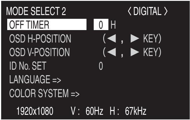
MODE SELECT 2
| [OFF TIMER] | |
| Function | Specifies the remaining time before turning off the power (entering standby mode) (see page 21). |
| Adjustable range | 0 - 23 (hours) |
| Default | 0 |
| [OSD H-POSITION] | |
| Function | Adjusts the horizontal display position of menu screen. |
| How to adjust | Use ▲ / ▲ to move menu screen. |
| Default | Centre |
| [OSD V-POSITION] | |
| Function | Adjusts the vertical display position of menu screen. |
| How to adjust | Use ▲ / ▲ to move menu screen. |
| Default | Centre |
| [ID No. SET] | |
| Function | Assigns ID numbers to monitors connected in a daisy chain (see page 38), using RS-232C cables. |
| Adjustable range | 0 - 255 |
| Default | 0 |
| Note | The numbers 1 to 255 are available for ID numbers. (If “0” is set, the system regards this as the state where no ID number is set.) Although numbers up to 255 can be used for monitor IDs, the number of connectable monitors varies depending on the length of RS-232C cables and the installation environment. Use ▲ / ▲ to increase or decrease values. |
| [LANGUAGE] | |
| Function | Switches the OSD language. |
| Available languages | ENGLISH / DEUTSCH / FRANÇAIS / ITALIANO / ESPÁÑOL |
| Default | ENGLISH |
| [COLOR SYSTEM] | |
| Function | Select the colour system of the AV equipment which is connected to the composite video input terminal. When AUTO is selected, the colour system is automatically set according to the input signal. |
| Available formats | AUTO / PAL / PAL-60 / SECAM / NTSC3.58 / NTSC4.43 |
| Default | AUTO |
Settings and Adjustments (Continued)
MODE SELECT 3
| [PIP MODES] (See page 33) | |
| Function | Sets the display method. |
| Adjustable range | OFF/PIP (Picture in Picture)/PbyP (Picture by Picture)/PbyP2 |
| Default | OFF |
| OFF | Displays one screen. |
| PIP | Displays a sub screen inside a main screen. |
| PbyP | Displays a main screen and a sub screen side by side. |
| PbyP2 | Displays a main screen which measures 1280 in width and a sub screen side by side. |
| [PIP SIZE] | |
| Function | Sets the size of the sub screen in PIP mode. |
| Adjustable range | SMALL/MEDIUM/LARGE |
| Default | SMALL |
| [PIP H-POS] | |
| Function | Adjusts the horizontal position of the sub screen in PIP mode. |
| Adjustable range | 0 - 100 |
| Default | 99 (Decreasing the value moves the sub screen to the left.) |
| [PIP V-POS] | |
| Function | Adjusts the vertical position of the sub screen in PIP mode. |
| Adjustable range | 0 - 100 |
| Default | 1 (Increasing the value moves the sub screen upward.) |
| [PIP BLEND] | |
| Function | Displays the sub screen transparently on the main screen in PIP mode. |
| Adjustable range | 0 - 15 |
| Default | 0 (Increasing the value makes the sub screen more transparent.) |
| [PIP SOURCE] | |
| Function | Selects the signal input of the sub screen in PIP (Picture in Picture), PbyP (Picture by Picture), or PbyP2 mode. |
| Adjustable range (PC) | DIGITAL/ANALOG |
| Adjustable range (AV) | COMPONENT/VIDEO |
| Default | DIGITAL(PC)/VIDEO(AV) |
| [SOUND CHANGE] | |
| Function | Outputs the specified sound in PIP, PbyP, or PbyP2 mode. |
| Adjustable range | If the main screen is displayed as a full screen by the AUTO OFF function, the sound for the main screen is output even when the sound for the sub screen is specified. |
| [MAIN POS] | |
| Function | Specifies whether to display the main screen on the right or left in PbyP or PbyP2 mode. |
| Adjustable range | LEFT/RIGHT |
| Default | LEFT |
| [PbyP2 POS] | |
| Function | Sets the vertical position of the sub screen in PbyP2 mode. |
| Adjustable range | TOP/CENTER/Bottom |
| Default | CENTER |
| [AUTO OFF] | |
| Function | Sets whether to display the main screen as a full screen in PIP, PbyP, or PbyP2 mode when there is no signal input for the sub screen. |
| Adjustable range | MANUAL/AUTO |
| Default | AUTO |
| AUTO | Displays the main screen as a full screen when there is no signal input for the sub screen. |
| MANUAL | Displays the sub screen in black when there is no signal input for the sub screen. |
Dual screen display
You can display the screens of the PC input signal (ANALOG/DIGITAL) and AV input signal (COMPONENT/VIDEO) simultaneously.
Set this function with "PIP MODES" in the MODE SELECT 3 menu. (See page 32.)
- The currently selected input signal is displayed on the main screen.
- You cannot simultaneously display the screens of signals of the same type, such as two types of PC input signals or two types of AV input signals. The screens of one of the PC input signals and one of the AV input signals can be displayed simultaneously.
| PIP | PbyP | PbyP2 | ||
| Example Main screen Sub screen A sub screen is displayed inside a main screen. | Example | Example Main screen | Sub screen | |
| Main screen | Sub screen | |||
| A main screen of 1280 width size and a sub screen are displayed side by side. | ||||
- If "COMPONENT" is selected for the main screen in PbyP mode and 1080i video signals are input, the image quality cannot be changed by adjusting the value of "SHARPNESS" from the VIDEO ADJUSTMENT menu.
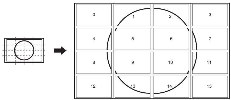
Enlarge
You can set up 4, 9, or 16 monitors and integrate them into a single large screen to display video. Each monitor displays an enlargement of 14 , 19 , or 116 of the original image.

- Using PC digital RGB input/output terminals, up to 4 monitors can be daisy-chained. (See page 18.)
-
To connect 9 or 16 monitors to integrate a screen, a separate video signal splitter (commercially available) is required.
-
4 screen monitor set-up
-
9 screen monitor set-up
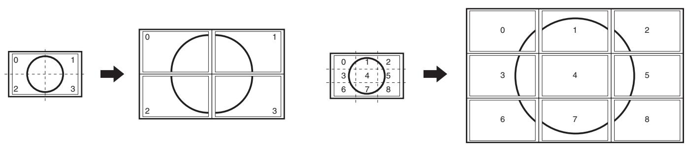
16 screen monitor set-up
Switching the screen size (When the input mode is DIGITAL/ANALOG)
Even when the screen size is changed, the display may remain the same depending on the input signal.
| WIDE | ZOOM 1 | ZOOM 2 |
| Displays image so it fills the entire screen. | Displays the image of the aspect ratio of 4:3 so it fills the entire screen with the same aspect ratio. The upper and lower portion of the image may be cut off. | Use this size if ZOOM 1 cuts off the subtitles. |
| NORMAL | DotbyDot | |
| Displays image so it fills the screen vertically, while maintaining the original aspect ratio. | Displays the dots of the signals input from the connected PC as the corresponding dots on the screen. (See page 56.) |
Switching the screen size (When the input mode is COMPONENT/VIDEO)
The desired screen size can be selected to suit the input signal.
Even when the screen size is changed, the display may remain the same depending on the input signal.
| WIDE | ZOOM 1 | ZOOM 2 |
| Displays the image of the aspect ratio of 4:3 so it fills the entire screen by stretching the image. | Displays the image of the aspect ratio of 4:3 so it fills the entire screen with the same aspect ratio. The upper and lower portion of the image may be cut off. | Use this size if ZOOM 1 cuts off the subtitles. |
| NORMAL | DotbyDot | |
| Displays the entire image of the aspect ratio of 4:3 without changing the aspect ratio. | Displays the dots of the input signals as the corresponding dots on the screen.* |
- If "DotbyDot" is selected when the VIDEO or COMPONENT (480i or 480p) image is displayed, the image quality cannot be changed by adjusting the value of "SHARPNESS" from the VIDEO ADJUSTMENT menu.

- Using this monitor's screen-size switching or dual-screen display functions to compress or expand the screen for commercial or public viewing in establishments like cafes or hotels may infringe on the rights of the creators, as protected by Copyright Law, so please be careful.
- When using the screen-size switching function of this monitor, the appearance of the original video may change if you select a screen size with a different aspect ratio than the original image (e.g. TV broadcast or video input from external equipment). Please consider this point when selecting the screen size.
- When an ordinary non-wide image (4:3) is viewed with the whole screen using the screen-size switching function of this monitor, the edge of the image may be lost or appear distorted. If you wish to respect the creator's intentions, set the screen size to "NORMAL".
- When playing commercial software, parts of the image (like subtitles) may be cropped. In this case select the optimal screen size using the screen-size switching function of this monitor. With some software, there may be noise or distortion at the edges or top of the screen. This is due to the characteristics of the software, and is not a malfunction.
- Depending on the original image size (e.g. CinemaScope size), black bands may remain at the top and bottom of the screen.
Adjustments for PC screen display (ANALOG)
When you use the PC analogue RGB input terminal to display a PC screen for the first time, or when you change the setting of the PC, you need to perform the automatic adjustment from the ADJUSTMENT menu. (See page 27.)
Before making adjustments in the ADJUSTMENT menu or GAIN CONTROL menu, display an image to brighten the entire screen.
If you are using a Windows PC, use the adjustment pattern on the supplied CD-ROM.
Retrieving the adjustment pattern
This explanation assumes you are using Windows 2000/XP.
- Connect the monitor and computer (see page 13).
- Load the supplied CD-ROM into the computer's CD-ROM drive.
- Open the CD-ROM in [My Computer].
- Double-click [Adj_uty.exe] to start the adjustment programme. The adjustment pattern will appear. Adjust the screen automatically or manually.
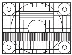
- When adjustment is finished, press the [Esc] on the computer's keyboard to quit the adjustment programme.

- If the display mode on the computer you are using is 65,000 colours, the colour levels in the colour pattern may appear differently or greyscale may appear to be coloured. (This is due to the specifications of the input signal and is not a malfunction.)
Automatic adjustment procedure
- Set the input mode to "ANALOG" and display the adjustment pattern above.
- Press MENU and display the ADJUSTMENT menu.
- Press and select "AUTO". The automatic adjustment is complete in several seconds.
- Press six times to close the menu screen.

- If the screen cannot be adjusted properly with one automatic adjustment, repeat the automatic adjustment two or three times. Try manual adjustment if necessary. (See page 27.)
Settings and Adjustments (Continued)
Set-up information
To install the set-up information on the connected PC, follow the steps below. (Depending on the type of computer or OS, command names and methods may differ. Please follow the computer's own operation manual while reading this.)
Installing set-up information
For Windows 2000
This explanation is for installing and setting monitor set-up information on a Windows 2000 computer, and it assumes your CD-ROM drive is the "D" drive.
- Connect the monitor and computer.
- Load the supplied CD-ROM into the computer's CD-ROM drive.
- Click the [Start] button. From [Settings], choose [Control Panel].
- Double-click [Display].
- Click [Settings], [Advanced], and [Monitor].
- Click [Properties], [Driver], and [Update Driver].
- When the [Upgrade Device Driver Wizard] appears, click [Next].
- Select [Display a list of the known drivers for this device so that I can choose a specific driver] and click [Next].
- When [Models] is displayed, click [Have disk], confirm that [Copy manufacturer's files from:] is [D:], and click [OK].
- Select the monitor from the list displayed and click [Next].
- Click [Next], confirm that the monitor's name appears on the screen, and click [Finish]. If [The Digital Signature Not Found] appears, click [Yes].
- Click [Close] to close [Display Properties].
- Click [OK] to close the window.
- Eject the CD-ROM from the CD-ROM drive.
For Windows XP
This explanation is for installing and setting monitor set-up information on a Windows XP computer, and it assumes your CD-ROM drive is the "D" drive.
- Connect the monitor and computer.
- Load the supplied CD-ROM into the computer's CD-ROM drive.
- Click the [Start] button. Choose [Control Panel].
- Click [Appearance and Themes] and [Display]. When using Classic View, double-click [Display].
- Click [Settings], [Advanced], and [Monitor].
- Click [Properties], [Driver], and [Update Driver]. The [Hardware Update Wizard] appears. When you are asked whether to search Windows Update for the device driver, select [No, not this time] and click [Next].
- Select [Install from a list or specific location] and click [Next].
- Select [Don't search. I will choose the driver to install.] and click [Next].
- Click [Have Disk], confirm that [Copy manufacturer's files from:] is [D:], and click [OK].
- Select the monitor from the list displayed and click [Next]. If [has not passed Windows Logo testing...] appears, click [Continue Anyway].
- Confirm that the monitor's name appears on the screen and click [Finish].
- Click [Close] to close [Screen Properties].
- Click [OK] to close the window.
- Eject the CD-ROM from the CD-ROM drive.
PC connection
1. One-to-one connection with a PC...... Basic operation
Connect with RS-232C straight cable between the PC COM port (RS-232C connector) and the RS-232C input terminal on the rear of monitor.
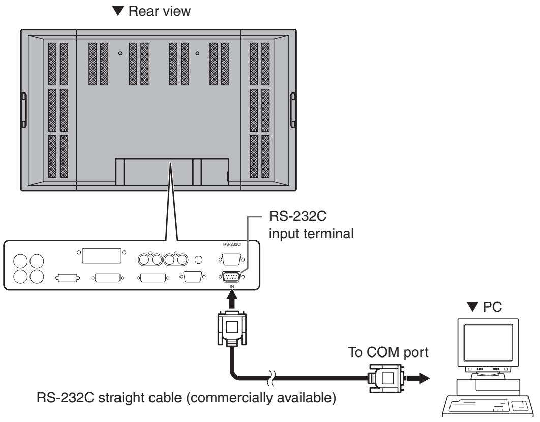
2. Daisy chain connection from a single PC..... Advanced operation
Connect with RS-232C straight cable between the PC COM port (RS-232C connector) and the RS-232C input terminal on the rear of monitor.
Next, connect RS-232C straight cable to the first monitor's RS-232C output terminal and to the second monitor's RS-232C input terminal. Connect in the same way to the third and subsequent monitors. The number of connectable monitors varies depending on the length of the cable used and the surrounding environment.
Communication conditions
Set the RS-232C communication settings on the PC to match the monitor's communication settings.
| Baud rate | 9,600 bps |
| Data length | 8 bits |
| Parity bit | None |
| Stop bit | 1 bit |
| Flow control | None |
Communication procedure
Basic operation
When a command is sent from the PC to the monitor, the monitor operates according to the received command, and sends a response message to the PC.
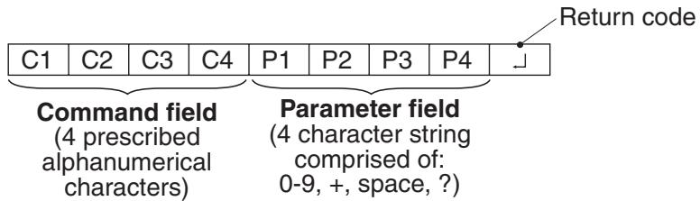
Example: VOLM0030
VOLM 30 (" ” indicates a space.)
- Be sure to input 4 characters for the parameter. Pad with spaces if necessary.
Wrong: VOLM30
Right: VOLM 30 ("□" indicates a space. "□" is the return code (ODH, OAH or ODH).)
If a command has "R" listed for "DIRECTION" in the "RS-232C command table" on page 46, the current value can be returned by using "?" as the parameter.
Example: 1. If an ID number has not been set:
VOLM????? From PC to monitor (How much is current volume setting?)
30 From monitor to PC (Current volume setting: 30)
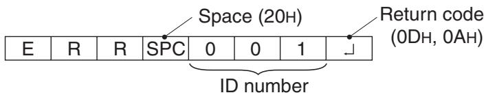
- If an ID number has been assigned (For example, ID number = 1)
VOLM ? From PC to monitor ("□" indicates a space.)
30 001 From monitor to PC ("□" indicates a space.)
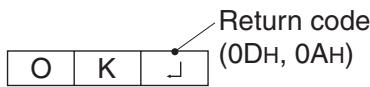
■ When a command has been executed correctly
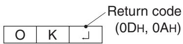
This is returned when execution of the command is finished.
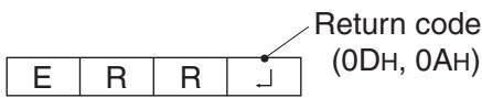
■ When a command has not been executed correctly*
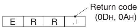
- This is returned when there is no such command, or when the command cannot be used in the current state of the monitor (Example: When "ADJUSTMENT" is used (a command which is effective when the input mode is "ANALOG"), while video is displayed (the input mode is "VIDEO").
- If there is a bad connection between the PC and monitor, or if communication has not been established, nothing is returned (not even ERR).
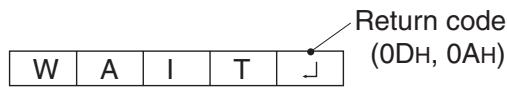
If execution of the command is taking some time

■ If RS-232C is locked
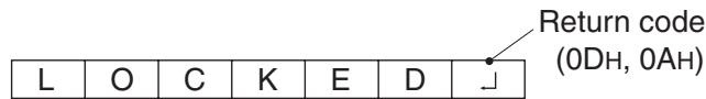
With some commands, "WAIT" is returned as a return value. Wait for a moment, and OK or ERR will be returned. New commands cannot be received during this time, even if they are sent.
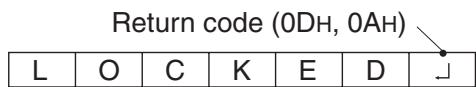
If RS-232C control has been locked with the operation lock (see page 26), LOCKED is returned as the returned value.
Advanced operation
This section explains commands for daisy chain connection. The basic communication procedure is the same as in the "Basic operation" section.
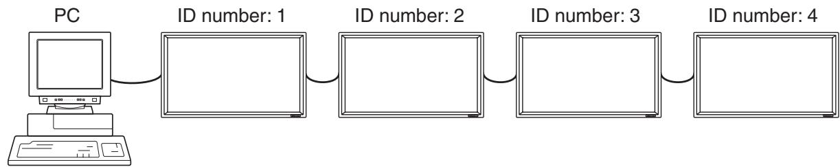
You can assign a unique ID number to each monitor (see page 31). This allows you to control a particular monitor in a daisy chain of monitors.
Up to about 20 monitors can be connected, depending on the length of RS-232C cables and installation environment.
You can assign ID numbers either from the menu screen (using the remote control) or from the PC using RS-232C cable.
[Example]
![SHARP PN-655E - [Example] - 1](/content/2025/01/122442/images/a4b96361de1b3d3026e72368f5d25578a664276fbbf4a923930cdd4222236c6c.jpg)
If monitors are connected as shown above, you can execute commands like "Set the volume of the monitor with ID 4 to 20".
When controlling monitors linked in a daisy chain by designating ID numbers, you should basically avoid any duplication of ID numbers.
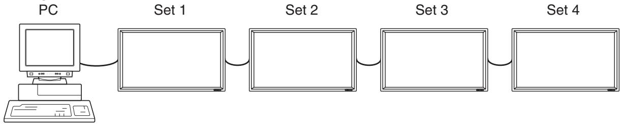
ID numbers do not have to be assigned in ascending order starting from the PC. They can also be connected as shown below.
[Example]
![SHARP PN-655E - [Example] - 1](/content/2025/01/122442/images/aedcaba6e76dc42da6a95cffdcd90df44bbeaddea205eb398b817519ccce41c4.jpg)
The command examples shown on this page assume the following connection and ID number set up.
![SHARP PN-655E - [Example] - 1](/content/2025/01/122442/images/1a8bf2f8b11b85b0f9100412ba3715fec08439338e6d478294496203f01893e3.jpg)
IDST......A monitor receiving this command sets its own ID number in the parameter field.
Example: IDST0001
OK 001 The ID number of this monitor is set to 1.
Note
After linking monitors, you can automatically assign ID numbers by using the IDST command with the Repeater control (see "Repeater control" on page 43).
[Example]
If you connect monitors as shown above, and use the command "IDST001+", ID numbers will be set automatically, as shown below.
[Example]
IDST001+ ID setting command with repeater control WAIT
OK 001 "OK" response from ID number: 1
OK 002 "OK" response from ID number: 2
OK 003 "OK" response from ID number: 3
OK 004 "OK" response from ID number: 4 (End)
IDSL...... The parameter of this command sets the ID number of the monitor. The monitor is subject to the next command.
Example
IDSL0002 ← The next command is for the monitor with ID number: 2.
WAIT Searching for monitor with ID number: 2
OK 002 ← Found monitor with ID number: 2
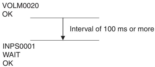
VOLM0030 Sets volume of monitor with ID number: 2 to 30.
WAIT Processing
OK 002 ← OK response from monitor with ID number: 2
VOLM0020 Sets volume to 20.
OK 001 The volume of the monitor with ID number: 1 (the one directly connected to the PC) is set to 20.
The IDSL command is effective only once, for the immediately succeeding command.
IDLK...... The parameter of this command sets the ID number of the monitor. The monitor is subject to all subsequent commands.
Example:
IDLK0002 Following commands are for the monitor with ID number: 2.
WAIT Searching for monitor with ID number: 2
OK□002 Found monitor with ID number: 2
VOLM0030 Sets volume of monitor with ID number: 2 to 30.
WAIT Processing
OK□002
VOLM0020 Sets volume of monitor with ID number: 2 to 20.
WAIT
OK,002
IDLK0000 ← Canceling fixed ID number setting
WAIT Canceling IDLK
OK□002 Cancelation complete
VOLM0010
OK□001 The volume of the monitor with ID number: 1 (the one directly connected to the PC) is set to 10.
The IDLK command remains effective until it is canceled, or power is shut off.
IDCK ....... Provides screen display of the ID number currently assigned to a monitor, and the ID number currently set for IDLK (if any).
Example:
(After executing IDLK0002)
IDCK0000 (Parameter has no meaning.)
ID:001 IDLK:002 Returned response. The ID number is also displayed on the monitor screen.
IDCK000+ Repeater control
(If a command is used with repeater control, ID designation using IDSL or IDLK is canceled.)
WAIT
ID:001 IDLK:002
ID:002 IDLK:002
ID:003 IDLK:002
ID:004 IDLK:002
This system has a function to allow setting of multiple monitors connected in a daisy chain using a single command. This function is called repeater control.
The number of connectable monitors varies depending on the length of the cable used and the surrounding environment.
You can use Repeater control function without assigning ID numbers.
[Example]
If monitors are connected as shown above, you can execute a command like "Set all monitors' input settings to INPUT1 (DVI: DIGITAL)".
Repeater control is achieved by setting the FOURTH CHARACTER of the parameter to "+".
Example:
VOLM030+ Sets volume of all monitors to 30.
In repeater control, responses are returned by all the connected monitors.
If you want to determine that a value has been returned by a specific set, assign ID numbers to each monitor in advance.
When some monitors do not return their responses, the probable cause is that the monitors could not receive the command or command processing is not complete. Do not send a new command.
Example:
(When 4 monitors are connected, and assigned ID numbers: 1 through 4)
VOLM030+
WAIT
OK□001
OK 002
OK 003
OK□004 If 4 monitors are connected in a chain, reliable operation can be ensured by sending a new command only after a reply has been returned by 4th (last) monitor.
Repeater control can also be used for reading settings.
Example:
VOLM???+
WAIT
10 001
20 002
30 003
30 004

- If repeater control is used during ID designation (IDSL, IDLK), the ID designation is canceled.
When a command has been executed correctly
- Response when no ID number has been set
A response is returned when execution of the pertinent command is finished.
- Response when an ID number has been set

When a command has not been executed correctly*
- Response when no ID number has been set
- Response when an ID number has been set
- This is returned when there is no such command, or when the command cannot be used in the current state of the monitor.
Example: When "ADJUSTMENT" is used (a command which is effective when the input mode is "ANALOG"), while video is displayed (the input mode is "VIDEO"). - If communication has not been established for reasons like a bad connection between the PC and the monitor, nothing is returned, not even ERR.
- If no monitor has been assigned the designated ID number (e.g. if the command IDSL0002 is used, but no monitor with ID number: 2 is found), no response is returned.
If execution of the command is taking some time
When the following commands are used, "WAIT" is returned. In this case, a value will be returned if you wait a while. Do not send any command during this period.
No ID number is attached to WAIT response.
-
Commands which return WAIT:
-
When repeater control is used
- When an IDSL or IDLK command is used
- When one of the following commands is used: RSET, INPS, ASNC, WIDE, EMAG, EPOS, PXSL, POWR, AGIN, MWIN, MWIP, MWPP
■ When control via RS-232C is locked (to prevent use) using the operation lock function (see page 26)
If the current parameter is read out using “?” for the parameter (for numerical values etc.)
- Response when no ID number has been set
Example:
VOLM????[
10
- Response when an ID number has been set (In the example below: ID number = 1)
Example:
VOLM????[
10 001
- After OK or ERR is returned, you must send the following commands. To set a timeout for the command response, specify 10 seconds or longer.
- Provide an interval of 100 ms or more between the command response and the transmission of the next command.
RS-232C command table
Command: Command field (See page 39.)
Direction: W When the "Parameter" is set in the parameter field (see page 39), the command functions as described under "Control/Response Contents".
R The returned value indicated under "Reply" can be obtained by setting "????", "□□□?” or "????+” (repeater control) in the parameter field (see page 39).
Parameter: Parameter field (See page 39.)
Reply: Response (Returned value)
- "Yes" indicates commands which can be used in power standby mode.
Power control/Input mode selection
| Control item | Command | Direction | Parameter | Reply | Control/Response contents | * |
| POWER CONTROL | POWR | W | 0 | Switches to standby mode. | Yes | |
| 1 | Returns from standby mode. | |||||
| R | 0 | Standby mode | ||||
| 1 | Normal mode | |||||
| 2 | Input signal waiting mode | |||||
| INPUT MODE SELECTION | INPS | W | 0 | Toggle change for input mode | Yes | |
| 1 | PC digital RGB (DVI-D) (DIGITAL) | |||||
| 2 | PC analogue RGB (ANALOG) | |||||
| 3 | Component (COMPONENT) | |||||
| 4 | Video (VIDEO) | |||||
| R | 1 | PC digital RGB (DVI-D) (DIGITAL) | ||||
| 2 | PC analogue RGB (ANALOG) | |||||
| 3 | Component (COMPONENT) | |||||
| 4 | Video (VIDEO) |
Picture Adjustment (DIGITAL)
| Control item | Command | Direction | Parameter | Reply | Control/Response contents | * | |
| WHITEBALANCE | THRU | CTMP | WR | 0 | 0 | Yes | |
| COOL | WR | 1 | 1 | ||||
| • | WR | 2 | 2 | ||||
| STD | WR | 3 | 3 | ||||
| • | WR | 4 | 4 | ||||
| WARM | WR | 5 | 5 | ||||
| USER | WR | 6 | 6 | ||||
| R-CONTRAST | CRTR | WR | 0 - 255 | 0 - 255 | |||
| G-CONTRAST | CRTG | WR | 0 - 255 | 0 - 255 | |||
| B-CONTRAST | CRTB | WR | 0 - 255 | 0 - 255 | |||
| RESOLUTION CHECK | PXCK | R | — | Returns current resolution in the form of hhh, vvv. | No | ||
| ENLARGE | ENLARGESetting | EMAG | WR | 0 | 0 | ENLARGE OFF | No |
| 1 | 1 | 2 x 2 | |||||
| 2 | 2 | 3 x 3 | |||||
| 3 | 3 | 4 x 4 | |||||
| BEZEL WIDTH | BEZH | WR | 0-100 | 0-100 | Width of the right/left bezel | ||
| BEZEL HEIGHT | BEZV | WR | 0-100 | 0-100 | Height of the upper/lower bezel | ||
| IMAGEPOSITION(2 x 2) | EPOS | WR | 0 | 0 | SETTING: 2 x 2) UPPER LEFT | ||
| 1 | 1 | SETTING: 2 x 2) UPPER RIGHT | |||||
| 2 | 2 | SETTING: 2 x 2) LOWER LEFT | |||||
| 3 | 3 | SETTING: 2 x 2) LOWER RIGHT | |||||
| IMAGEPOSITION(3 x 3) | EPOS | WR | 0 | 0 | SETTING: 3 x 3) UPPER LEFT | ||
| 1 | 1 | SETTING: 3 x 3) UPPER MIDDLE | |||||
| 2 | 2 | SETTING: 3 x 3) UPPER RIGHT | |||||
| 3 | 3 | SETTING: 3 x 3) MIDDLE LEFT | |||||
| 4 | 4 | SETTING: 3 x 3) CENTRE | |||||
| 5 | 5 | SETTING: 3 x 3) MIDDLE RIGHT | |||||
| 6 | 6 | SETTING: 3 x 3) LOWER LEFT | |||||
| 7 | 7 | SETTING: 3 x 3) LOWER MIDDLE | |||||
| 8 | 8 | SETTING: 3 x 3) LOWER RIGHT | |||||
| IMAGEPOSITION(4 x 4) | EPOS | WR | 0 | 0 | SETTING: 4 x 4) Leftmost segment in the first row from the top | ||
| 1 | 1 | SETTING: 4 x 4) Middle left segment in the first row from the top | |||||
| 2 | 2 | SETTING: 4 x 4) Middle right segment in the first row from the top | |||||
| 3 | 3 | SETTING: 4 x 4) Rightmost segment in the first row from the top | |||||
| 4 | 4 | SETTING: 4 x 4) Leftmost segment in the second row from the top | |||||
| 5 | 5 | SETTING: 4 x 4) Middle left segment in the second row from the top | |||||
| 6 | 6 | SETTING: 4 x 4) Middle right segment in the second row from the top | |||||
| 7 | 7 | SETTING: 4 x 4) Rightmost segment in the second row from the top | |||||
| 8 | 8 | SETTING: 4 x 4) Leftmost segment in the third row from the top | |||||
| 9 | 9 | SETTING: 4 x 4) Middle left segment in the third row from the top | |||||
| 10 | 10 | SETTING: 4 x 4) Middle right segment in the third row from the top | |||||
| 11 | 11 | SETTING: 4 x 4) Rightmost segment in the third row from the top | |||||
| 12 | 12 | SETTING: 4 x 4) Leftmost segment in the forth row from the top | |||||
| 13 | 13 | SETTING: 4 x 4) Middle left segment in the forth row from the top | |||||
| 14 | 14 | SETTING: 4 x 4) Middle right segment in the forth row from the top | |||||
| 15 | 15 | SETTING: 4 x 4) Rightmost segment in the forth row from the top | |||||
(Continues to the next page)
PC Operation (Continued)
(Continued from the previous page)
| Control item | Command | Direction | Parameter | Reply | Control/Response contents | * |
| SCREEN SIZE | WIDE | WR | 1 | 1 | WIDE | Yes |
| 2 | 2 | NORMAL | ||||
| 3 | 3 | DotbyDot | ||||
| 4 | 4 | ZOOM 1 | ||||
| 5 | 5 | ZOOM 2 |
Picture Adjustment (ANALOG)
| Control item | Command | Direction | Parameter | Reply | Control/Response contents | * | |
| ADJUSTMENT | AUTO | ASNC | W | 1 | Returns ERR (error) in case of DIGITAL, COMPONENT or VIDEO input mode. | No | |
| CLOCK | CLK | WR | 0 - 255 | 0 - 255 | |||
| PHASE | PHSE | WR | 0 - 255 | 0 - 255 | |||
| H-POS | HPOS | WR | 0 - 255 | 0 - 255 | |||
| V-POS | VPOS | WR | 0 - 255 | 0 - 255 | |||
| RESET | ARST | W | 1 | ||||
| GAIN CONTROL | AUTO | AGIN | W | 1 | Returns ERR (error) in case of DIGITAL, COMPONENT or VIDEO input mode. | No | |
| BLACK LEVEL | BLVL | WR | 0 - 31 | 0 - 31 | Yes | ||
| CONTRAST | CONT | WR | 0 - 31 | 0 - 31 | |||
| WHITE BALANCE | COOL | CTMP | WR | 1 | 1 | Yes | |
| • | WR | 2 | 2 | ||||
| STD | WR | 3 | 3 | ||||
| • | WR | 4 | 4 | ||||
| WARM | WR | 5 | 5 | ||||
| USER | WR | 6 | 6 | ||||
| R-CONTRAST | CRTR | WR | 0 - 255 | 0 - 255 | |||
| G-CONTRAST | CRTG | WR | 0 - 255 | 0 - 255 | |||
| B-CONTRAST | CRTB | WR | 0 - 255 | 0 - 255 | |||
| RESOLUTION | CHECK | PXCK | R | — | Returns current resolution in the form of hhh, vvv. | No | |
| PIXELS SETTING | PXSL | WR | 1 | 1 | V: 768) 1360 x 768 | ||
| 2 | 2 | V: 768) 1280 x 768 | |||||
| 3 | 3 | V: 768) 1024 x 768 | |||||
| 5 | 5 | V: 480) 848 x 480 | |||||
| 6 | 6 | V: 480) 640 x 480 | |||||
| ENLARGE | ENLARGE SETTING | EMAG | WR | 0 | 0 | ENLARGE OFF | No |
| 1 | 1 | 2 x 2 | |||||
| 2 | 2 | 3 x 3 | |||||
| 3 | 3 | 4 x 4 | |||||
| BEZEL WIDTH | BEZH | WR | 0 - 100 | 0 - 100 | Width of the right/left bezel | ||
| BEZEL HEIGHT | BEZV | WR | 0 - 100 | 0 - 100 | Height of the upper/lower bezel | ||
| IMAGE POSITION (2 x 2) | EPOS | WR | 0 | 0 | SETTING: 2 x 2) UPPER LEFT | ||
| 1 | 1 | SETTING: 2 x 2) UPPER RIGHT | |||||
| 2 | 2 | SETTING: 2 x 2) LOWER LEFT | |||||
| 3 | 3 | SETTING: 2 x 2) LOWER RIGHT | |||||
(Continues to the next page)
(Continued from the previous page)
| Control item | Command | Direction | Parameter | Reply | Control/Response contents | * | |
| ENLARGE | IMAGE POSITION(3 x 3) | EPOS | WR | 0 | 0 | SETTING: 3 x 3) UPPER LEFT | No |
| 1 | 1 | SETTING: 3 x 3) UPPER MIDDLE | |||||
| 2 | 2 | SETTING: 3 x 3) UPPER RIGHT | |||||
| 3 | 3 | SETTING: 3 x 3) MIDDLE LEFT | |||||
| 4 | 4 | SETTING: 3 x 3) CENTRE | |||||
| 5 | 5 | SETTING: 3 x 3) MIDDLE RIGHT | |||||
| 6 | 6 | SETTING: 3 x 3) LOWER LEFT | |||||
| 7 | 7 | SETTING: 3 x 3) LOWER MIDDLE | |||||
| 8 | 8 | SETTING: 3 x 3) LOWER RIGHT | |||||
| IMAGE POSITION(4 x 4) | EPOS | WR | 0 | 0 | SETTING: 4 x 4) Leftmost segment in the first row from the top | ||
| 1 | 1 | SETTING: 4 x 4) Middle left segment in the first row from the top | |||||
| 2 | 2 | SETTING: 4 x 4) Middle right segment in the first row from the top | |||||
| 3 | 3 | SETTING: 4 x 4) Rightmost segment in the first row from the top | |||||
| 4 | 4 | SETTING: 4 x 4) Leftmost segment in the second row from the top | |||||
| 5 | 5 | SETTING: 4 x 4) Middle left segment in the second row from the top | |||||
| 6 | 6 | SETTING: 4 x 4) Middle right segment in the second row from the top | |||||
| 7 | 7 | SETTING: 4 x 4) Rightmost segment in the second row from the top | |||||
| 8 | 8 | SETTING: 4 x 4) Leftmost segment in the third row from the top | |||||
| 9 | 9 | SETTING: 4 x 4) Middle left segment in the third row from the top | |||||
| 10 | 10 | SETTING: 4 x 4) Middle right segment in the third row from the top | |||||
| 11 | 11 | SETTING: 4 x 4) Rightmost segment in the third row from the top | |||||
| 12 | 12 | SETTING: 4 x 4) Leftmost segment in the forth row from the top | |||||
| 13 | 13 | SETTING: 4 x 4) Middle left segment in the forth row from the top | |||||
| 14 | 14 | SETTING: 4 x 4) Middle right segment in the forth row from the top | |||||
| 15 | 15 | SETTING: 4 x 4) Rightmost segment in the forth row from the top | |||||
| SCREEN SIZE | WIDE | WR | 1 | 1 | WIDE | Yes | |
| 2 | 2 | NORMAL | |||||
| 3 | 3 | DotbyDot | |||||
| 4 | 4 | ZOOM 1 | |||||
| 5 | 5 | ZOOM 2 | |||||
Picture Adjustment (COMPONENT/VIDEO)
| Control item | Command | Direction | Parameter | Reply | Control/Response contents | * | |
| WHITE BALANCE | CONTRAST | CONT | WR | 0 - 31 | 0 - 31 | Yes | |
| BLACK LEVEL | BLVL | WR | 0 - 31 | 0 - 31 | |||
| COLOR | COLR | WR | 0 - 31 | 0 - 31 | |||
| TINT | TINT | WR | 0 - 31 | 0 - 31 | |||
| SHARPNESS | SHRP | WR | 0 - 31 | 0 - 31 | |||
| COOL | CTMP | WR | 1 | 1 | |||
| • | WR | 2 | 2 | ||||
| STD | WR | 3 | 3 | ||||
| • | WR | 4 | 4 | ||||
| WARM | WR | 5 | 5 | ||||
| SCREEN SIZE | WIDE | WR | 1 | 1 | WIDE | Yes | |
| 2 | 2 | ZOOM 1 | |||||
| 3 | 3 | ZOOM 2 | |||||
| 4 | 4 | NORMAL | |||||
| 5 | 5 | DotbyDot | |||||
PC Operation (Continued)
Common control to all input modes
| Control item | Command | Direction | Parameter | Reply | Control/Response contents | * | |
| PIP PbyP PbyP2 | PIP MODES | MWIN | WR | 0 | 0 | OFF | Yes |
| 1 | 1 | PIP | |||||
| 2 | 2 | PbyP | |||||
| 3 | 3 | PbyP2 | |||||
| PIP SIZE | MWSZ | WR | 0 | 0 | SMALL | Yes | |
| 1 | 1 | MEDIUM | |||||
| 2 | 2 | LARGE | |||||
| PIP H-POS | MHPS | WR | 0-100 | 0-100 | No | ||
| PIP V-POS | MVPS | WR | 0-100 | 0-100 | |||
| PIP BLEND | MWBL | WR | 0-15 | 0-15 | |||
| PIP SOURCE | MWIP | WR | 1 | 1 | PC digital RGB (DVI-D)(DIGITAL) | Yes | |
| 2 | 2 | PC analogue RGB (ANALOG) | |||||
| 3 | 3 | Component (COMPONENT) | |||||
| 4 | 4 | Video (VIDEO) | |||||
| SOUND CHANGE | MWAD | WR | 1 | 1 | PC | Yes | |
| 2 | 2 | AV | |||||
| MAIN POS (Main screen) | MWPP | WR | 0 | 0 | LEFT | Yes | |
| 1 | 1 | RIGHT | |||||
| PbyP2 POS (Sub screen) | MW2P | WR | 0 | 0 | TOP | Yes | |
| 1 | 1 | CENTRE | |||||
| 2 | 2 | BOTTOM | |||||
| AUTO OFF | MOFF | WR | 0 | 0 | MANUAL | Yes | |
| 1 | 1 | AUTO | |||||
| OFF TIMER | OFTM | W | 0 | TIMER OFF | No | ||
| 1-23 | OFF TIMER | ||||||
| R | 0 | TIMER OFF | |||||
| 1-23 | Remaining time (hours) | ||||||
| ID NUMBER | ID NO. SETTING | IDST | W | 0-255 | Sets the monitor's ID number. ("0" means "no ID number".) | Yes | |
| R | 0-255 | Returns the monitor's ID number. | |||||
| ID NO. SETTING (ONCE) | IDSL | W | 1-255 | Sets a monitor ID number. This ID number is only effective for the command immediately after this command. | Yes | ||
| 0 | C clears the ID number if one has been designated. | ||||||
| ID NO. SETTING (SUBSEQUENT) | IDLK | W | 1-255 | Sets a monitor ID number. This ID number is effective for the next and all subsequent commands after this command. | Yes | ||
| 0 | C clears the ID number if one has been designated. | ||||||
| ID CHECK | IDCK | W | 0 | ID No. | Displays selected ID number on the screen. | Yes | |
| COLOR SYSTEM | CSYS | WR | 0-5 | 0-5 | 0: AUTO, 1: PAL, 2: PAL-60, 3: SECAM, 4: NTSC3.58, 5: NTSC4.43 | Yes | |
| INFORMATION | MODEL | INF1 | R | Value | Yes | ||
| SERIAL NO. | SRNO | R | Value | ||||
| SCREEN MODE | BMOD | WR | 0 | 0 | STD (standard) | Yes | |
| 1 | 1 | OFFICE mode | |||||
| 2 | 2 | VIVID mode | |||||
| BRIGHT | VLMP | WR | 0-31 | 0-31 | Brightness | Yes | |
| VOLUME | VOLM | WR | 0-31 | 0-31 | Volume | Yes | |
(Continues to the next page)
(Continued from the previous page)
| Control item | Command | Direction | Parameter | Reply | Control/Response contents | * |
| MUTE | MUTE | WR | 0 | 0 | OFF | No |
| 1 | 1 | ON | ||||
| ALL RESET | RSET | W | 0 | ALL RESET | No | |
| OSD DISPLAY | LOSD | WR | 0 | 0 | OSD DISPLAY ON | Yes |
| 1 | 1 | OSD DISPLAY OFF | ||||
| ADJUSTMENT LOCK | ALCK | WR | 0 | 0 | ADJUSTMENT UNLOCKED | Yes |
| 1 | 1 | ADJUSTMENT LOCKED | ||||
| LED | OFLD | WR | 0 | 0 | LED ON | Yes |
| 1 | 1 | LED OFF | ||||
| CAUSE OF LAST STANDBY MODE | STCA | W | 0 | Initialisation | Yes | |
| R | 0 | No detectable error has occurred | ||||
| 1 | Standby mode by remote control | |||||
| 2 | Standby mode by power switch on the monitor | |||||
| 3 | Standby mode by RS-232C | |||||
| 4 | Waiting mode by No Signal/Out of Timing (Incl: VESA DPMS/DMPM) | |||||
| 6 | Standby mode by abnormal temperature | |||||
| 7 | Standby mode by OFF TIMER function |
Before calling for repair services, make sure following checks for possible remedies to the encountered symptoms.
| Problem | Check item | Page |
| There is no picture or sound. | ·Is the power cord disconnected? ·Is the main power switch set to “OFF (O)”? ·Is the monitor in standby mode (the power LED illuminating in orange)? ·Make sure correct input mode is selected. ·If any external equipment is connected, make sure the equipment is operating (playing back). | 17 21 21 8, 22 - |
| Remote control does not work. | ·Are the batteries inserted with polarity (⊕, ⊙) aligned? ·Are the batteries worn out? ·Point the remote control unit toward the monitor's remote control sensor. ·Is the menu display hidden or are settings locked? | 11 11 11 26 |
| Sound from left and right speakers is reversed. Sound is heard from only one side. | ·Are audio cables connected properly? ·Make sure audio cables for external speakers are connected properly: left and right cables may be reversed or one of the two cables may not be connected. | 12 to 16 16 |
| There is a picture but no sound. | ·Is the sound muted? ·Make sure the volume is not set to minimum. ·Is the PC audio cable (commercially available) connected? ·The COMPONENT and VIDEO input terminals are for video only. When these terminals are used, make sure their audio cables are also connected. ·Is the audio signal input properly to the audio input terminal corresponding to the selected video input terminal? | 22 22 12, 13 14, 15 8,12 to 15 |
| Faint colour or bad hue. | ·Check “COLORS” and “TINT” adjustments. ·Make sure the connection sequence is correct. | 29 12 to 15 |
| Unstable video | ·The signal may be incompatible. 1080p signals in component are not supported. ·Is this your first attempt at using the PC analogue RGB input terminal to display a PC screen? Or, did you change the setting of the PC connected to the PC analogue RGB input terminal? | -35 |
■ Warning when temperature rises
Nature of warning:
- The power LED (see page 21) lights up red and the monitor enters standby mode.
Solution:
- If the monitor enters standby mode due to a rise in temperature, you can reset the monitor to normal operation by turning it on again using the POWER button on the remote control unit or the power switch on the front panel. The monitor, however, will enter standby mode again if the cause of the temperature rise is not eliminated.
- Check whether the monitor is placed at a location where a quick rise in temperature is likely. Internal temperature rises quickly if the vents on the monitor are blocked.
- Internal temperature rises quickly if dust accumulates inside the monitor or around the vents. Remove dust if possible. Ask Sharp dealer about removing internal dust.
Cracking sound
The monitor sometimes makes a cracking sound.
- You may hear cracking sound from the monitor. This happens when the cabinet slightly expands and contracts according to change in temperature. This does not affect the monitor's performance.

Product Specifications
| Model | PN-655E | |||
| LCD element | 65" wide (163.9 cm diagonal) ASV low-reflection black TFT LCD | |||
| Max. resolution (pixels) | 1920 x 1080 | |||
| Max. colours | 16.77 M colours (8 bits/colour) | |||
| Pixel pitch | 0.744 mm (H) x 0.744 mm (V) | |||
| Viewing angle | 170° right/left/up/down (contrast ratio ≥10) | |||
| Screen active area mm | 1428 (H) x 804 (V) | |||
| Computer input signal | Video | Analogue RGB (0.7Vp-p) [75Ω], Digital (DVI 1.0 standard-compliant) | ||
| Sync | Horizontal/Vertical separate (TTL: positive/negative), Sync-on-green, Composite sync (TTL: positive/negative) | |||
| Plug and play | VESA DDC2B | |||
| Power management | VESA DPMS, DVI DMPM | |||
| Video colour system | PAL, PAL-60, SECAM, NTSC (3.58 MHz), NTSC (4.43 MHz) | |||
| Input terminals | Computer signal | Analogue | Mini D-sub 15 pin (3 rows) x 1 | |
| Digital | DVI-D 24 pin x 1 | |||
| Computer audio | 3.5 mm mini stereo jack x 1 | |||
| RS-232C | D-sub 9 pin x 1 | |||
| Composite video | BNC x 1 | |||
| Component | BNC (Y, Cb/Pb, Cr/Pr) x 1 | |||
| Audio | RCA pin (L/R x 1) | |||
| Output terminals | Computer signal | Digital | DVI-D 24 pin x 1 | |
| RS-232C | D-sub 9 pin x 1 | |||
| Audio | RCA pin (L/R x 1) | |||
| Speaker | 10 W + 10 W [6Ω] | |||
| Installation mm | Secured at 4 points (pitch: 650(V), 440(H))(M10 screws) | |||
| Power requirement | AC 100V - 240V, 50/60Hz | |||
| Power consumption | 550 W (2.0 W in input signal waiting mode, 2.0 W in standby mode) | |||
| Surrounding environment | Operating temperature range | 0°C to 40°C | ||
| Operating humidity range | 20% to 80% (no condensation) | |||
| Dimensions (monitor unit only) mm | Approx. 1,572 x 126 x 923 (excluding protrusions) | |||
| Weight kg | Approx. 65 (excluding the temporary stand) | |||
As a part of our policy of continuous improvement, SHARP reserves the right to make design and specification changes for product improvement without prior notice.
The performance specification figures indicated are nominal values of production units. There may be some deviations from these values in individual units.
Power management
This monitor conforms to VESA DPMS (Display Power Management Signaling) and DVI DMPM (Digital Monitor Power Management). Both your video card and computer must support the same standard in order for the monitor's power management function to work.
| DPMS | Screen | Power consumption | Hsync | Vsync |
| ON STATE | Display | 550 W | Yes | Yes |
| STANDBY | No display | 2.0 W | No | Yes |
| SUSPEND | Yes | No | ||
| OFF STATE | No | No |
| DMPM | Screen | Power consumption |
| Monitor ON | Display | 550 W |
| Active OFF | No display | 2.0 W |
DDC (plug and play)
The monitor supports the VESA DDC (Display Data Channel) standard.
DDC is a signal standard for plug and play between monitors and computers. Information about resolution and other parameters is exchanged between the two. This function can be used if the computer supports DDC and it has been configured to detect plug-and-play monitors.
There are several types of DDC, depending on the communication method used. This monitor supports DDC2B.
PC Digital/Analogue Signal Input Compatibility Chart
Video
Analogue RGB (0.7 Vp-p) [75 Ω]
Conforms to DVI (digital visual interface) standard 1.0
Sync
Horizontal/Vertical separate (TTL: positive/negative), Sync-on-green, Composite sync (TTL: positive/negative)
- Supported frequencies
See the Compatible signal timing shown below.
Compatible signal timing
| Screen resolution | Hsync | Vsync | Dot frequency | Analogue signal | Digital signal | |
| VESA | 640 x 480 | 31.5 kHz | 60 Hz | 25.175 MHz | Yes | Yes |
| 37.9 kHz | 72 Hz | 31.5 MHz | Yes | Yes | ||
| 37.5 kHz | 75 Hz | 31.5 MHz | Yes | Yes | ||
| 800 x 600 | 37.9 kHz | 60 Hz | 40.0 MHz | Yes | Yes | |
| 48.1 kHz | 72 Hz | 50.0 MHz | Yes | Yes | ||
| 46.9 kHz | 75 Hz | 49.5 MHz | Yes | Yes | ||
| 848 x 480 | 31.0 kHz | 60 Hz | 33.75 MHz | Yes | Yes | |
| 1024 x 768 | 48.4 kHz | 60 Hz | 65.0 MHz | Yes | Yes | |
| 56.5 kHz | 70 Hz | 75.0 MHz | Yes | Yes | ||
| 60.0 kHz | 75 Hz | 78.75 MHz | Yes | Yes | ||
| 1152 x 864 | 67.5 kHz | 75 Hz | 108.0 MHz | Yes | Yes | |
| 1280 x 768 | 47.8 kHz | 60 Hz | 79.5 MHz | Yes | Yes | |
| 60.3 kHz | 75 Hz | 102.25 MHz | Yes | Yes | ||
| 1280 x 960 | 60.0 kHz | 60 Hz | 108.0 MHz | Yes | Yes | |
| 1280 x 1024 | 64.0 kHz | 60 Hz | 108.0 MHz | Yes | Yes | |
| 80.0 kHz | 75 Hz | 135.0 MHz | Yes | Yes | ||
| 1360 x 768 | 47.7 kHz | 60 Hz | 85.5 MHz | Yes | Yes | |
| Wide | 1280 x 720 | 44.7 kHz | 60 Hz | 74.4 MHz | Yes | Yes |
| 1920 x 1080 | 66.3 kHz | 60 Hz | 148.5 MHz | Yes | Yes | |
| US TEXT | 720 x 400 | 31.5 kHz | 70 Hz | 28.3 MHz | Yes | Yes |
| Sun Ultra Series | 1024 x 768 | 48.3 kHz | 60 Hz | 64.13 MHz | Yes | — |
| 53.6 kHz | 66 Hz | 70.4 MHz | Yes | — | ||
| 56.6 kHz | 70 Hz | 74.25 MHz | Yes | — | ||
| 1152 x 900 | 61.8 kHz | 66 Hz | 94.88 MHz | Yes | — | |
| 71.8 kHz | 76.2 Hz | 108.23 MHz | Yes | — | ||
| 1280 x 1024 | 71.7 kHz | 67.2 Hz | 117.01 MHz | Yes | — | |
| 81.1 kHz | 76 Hz | 134.99 MHz | Yes | — | ||
| 1600 x 1000 | 68.6 kHz | 66 Hz | 135.76 MHz | Yes | — | |
- All are compliant only with non-interlaced.
- Depending on the connected PC, images may not be displayed properly even if the compatible signal described above is input.
- If the monitor is receiving timing signals that are not compatible, [OUT OF TIMING] may appear. In this case, please change the setting so that the timing signals will be compatible with the monitor, according to your PC manual.
- If the monitor is not receiving any signal (sync signal), [NO SIGNAL] will appear.
- The frequency values for the Sun Ultra Series are reference values. A separate conversion adapter (commercially available) may be required for connecting the monitor to the Sun Ultra Series.
Terminal Compatibility Charts
PC digital RGB input terminal pins (DVI-D 24 pin)
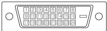
| No. | Function | No. | Function |
| 1 | TMDS data 2- | 16 | Hot-plug detection |
| 2 | TMDS data 2+ | 17 | TMDS data 0- |
| 3 | TMDS data 2/4 shield | 18 | TMDS data 0+ |
| 4 | N.C. | 19 | TMDS data 0/5 shield |
| 5 | N.C. | 20 | N.C. |
| 6 | DDC clock | 21 | N.C. |
| 7 | DDC data | 22 | TMDS clock shield |
| 8 | N.C. | 23 | TMDS clock+ |
| 9 | TMDS data 1- | 24 | TMDS clock- |
| 10 | TMDS data 1+ | ||
| 11 | TMDS data 1/3 shield | ||
| 12 | N.C. | ||
| 13 | N.C. | ||
| 14 | +5 V | ||
| 15 | GND | ||
PC analogue RGB input terminal pins (Mini D-sub 15 pin)
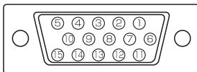
| No. | Function | No. | Function |
| 1 | Red video signal input | 9 | +5 V |
| 2 | Green video signal input | 10 | GND |
| 3 | Blue video signal input | 11 | N.C. |
| 4 | N.C. | 12 | DDC data |
| 5 | GND | 13 | Hsync signal input |
| 6 | GND for red video signal | 14 | Vsync signal input |
| 7 | GND for green video signal | 15 | DDC clock |
| 8 | GND for blue video signal | ||
RS-232C input terminal pins
(D-sub 9 pin)
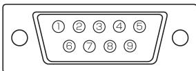
| No. | Function | No. | Function |
| 1 | N.C. | 6 | Data set ready |
| 2 | Transmitted data | 7 | Request to send |
| 3 | Received data | 8 | Clear to send |
| 4 | Data terminal ready | 9 | N.C. |
| 5 | GND |
RS-232C output terminal pins
(D-sub 9 pin)
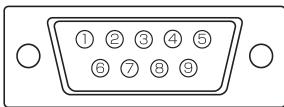
| No. | Function | No. | Function |
| 1 | Carrier detect | 6 | Data set ready |
| 2 | Received data | 7 | Request to send |
| 3 | Transmitted data | 8 | Clear to send |
| 4 | Data terminal ready | 9 | Ring indicator (open) |
| 5 | GND |
PC digital RGB output terminal pins
(DVD-D 24 pin)
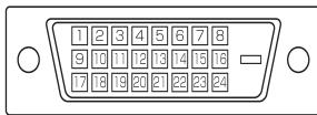
| No. | Function | No. | Function |
| 1 | TMDS data 2- | 16 | Hot-plug detection |
| 2 | TMDS data 2+ | 17 | TMDS data 0- |
| 3 | TMDS data 2/4 shield | 18 | TMDS data 0+ |
| 4 | N.C. | 19 | TMDS data 0/5 shield |
| 5 | N.C. | 20 | N.C. |
| 6 | DDC clock | 21 | N.C. |
| 7 | DDC data | 22 | TMDS clock shield |
| 8 | N.C. | 23 | TMDS clock+ |
| 9 | TMDS data 1- | 24 | TMDS clock- |
| 10 | TMDS data 1+ | ||
| 11 | TMDS data 1/3 shield | ||
| 12 | N.C. | ||
| 13 | N.C. | ||
| 14 | +5 V | ||
| 15 | GND | ||
Dimensional Drawings
Monitor unit only
Unit: mm
Note that the values shown are approximate values.
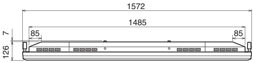
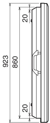
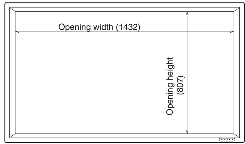
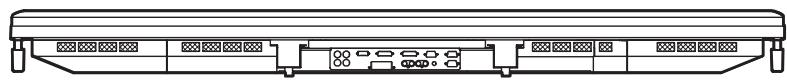
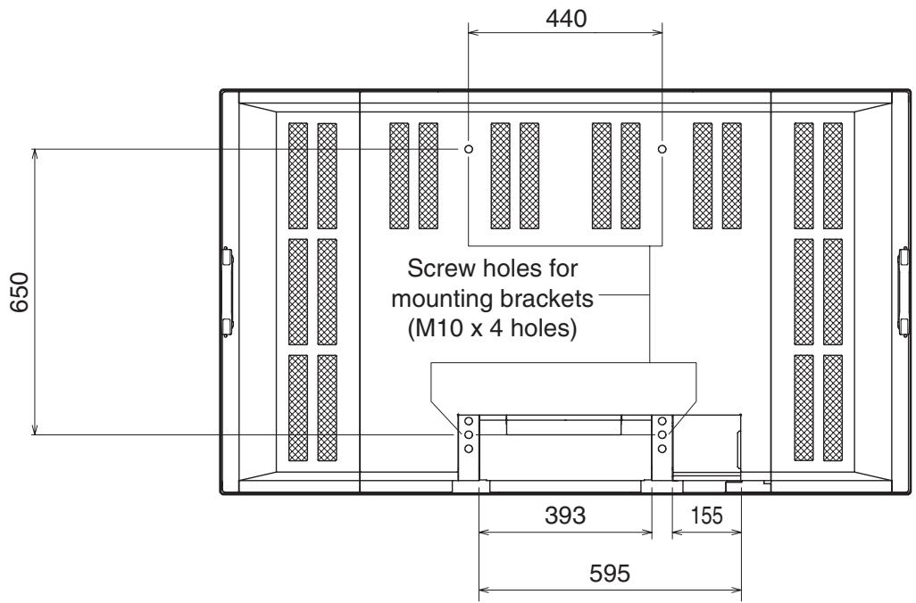
Menu Option Reference Chart
DIGITAL
| WHITE BALANCE | THRU | |
| COOL | ||
| • | ||
| STD | ||
| • | ||
| WARM | ||
| USER | R-CONTRAST 0 to 255 | |
| COPY TO USER | G-CONTRAST 0 to 255 | |
| B-CONTRAST 0 to 255 | ||
| MODE SELECT 1 | BEZEL | V: 0 to 100, H: 0 to 100 |
| ENLARGE | OFF, 2 x 2, 3 x 3, 4 x 4 | |
| ENLARGE-POS | 2 x 2: 0 to 3, 3 x 3: 0 to 8, 4 x 4: 0 to 15 | |
| MULTI ZOOM | IMAGE ZOOM | |
| H-POS | ||
| V-POS | ||
| MODE SELECT 2 | OFF TIMER | 0 to 23 |
| OSD H-POSITION | ||
| OSD V-POSITION | ||
| ID No. SET | 0 to 255 | |
| LANGUAGE | ENGLISH | |
| COLOR SYSTEM | DEUTSCH | |
| FRANÇAIS | ||
| ITALIANO | ||
| ESPÁÑOL | ||
| AUTO | ||
| PAL | ||
| PAL-60 | ||
| SECAM | ||
| NTSC3.58 | ||
| NTSC4.43 | ||
| MODE SELECT 3 | PIP MODES | OFF, PIP, PbyP, PbyP2 |
| PIP SIZE | SMALL, MEDIUM, LARGE | |
| PIP H-POS | 0 to 100 | |
| PIP V-POS | 0 to 100 | |
| PIP BLEND | 0 to 15 | |
| PIP SOURCE | COMPONENT, VIDEO | |
| SOUND CHANGE | PC, AV | |
| MAIN POS | LEFT, RIGHT | |
| PbyP2 POS | TOP, CENTER, BOTTOM | |
| AUTO OFF | MANUAL, AUTO |
Menu Option Reference Chart (Continued)
ANALOG
| ADJUSTMENT | MANUAL | CLOCK | 0 to 255 |
| AUTO | PHASE | 0 to 255 | |
| RESET | H-POS | 0 to 255 | |
| V-POS | 0 to 255 | ||
| GAIN CONTROL | MANUAL | BLACK LEVEL | 0 to 31 |
| AUTO | CONTRAST | 0 to 31 | |
| WHITE BALANCE | COOL | ||
| • | |||
| STD | |||
| • | |||
| WARM | |||
| USER | R-CONTRAST | 0 to 255 | |
| COPY TO USER | G-CONTRAST | 0 to 255 | |
| B-CONTRAST | 0 to 255 | ||
| MODE SELECT 1 | 480 LINES | 848, 640 | |
| 768 LINES | 1360, 1280, 1024 | ||
| BEZEL | V: 0 to 100, H: 0 to 100 | ||
| ENLARGE | OFF, 2 x 2, 3 x 3, 4 x 4 | ||
| ENLARGE-POS | 2 x 2: 0 to 3, 3 x 3: 0 to 8, 4 x 4: 0 to 15 | ||
| MULTI ZOOM | IMAGE ZOOM | ||
| H-POS | |||
| V-POS | |||
| MODE SELECT 2 | OFF TIMER | 0 to 23 | |
| OSD H-POSITION | |||
| OSD V-POSITION | |||
| ID No. SET | 0 to 255 | ||
| LANGUAGE | ENGLISH | ||
| COLOR SYSTEM | DEUTSCH | ||
| FRANÇAIS | |||
| ITALIANO | |||
| ESPÁÑOL | |||
| AUTO | |||
| PAL | |||
| PAL-60 | |||
| SECAM | |||
| NTSC3.58 | |||
| NTSC4.43 | |||
| MODE SELECT 3 | PIP MODES | OFF, PIP, PbyP, PbyP2 | |
| PIP SIZE | SMALL, MEDIUM, LARGE | ||
| PIP H-POS | 0 to 100 | ||
| PIP V-POS | 0 to 100 | ||
| PIP BLEND | 0 to 15 | ||
| PIP SOURCE | COMPONENT, VIDEO | ||
| SOUND CHANGE | PC, AV | ||
| MAIN POS | LEFT, RIGHT | ||
| PbyP2 POS | TOP, CENTER, BOTTOM | ||
| AUTO OFF | MANUAL, AUTO |
COMPONENT/VIDEO
| VIDEO ADJUSTMENT | CONTRAST | 0 to 31 |
| BLACK LEVEL | 0 to 31 | |
| TINT | 0 to 31 | |
| COLORS | 0 to 31 | |
| SHARPNESS | 0 to 31 | |
| WHITE BALANCE | COOL, •, STD, •, WARM | |
| MODE SELECT 2 | OFF TIMER | 0 to 23 |
| OSD H-POSITION | ||
| OSD V-POSITION | ||
| ID No. SET | 0 to 255 | |
| LANGUAGE | ENGLISH | |
| COLOR SYSTEM | DEUTSCH | |
| FRANÇAIS | ||
| ITALIANO | ||
| ESPÁÑOL | ||
| AUTO | ||
| PAL | ||
| PAL-60 | ||
| SECAM | ||
| NTSC3.58 | ||
| NTSC4.43 | ||
| MODE SELECT 3 | PIP MODES | OFF, PIP, PbyP, PbyP2 |
| PIP SIZE | SMALL, MEDIUM, LARGE | |
| PIP H-POS | 0 to 100 | |
| PIP V-POS | 0 to 100 | |
| PIP BLEND | 0 to 15 | |
| PIP SOURCE | DIGITAL, ANALOG | |
| SOUND CHANGE | PC, AV | |
| MAIN POS | LEFT, RIGHT | |
| PbyP2 POS | TOP, CENTER, BOTTOM | |
| AUTO OFF | MANUAL, AUTO |
PN-655E
LCD MONITOR
DEUTSCH
WICHTIGE INFORMATIONEN
ACHTUNG: HALTEN SIE DAS GERÄT VON REGEN UND JEGLICHER ART VON FEUCHTIGKEIT FERN, UM DIE GEFAHR VON BRAND ODER STROMSCHLAG ZU VERRINGERN.

VORSICHT
ELEKTKROSCHOCK-GEFAHR NICTHTÖFFNEN

VORSICHT: ABDECKUNG NICT ENTFERNEN: GEFAHR VON ELEKTROSCHOCK. KEINE WARTUNGSTEILE IM INNEREN. SERVICEARBEITEN NUR VON QUALIFIZIERTEM FACHPERSONAL DURINGFühREN LASSEN.
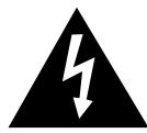
Conditions de communication
“ADJUSTMENT(ANALOG)”[调节(模拟式)]
Printed on 100% post-consumer recycled paper.