AV30MX-2 - Pregnant Stewart - Free user manual and instructions
Find the device manual for free AV30MX-2 Stewart in PDF.

User questions about AV30MX-2 Stewart
0 question about this device. Answer the ones you know or ask your own.
Ask a new question about this device
Download the instructions for your Pregnant in PDF format for free! Find your manual AV30MX-2 - Stewart and take your electronic device back in hand. On this page are published all the documents necessary for the use of your device. AV30MX-2 by Stewart.
USER MANUAL AV30MX-2 Stewart
AV30MX-2 User Manual

text_image
STEWARTAUDIO AV30MX-2
text_image
UL 2043 Plenum Rated L Speaker R Mute Pwr LEVEL Input 2 Input 1 On L Clip R Sig Input 2 R Input 1 L1 Important safety instructions
- Please read carefully prior to product installa on or opera on.
- Read these instructions.
- Keep these instructions.
- Heed all warnings.
- Follow all instructions.
- Do not use this apparatus near water.
- Clean only with dry cloth.
- Do not block any ventilation openings. Install in accordance with manufacturer's instructions.
- Do not install near any heat sources such as radiators, heat registers, stoves, or other apparatus (including amplifiers) that produce heat.
- The unit should only be connected to 120-240VAC, 50-60 Hz power supply. Use only the power adapter that is sold with the unit.
- Protect the power cord from being walked on or pinched particularly at plugs, convenience receptacles, and the point they exit from the apparatus.
- Only use attachments/accessories specified by the manufacturer.
- Unplug this apparatus during lightning storms or when unused for long periods of time.
- Refer all servicing to qualified service personnel. Servicing is required when the apparatus has been damaged in any way, such as power-supply cord or plug is damaged, liquid has been spilled or objects have fallen into the apparatus, the apparatus has been exposed to rain or moisture, does not operate properly, or has been dropped.
2 Approvals
This equipment has been tested and found to be compliant with the limits for Class A Digital device pursuant to part 15 of the FCC rules, and in compliance with the EN55022 and EN55024 EMC standards.
3 Warnings
3.1 Explanation of Warning Symbols
3.1.1 Lightning Bolt

The lightning bolt within arrowhead symbol, within an equilateral triangle, is intended to alert the user to the presence of un-insulated “dangerous voltage” within the product’s enclosure that may be of sufficient magnitude to consult a risk of electrical shock to person.

3.1.2 Exclamation Point
The exclama on point within an equilateral triangle is intended to alert the user to the presence of important operating and maintenance (servicing) instruction in the literature accompanying the appliance.
3.2 Warnings
WARNING: TO REDUCE THE RISK OF ELECTRICAL SHOCK, DO NOT EXPOSE THIS PRODUCT TO RAIN OR MOISTURE. DANGEROUS HIGH VOLTAGES ARE PRESENT INSIDE THE ENCLOSURE. DO NOT OPEN THE CABINET. REFER SERVICING TO QUALIFIED PERSONNEL ONLY.

text_image
CAUTION: TO REDUCE THE RISK OF ELECTRIC SHOCK, DO NOT REMOVE COVER (OR BACK). NO USER- SERVICEABLE PARTS INSIDE. REFER SERVICING TO QUALIFIED SERVICE PERSONNEL.3.3 User Responsibility
3.3.1 Radio Interference
This product has been tested and complies with the EMC direc ve, and with FCC part 15 Class A. If this product is not used in accordance with these opera ng instruc ons, it may cause interference with to other equipment, such as radio and television receivers.
3.3.2 Maintenance
Clean regularly with a so cloth to remove dust and debris. Also check that there is adequate ven la on for convec on cooling.
4 Table of Contents
1 Important safety instruc ons....1
2 Approvals....2
3 Warnings....2
3.1 Explana on of Warning Symbols....2
3.1.1 Lightning Bolt....2
3.1.2 Exclama on Point....2
3.2 Warnings....2
3.3 User Responsibility 2
3.3.1 Radio Interference....2
3.3.2 Maintenance....2
4 Table of Contents ....3
5 Welcome....4
5.1 Features....4
5.2 Unpacking and Visual Inspection 4
5.3 Installa on and Setup....4
5.3.1 Moun ng....4
5.3.2 Product Dimensions.... 5
5.3.3 Cooling Considera ons....5
5.3.5 Input Connec ons....6
5.3.6 Output Connec ons....6
6 Controls and Indicators 7
6.1 Sleep Mode....7
6.2 Level Controls 7
6.3 Remote Mute....7
7 Technical Speci ca ons....8
8 Troubleshoo ng....9
9 Warranty Informa on 9
9.1 Warranty Summary 9
9.2 Eligibility Requirements....9
9.3 Non-warranty Repairs.... 10
9.4 Shipment Instruc ons 10
9.5 Packaging Instruc ons....11
10 Accessories....11
5 Welcome
Your Stewart Audio AV Series ampli er is the result of years of experience in the design and manufacture of quality ampli ers. As such it provides a combina on of performance and opera onal bene ts that simply cannot be found in conven onal ampli ers.
5.1 Features
- Sub Compact 1/4 rack package
• Op mized to drive 4Ω and 8Ω loads.
• Music and re alarm mu ng - Clean full-range dynamic power
• Signal Detect trigger for sleep & wake up - Mul ple moun ng op ons
• External inline power supply
• Class D convec on cooled
- Two channel stereo amplifier with built-in mixing capabili es
This product is proudly manufactured in the United States.
5.2 Unpacking and Visual Inspection
Every Stewart Audio product is carefully tested and inspected before leaving the factory and should arrive in perfect condi on. If any damage is discovered, please no fy the shipping carrier immediately. Save the packing materials for the carrier's inspection and for any future shipping.
5.3 Installation and Setup
5.3.1 Mounting
There are a number of different moun ng op ons for the AV30MX/PMX-2 to meet a variety of installa on requirements.
5.3.1.1 Pole Mounting
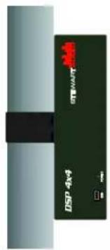
The AV30MX-2 has moun ng holes on both the top and side of the unit which can be used with the AV-Pole bracket available from Stewart Audio.
text_image
DSP 4x4 STWNTY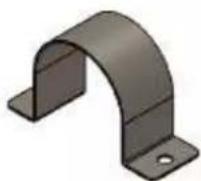
Part Number: AV-Pole

natural_image
Solid dark green rectangular panel with a black horizontal bar and four small circular holes, no text or symbols present.5.3.1.2 Universal Mounting
AV30MX-2 User Manual Rev D Page 4
Table of Contents
Top
The AV30MX-2 also has a universal bracket available which allows the unit to be mounted against a wall or under a table. Two screws are included in the kit which will a x the bracket to the top of the unit. Once this is done, two holes are available for moun ng the unit where desired.

CAUTION: Use only the screws provided in moun ng the brackets to the unit. Do not over ghten.
5.3.2 Product Dimensions

text_image
4.35" 110mm AV30MX-2 STEWART AUDIO 1.25" 32mm 3.2" 81mm 1.25" 32mmPart Number: AV-Bracket
5.3.3 Cooling Considerations
Because the AV30MX-2 is cooled by convec on with no fans, the ampli er must be given adequate space to allow for proper air ow. Do not stack the ampli ers on top of each other or mount it in a way that other equipment will block air ow around the case.

CAUTION: Inadequate air ow can cause the ampli er to overheat and poten ally become damaged. Be sure to provide plenty of air space to allow for convec on cooling.
5.3.5 Input Connections
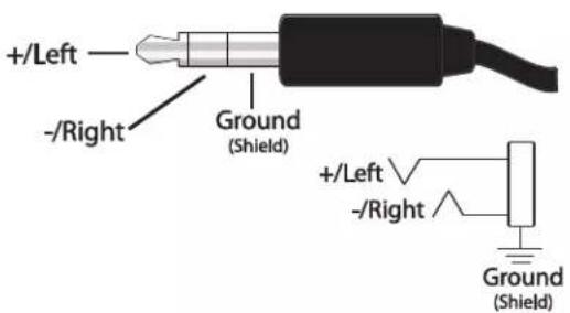
Your AV30MX-2 has two independent stereo inputs which are then mixed into the nal output. Input 1 will accept a stereo 3.5mm jack while input 2 will accept stereo RCA phono plugs. Both inputs should be stereo, unbalanced, and line-level. Note that the input sensi vity is 0.5V (-6dBV). Do not overdrive the ampli er! The AV30MX-2 does not include a pre-ampli er. Refer to the diagrams below for proper wiring for the 3.5mm and RCA inputs.
text_image
+/Left -/Right Ground (Shield) +/Left -/Right Ground (Shield)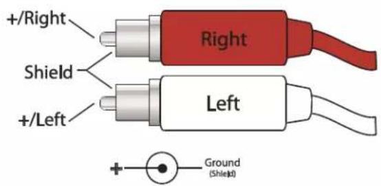
text_image
+/Right Shield +/Left Right Left Ground (Shleid)5.3.6 Output Connections
Stewart Audio recommends using high-quality, heavy-gauge speaker wire and connectors to send the output signal of your amplifier to the speakers. Use the following table as a guideline when selecting your wire gauge.
| Distance | Wire Gauge |
| Up to 25 (up to 8 m) | 16 AWG |
| 25-40 (8-12 m) | 14 AWG |
| 40-60 (12-18 m) | 12 AWG |
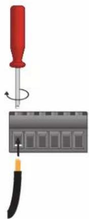
Speaker leads connect by means of terminal block connectors supplied with the unit. Strip speaker leads 1/4" (6.4mm) and insert into connector observing proper polarity. With a small, at-blade screwdriver, ghten the screw until the leads are held securely in place. Inspect for possible shorts or broken wires.
The AV30MX-2's two stereo inputs are mixed and then sent to the le and right speakers. The expected speaker setup is a 8Ω or 4Ω con gura on (not to exceed 30W per side). Refer to the following diagram as a reference for connec ng your speakers.
natural_image
Illustration of a screwdriver holding a screwdriver above a circuit board with a tool (no text or symbols visible)
flowchart
graph TD
    A["Central Block"] --> B["Left Channel"]
    A --> C["Right Channel"]
    B --> D["Terminal Node 1"]
    C --> E["Terminal Node 2"]
    D --> F["Terminal Node 3"]
    E --> G["Terminal Node 4"]
6 Controls and Indicators
text_image
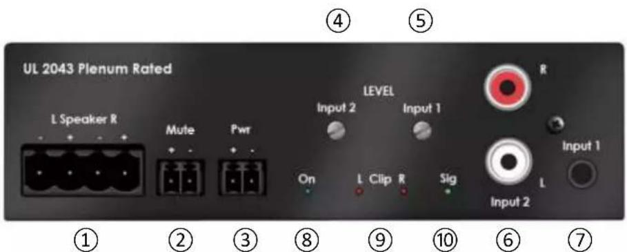
UL 2043 Plenum Rated L Speaker R Mute Pwr LEVEL Input 2 Input 1 On L Clip R Sig Input 2 ① ② ③ ⑧ ⑨ ⑩ ⑥ ⑦ R Input 1 L- Speaker output connector: 3.5mm Eurostyle connector (refer to Sec on 5.3.6).
- Remote mute connector: 3.5mm Eurostyle contact closure. Short terminals for mute; open to unmute. Note: Ampli ers with a serial number pre x SF conform to this mute conven on. Older models with the serial number pre x SC require +5 to +12VDC to mute.
- Power connector: 3.5mm Eurostyle connector. Use only power adapter supplied with unit. Be careful not to insert this connector into the Mute connector loca on!
- Input 2 level control: Fully clockwise is full power.
- Input 1 level control: Fully clockwise is full power.
- Input 2 connectors: RCA phono. 0.5V rms provides full output power.
- Input 1 connector: 3.5mm. 0.5V rms provides full output power.
- Power indicator: LED illuminates when power is applied.
- Clip indicator LEDs: If either LED is illuminated, reduce the input signal level of that channel.
- Signal present indicator: LED illuminates when a signal is present at any input.
6.1 Sleep Mode
When no input signal is detected for a period of approximately 5 minutes, the amplifier will enter sleep mode to reduce power. The AV30MX-2's Signal Sense Technology will power up the unit when a signal is subsequently detected.
6.2 Level Controls
There are 2 level controls to adjust the level of the input signals. The level 1 control adjusts both the le and right signal levels on input 1. Similarly, input level control 2 adjusts the le and right level of input 2 signals. Be certain to monitor the clip indicators when adjusting the input levels.
6.3 Remote Mute
The AV30MX-2 can be remotely muted (such as m u ng during a re alarm by grounding the mute terminal. Leaving this terminal open will unmute the outputs. Note: Amplifiers with a serial number pre x SF conform to this mute conven on. Older models with the serial number pre x SC require +5 to +12VDC to mute.
7 Technical Specifications
| Maximum output (30Hz – 20kHz) | |
| Stereo | 30W @ 4Ω or 8Ω per channel |
| Frequency response (+0, -3dB) | 30Hz – 20kHz |
| Bandwidth (±3dB) | 30Hz – 30kHz |
| THD + Noise | <0.1% @ 1W |
| Signal to noise ra o | >100dB |
| External mute | +5 to +12VDC (3.5mm connector) |
| Slew rate | 30V/msec |
| Input sensi vity | 0.5V (-6dBV) |
| Standard voltage gain | 28 (26.5dB) |
| Input impedance (unbalanced) | 10kΩ |
| Current draw | |
| Sleep | 5 mA |
| Idle | 10 mA |
| 1/8 power | 150 mA |
| Class | D |
| Input connectors | 3.5mm stereo; Dual RCA |
| Output connectors | 5mm Euro block |
| Power supply | External in-line (Universal AC to +48VDC) |
| Cooling | Convec on; no fans |
| Controls | 2 independent input level controls; mute |
| LED indicators | Power; signal present; clip (2) |
| Construc on | Aluminum enclosure |
| Dimensions | |
| Height | 1.25 inches (32mm) |
| Width | 4.35 inches (111 mm) |
| Depth | 3.2 inches (81 mm) |
| Weight | 0.37 lbs. (0.16 kg) |
| Warranty | 3 years |
Stewart Audio reserves the right to change features and speci ca ons without no ce.
8 Troubleshooting
No power LED indicator
- Check that the amplifier is plugged into a live outlet. A er you have ensured that it is not an AC power issue, disconnect any speakers. If the amplifier turns on a er a few seconds delay, then the problem is in the output connec on. Check wiring and speakers for short circuits.
No output on one or both channels; Power indicator is lit.
- Check that level controls are not turned down. Check that input and output connec ons are secure. Ensure signal present LED is ashing to denote a signal. If there is no signal detected check signal source and that level controls are set high enough.
Ampli er overheats and/or shuts o .
- Review Sec on 5.3.3 on proper cooling considera ons. Check the signal lights on the rear of the amplifier to see if the signal is overdriving (the signal light ashes red frequently). Overdriving the amplifier for extended periods of me can cause a thermal shutdown.
Output sound is distorted or cracking.
- Check all cables for damage or loose connec ons and reduce the input signal level at the mixer or preamp level. Replace the cables and loudspeakers temporarily to see if this resolves the problem.
9 Warranty Information
9.1 Warranty Summary
All Stewart Audio products and accessories, unless excluded in this summary, are covered by a 3-year limited warranty on parts and labor from the data of purchase. In order to be eligible for warranty repairs, the products and accessories must have been purchased through an authorized Stewart Audio dealer and submitted by the original purchaser. This warranty is only valid in the country in which the product was purchased.
9.2 Eligibility Requirements
Stewart Audio warrants against all malfunc ons which come as a result of component or manufacturer defect. The product is also covered from all failures which arise during the warranty period (3 years from date of purchase) that are not a result of misuse. The following ac ons will void your warranty:
- The power cord or AC plug has been damaged through misuse.
- The product has been exposed to moisture or extreme temperatures.
- The product has been dropped, items have been dropped on the product, or the enclosure has been damaged.
• The product has been opened by the operator.
- The product was improperly packaged when sending to the factory for repair, resulting in damage.
• Any of the precau ons or instruc ons found in this manual were not followed.
Damages resul ng to the product which are not covered under this warranty can be factory-repaired at cost to the customer. Use the contact informa on below to ini ate the repair process.
9.3 Non-warranty Repairs
An es mate for all non-warranty repairs will be provided to the customer once the unit has been shipped to the factory. The customer is responsible to approve this es mate within 7 days. If the repairs are not approved within 14 days, Stewart Audio reserves the right to consider the unit scrap and may discard it. Payment for non-warranty repairs must be submitted to Stewart Audio before the product will be returned to the customer.
All returns to the factory for service must be accompanied by a Return Authoriza on (RA) number. One can be obtained by contacting Stewart Audio at (209) 588-8111 or via e-mail at support@stewartaudio.com.
NOTE: Any defec ve products received without an RA number will be returned to sender at their expense.
If Stewart Audio is unable to contact the sender in 14 days, the merchandise will be considered scrap and may be disposed of.
9.4 Shipment Instructions
- If Stewart Audio requests that you ship the defec ve product back to their service center, please refer to the guide below. To ensure prompt warranty service, be sure to follow all instruct ons.
• Return Authoriza on (RA) is required for product being sent to the factory for service.
• See packing instruc ons in Sec on 9.5.
- Ship the defect ve product using a method which provides for order tracking or order con rma on. The service center is located at the following address:
Stewart Audio
14335 Cuesta Court Suite C
Sonora, CA 95370
• Use a bold black marker and write the RA number on three sides of the box.
Record the RMA number for future reference. The RA number can be used to check the repair status.
9.5 Packaging Instructions
Should Stewart Audio request that you ship your product to their service center, these instruct ons must be followed in order to ensure safe delivery. If they are not followed, Stewart Audio assumes no responsibility for damaged goods and/or accessories that are sent with your unit.
- Please write the RA number on three sides of the box. Include the Stewart Audio RA number inside the box and a brief descrip on of the problem.
- You will be advised during the RA process what accessories should be included with the product (power supplies, connectors, cords, etc.). This is dependent on the failure assessment.
- When shipping your product, it is important that it has adequate protec on. We recommend you use the original packing material when returning the product for repair. If you do not have the original box, see number 4.
- If you provide your own shipping pack, use materials adequate to prevent damage during transit. Make certain that the product is NOT free to move within the package, as this is the most common cause of damage.
- Securely seal the package with an adequate carton sealing tape.
- Do not use light boxes or "peanuts".
NOTE: Damage caused by poor packaging will not be covered under warranty.
10 Accessories
The following amplifier accessories are available from Stewart Audio. All part numbers shown are Stewart Audio part numbers.
| Moun ng Brackets | |
| AV-POLE | Pole-mount bracket for AV Series ampli ers |
| AV-BRACKET | Universal moun ng bracket for AV Series ampli ers |