
CVA50MX-1 - Cellphone Stewart - Free user manual and instructions
Find the device manual for free CVA50MX-1 Stewart in PDF.


| Product Type | Cellphone / Mobile Phone |
| Brand | Stewart |
| Model | CVA50MX-1 |
| Dimensions (approx.) | 110 x 50 x 15 mm |
| Weight (approx.) | 90 g |
| Display | 1.8-inch TFT color screen |
| Battery | Li-Ion 800 mAh, removable |
| Talk Time | Up to 4 hours |
| Standby Time | Up to 200 hours |
| Charging Interface | Micro USB |
| SIM Card | Dual SIM (GSM) |
| Memory Card | MicroSD up to 32 GB |
| Camera | VGA (0.3 MP) |
| Connectivity | Bluetooth 2.1, FM Radio |
| Audio | Speakerphone, 3.5mm headphone jack |
| Main Functions | Call, SMS, Alarm, Calculator, Calendar, Torch |
| Languages | Multilingual (English, French, etc.) |
| Power Supply | Via AC adapter (included) or USB |
| Cleaning and Maintenance | Wipe with a soft dry cloth. Do not use harsh chemicals. |
| Safety | Avoid exposure to water and extreme temperatures. Use only approved accessories. |
| Spare Parts and Repairability | Contact authorized service center for battery and screen replacement. |
| Package Contents | Phone, Battery, Charger, User Manual |
| Color Options | Black (typical) |
Frequently Asked Questions - CVA50MX-1 Stewart
User questions about CVA50MX-1 Stewart
0 question about this device. Answer the ones you know or ask your own.
Ask a new question about this device
Download the instructions for your Cellphone in PDF format for free! Find your manual CVA50MX-1 - Stewart and take your electronic device back in hand. On this page are published all the documents necessary for the use of your device. CVA50MX-1 by Stewart.
USER MANUAL CVA50MX-1 Stewart
The Difference is Hear


CVA50MX-1 CVA50PMX-1
Owner's Manual
August 2013
www.stewartaudio.com
Important Safety Instructions
Before using your Stewart Audio Inc. Power Amplifier, please read this Owner's Manual carefully to ensure optimum trouble-free performance.
WARNING: TO REDUCE THE RISK OF ELECTRICAL SHOCK, DO NOT EXPOSE THIS AMPLIFIER TO RAIN OR MOISTURE. DANGEROUS HIGH VOLTAGES ARE PRESENT INSIDE THE ENCLOSURE. DO NOT OPEN THE CABINET. REFER SERVICING TO QUALIFIED PERSONNEL ONLY.


CAUTION: TO REDUCE THE RISK OF ELECTRIC SHOCK, DO NOT REMOVE COVER (OR BACK). NO USER-SERVICEABLE PARTS INSIDE. REFER SERVICING TO QUALIFIED SERVICE PERSONNEL.

The lighting bolt within arrowhead symbol, within an equilateral triangle, is intended to alert the user to the presence of un-insulated "dangerous voltage" within the product's enclosure that may be of sufficient magnitude to constitute a risk of electrical shock to person.

The exclamation point within an equilateral triangle, is intended to alert the user to the presence of important operating and maintenance (servicing) instruction in the literature accompanying the appliance.
Important Safety Instruction – Please Read Prior to Product Installation.
- Installation should be performed by a trained and licensed professional to insure safe and lasting operation.
-
All of the safety and operating instructions should be read before the amplifier is installed or operated. Retain these instructions for future reference. All instructions should be followed; all warnings on the amplifier and in the operating instructions should be adhered to.
-
The amplifier should be situated so that its location and position does not interfere with its proper ventilation. For example, the amplifier must not be placed on a rug, bed, sofa or similar surface that impedes airflow across the chassis. Airflow through the ventilation openings should be unobstructed.
- This amplifier should not be used near water, for example, near a bathtub, in a wet basement, near a swimming pool, etc. This amplifier is intended to be operated in a controlled indoor environment.
- Do not place the amplifier near heat sources such as radiators, heat registers, stoves, or other appliances that produce heat.
- The amplifier should only be connected to 120 VAC, 60 Hz power supply. Do not defeat the ground or polarization of the power plug.
- Route power cord and other cables so that they are not likely to be walked on, tripped over or stressed. Pay particular attention to condition of cords and cables at plugs and at the point where they exit the amplifier. To prevent risk of fire or injury, damaged cords and cables should be replaced immediately.
- Clean the amplifier with a clean, damp cloth. Do not use solvents or abrasive cleaners. Never pour any liquid on the amplifier.
- When left unused for a long period of time, the power cord should be unplugged form the outlet.
-
Damaged Amplifiers requiring service should be repaired by a qualified service technician when:
a. The power cord or AC plug has been damaged.
b. Objects have fallen, or liquid has spilled into the unit.
c. The amplifier has been exposed to rain or other moisture.
d. The amplifier does not appear to operate normally or exhibits a marked change in performance.
e. The amplifier has been dropped or the enclosure damaged. -
The user should not attempt to service the amplifier beyond that described in the operating instructions. All other servicing should be referred to qualified service personnel.
Table of Contents
Important Safety Instructions....2
Table of Contents 4
1 Welcome 5
1.1 Features 5
1.2 Using this Manual 5
2 Setup 6
2.1 Setup Precautions 6
2.2 Amplifier Installation 6
2.3 Proper Cooling Considerations 7
2.4 Input Connections 8
2.5 Output Connections 10
3 Operation 14
3.1 Operation Precautions 14
3.2 Controls, Indicators, and Connectors 15
3.3 Special Features 18
4 Troubleshooting....19
5 Technical Specifications 21
6 Warranty Information 22
6.1 Warranty Summary 22
6.2 Return Procedure 22
7 Accessories 25
8 Notes 26

This amplifier proudly designed and manufactured in the USA.
1 Welcome
STEWART

The Difference is Hear
Congratulations on the purchase of your new Stewart Audio CVA50MX-1 / CVA50PMX-1 power amplifier. This amplifier has been designed and built to provide you with years of high-quality audio performance and trouble-free operation. If after reading this manual you should have any questions concerning amplifier installation and operation, please contact your Authorized Stewart Dealer, or you may contact us directly using the contact information provided on the back of this manual.
1.1 Features
Your Stewart Audio CVA50MX-1 / CVA50PMX-1 amplifier is the result of years of experience in the design and manufacture of quality amplifiers. As such it provides a combination of performance and operational benefits that simply cannot be found in conventional amplifiers.
- Sub Compact 1/3 rack package
• 4 input mono mixer amplifier
• Music and fire alarm muting - Clean full-range dynamic power
• Signal Sense Technology for Energy Star Compliance - Multiple mounting options
• External inline power supply
• Made in the USA
1.2 Using this Manual
In order to obtain maximum performance from your CVA50MX-1 / CVA50PMX-1 Amplifier, please take time to read this brief owner's manual and carefully follow the guidelines for connection and operation.
This manual provides you with the information necessary to safely install and operate your new CVA50MX-1 / CVA50PMX-1 amplifier in the most common scenarios. If you find yourself requiring additional assistance, please feel free to contact your Authorized Dealer, or you may contact us directly using the information provided on the back of this manual.
2 Setup
2.1 Setup Precautions

CAUTION: Before installing your amplifier, make sure that you have read the Important Safety Precautions at the beginning of this manual.
2.2 Amplifier Installation
The CVA50MX-1 / CVA50PMX-1 incorporates a number of different mounting options in order to fit your installation needs.
2.2.1 Pole-Mounting
The CVA50MX-1 / CVA50PMX-1 has mount holes on both the top as well as the side of the unit which can be used with the AV-Pole bracket available from Stewart Audio.


Part Number: AV-Pole
2.2.2 Product Dimensions
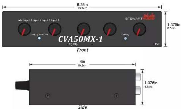
2.3 Proper Cooling Considerations
Because the CVA50MX-1 / CVA50PMX-1 regulates its temperature using convection cooling and no fans, the amplifier must be given adequate space to allow for proper airflow. Do not stack the amplifiers on top of each other or mount it in a way that other equipment will block airflow through the case.

CAUTION: Inadequate airflow to the amplifier can cause the amplifier to overheat and potentially become damaged in the process. Be sure to provide plenty of air space to allow for convection cooling.
2.4 Input Connections
The CVA50MX-1 / CVA50PMX-1 has 4 inputs which are mixed into the final mono output. The first input channel is for a balanced microphone and the rest are stereo, unbalanced inputs. All stereo inputs are summed to mono prior to being mixed.
CVA50MX-1-xxV (70V or 100V):
When a signal is applied to input 1, inputs 2-4 will be ducked as per the setting of the "duck" control. The level for each input channel is set with the corresponding control. The master volume control and remote volume set the level of all inputs including input 1.
CVA50PMX-1-xxV (70V or 100V):
When a signal is applied to input 1, inputs 2-4 will be ducked as per the setting of the "duck" control. The level for each input channel is set with the corresponding control. The master volume control and remote volume set the level of inputs 2-4. The input 1 level control is independent and not affected by the master or remote controls.
2.4.1 Input 1—Microphone
The first input channel is for a balanced microphone and includes an adjustable pre-gain as well as phantom power for the use of condenser microphones. A pin-out diagram compatible with the CVA50MX-1 / CVA50PMX-1 is included below. For pre-gain adjustment and phantom power, refer to Section 3.2.2.

2.4.2 Input 2—RCA
The second input channel is a stereo RCA jack which is then summed to mono before the final output. Refer to the diagram below for wiring directions.
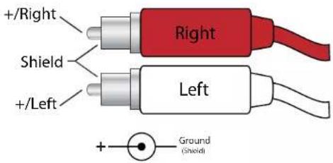
2.4.3 Input 3—Stereo Euroblock
The third input channel is a euro block connector which can be wired to any unbalanced input. Should you be wiring up a stereo source, use both the left and right pins of the connector. A mono source will only require the use of the ground and left pins.
2.4.4 Input 4—Stereo 3.5mm
The second input channel is a stereo RCA jack which is then summed to mono before the final output. Refer to the diagram below for wiring directions.

9
2.5 Output Connections
Stewart Audio recommends using high-quality speaker wire and connectors to send the output signal of your amplifier to the speakers. The gauge of the wire will be dependent on both the output type used (4/8 ohm, 25V/70V, or 25V/100V) as well as the length of the run to the speakers. Use the following tables as a guideline when selecting your wire gauge.
4/8 Ohm Installation
Distance Wire Gauge
Up to 25 ft. 16 AWG
26-40 ft. 14 AWG
41-60 ft. 12 AWG
25V/70V/100V Installation
Distance Wire Gauge
Up to 500 ft. 22 AWG
500-1000 ft. 20 AWG
Over 1000 ft. 18 AWG
Speaker leads connect by means of terminal block connectors supplied with the unit. Strip speaker leads 1/4" and insert into connector observing proper polarity. With a small, flat-blade screwdriver, tighten the screw until the leads are held securely in place. Inspect for possible shorts or broken wires.
10
2.5.1 25W x 2 @ 4/8 ohms
The CVA50MX-1 / CVA50PMX-1 allows for two output channels into 4 or 8ohms at 25 watts a channel. Both channels will have identical mono output, they will not correlate to left or right channels. Refer to the diagram below when connecting speakers in this setup.

*25V/70V or 25V/100V based on model selection.
2.5.2 50W x 1 @ 8 ohms
The CVA50MX-1 / CVA50PMX-1 can bridge it's 4/8 ohm output into one 50W channel. This can be done by connecting standard speakers to the +25V output, similar to using a 25V constant voltage system without the transformers. Refer to the diagram below when connecting speakers in this setup.
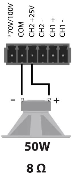
*25V/70V or 25V/100V based on model selection.
2.5.3 Constant Voltage (25V/70V/100V)
The CVA50MX-1 / CVA50PMX-1 can additionally be setup as a constant voltage amplifier for a distributed audio solution. It is capable of supplying both 25V and 70V output or 25V and 100V output. Refer to the following diagrams below when connecting speakers.

*25V/70V or 25V/100V based on model selection.
2.5.3 Line Out
The CVA50MX-1 / CVA50PMX-1 includes a post-mix unbalanced Line Out on the rear of the amplifier using a 2-pin Euroblock connector. This can be used for Assisted Listening applications, recording, or daisy-chaining multiple amplifiers.
3 Operation
3.1 Operating Precautions
- Before use, your amplifier must be configured for proper operation, including input and output wiring hookup. Improper wiring can result in damage to equipment or potentially harm to the operator. Consult section 2 for setup instructions.
- Tampering with the circuitry, or making unauthorized changes is not only dangerous but may also violate local regulations.
- Use care when making connections between the amplifier and the input or output equipment. Using equipment that is not capable of handling the output wattage may lead to permanent damage.

NOTE: Stewart Audio will not be held responsible for damage to your CVA50MX-1 / CVA50PMX-1 or connected equipment if the instructions in this manual are not followed.
3.2 Indicators and Controls
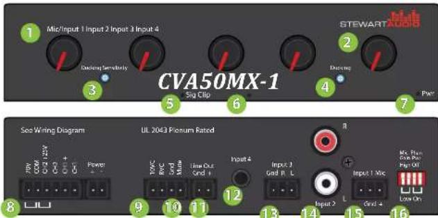
1 Input Volume Controls
9 Remote Volume Control
2 Master Volume Control
10 Remote Muting
3 Ducking Sensitivity Knob
11 Line Out
4 Ducking Knob
12 Input 4 - Stereo 3.5mm
5 Signal Present Indicator LED
13 Input 3 - Stereo Euroblock
6 Clip Indicator LED
14 Input 2 - Stereo RCA
7 Power Indicator LED
15 Input 1 - Balanced Microphone
8 Output Euroblock
16 Microphone DIP Switches
*CVA50MX-1:
When a signal is applied to input 1, inputs 2-4 will be ducked as per the setting of the "duck" control. The level for each input channel is set with the corresponding control. The master volume control and remote volume set the level of all inputs including input 1.
*CVA50PMX-1:
When a signal is applied to input 1, inputs 2-4 will be ducked as per the setting of the "duck" control. The level for each input channel is set with the corresponding control. The master volume control and remote volume set the level of inputs 2-4. The input 1 level control is independent and not affected by the master or remote controls.
3.2.1 Indicators
The CVA50MX-1 / CVA50PMX-1 has 3 front panel LED indicators. The power indicator (Pwr) will illuminate bright blue when power is supplied to the amplifier. If power is supplied but the LED is off, this means that the amplifier is in sleep mode. Once signal is detected by the Signal Sense circuit, the LED will turn back on.
The Signal Present indicator (Sig) will illuminate green when signal is detected on any of the 4 input channels.
The last indicator is the Clip/Distortion LED. This indicator means that one of the input signals is too "hot" and will sound distorted when amplified. To fix this, the gain should be reduced at the preamp or mixer level.
3.2.2 Controls
All CVA50MX-1 / CVA50PMX-1 controls are located on the rear of the unit. There is no power switch so the CVA50MX-1 / CVA50PMX-1 will turn on whenever power is supplied to it. The CVA50MX-1 / CVA50PMX-1's Signal Sense Technology (SST™) will power up the amplifier from sleep when a signal is detected. After 5 minutes without an input signal the amplifier will go into sleep mode.
The front panel contains a volume control for each input channel as well as a master volume. It also contains 2 recessed controls for the microphone ducking. For more information on this, refer to section 3.3.2.

Note: For the highest sound quality, leave the master volume knob as low as possible and increase the channel volume before increasing the master volume.
The rear panel of the CVA50MX-1 / CVA50PMX-1 includes a set of 4 DIP switches which control both the pre-gain of the microphone as well as the +48VDC phantom power.
The “Mic Gain” setting will adjust for the sensitivity of microphones by different manufacturers beyond what the volume control offers. If the microphone is generally too loud, select the “High” setting by pushing both switches up. If the microphone is generally too quiet, select the “Low” setting by pushing both switches down.
If you are using a condenser microphone requiring +48VDC phantom power to operate, slide both switches down. Otherwise, leave the switches in the "up" position.
The diagram below is an example of a condenser microphone (requiring phantom power) and is loud enough without additional pre-gain supplied by the amplifier.
Mic Phan
Gain Pwr
High Off


Low On
3.3 Special Features
3.3.1 Signal Sense Technology™
Stewart Audio's Signal Sense Technology™ puts the amplifier into an Energy Star compliant sleep mode after five minutes of no signal being detected on any input channels. The blue Power Indicator LED will go off and the amplifier will wait for signal to be present again. Once signal is present, the amplifier will return to normal operation.
3.3.2 Microphone Ducking
The CVA50MX-1 / CVA50PMX-1 includes a ducking feature which allows the microphone channel (Input 1) to talk over the other 3 channels. When a loud enough sound is detected on Input 1 it will lower channels 2-4 by a set amount. Both the sound threshold to activate the ducking (Ducking Sensitivity) and the amount the other channels are lowered (Ducking) are configurable via knobs on the front panel.
To properly adjust the ducking you should first play a typical source audio (song, movie, etc.) through any of the channels 2-4. Once this is playing, connect a microphone to channel 1 and begin to speak at a typical level. You should hear the source audio lower when you speak into the microphone. Using a small screwdriver, adjust the "Ducking Sensitivity" knob to set the sound threshold which activates the ducking. Next, adjust the "Ducking" knob to set the amount the other channels should be lowered. Turning the knob all the way counter-clockwise will mute channels 2-4 when ducking is activated.
4 Troubleshooting
Problem: Power indicator does not turn on.
Procedure: Check that the amplifier is plugged into a live outlet. After you have ensured that it is not a power issue, disconnect any speakers. If the amplifier turns on after a few seconds delay, then the problem is in the output connection. Check wiring and speakers for short circuits.
Problem: No output on one or both channels; Power indicator is lit.
Procedure: Check that level controls are not turned down. Check that input and output connections are secure. Refer to section 2.5 to ensure that you have properly connected your speakers. Ensure signal present LED is flashing to denote a signal. If there is no signal detected check signal source and that level controls are set high enough.
Problem: Microphone level is too low even after adjusting level knob
Procedure: Refer to section 3.2.2 to adjust the gain switch on the rear of the amplifier.
Problem: Channels 2-4 cut out while speaking into the microphone
Procedure: This is part of an intended feature calling ducking. Refer to section 3.3.2 to adjust this to a more acceptable level.
Problem: Amplifier overheats and/or shuts off.
Procedure: Review section 2.3 on proper cooling procedures. Check the signal lights on the front of the amplifier to see if the signal is overdriving (the Clip light flashes red frequently). Overdriving the amplifier for extended periods of time can cause a thermal shutdown.
4 Troubleshooting (Cont.)
Problem: Output sound is distorted or cracking.
Procedure: Check all cables for damage or loose connections and reduce the gain on the input signal at the mixer or preamp level. Replace the cables and loudspeakers temporarily to see if this resolves the problem. If problem still exists, contact your Authorized Dealer for service.
5 Technical Specifications
| Maximum Output | ||
| 25V/70V/100V | 50W | x 1 |
| 4/8 Ohm 25W x 2 or 50W x 1 | ||
| Frequency Response (Full Power) | 100Hz-20kHz | |
| Bandwidth +/- 3.0dB | 80Hz-30kHz | |
| THD+N <0.1% at 1W | ||
| Signal to noise ratio >90dB | ||
| Remote Volume Control | 0-10VDC | |
| Remote Muting | Contact Closure | |
| Microphone Ducking | 0 to -90dB (Adjustable) | |
| Phantom Power | +48VDC (Switchable) | |
| Input Sensitivity of Mic Input | 0dB (1V) or -30dB (30mV) | |
| Input Sensitivity of Inputs 2-4 | 0dB (1V) | |
| Standard Voltage Gain | 40x (32dB) | |
| Input Impedance | 10kOhms | |
| Standby, Idle, 1/8 Power Draw | .005/.01/.15 Amps | |
| Class | D | |
| Input Connectors | Mic (3-pin Euroblock), RCA, 3.5mm, 3-pin Euroblock | |
| Output Connectors | Euroblock | |
| Power Supply | External in-line 48VDC | |
| Cooling | Convection-cooling (No fans) | |
| Controls | 4 Level knobs, 1 Master, Ducking | |
| LED Indicators | 1.25in (3.2cm) | |
| Construction | 4.35in (11.1cm) | |
| Dimensions (H, W, D) | 3.2in (8.1cm) | |
| Weight | 0.37bs (0.16kg) | |
6 Warranty Information
6.1 Warranty Summary
All Stewart Audio amplifiers and accessories, unless excluded in this summary, are covered by a 3-year limited warranty on parts and labor from the data of purchase. In order to be eligible for warranty repairs, the amplifiers and accessories must have been purchased through an authorized Stewart Audio dealer and submitted by the original purchaser. This warranty is only valid in the country in which the amplifier was purchased.
6.1.1 Eligibility Requirements.
Stewart Audio warrants against all malfunctions which come as a result of component or manufacturer defect. The amplifier is also covered from all failures which arise during the warranty period (3 years from date of purchase) that are not a result of misuse. The following actions will void your warranty:
- The power cord or AC plug has been damaged through misuse.
- The amplifier has been exposed to moisture or extreme temperatures.
- The amplifier has been dropped, items have been dropped on the amplifier, or the enclosure has been damaged.
- The amplifier has been opened by the operator.
- The amplifier was improperly packaged when sending to the factory for repair, resulting in damage.
- Any of the precautions or instructions found in this manual were not followed.
Damages resulting to the amplifier which are not covered under this warranty can be factory-repaired at cost to the customer. Use the contact information below to initiate the repair process.
6.2 Return Procedure
This section includes the return procedures which must be followed in order to prevent processing delay or cost to the customer. Please read the entire section before contacting Stewart Audio for returns.
6.2.1 Return Authorization Number
All returns to the factory for service must be accompanied by a Return Authorization (RA) number. One can be obtained by contacting Stewart Audio at (209) 588-8111 or via e-mail at support@stewartaudio.com.
NOTE: Any defective products received without an RA number will be returned to sender at their expense.
If Stewart Audio is unable to contact the sender in 14 days, the merchandise will be considered scrap and may be disposed of.
6.2.2 Shipment Instructions
If Stewart Audio requests that you ship the defective product back to their service center, please refer to the guide below. To ensure prompt warranty service, be sure to follow all instructions.
- Return Authorization (RA) is required for product being sent to the factory for service.
- See packing instructions in section 6.2.3.
- Ship the defective product using a method which provides for order tracking or order confirmation. The service center is located at the following address:
Stewart Audio 14397 Cuesta Court Suite D1 Sonora, CA 95370
- Use a bold black marker and write the RA number on three sides of the box.
- Record the RMA number for future reference. The RA number can be used to check the repair status.
6.2.3 Packaging Instructions
Should Stewart Audio request that you ship your product to their service center, these instructions must be followed in order to ensure safe delivery. If they are not followed, Stewart Audio assumes no responsibility for damaged goods and/or accessories that are sent with your unit.
6.2.3 Packaging Instructions (cont.)
- Please write the RA number on three sides of the box. Include the Stewart Audio RA number inside the box and a brief description of the problem.
- Do not ship any accessories (manuals, cords, hardware, etc.) with your unit. These items are not needed to service your product. Stewart Audio will not be held responsible for these items if they are returned with the amplifiers.
- When shipping your amplifier, it is important that it has adequate protection. We recommend you use the original packing material when returning the product for repair. If you do not have the original box, see number 4.
- If you provide your own shipping pack, the minimum recommended requirements for materials are as follows:
a. 275 P.S.I. burst test, Double-Wall carton that allows for 2-inch solid Styrofoam on all six sides of unit or 3 inches of plastic bubble wrap on all six sides of unit.
b. Securely seal the package with an adequate carton sealing tape.
c. Do not use light boxes or "peanuts".
NOTE: Damage caused by poor packaging will not be covered under warranty.
6.2.4 Estimate Approval
An estimate for all non-warranty repairs will be provided to the customer once the unit has been shipped to the factory. The customer is responsible to approve this estimate within 7 days. If the repairs are not approved within 14 days, Stewart Audio reserves the right to consider the unit scrap and may discard it.
6.2.5 Payment of Non-Warranty Repairs
Payment for non-warranty repairs must be submitted to Stewart Audio before the product will be returned to the customer.
7 Accessories
The following accessories are available from Stewart Audio for your amplifier.
All part numbers shown are Stewart Audio Part Numbers.
Mounting Brackets
AV-POLE Pole-mount bracket for compact amplifiers
AV-BRACKET Universal mounting bracket for compact amplifiers
Connection Adapters
ADPT-RCA Mono Female RCA to male Euroblock.
ADPT-SUMRCA Stereo Female RCA to male Euroblock.
ADPT-SUM35 Stereo Female 3.5mm to male Euroblock
Wall Plates
WP-RVC-B Wallplate with 10k potentiometer and knob for remote volume control (Black)
WP-RVC-A Wallplate with 10k potentiometer and knob for remote volume control (Aluminum)
To purchase these accessories or to see the full Stewart Audio product lineup, visit us at:
www.stewartaudio.com
8 Notes
For Your Record
In the spaces provided below, record the model and serial number located at the rear of your amplifier.
Model No. ____
Serial No. ____
Purchase Date ____
Retain this information for future reference.
8 Notes (Cont.)
STEWART

The Difference is Hear
14397 Cuesta Court
Suite D1
Sonora, Ca. 95370
Phone: 209-588-8111
Fax: 209-588-8113
www.stewartaudio.com


- CVA50MX-1 CVA50PMX-1
- Important Safety Instructions
- Important Safety Instruction – Please Read Prior to Product Installation.
- Table of Contents
- Welcome
- Features
- Using this Manual
- Setup
- Setup Precautions
- Amplifier Installation
- Pole-Mounting
- Product Dimensions
- Proper Cooling Considerations
- Input Connections
- CVA50MX-1-xxV (70V or 100V):
- CVA50PMX-1-xxV (70V or 100V):
- Input 1—Microphone
- Input 2—RCA
- Input 3—Stereo Euroblock
- Input 4—Stereo 3.5mm
- Output Connections
- 4/8 Ohm Installation
- 25V/70V/100V Installation
- 25W x 2 @ 4/8 ohms
- 50W x 1 @ 8 ohms
- Constant Voltage (25V/70V/100V)
- Line Out
- Operation
- Operating Precautions
- Indicators and Controls
- Indicators
- Controls
- Special Features
- Signal Sense Technology™
- Microphone Ducking
- Troubleshooting
- Troubleshooting (Cont.)
- Warranty Information
- Warranty Summary
- Eligibility Requirements.
- Return Procedure
- Return Authorization Number
- Shipment Instructions
- Packaging Instructions
- Packaging Instructions (cont.)
- Estimate Approval
- Payment of Non-Warranty Repairs
- Accessories
- Mounting Brackets
- Connection Adapters
- Wall Plates
- To purchase these accessories or to see the full Stewart Audio product lineup, visit us at:
- Notes
- For Your Record
Brand : Stewart
Model : CVA50MX-1
Category : Cellphone