
Luxus - Projection screen Stewart - Free user manual and instructions
Find the device manual for free Luxus Stewart in PDF.


| Product Type | Projection Screen |
| Brand | Stewart |
| Model | Luxus |
| Mounting Options | Wall or Ceiling Mount |
| Screen Material | Handcrafted optical viewing surface |
| Control Options | IR remote and receiver, 12V projector trigger, RTS motor (optional), IR wall switch (optional), Decora paddle wall switch (optional), RS-232C via IBT-100 (optional) |
| Motor Type | Somfy tubular motor (IMC or RTS) |
| Power Supply | 120 V AC (or regional equivalent) |
| Motor Protection | Thermal overload protection; automatic shut-off if overheated |
| Limit Switch Adjustment | Manual via 4 mm hex key or 5/32" hex driver; white for down, yellow for up |
| Safety Features | Requires qualified electrician; do not stand on case; do not use POE on RJ45 ports |
| Cleaning | Draftsman brush or mild water-based detergent (e.g., Simple Green, 409); avoid alcohol |
| Warranty | 1 year limited warranty to original purchaser |
| Compliance | ETL (UL 325), FCC, CE, RoHS |
| Dimensions | Custom – provided by factory upon order |
| Weight | Custom – varies by size |
| Included Accessories | Two mounts, IR remote, IR receiver, RJ45 connectors, 3.5 mm plugs, quick start guide |
| Operating Environment | Indoor use only |
| Installation Requirements | At least two people; level; stud finder; fasteners not included |
| Maintenance | Buff aluminum end caps if tarnished; clean screen periodically |
| Smart Port Connectivity | Two RJ45 inputs (smart port and dry contact); max cable length 50 ft |
| Motor Overrun Protection | Pause for 1/2 second before reversing direction |
| Bonnet Removable | Yes, for servicing via 4 hex head screws per end cap |
Frequently Asked Questions - Luxus Stewart
User questions about Luxus Stewart
0 question about this device. Answer the ones you know or ask your own.
Ask a new question about this device
Download the instructions for your Projection screen in PDF format for free! Find your manual Luxus - Stewart and take your electronic device back in hand. On this page are published all the documents necessary for the use of your device. Luxus by Stewart.
USER MANUAL Luxus Stewart
Retractable, Below Ceiling Screen System

natural_image
Empty rectangular frame with black border and white interior, no text or symbols presentStewart
F I L M S C R E E N
The Reference for Stunning™
Printed in U.S.A. ©2021 Stewart Filmscreen Corporation
Stewart Filmscreen reserves the right to make changes to the product specified in this document.
Sizes and specifications subject to change without notice at the manufacturer's discretion. From time to time, this document is updated. Current versions of documentation are posted on the Stewart Filmscreen website at:
www.StewartFilmscreen.com
Revision 1.2.03
Date: 11/22/2021
Luxus
OWNER'S MANUAL
Contents
To the Owner....5
About Luxus....6
Preparing the Installation 7
Wall Mount....10
Ceiling Mount....11
Electrical 14
IMC with IR Receiver and Remote (Standard)....15
12 Volt Projector Trigger (Standard)....17
RTS Motor Operation (If Equipped) 18
IR Wall Switch and Remote (If Equipped)....19
Decora Paddle Wall Switch (If Equipped)....20
IBT-100 for Serial (RS-232C) Connectivity (If Equipped) 21
Operating the Screen 22
Intelligent Motor Control (IMC) Wiring 23
IMC RJ45 Pinouts Found on Back of Case....25
IMC Specifications 26
Limit Switch Adjustment....27
Bonnet Removal 29
Caring for and Cleaning the Screen....30
Troubleshooting....31
One (1) Year Limited Warranty 33
Congratulations on purchasing the finest optical viewing screen in the world.
Your handcrafted Luxus projection screen has been carefully inspected to ensure your optimal viewing experience will last for many years. Please take a moment to review this manual. It will guide you through the installation and the operation of your screen and will also provide you with detailed instructions on how to care for your screen's viewing surface.
From all of us at Stewart Filmscreen, we would like to thank you for choosing Luxus. Should you have any questions, please don't hesitate to contact our customer service department at 1 (310) 784-5300, or toll free at 1 (800) 762-4999. We're here to help.

The next generation of Stewart Filmscreen's Luxus offers a premium below ceiling viewing experience. The newly redesigned case allows the screen to deploy close to the wall or safely in front of your wall décor. With the combination of your choice of control and mounting options and with Stewart's world-renowned premium screen materials, this screen is one of our most popular selling screens.

NOTE
This owner's manual may describe options and features not equipped to the specific screen you have purchased.
IMPORTANT SAFETY INFORMATION
Carefully read the instructions.
This screen must be installed by a qualified electrician.
For supply connections, use wires rated for at least 75 C.
Use copper or aluminum conductors.
For indoor use only.
Do not connect low voltage to line voltage power.
Earth ground terminal connection must be made as shown in wiring diagrams.
Proper short circuit and overload protection must be provided at the circuit breaker distribution panel. You may use up to a 20 amp maximum circuit breaker with adequate short circuit breaking capacity for your installation.
USING THIS MANUAL FOR INSTALLATION
If you are using this manual to install the Luxus screen, you should be aware that it describes procedures for two types of mounting options. You must refer to the section for the type of mounting system you are utilizing.
For the instructions related to your specific mount type, refer to the appropriate page:
Wall Mount (Page 9)
Ceiling Mount (Page 11)
For the instructions related to your specific controls, refer to the appropriate page:
➢ IR remote and receiver (Page 14)
12 volt projector trigger (Page 16)
RTS with remote (Page 17)
IR wall switch and receiver (Page 18)
➢ Decora paddle wall switch (Page 19)
IBT-100 for RS-232C interface (Page 20)
Before proceeding with the installation of this screen, take time to thoroughly read and understand these installation instructions. Failure to comply with the instructions contained in this manual may result in voiding your warranty.
SPECIFICATIONS
Specifications regarding the individual screen dimensions, weight, etc., are provided by the factory when the unit is ordered.
Before beginning the installation
Check the size and weight of the screen to be installed so that you can plan for the number of people required for installation.
You will need at least two people to mount the smaller screens. More are needed for larger, heavier screens.
What's inside the box?
Inside your Luxus unit box, you will find everything needed to get started enjoying your Stewart screen:
Luxus unit preassembled and prewired
Two ceiling or wall mounts to be used in whichever configuration is preferred
- Packing material
- IR remote and IR receiver (standard control)
Two RJ45 male connectors and two 3.5 mm male connectors
Luxus Quick Start Guide
You will need
A level
A drill
A drop cloth
Tools for tightening fasteners
Ladders for the personnel supporting the screen during the mounting process
Fasteners appropriate for the surface on which the screen is being mounted
We suggest a self-leveling laser due to the dual mounting of the wall or ceiling mounts. Both mounts will need to be accurately leveled to each other.
Note: Bolts and other fasteners for the screen are standard gauges and sizes used in the U.S., regardless of the installation country. For this reason, sizes are expressed in inches rather than metric measurements.
CAUTION
Do not stand on the screen case or store it on its end. This will cause screen damage. If you are not going to install the screen immediately, make sure it remains horizontal during storage. Note: Failure to comply with the instructions and guidance contained in this manual may result in voiding your warranty.
Unpacking
Be sure to unpack carefully in a clean area. Use special care when handling the screen so that it does not become soiled or damaged. If you plan to repack your screen and hardware for transportation to another location, you may want to photograph or make a note of how it was packed. Retain the packing material for future use, if desired.
The Luxus screen may have special retainers for the batten and roller tube. These items may be left in place until after the screen has been mounted (see Figure 1).
IMPORTANT: Remove all batten retainers prior to activating the unit. Failure to do so will cause damage to the screen material. There will be one batten retainer on each end of the unit. Larger units come with an additional batten retainer on the middle of the unit. A single screw holds each batten retainer in place (see Figure 2).
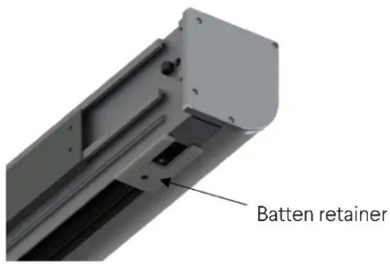
Figure 1. Luxus bottom view with batten retainer installed

Figure 2. Luxus rear view with batten retainer removed
PREPARING THE INSTALLATION (CONTINUED)
When installing your Luxus to the wall or ceiling using the sliding mount bracket, there are a couple things to consider to make the installation a smooth and easy operation.
Mounts

natural_image
Metal L-shaped metal beam with flanged ends and central notches (no text or symbols)Inside each Luxus box there are two 18 inch mounts to be used in whichever configuration that is required. Each mount has a total of six holes precut to ensure that at least two studs are utilized for mounting (see Figure 3). The spacing between the two edge holes is 16 inches.
Figure 3. Top of Luxus mount
Fasteners
The type of fasteners used for mounting is critical. If incorrect fasteners are used, the channels of the Luxus may not latch onto the mount clips. Additionally, if weak fasteners are used, the Luxus unit may fall. Be sure to use a total of four No. 10, 3 ½ inch deck screws on each mount (see Figure 4).

Figure 4. No. 10, 3 ½ inch screw
Professional mounting techniques should be used. Stewart Filmscreen cannot be liable for substandard or faulty installations. Failure to comply with the instructions and guidance contained in this manual may result in voiding your warranty.

CAUTION
Be careful not to touch or scratch the viewing surface.
Ensure wall surface is level and free of undulations. Use shimming if necessary.
- Identify the location of wall studs where you can secure the wall mounts.
-
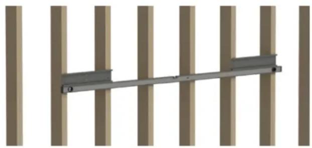
Use a level to accurately position the wall mounts on the wall (see Figure 5), and make certain that both wall mounts are within 24 inches from either edge of the case. This will prevent the case from tilting to either side.
-
Drill holes through the wall mounts into the studs.
-
Use 3 12 " screws to secure the wall mounts to the wall studs.
Note: These are heavy units. Wall mounts must be mounted to as many studs as possible (see Figure 5). Check to make sure the wall mount is level.
-
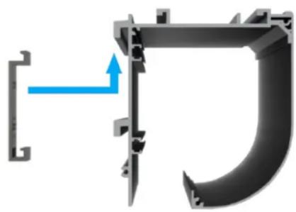
Carefully lift and hook the channels on the back of the housing onto the wall mounts (see Figure 6).
-
Ensure the housing channels are securely placed onto the hanging bar (see Figure 7).
-
For the minimum clearance dimensions, (see figure 8).

natural_image
Technical diagram of a wall-mounted bracket assembly with mounting hardware (no text or symbols)Stewart Filmscreen – Luxus
natural_image
Pure structural diagram of a metal beam supported by vertical columns, no text or symbols presentFigure 5. Wall mounts leveled and attached to one or more wall studs
natural_image
Mechanical component diagram showing a bracket with a blue arrow indicating direction (no text or symbols)Figure 6. Luxus case extrusion with wall mount
Figure 7. Back part of changing off wall mount

Figure 8. Wall mount detail with minimum clearance
Professional mounting techniques should be used. Stewart Filmscreen cannot be liable for substandard or faulty installations. Failure to comply with the instructions and guidance contained in this manual may result in voiding the warranty.
CAUTION
During installation, do not place the unit on an unstable cart, stand, table or ladder. The unit may fall, causing injury to you or others as well as cause possible damage to the unit.
Do not mount to drywall only. There must be wood joists behind the drywall to secure the screen.
- Use a magnetic stud finder, or similar appropriate means, to identify the location of solid ceiling joists. If the joists or rafters are parallel to the screen case, blocking is required between structural elements.
- Use a level or other straight edge to properly align both ceiling mounts as straight as possible.
- Screws must be mounted into solid wood. If no joists are available then the ceiling must be blocked.
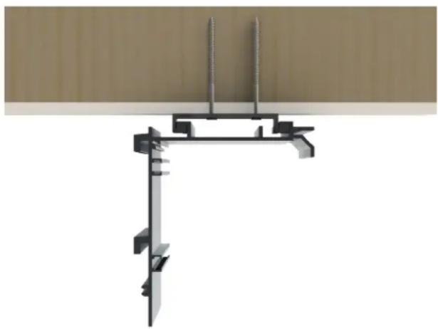
- Screw the ceiling brackets into the joists (see Figure 9). Ensure the screws are mounted to solid wood and that both ceiling brackets are properly aligned to each other.
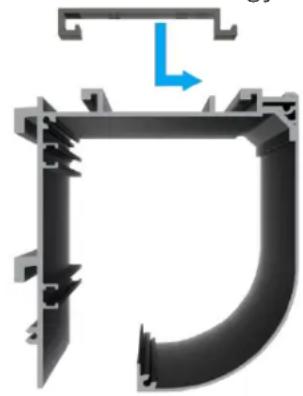
- Lift the case up to the ceiling and into the mounting brackets. Gently slide case backwards about 1/2" to engage and lock into brackets (see Figure 10).
- Since both mounts do not need to be equidistant to the sides of the case, you can float the case left and right to find the perfect position even after the screen is mounted.
- For the minimum clearance dimensions for both ceiling mount and soffit mount, (see Figure 11) and (see Figure 12) respectively.
natural_image
Architectural structural diagram showing vertical supports and beams (no text or symbols)Figure 9. Ceiling bracket screwed onto ceiling joists
natural_image
3D mechanical component diagram showing a U-shaped pipe with mounting brackets and a blue directional arrow (no text or symbols)Figure 10. Luxus case extrusion with ceiling mount extrusion

Figure 11. Ceiling mount detail with minimum clearance

Figure 12. Soffit mount detail with minimum clearance
The Luxus screen system can be controlled through several remote control devices (IR and RF), keypads, dry contact outputs, internet protocol (IP), and low-voltage trigger outputs.
CAUTION
Luxus is to be installed and used within the scope of the appropriate electrical codes and regulations. Failure to do so may cause malfunctioning or damage to the screen.
Note: This manual refers to AC (electrical alternating current) to represent electrical power. Your location may use 120 V, 220 V, or other electrical power. Screen systems are manufactured using the electrical power type specified for the location. Use appropriate power sources for your location.
MOTOR WIRING
The Luxus' screen system's motor is prewired at the factory. No additional motor wiring is required.
The following pages will outline standard and optional control types for Luxus.
CAUTION
Luxus has two female RJ45 inputs on rear of case. Neither port is to be used with POE (power over Ethernet). Improper use of ports will cause irreversible damage to IMC control board and may void your warranty.
Connections
The following Stewart Filmscreen accessories that plug into the smart port have RJ25 male connections. These accessories are able to plug into the RJ45 female smart port with no issues.
IR receiver
IR wall switch
IBT-100
IMC WITH IR RECEIVER AND REMOTE (STANDARD)
A 3-button IR (infrared) remote control (see Figure 13) is supplied for the IMC (see Figure 14). The IMC control board comes ready to be operated via IR and projector trigger right out of the box. You may visit StewartFilmscreen.com for a full list of IR Hex codes if you want to program the IR to another remote.

natural_image
White remote control device with three buttons (▲, ▼, *) and brand logo (Stewart) on the side (no readable text beyond branding)Figure 13. IR remote

natural_image
Electronic circuit board with components including a blue EEA brand, green connectors, and black/red capacitors (no visible text or symbols)Figure 14. IMC control system
GETTING STARTED
Making the Connections
- Connect the IR eye with RJ25 end to the back of Luxus on the smart port with RJ45 as shown (see Figure 15).
- Place the IR eye anywhere in the room, making sure that there are no obstructions between the eye and the screen.
Note: Luxus comes with two RJ45 female inputs. The maximum length of the RJ45/RJ25 cable plugged into the unit shall not exceed 50'. Dry closure modules from any home automation system can be interfaced, utilizing up/down/common type terminations only on the dry contact port.

Figure 15. Rear, audience left of case with 10 ft power wire, two RJ45 inputs and a 3.5 mm trigger port
IMC WITH IR RECEIVER AND REMOTE (CONTINUED)
OPERATION
After the screen has been properly mounted, check that the batten retainers have all been removed. Using the IR remote, press the “down” button and the Luxus screen will automatically extend fully to its preset limit and will power itself off. Press the “up” button once and the Luxus screen will automatically retract back into the case and power itself off. If a custom position is desired, simply press the “stop” button at any time during the screen’s deployment or retraction.
Note: See the section, "Adjusting Screen Deployment" (see Page 26), for information regarding the default limits to which the screen can be adjusted up or down from the factory preset.
12 VOLT PROJECTOR TRIGGER (STANDARD)
Two male, mono, 3.5mm auxiliary plugs are supplied so they can be used with the standard 12 volt projector trigger feature of the IMC. Since Stewart Filmscreen cannot be certain how long of a cable will be needed for every single application, the trigger cable will have to be assembled by the installer.
GETTING STARTED
Making the Connections
PROJECTOR TRIGGER
- Connect the straight, male, 3.5 mm (see Figure 16) projector trigger cable to the projector. Two male pieces, straight, and 90 degrees will be supplied for the installer to make a cable.
- Connect the 90 degree, male, 3.5 mm (see Figure 17) trigger cable to the Luxus unit's female 3.5 mm aux port (see Figure 15).
- Make sure to properly set up your projector to send a trigger signal. The screen should automatically roll down and roll up when the projector is powered on and powered off.
HOW IT WORKS
When a trigger-signal equipped projector is turned on or off, voltage is either supplied or withdrawn via a class II two-conductor wire (3.5mm aux cable) connected to the screen. The projector delivers between 5 and 12 volts when it is powered. The screen control (IMC) interprets this voltage as a prompt to deploy the screen. If there is a

natural_image
Close-up of a black plastic electrical plug with a metallic shaft (no text or symbols visible)Figure 16. Straight 3.5mm mono plug

natural_image
Close-up of a black plastic mechanical component with a metallic threaded shaft (no visible text or symbols)Figure 17. 90 degree 3.5mm mono plug
sudden change in voltage, the motor is paused for 12 of a second before reversing direction. This is to prevent strain on the motor mechanism and to prevent damage to any material controlled by the motor. When the projector and screen are energized, the control system relay is also energized. In the retracted position, relays are automatically de-energized after 120 seconds of operation to reduce power consumption.
RTS MOTOR OPERATION (IF EQUIPPED)
RTS MOTOR
The Somfy RTS motor is an advanced option that integrates well with most home automation systems through myLink. With a network connection, Amazon Alexa, Google Home, IFTTT – or by using the myLink app with your smart device – will allow control over your Stewart electric screen's RTS motor. Optionally, you can also purchase the RF remote to control your RTS motor.
Programming Mode
Before you begin
Motors are shipped without limit settings and transmitter ID's. Steps 1 to 7 must be completed to ensure proper shade programming and functionality. Power should ONLY be connected to current shade being programmed. All other shades should be disconnected from their respective power while programming
STEP 1: Connect power
With the motor installed in shade, connect power to the motor (120V, or 12 V or 24V transformer or 12 V battery wand)
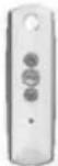
STEP 2: Initiate programming
Press both ⏚ and ⬆ at the same time until the shade jogs. A jog is a brief up and down motion. In Programming Mode, the shade will move only when the ⏚ or ⬆ is held

STEP 3: Check directions
Press ∧ or √. When pressing √ product should go down or out. To change direction press and hold (Stop) until the shade jogs. A jog is a brief up and down motion.
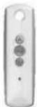
STEP 4: Set the limits
Bring the shade to desired upper limit stop point. Press both (Stop) and √ until the motor moves, then release. (If the shade stops when the buttons are released take it back to the upper limit and repeat) Stop the motor when reaching the desired lower limit. You can adjust by pressing ∧ or √

STEP 5: Set the limits
Press both (Stop) and at the same time until the shade moves, then release. The shade will stop at the original upper limit.

STEP 6: Confirm limit settings
Press and hold my (stop) until the shade jogs to confirm the limit settings. A jog is a brief up and down motion.
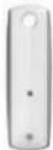
STEP 7: Set user mode
Press and hold the programming button on the back of the transmitter until the shade jogs. The shade is now in User Mode. In User Mode, the shade will operate with a brief press on ▲ or √ Double check limit settings as a precaution.
Adjusting the limits in User Mode

To change the lower limit
Send the shade to it's current lower limit.
To change the upper limit
Send the shade to it's current upper limit.

Press both ⬆ and ⬇ at the same time until the shade jogs. Adjust to a new lower limit position.
Press both ⬆ and √ at the same time until the shade jogs. Adjust to a new upper limit position.

until the shade jogs

until the shade jogs
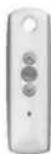
Adding or deleting a Transmitter or a Channel
Programmed Transmitter
STEP 1: Using already programmed transmitters select the transmitter (single channel) or the channel, (1-5) of a multi-channel transmitter.
STEP 2: Press and hold the programming button of that transmitter until the shade jogs.
Transmitter to add or delete
STEP 3: Select the transmitter (single channel) or the channel, (1–5) of a multi-channel transmitter, to be added or deleted.
STEP 4: Press and hold the programming button of that transmitter until the shade jogs.

IR WALL SWITCH AND REMOTE (IF EQUIPPED)
A 3-button IR (infrared) remote control (see Figure 13) is supplied in conjunction with the 3 button IR (infrared) wall switch (see Figure 18) for the IMC (see Figure 14). The IMC control board comes ready to be operated via IR and projector trigger right out of the box. You may visit StewartFilmscreen.com for a full list of IR Hex codes if you want to program the IR to another remote. Instead of receiving an IR receiver eye, you will get a wall switch with the eye built in.
GETTING STARTED
Making the Connections
- Connect the RJ25 cable to the back of the IR wall switch (see Figure 19).
- Connect the IR wall switch cable with RJ25 end to the back of Luxus on the smart port with RJ45 as shown (see Figure 15).
- Install the IR wall switch anywhere in the room, making sure that there are no obstructions between the eye and the screen.
- Keep note that you may want to hide the cable inside your wall to ensure a clean install.
Note: Luxus comes with two RJ45 female inputs. The maximum length of the RJ45/RJ25 cable plugged into the unit shall not exceed 50'. Dry closure modules from any home automation system can be interfaced, utilizing up/down/common type terminations only on the dry contact port.
OPERATION
After the screen has been properly mounted, check that the batten retainers have all been removed. Using the IR remote, press the “down” button and the Luxus screen will automatically extend fully to its preset limit and will power itself off. Press the “up” button once and the Luxus screen will automatically retract back into the case and power itself off. If a custom position is desired, simply press the "stop" button at any time during the screen's deployment or retraction.

Figure 1 &tFront of IR wall sw

natural_image
Green printed circuit board with labeled components including connectors, ports, and a 2012 label (no readable text beyond labels)Figure 19. Rear of IR wall switch with RJ25 input
Note: See the section, “Adjusting Screen Deployment” (see Page 26), for information regarding the default limits to which the screen can be adjusted up or down from the factory preset.
DECORA PADDLE WALL SWITCH (IF EQUIPPED)
A three position momentary wall switch (see Figure 20) can be equipped with the standard IMC control. The IMC control board comes ready to be operated via the Decora paddle wall switch right out of the box.
GETTING STARTED
Making the Connections
- Connect the RJ45/RJ25 cable to the back of the Luxus case on the dry contact RJ45 port (see Figure 15).
- Cut the other end of the wire and expose the four conductors.
- Connect your wires to the Decora wall switch (see Figure 21).
- For RJ45 pinouts (see Figure 23).

Figure 21. Rear of Decora Wall Switch

natural_image
Close-up of a white rectangular electronic device with metallic components and mounting holes (no visible text or symbols)Figure 20. Front of Decora Wall Switch
CAUTION
Decora wall switch is to be wired through the dry contact port only. The dry contact port is low voltage. Do not wire the wall switch through a high voltage line.
IBT-100 for Serial (RS-232C) CONNECTIVITY (IF EQUIPPED)
An IBT-100 can be equipped to plug in through the smart port on the back of the Luxus case. This unique piece of hardware combined with its integrated firmware and optional ancillary software can be used to interface CS-Bus controllers with external RS-232C networks to enable seamless bi-directional control and feedback.
GETTING STARTED
Making the Connections
- Connect the RJ25 cable to the back of the Luxus case on the smart port with RJ45 (see Figure 15).
- Connect the other side of the RJ25 cable to the RJ25 female port on the IBT-100 (see Figure 22).
- Connect your third party RS-232C connection to the female RS-232C port on the IBT-100.

Figure 22. IBT-100, showing RJ25 port
The method you use to raise and lower the screen depends on the type of control system and motor you have installed.

CAUTION
Be careful not to touch or scratch the screen's viewing surface.
Note: When you lower or retract the screen, it will stop at its preset limit. If an obstacle, such as a person or any furniture, is in the path of the screen as it is lowered, use the switch control to stop the screen's motion. The screen will not automatically stop if it hits an obstacle.
The motor is designed to be used for short operations such as lowering the screen in preparation for viewing. The motor is not designed for continuous duty. If the motor operates continually for more than a few minutes, it may automatically shut off to prevent damage from overheating. If the motor occasionally needs to be run more than normal, i.e., during initial setup and positioning, allow time for the motor to cool down.
In general, when the screen is not in use, you should store it in the fully retracted position to protect the screen's surface. It is best practice however, to deploy the screen for extended periods. Periodic deployment on a regular basis will maximize the flatness and uniformity of the screen's surface. The screen benefits from frequent and extended periods of deployment.

CAUTION
If the unit emits any smoke, heat, abnormal noise or unusual odor, the unit is most likely damaged in some way — such as damage from a water leak or power surge. Do not operate the motor if any of these situations occur. Call a qualified service person for assistance.
INTELLIGENT MOTOR CONTROL (IMC) WIRING
The IMC is a low voltage screen control that allows for switching conductors to be run in Class II (small wire, exposed, no conduit) and will interface with outboard video switching systems.
The IMC has the capability of being operated through a wall switch, infrared remote, radio frequency remote, internet protocol (IP) control system, and a screen trigger through a projector. The IMC is the most robust controller offered for Luxus. For a detailed look at what the IMC has on board, please see below (see Figure 23).
The IMC comes prewired from the factory to the motor and to the power cable. For your reference, in the case of servicing, we broke down the pin layout for the high voltage side of the connections (see Figure 24). Always have a qualified electrician handle high voltage connections.
| AC load side | IMC 100 | Motor Power Connectors |
| BLACK | Pin 1 | AC Line + |
| WHITE | Pin 2 | AC Neutral |
| NC | Pin 3 | Motor RED Line |
| NC | Pin 4 | Motor BLACK Line |
| NC | Pin 5 | Motor Neutral |
| GREEN | NC | Connect Ground to “Grounding” lug on IMC housing. Also connect ground wire from motor housing to same lug |

Figure 23. IMC control board schematic

Figure 24. High voltage pin schematic
| LVC Contacts | IMC 100 | COMMANDS |
| COMMON | Pin 1 | COMMON |
| CHANNEL 1 INPUT | Pin 2 | UP |
| CHANNEL 2 INPUT | Pin 3 | DOWN |
| SCREEN TRIGGER INPUT | Pin 4 | TRIGGER 3-15 VDC w/ COMMON |
INTELLIGENT MOTOR CONTROL (IMC) WIRING (CONTINUED)
The IMC can be wired to any dry contact wall switch (see Figure 25). If you would like one from Stewart Filmscreen, you may order as an option directly from us.

flowchart
graph TD
    A["120 VAC Plug"] --> B["+12 VDC Trigger Input (Green)"]
    B --> C["Common, -12 VDC Trigger Input (White)"]
    C --> D["Common 7 -12 VDC Trigg (White)"]
    D --> E["Up (Red)"]
    E --> F["Down (Black)"]
    F --> G["Down (Black)"]
    G --> H["Wall Switch"]
    H --> I["3 Conductor Hookup 20-24 GA (Not Supplied) Length TBD"]
    I --> J["Class II, 24 Volt Control Circuit"]
    J --> K["Remote INFRARED Sensor"]
    K --> L["IMC"]
    L --> M["Motor Motor"]
    L --> N["IMC and Motor Prewired at Factory"]
    style A fill:#f9f,stroke:#333
    style L fill:#ccf,stroke:#333
    style N fill:#cfc,stroke:#333
Figure 25. IMC Wiring Diagram
IMC RJ45 PINOUTS FOUND ON BACK OF CASE
All Stewart Filmscreen “smart port accessories” that are RJ25 will plug into the RJ45 smart port (see Figure 15) on the back of the Luxus case. In the box you will find two spare RJ45 connectors. These are provided for the ease of making or extending wires for use with dry contact port. If you need to interface your Luxus to a third party control or to a Decora wall switch, you must connect to the dry contact port (see Figure 15). Any dry contact connections must match the RJ45 pinout diagram (see Figure 26).
8 Pin RJ45 for Low Voltage Dry Contact Connector

Figure 26. RJ45 pinout diagram
CAUTION
Do not plug in any POE (power over Ethernet) devices into either the smart port or dry contact port. Irreversible damage to the IMC board will occur and your warranty may be void.
IMC SPECIFICATIONS
| Network (IP) Connection | Through separate (single) e-Node |
| RS-232c Connection | Through separate (single) IBT-100 |
| Compliance | ETL Listing to UL 325 , FCCA, CE, RoHS |
| Dimensions | .78" x 2.75" x 1.1" |

CAUTION
Please read and understand the following information. Improperly adjusted motor limit switches can result in irreparable damage to the projection screen or motor and will void your warranty.
These instructions refer to screens equipped with the IMC control unit only. For screens with the RTS motor, please refer to the respective RTS motor section (Page 17).
Stewart Filmscreen uses tubular Somfy motors in many of our projection screens. Users may require adjusting the limit switches at some point in time.
Tool required: 4 mm hex key or 5/32" hex driver. You can also use an electrician's 1/8^th inch flat blade screwdriver.
Note: Never use an electric drill or powered screwdriver to adjust Somfy motor limit switches as this will damage the internal timing assembly in the motor. The switches are designed for manual (by hand) incremental adjustment only.
ADJUSTING THE SCREEN'S DEPLOYED (DOWN) STOPPING POSITION
This is the number one adjustment that users may need to make. A projection screen may require that the deployed stopping position “white” switch be readjusted from the factory setting.
This adjustment will be made using the “white” limit switch (see Figure 27). It is important to remember that you cannot reduce the screen’s deployment setting when the screen is currently stopped at its full “down” setting. You must use the control switch to raise the screen up a foot or so before attempting a motor limit switch adjustment. If the screen is operated by a screen trigger, you must reduce this “white” limit switch when the screen is stopped in its fully retracted, “up” position. Turn the “down” motor limit switch clockwise to reduce top masking settings.
Turning the motor limit switch counterclockwise will increase or extend the screen's deployed stopping position. Switches are sensitive. Go slowly and do quarter turns at all times with the 5/32" hex driver to prevent damage to the motor and to the screen. Do not extend the screen so far that the aluminum roller tube becomes exposed. There must be at least one full wrap of the screen left on the roller tube when the screen is resting at its final deployed setting. If you turn this limit switch too much (clockwise) and the screen is now stopping short of where you want it, simply turn it in the opposite direction (counterclockwise) and the screen will automatically drop in increments as you rotate the switch.
ADJUST THE SCREEN'S RETRACTED (UP) STOPPING POSITION
CAUTION: Making adjustments to the yellow switch can inadvertently damage the screen or the motor if the fully retracted stopping position is set too high into the housing. This will cause the screen's batten bar to impact the screen roll and may cause optical damage to the screen. Improper adjustment can also cause the batten to jam into the housing which obstructs it from deploying when the "down" command is sent. Left in this position, the motor will fail due to overrun. Only qualified, experienced technicians should attempt to make adjustments to the "up" yellow limit switch (see Figure 27).
NOTE: Failure to follow these directions may result in voiding your warranty.

Figure 27. Lower Back View, audience left side of Luxus. Motor with yellow and white adjuster limits.
In the fully “up” retracted stopping position, the screen’s batten bar must hang freely underneath the screen roller tube. The batten bar cannot contact or press against the projection screen roll. Make sure to check and correctly adjust the yellow or “up” limit switch to avoid screen damage from a compacted batten bar. Switches are sensitive. Go slowly and do quarter turns at all times with the 5/32” hex driver to prevent damage to the motor and to the screen.
Counterclockwise adjustments of this switch will raise the batten bar and clockwise adjustments will lower the batten's top setting. Lowering the batten's top stopping position is valuable when trying to align the screen's batten with the bottom of the Luxus case.
CAUTION
Please remember that improperly adjusted motor limit switches will cause damage to your projection screen or motor. Make sure that both of the motor limit switches have been properly adjusted, allowing the projection screen to stop correctly at both the retracted and deployed positions.
Luxus now offers a two-piece construction that allows the bonnet (front fascia) to come off for servicing. This allows easy access to the control system and roller tube assembly without having to take the entire unit down. To remove the bonnet:
- Remove the four hex head 10-32 screws from each end cap, left and right (see Figure 28).

natural_image
Metal pipe fitting with rounded ends and mounting holes (no text or symbols visible)Figure 28. Audience left, front of unit, showing screws removed
- Remove both end caps as you undo the last screw from each side (see Figure 29).


natural_image
Interior view of a cylindrical electronic device with visible internal components (no text or symbols)Figure 29. Audience left, front of unit showing endcap removed
- Slide the bonnet off. Carefully place in a safe location (see Figure 30).

natural_image
3D rendering of a mechanical assembly with internal components and mounting bracket (no visible text or symbols)Figure 30. Audience left, front of unit, showing bonnet removed
Installation is the reverse of the uninstalling instructions.
With reasonable care, you may expect many years of dependable use of your Stewart projection screen.
GENERAL MAINTENANCE
The surface of your screen is delicate, so we encourage you to keep your screen clean. Special attention

CAUTION
- Oils and grease from hands can easily transfer to screen material.
➢ Be careful not to touch or scratch the viewing surface.
to these instructions should be followed when cleaning.
- Avoid getting any foreign objects on the screen as cleaning may prove very difficult. It may not be
possible to remove scratches, paint, ink, etc. - A draftsman-style brush may be used to lightly whisk away any loose dirt or dust particles. This type of brush is usually available at office supply stores. Stewart Filmscreen has an optional screen cleaning kit that contains the proper type of brush. Contact your dealer if you would like to obtain this cleaning kit (see Figure 31).
- For tougher spots, you can make a cleaning solution using a water-based detergent and warm water. To make the solution, mix one part Simple Green, 409, or other water-based industrial cleaner with three parts warm water. Moisten a clean cotton cloth or cotton swab with this solution, moisten the stained area, and gently lift off the stain. Never use an aggressive scrubbing action as you could damage the screen surface by removing the optical coating. Remoisten the area with clean water and dab dry with a clean sponge or cotton cloth. Any residual watermarks will evaporate on their own within minutes.
- Contact the factory if you have questions about removing difficult spots.
- If brushed aluminum endcaps were selected instead of painted endcaps, you may notice slight tarnishing of aluminum surface over time. If this happens, take a high quality microfiber towel and hand buff the tarnish away.

CAUTION
Do not use cleaners containing alcohol as they can damage the optical surface of the screen fabric.

natural_image
Product photo of Stewart cleaning kit components including brush, filter, and spray bottle (no text or symbols visible)Figure 31. Stewart Filmscreen Cleaning Kit
Refer to the following guidelines if you encounter any difficulty in the operation of your Stewart screen. Problems related to electrical or motor function may require a qualified service person or electrician. Should you have a problem that is not addressed below, please call Stewart Filmscreen at 1 (310-784-5300) or toll free 1 (800-762-4999) for assistance.
| Problem | Cause | Action Steps |
| The screen won't operate | No AC power available | Check to see if the circuit breaker has switched off. Reset if needed. Check the outboard switching apparatus. Check voltage availability. Contact an electrician |
| The screen won't roll up or down (even though power is available) | Bad connection at the switch. Polarity of IMC line may be bad | Have an electrician or qualified service person check control board connections |
| The screen roller chatters when power is activated | Can be caused by voltage drop, bad connections, or a defective switch | Have an electrician or qualified service person check all hookups including outboard wiring |
| The unit hums in “up” mode | The screen batten is retracting too far into the case. Failure to correct can damage the motor and the screen. Do not use the unit until this problem is resolved | Have a qualified service person adjust the yellow UP limit switch |
| The screen drops when “up” direction is activated | Could be a drop in voltage | Screen motor requires full voltage. Have an electrician or qualified service person check available voltage |
| The screen continues past bottom stop position | “White” limit switch is out of adjustment | Readjust the “white” down limit switch. See the section on Adjusting Screen Deployment of this manual (Page 24) |
| The batten retracts too far into case | “Yellow” limit switch is out of adjustment. Failure to correct can damage motor and screen. Do not use the unit until the problem is resolved | Have a qualified service person adjust the “yellow up” limit switch |
Stewart Filmscreen – Luxus
| The motor shuts off. The motor has been in use for more than 2 minutes | The motor is designed for short operations (lowering and retracting), not continuous duty. Longer operation causes the motor to overheat and shut off | Allow the motor to cool down. Complete cooling can take an hour or more. Heat gain is cumulative and takes time to dissipate. If motor use is initiated before it has cooled completely. The motor will shut down again when it reaches maximum temperature |
| Dirt, fingerprints, marks, etc., on the screen surface | Improper handling of screen | Lightly brush off or use a mild water-based detergent solution with a clean rag or cotton swab |
| Indentions appear on screen surface | Debris or particles adhering to screen due to static cling | Check back of screen; gently brush debris away with a soft brush |
| Brushed aluminum end caps on case appear dull in color | Aluminum finish may be tarnishing normally due to age and exposure | Take a clean high quality microfiber towel and hand buff aluminum endcaps to remove any tarnishing |
STEWART FILMSCREEN CORPORATION (Stewart) warrants all products to the original purchaser only. Stewart products are guaranteed to be free from defects in materials and workmanship for a period of one (1) year from the date of purchase by the original purchaser or eighteen (18) months from date of manufacture, as defined in the serial number. Additionally, all products must be properly operated and maintained according to Stewart instructions and cannot be damaged due to improper handling or treatment after shipment from the factory. This warranty does not apply to equipment showing evidence of misuse, abuse, or accidental damage, including neglect caused by improper installation (i.e. proximity to hot lights, exposure to extreme heat or cold, exposure to excessive humidity, etc.).
Stewart on-site warranty repair services are not available for this product. Stewart's sole obligation under this warranty shall be to repair or to replace (at Stewart's sole discretion) the defective part of the merchandise. This warranty expressly does not cover any costs of removal, installation, framing, or other costs incidental to replacing the screen or returning it to Stewart. Returns for service should be made to your Stewart dealer. If it is necessary for the dealer to return the screen or part to Stewart, transportation (freight) expenses to and from Stewart are payable by the purchaser. Stewart is not responsible for damage in shipment. To protect against damage or loss in transit, insure the product and prepay all transportation expenses.
This warranty is in lieu of all other warranties, expressed or implied, including warranties as to fitness for use or merchantability. Any implied warranties of fitness for use or merchantability, which may be mandated by statute or rule of law, are limited to the one (1) year warranty period. This warranty gives you specific legal rights, and you may also have other rights which vary from state to state. In no event will Stewart be liable for sums in excess of the purchase price of the product. No liability is assumed by Stewart for expenses or damages resulting from interruption in operation of equipment, or for incidental, direct, or consequential damages of any nature. In the event that there is a defect in materials or workmanship of a Stewart Filmscreen product, you may contact our customer service department at 1161 W Sepulveda Blvd, Torrance, CA 90502-2797, or call us at 1 (310) 784-5300, or toll free at 1 (800) 762-4999.
IMPORTANT: This warranty shall not be valid and Stewart shall not be bound by this warranty if the product is not operated and maintained in accordance with Stewart's written instructions. Stewart Filmscreen Corporation shall not be liable for any and all consequential damage(s) occasioned by the breach of any written or implied warranty pertaining to the sale of a Stewart Filmscreen product in excess of the purchase price of the product sold.
Stewart
F I L M S C R E E N
The Reference for Stunning™
www.StewartFilmscreen.com
1161 W. Sepulveda Blvd., Torrance CA 90502 USA | 800.762.4999 | Tel: 310.784.5300 | Fax: 310.326.6870 | Email: request@stewartfilmscreen.com
©2020 Stewart Filmscreen. Specifications are subject to change without notice.


- Printed in U.S.A. ©2021 Stewart Filmscreen Corporation
- Luxus
- OWNER'S MANUAL
- Contents
- NOTE
- IMPORTANT SAFETY INFORMATION
- USING THIS MANUAL FOR INSTALLATION
- SPECIFICATIONS
- Before beginning the installation
- What's inside the box?
- You will need
- CAUTION
- Unpacking
- PREPARING THE INSTALLATION (CONTINUED)
- Fasteners
- MOTOR WIRING
- Connections
- IMC WITH IR RECEIVER AND REMOTE (STANDARD)
- GETTING STARTED
- Making the Connections
- IMC WITH IR RECEIVER AND REMOTE (CONTINUED)
- OPERATION
- VOLT PROJECTOR TRIGGER (STANDARD)
- PROJECTOR TRIGGER
- HOW IT WORKS
- RTS MOTOR OPERATION (IF EQUIPPED)
- RTS MOTOR
- Programming Mode
- Before you begin
- STEP 1: Connect power
- STEP 2: Initiate programming
- STEP 3: Check directions
- STEP 4: Set the limits
- STEP 5: Set the limits
- STEP 6: Confirm limit settings
- STEP 7: Set user mode
- Adjusting the limits in User Mode
- To change the lower limit
- To change the upper limit
- Adding or deleting a Transmitter or a Channel
- Programmed Transmitter
- Transmitter to add or delete
- IR WALL SWITCH AND REMOTE (IF EQUIPPED)
- DECORA PADDLE WALL SWITCH (IF EQUIPPED)
- IBT-100 for Serial (RS-232C) CONNECTIVITY (IF EQUIPPED)
- INTELLIGENT MOTOR CONTROL (IMC) WIRING
- INTELLIGENT MOTOR CONTROL (IMC) WIRING (CONTINUED)
- IMC RJ45 PINOUTS FOUND ON BACK OF CASE
- ADJUSTING THE SCREEN'S DEPLOYED (DOWN) STOPPING POSITION
- ADJUST THE SCREEN'S RETRACTED (UP) STOPPING POSITION
- GENERAL MAINTENANCE
Brand : Stewart
Model : Luxus
Category : Projection screen