GCV04 - Vacuum Cleaner MAKITA - Free user manual and instructions
Find the device manual for free GCV04 MAKITA in PDF.

User questions about GCV04 MAKITA
0 question about this device. Answer the ones you know or ask your own.
Ask a new question about this device
Download the instructions for your Vacuum Cleaner in PDF format for free! Find your manual GCV04 - MAKITA and take your electronic device back in hand. On this page are published all the documents necessary for the use of your device. GCV04 by MAKITA.
USER MANUAL GCV04 MAKITA
Cordless Vacuum Cleaner Aspiradora Inalámbrica
GCV02 GCV04
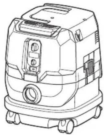
natural_image
Line drawing of a portable industrial vacuum cleaner with control panel and wheels (no text or symbols)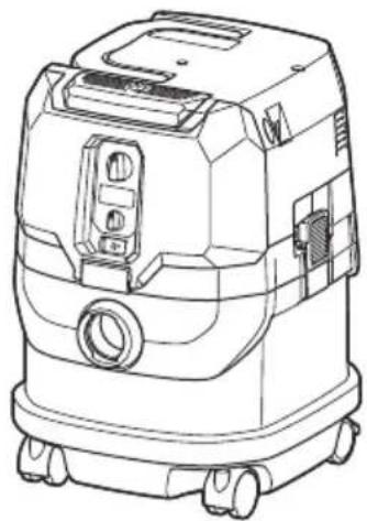
natural_image
Line drawing of a mobile industrial vacuum cleaner (no text or symbols)SPECIFICATIONS
| Model: GCV02 GCV04 | ||
| Standard filter type Powder filter (for dry dust) | ||
| Maximum air volume (with BL4040, ø38 mm (1-1/2") x 2.5 m (98-1/2") hose) | 2.7 m^3/min (95.35 cu.ft/min) | |
| Vacuum (with BL4040, ø38 mm (1-1/2") x 2.5 m (98-1/2") hose) 23 kPa | ||
| Recoverable capacity 8 L (2.1 gal.) 15 L (4.0 gal.) | ||
| Dimensions (L x W x H) 366 mm x 334 mm x 425 mm | (14-3/8" x 13-1/8" x 16-3/4") | 366 mm x 334 mm x 475 mm(14-3/8" x 13-1/8" x 18-3/4") |
| Rated voltage D.C. 36 V - 40 V max | ||
| Net weight 8.3 - 10.2 kg (18.3 - 22.5 lbs) 8.6 - 10.5 kg (19.0 - 23.1 lbs) | ||
- Due to our continuing program of research and development, the specifications herein are subject to change without notice.
- Specifications and battery cartridge may differ from country to country.
- The weight does not include accessories but battery cartridge(s). The lightest and heaviest combination weight of the appliance and battery cartridge(s) are shown in the table.
- For wet dust, the float and the water filter or cloth filter are required.
Applicable battery cartridge and charger
| Battery cartridge BL4020 / BL4025 / BL4040* / BL4050F* | *: Recommended battery |
| Charger | DC40RA / DC40RB / DC40RC |
- Some of the battery cartridges and chargers listed above may not be available depending on your region of residence.
⚠ WARNING: Only use the battery cartridges and chargers listed above. Use of any other battery cartridges and chargers may cause injury and/or fire.
SAFETY WARNINGS
IMPORTANT SAFETY INSTRUCTIONS
When using an electrical appliance, basic precautions should always be followed, including the following:
READ ALL INSTRUCTIONS BEFORE USING THIS APPLIANCE.
WARNING
To reduce the risk of fire, electric shock or injury:
- Do not leave appliance when battery fitted. Remove battery from appliance when not in use and before servicing.
- Do not use on wet surfaces. Do not expose to rain. Store indoors.
- Do not allow to be used as a toy. Close attention is necessary when used by or near children.
- Use only as described in this manual. Use only manufacturer's recommended attachments.
-
Do not use with damaged battery. If appliance is not working as it should, has been dropped, damaged, left outdoors, or dropped into water, return it to a service center.
-
Do not handle battery or appliance with wet hands.
- Do not put any object into openings. Do not use with any opening blocked; keep free of dust, lint, hair, and anything that may reduce air flow.
- Keep hair, loose clothing, fingers, and all parts of body away from openings and moving parts.
- Turn off all controls before removing the battery cartridge.
- Use extra care when cleaning on stairs.
- Do not use to pick up flammable or combustible liquids, such as gasoline, or use in areas where they may be present.
- Use only the charger supplied by the manufacturer to recharge.
- Do not pick up anything that is burning or smoking, such as cigarettes, matches, or hot ashes.
- Always make sure that filters are correctly installed before use. Do not use the cleaner without filters in place. Replace a damaged filter immediately. It is recommended to have some spares as filters are consumable items.
- Do not charge the battery outdoors.
- Do not use the cleaner as a stool or work bench. The machine may fall down and may result in personal injury.
- Do not pick up foam or soapy liquid. It can cause foam to come out of air exit, resulting in electric shock and damage to the cleaner.
-
Do not vacuum the following:
-
Flammable liquid (kerosene, gasoline, solvents such as benzine, thinner, etc.)
- Hot substances that are burning or smoking (cigarettes, matches, incense sticks, candles, hot ashes), sparks and metal dust generated by cutting or grinding metal, etc.
-
Flammable material (toner, paint, spray, etc.)
• Foam like carpet cleaning agent, etc. (they may cause explosion or fire) -
Explosive or pyrophoric substances (nitroglycerin, aluminum, magnesium, titanium, zinc, red phosphorus, yellow phosphorus, celluloid, etc. and their dust, gas or steam)
- Sharp objects (glass, cutlery, wood splinter, metal, stone, nail, razor, push pin, etc.)
• Solidifying and conductive fine powder (metal or carbon powder) - Dehumidifier
• Large amount of powder (flour, fire extinguisher powder, etc.) - Substances that cause toxic symptoms
- Aggressive chemicals (acid, leach, etc.)
- Liquid or damp garbage, including vomit and excreta
- Asbestos
- Pesticides
Such action may cause fire, injury and/or property damage.
To reduce your exposure to these chemicals, always wear approved respiratory protection such as dust masks that are specially designed to filter out microscopic particles.
Direct the exhaust air away from your face and body.
NOTE: Read the OSHA regulation on silica dust to understand the requirements needed to reduce exposure to silica dust at the job-site. Specific rules apply to the drilling, demolition cutting and grinding materials that contain silica. All OSHA requirements regarding reducing silica dust can be found at the OSHA website: www.osha.gov.
Battery tool use and care
-
Prevent unintentional starting. Ensure the switch is in the off-position before connecting to battery pack, picking up or carrying the appliance. Carrying the appliance with your finger on the switch or energizing appliance that have the switch on invites accidents.
-
Disconnect the battery pack from the appliance before making any adjustments, changing accessories, or storing appliance. Such preventive safety measures reduce the risk of starting the appliance accidentally.
- Recharge only with the charger specified by the manufacturer. A charger that is suitable for one type of battery pack may create a risk of fire when used with another battery pack.
- Use appliances only with specifically designated battery packs. Use of any other battery packs may create a risk of injury and fire.
- When battery pack is not in use, keep it away from other metal objects, like paper clips, coins, keys, nails, screws or other small metal objects, that can make a connection from one terminal to another. Shorting the battery terminals together may cause burns or a fire.
- Under abusive conditions, liquid may be ejected from the battery; avoid contact. If contact accidentally occurs, flush with water. If liquid contacts eyes, additionally seek medical help. Liquid ejected from the battery may cause irritation or burns.
- Do not use a battery pack or appliance that is damaged or modified. Damaged or modified batteries may exhibit unpredictable behavior resulting in fire, explosion or risk of injury.
- Do not expose a battery pack or appliance to fire or excessive temperature. Exposure to fire or temperature above 130 °C may cause explosion.
-
Follow all charging instructions and do not charge the battery pack or appliance outside of the temperature range specified in the instructions. Charging improperly or at temperatures outside of the specified range may damage the battery and increase the risk of fire.
-
Have servicing performed by a qualified repair person using only identical replacement parts. This will ensure that the safety of the product is maintained.
- Do not modify or attempt to repair the appliance or the battery pack except as indicated in the instructions for use and care.
SAVE THESE INSTRUCTIONS.
This appliance is intended for commercial use.
Symbols
The followings show the symbols used for tool.
| v | volts |
| — | direct current |
| ⚠️ | Take particular care and attention. |
| ### | Never stand on the cleaner. |
Important safety instructions for battery cartridge
- Before using battery cartridge, read all instructions and cautionary markings on (1) battery charger, (2) battery, and (3) product using battery.
- Do not disassemble or tamper the battery cartridge. It may result in a fire, excessive heat, or explosion.
- If operating time has become excessively shorter, stop operating immediately. It may result in a risk of overheating, possible burns and even an explosion.
-
If electrolyte gets into your eyes, rinse them out with clear water and seek medical attention right away. It may result in loss of your eyesight.
-
Do not short the battery cartridge:
(1) Do not touch the terminals with any conductive material.
(2) Avoid storing battery cartridge in a container with other metal objects such as nails, coins, etc.
(3) Do not expose battery cartridge to water or rain.
A battery short can cause a large current flow, overheating, possible burns and even a breakdown.
- Do not store and use the tool and battery cartridge in locations where the temperature may reach or exceed 50 °C (122 °F).
- Do not incinerate the battery cartridge even if it is severely damaged or is completely worn out. The battery cartridge can explode in a fire.
- Do not nail, cut, crush, throw, drop the battery cartridge, or hit against a hard object to the battery cartridge.
Such conduct may result in a fire, excessive heat, or explosion.
- Do not use a damaged battery.
- The contained lithium-ion batteries are subject to the Dangerous Goods Legislation requirements.
For commercial transports e.g. by third parties, forwarding agents, special requirement on packaging and labeling must be observed.
For preparation of the item being shipped, consulting an expert for hazardous material is required.
Please also observe possibly more detailed national regulations.
Tape or mask off open contacts and pack up the battery in such a manner that it cannot move around in the packaging.
- When disposing the battery cartridge, remove it from the tool and dispose of it in a safe place. Follow your local regulations relating to disposal of battery.
-
Use the batteries only with the products specified by Makita. Installing the batteries to non-compliant products may result in a fire, excessive heat, explosion, or leak of electrolyte.
-
If the tool is not used for a long period of time, the battery must be removed from the tool.
- During and after use, the battery cartridge may take on heat which can cause burns or low temperature burns. Pay attention to the handling of hot battery cartridges.
- Do not touch the terminal of the tool immediately after use as it may get hot enough to cause burns.
- Do not allow chips, dust, or soil stuck into the terminals, holes, and grooves of the battery cartridge. It may result in poor performance or breakdown of the tool or battery cartridge.
- Unless the tool supports the use near high-voltage electrical power lines, do not use the battery cartridge near a high-voltage electrical power lines. It may result in a malfunction or breakdown of the tool or battery cartridge.
- Keep the battery away from children.
SAVE THESE INSTRUCTIONS.
CAUTION: Only use genuine Makita batteries. Use of non-genuine Makita batteries, or batteries that have been altered, may result in the battery bursting causing fires, personal injury and damage. It will also void the Makita warranty for the Makita tool and charger.
Tips for maintaining maximum battery life
- Charge the battery cartridge before completely discharged. Always stop tool operation and charge the battery cartridge when you notice less tool power.
- Never recharge a fully charged battery cartridge. Overcharging shortens the battery service life.
- Charge the battery cartridge with room temperature at 10 °C - 40 °C ( 50 °F - 104 °F ). Let a hot battery cartridge cool down before charging it.
- When not using the battery cartridge, remove it from the tool or the charger.
- Charge the battery cartridge if you do not use it for a long period (more than six months).
Important safety instructions for wireless unit
- Do not disassemble or tamper with the wireless unit.
- Keep the wireless unit away from young children. If accidentally swallowed, seek medical attention immediately.
- Use the wireless unit only with Makita tools.
- Do not expose the wireless unit to rain or wet conditions.
- Do not use the wireless unit in places where the temperature exceeds 50 °C ( 122 °F ).
- Do not operate the wireless unit in places where medical instruments, such as heart pace makers are nearby.
- Do not operate the wireless unit in places where automated devices are nearby. If operated, automated devices may develop malfunction or error.
- Do not operate the wireless unit in places under high temperature or places where static electricity or electrical noise could be generated.
- The wireless unit can produce electromagnetic fields (EMF) but they are not harmful to the user.
- The wireless unit is an accurate instrument. Be careful not to drop or strike the wireless unit.
- Avoid touching the terminal of the wireless unit with bare hands or metallic materials.
- Always remove the battery on the product when installing the wireless unit into it.
- When opening the lid of the slot, avoid the place where dust and water may come into the slot. Always keep the inlet of the slot clean.
- Always insert the wireless unit in the correct direction.
- Do not press the wireless activation button on the wireless unit too hard and/or press the button with an object with a sharp edge.
- Always close the lid of the slot when operating.
- Do not remove the wireless unit from the slot while the power is being supplied to the tool. Doing so may cause a malfunction of the wireless unit.
- Do not remove the sticker on the wireless unit.
- Do not put any sticker on the wireless unit.
- Do not leave the wireless unit in a place where static electricity or electrical noise could be generated.
- Do not leave the wireless unit in a place subject to high heat, such as a car sitting in the sun.
-
Do not leave the wireless unit in a dusty or powdery place or in a place corrosive gas could be generated.
-
Sudden change of the temperature may bedew the wireless unit. Do not use the wireless unit until the dew is completely dried.
- When cleaning the wireless unit, gently wipe with a dry soft cloth. Do not use benzine, thinner, conductive grease or the like.
- When storing the wireless unit, keep it in the supplied case or a static-free container.
- Do not insert any devices other than Makita wireless unit into the slot on the tool.
- Do not use the tool with the lid of the slot damaged. Water, dust, and dirt come into the slot may cause malfunction.
- Do not pull and/or twist the lid of the slot more than necessary. Restore the lid if it comes off from the tool.
- Replace the lid of the slot if it is lost or damaged.
SAVE THESE INSTRUCTIONS.
PARTS DESCRIPTION
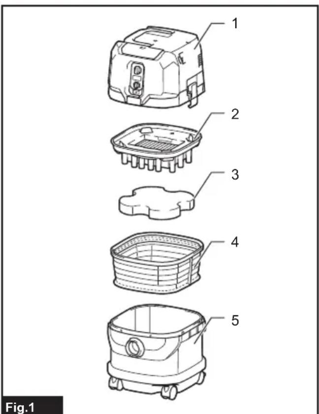
text_image
Fig.1▶ 1. Head unit 2. Powder filter (HEPA) 3. Damper 4. Prefilter 5. Tank
FUNCTIONAL DESCRIPTION
⚠️CAUTION: Always be sure that the appliance is switched off and the battery cartridges are removed before adjusting or checking function on the appliance.
Installing or removing battery cartridge
⚠️CAUTION: Always switch off the appliance before installing or removing battery cartridges.
⚠️CAUTION: Hold the cleaner and battery cartridges firmly when installing or removing battery cartridges. Failure to do so may cause them to slip off your hands, resulting in damage to the cleaner and battery cartridges or personal injury.
⚠CAUTION: Be careful not to pinch your fingers when opening or closing the battery cover. Failure to do so may cause personal injury.
The cleaner has double battery slots. With two identical batteries in parallel, you can extend your running time in one or more uses without having to stop to recharge batteries. The cleaner also works with a single battery, so you can choose with either double batteries or single battery according to your needs.
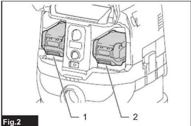
text_image
Fig.2 1 2▶ 1. Left battery slot 2. Right battery slot
With double batteries
Continuous drive with two batteries allows longer run-time and more efficient cleaning. When the first battery is becoming empty, the cleaner automatically switches a power source, so it continues working with the second battery.
NOTE: The left battery slot (when facing the front of the cleaner) has priority over the right battery slot. The right battery slot will only be identified as a power source, either when no battery is installed in the left battery slot or the battery in the left battery slot becomes empty.
NOTE: You can remove the battery from the left battery slot and recharge it after the cleaner has switched its power source from the left battery slot to the right without ceasing operation. To give priority back to the left battery slot after installing a recharged battery, restart the cleaner.
With a single battery
Only one battery is required as a power source in either the left or right battery slot. The cleaner automatically determines which battery slot is available according to operating conditions.
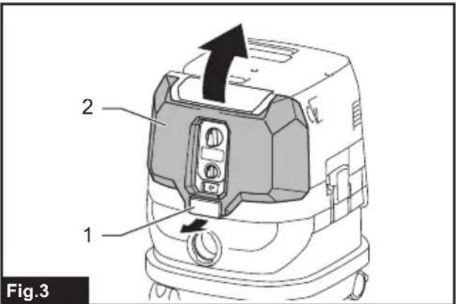
Installation and uninstallation
To install battery cartridges, release the lock first, and open the battery cover. Then insert the battery cartridges.
text_image
2 1 Fig.3▶ 1. Lock 2. Battery cover
Align the tongues on the battery cartridges with the grooves in the battery housing and slip them into place. Insert them all the way until they lock in place with a little click.
Then lock the battery cover.
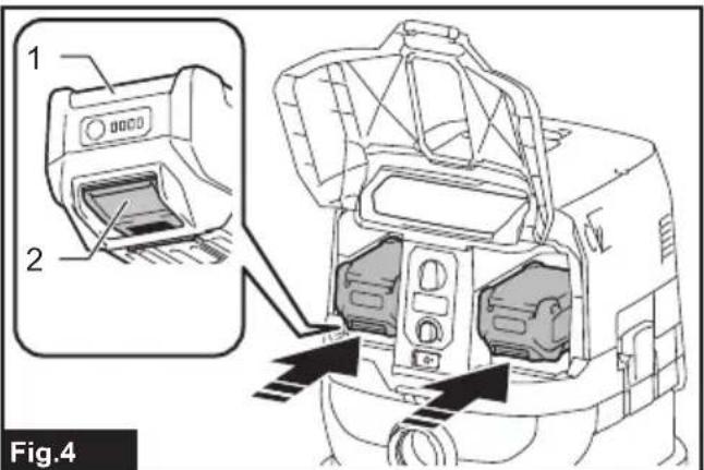
text_image
1 2 Fig.4▶ 1. Battery cartridge 2. Button
To remove the battery cartridges, slide them out of the battery housing while pressing and holding the buttons in front of the cartridges.
CAUTION: Always install the battery cartridge fully. If not, it may accidentally fall out of the appliance, causing injury to you or someone around you.
CAUTION: Do not install the battery cartridge forcibly. If the cartridge does not slide in easily, it is not being inserted correctly.
NOTE: When the cleaner switches the power source from the first battery to the second, it may require a temporary halt in operations, causing a slight loss of suction. Please note that it is not malfunction so the cleaner recovers and resumes operations immediately after the pause.
Indicating the remaining battery capacity
Press the check button on the battery cartridge to indicate the remaining battery capacity. The indicator lamps light up for a few seconds.

text_image
Fig.5▶ 1. Indicator lamps 2. Check button
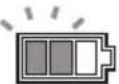
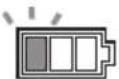
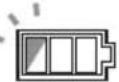
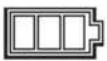
| Indicator lamps Remaining | capacity | ||
| Lighted Off | Blinking | ||
| 75% to 100% | |||
| 50% to 75% | |||
| 25% to 50% | |||
| 0% to 25% | |||
| Charge the battery. | |||
| The battery may have malfunctioned. | |||
NOTE: Depending on the conditions of use and the ambient temperature, the indication may differ slightly from the actual capacity.
NOTE: The first (far left) indicator lamp will blink when the battery protection system works.
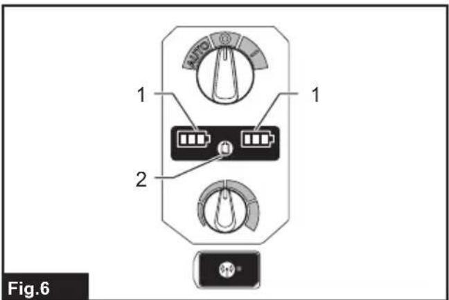
Battery indicators on control panel
The remaining battery capacity can be read on the control panel at any time. Press the check button, and the left and right indicators will show the battery charge levels correspondingly.
text_image
1 2 Fig.6▶ 1. Battery indicators 2. Check button
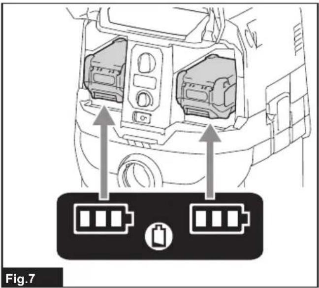
text_image
Fig.7| Battery indicator status Remaining | battery capacity | ||
| On | Off | Blinking | |
 | 50% to 100% | ||
 | 20% to 50% | ||
 | 0% to 20% | ||
 | Charge the battery | ||
 | Battery not inserted | ||
NOTE: The battery indicators will also be activated when the cleaner starts functioning or switches its power source from one to another.
Appliance / battery protection system
The appliance is equipped with an appliance/battery protection system. This system automatically cuts off power to the motor to extend appliance and battery life. The appliance will automatically stop during operation if the appliance or battery is placed under one of the following conditions:
Overload protection
When the appliance/battery is operated in a manner that causes it to draw an abnormally high current, the appliance automatically stops. In this situation, turn the appliance off and stop the application that caused the appliance to become overloaded. Then turn the appliance on to restart.
Overheat protection

text_image
On BlinkingWhen the appliance is overheated, the appliance stops automatically, and both left and right battery indicators blink. In this situation, let the appliance cool down before turning the appliance on again.

text_image
On BlinkingWhen the battery is overheated, the appliance stops automatically, and one of the indicators for overheated battery blinks. In this situation, let the battery cool down before turning the appliance on again.
Overdischarge protection
When the battery capacity becomes low, the appliance stops automatically. If the appliance does not run along with the switch operation, remove the batteries from the appliance and recharge them.
Protections against other causes
Protection system is also designed for other causes that could damage the appliance and allows the appliance to stop automatically. Take all the following steps to clear the causes, when the appliance has been brought to a temporary halt or stop in operation.
- Turn the appliance off, and then turn it on again to restart.
- Charge the battery(ies) or replace it/them with recharged battery(ies).
- Let the appliance and battery(ies) cool down.
If no improvement can be found by restoring protection system, then contact your local Makita Service Center.
Switch action
Turning cleaner on
- Turn the stand-by switch in the "I" (ON) or "AUTO" (ON) position to have the cleaner ready in stand-by mode.
- Press the power button. To switch back to stand-by mode, press the power button again.
Turning cleaner off
Perform one of the following steps.
- Press the power button to set the cleaner back in stand-by mode, and then turn the stand-by switch in the "O" (OFF) position.
- Turn the stand-by switch in the "O" (OFF) position.
Adjusting suction power
The suction power can be adjusted according to your work needs.
- Turn the suction force adjusting knob to the left to reduce the suction power.
- Turn the suction force adjusting knob to the right to increase the suction power.
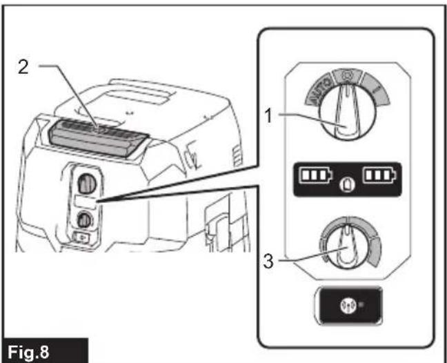
text_image
2 1 3 Fig.8▶ 1. Stand-by switch 2. Power button 3. Suction force adjusting knob
Locking and unlocking casters
Rear casters can be locked with stoppers to help the cleaner stand still.
Lower the stopper lever by hand to lock the caster, and raise it up to release.
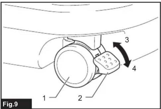
text_image
Fig.9 1 2 3 4▶ 1. Caster 2. Stopper lever 3. Unlocked position 4. Locked position
NOTE: When moving the cleaner, make sure that the caster is unlocked. Moving the cleaner with the caster in a locked position may cause damage to the caster.
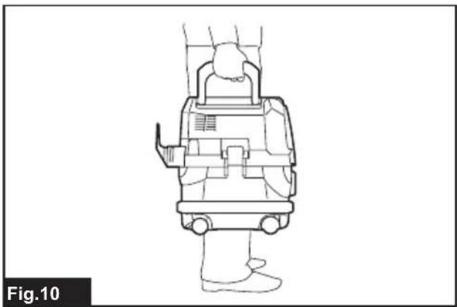
Carriage handle
⚠️CAUTION: Lift and carry the appliance with due care. Failing to do so may result in personal injury or damage to the appliance.
When carrying the cleaner, carry it by holding the handle on the head unit. The handle is retractable on the head unit when not in use.
natural_image
Line drawing of a person wearing a medical device, viewed from the side (no text or symbols)ASSEMBLY
⚠️CAUTION: Always be sure that the appliance is switched off and the battery cartridges are removed before carrying out any work on the appliance.
⚠️CAUTION: Always wear dust mask during assembly or maintenance.
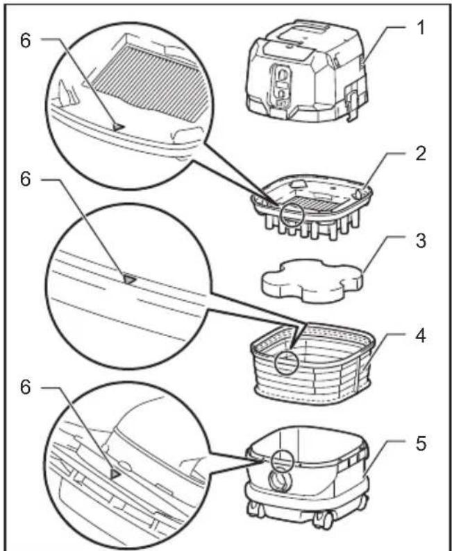
Installing powder filter (HEPA) and prefilter (for dry dust)
CAUTION: Never pick up water or other liquids or wet dusts when using the powder filter. Picking up such things may cause the powder filter breakage.
To use powder filter:
- Place the prefilter into the tank aligning the mounting position markings on the prefilter and tank.
-
Set the damper into the prefilter, and then place the powder filter over the damper aligning the mounting position markings on the powder filter and prefilter.
-
Mount the head unit over the tank and secure them with the locking latches.
text_image
Technical diagram showing exploded views of a car interior with numbered components and structural details.Fig.11
▶ 1. Head unit 2. Powder filter (HEPA) 3. Damper 4. Prefilter 5. Tank 6. Mounting position marking
NOTICE: Before using the powder filter, make sure that prefilter and damper are used together. It is not allowed to install powder filter alone.
Installing paper pack
Optional accessory
WARNING: Before using a paper pack, make sure that the prefilter is used together. Failure to use the prefilter together may cause unusual noise and heat, resulting in a fire.
NOTICE: Never pick up water or other liquids or wet dusts when using a paper pack. Picking up such things may cause the paper pack breakage.
NOTICE: Before using a paper pack, make sure that the powder filter, damper and prefilter are always used together.
- Unfold a paper pack.
-
Align the paper pack opening with the dust intake of the tank.
-
Install the paper pack into the tank with its cardboard opening hooked on the paper pack holder.
text_image
Technical diagram of a robotic device with numbered components and an inset view showing a close-up of the internal structure.Fig.12
▶ 1. Paper pack 2. Cardboard opening 3. Paper pack holder 4. Dust intake
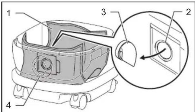
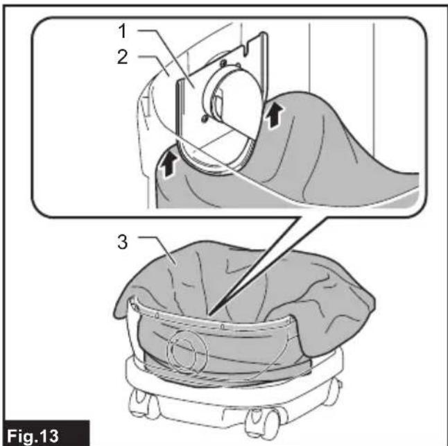
Installing polyethylene bag
With a polyethylene bag installed in the tank, you can easily empty the tank without letting your hands dirty.
Lay a polyethylene bag over the tank, and slip one side of the top edge of the bag at its open end in between the holder plate and the front wall of the tank.
text_image
1 2 3 Fig.13▶ 1. Holder plate 2. Front wall of tank 3. Polyethylene bag
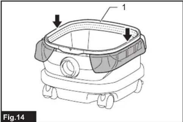
Spread the other top edges of the bag outwards over the top rims of the tank. Place the prefilter over the polyethylene bag to fasten the opening of the bag securely.
natural_image
Technical line drawing of a robotic device with labeled components (no text or symbols beyond labels)1.
NOTE: A polyethylene bag available on the market can be used. 0.04 mm or thicker one is recommended.
NOTE: Too much dust will tear the bag easily, so do not collect the dust more than the half of the bag capacity.
Emptying tank with polyethylene bag
WARNING: Always make sure that the cleaner is switched off and the battery cartridges are removed before emptying the tank. Failure to do so may cause an electric shock and serious personal injury.
NOTICE: Do not apply a great impact on the tank. Applying a great impact may cause deformation and damage to the parts.
NOTICE: Empty the tank at least once a day although this depends on picked-up dust volume in the tank. Or, the suction force will weaken and the motor may be broken.
NOTICE: Do not grab the hooks or latches when emptying the tank. Grabbing the hooks or latches may cause them to break.
Release the locking latches and lift the head unit up off the tank. Shake off dust from the prefilter before lifting the filter away from the tank.
Then remove the polyethylene bag out of the tank, closing the opening of the bag by hand.

text_image
1 2 Fig.151.
- Polyethylene bag 2. Tank
NOTE: Take the polyethylene bag out of the tank carefully to avoid it from being scratched and torn by the edges inside the tank.
NOTE: Empty the polyethylene bag before it becomes full. Too much dust in the tank may cause the polyethylene bag to be torn.
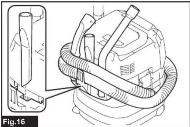
Installing multi hook
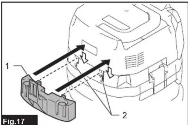
Use the multi hook to hold a hose, accessories and attachments not in use in place, and you can quickly take them out according to your preferences.
natural_image
Technical line drawing of a mechanical device with hoses and connectors, labeled Fig.16 (no text or symbols on the diagram itself)Place the multi hook over the mounting base at the rear of the cleaner, setting the rails on the multi hook along the grooves on the mounting base.
text_image
Fig.17 1 2▶ 1. Multi hook 2. Mounting base
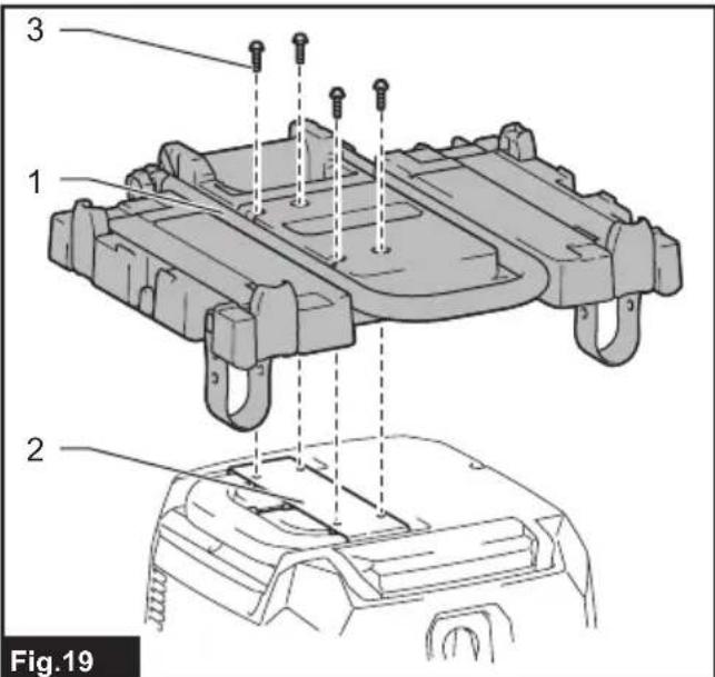
Installing MAKPAC adapter
Optional accessory
Connectable and stackable MAKPAC storage cases can be installed on top of the cleaner with an optional adapter. The cases are available in many sizes and styles to suit your preferences.
Place the mounting base hook over the handle of the cleaner with its mounting surface facing upwards when the handle is folded into the closed position.

text_image
Fig.18- Mounting base hook 2. Mounting surface 3. Handle
Mount the MAKPAC adapter onto the mounting base hook, and secure them together with four screws provided.
text_image
3 1 2 Fig.19▶ 1. MAKPAC adapter 2. Mounting base hook 3. Screw
Lift the push bar up and tighten the knob to prepare installing the MAKPAC cases onto the cleaner.

text_image
Fig.20 1 2- Push bar 2. Knob
NOTE: For details on installing the MAKPAC cases, refer to the instructions provided with the MAKPAC adapter and cases.
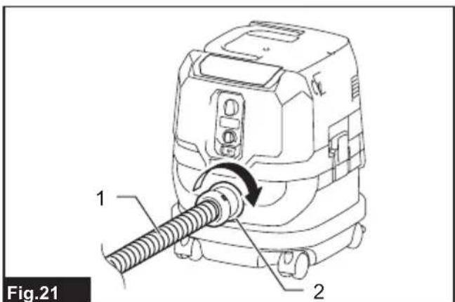
Installing hose
NOTICE: Never force the hose for bending or stamp it. Never move the cleaner by pulling the hose. Forcing, stamping and pulling the hose may cause a breakage or deformation of the hose.
NOTICE: When picking up large wastes such as planer carvings, concrete dusts or similar other than small wastes, use the 38 mm inner diameter hose (optional accessory). Using the 28 mm inner diameter hose (optional accessory) may cause a hose stuffing and damage.
Connection to cleaner
Insert the hose end to the dust intake (hose inlet) of the cleaner, then turn it clockwise until it locks in place.
text_image
Fig.21 1 2- Hose 2. Dust intake (hose inlet)
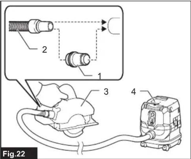
Connections with your work tools (Country specific)
By connecting the vacuum cleaner to any available work tools compatible with the cleaner, it works as a dust extractor for your power tools.
Select one of the front cuffs or joints (optional accessories) as most suitable for your tool model. Place the cuffs or joint, as necessary, between the front end of the cleaner hose and a dust extraction port of your tool.
text_image
Fig.22▶ 1. Front cuffs or joint 2. Cleaner hose 3. Power tool 4. Vacuum cleaner
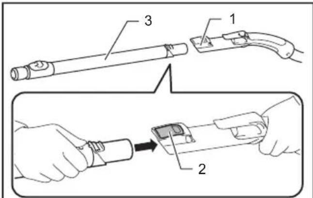
Installing or removing cleaner attachments
⚠CAUTION: After installing an attachment, check if it is securely installed. If the attachment is installed imperfectly, it may come off and cause personal injury.
Attachments without lock function
Optional accessory
Insert an attachment into the suction inlet of the cleaner by pushing and hand screwing it in place. Hand twist and pull the attachment apart from the suction inlet after use.

text_image
Fig.23Attachments with lock function
Optional accessory
NOTICE: When installing the attachment with lock function, be sure to align the release button with the hook on the attachment. If they are not aligned, the attachment will not be locked and may come off from the cleaner.
Insert an attachment into the suction inlet of the cleaner by pushing them together with a click.
To remove the attachment, pull it off while pushing the release button.
text_image
Technical diagram showing a tool being inserted into a device, with labeled parts 1, 2, and 3.Fig.24
- Suction inlet with lock function 2. Release button
- Attachment with lock function
NOTE: An attachment with lock function can only be installed in the suction inlet with lock function.
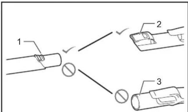
text_image
1 2 3Fig.25
▶ 1. Attachment with lock function 2. Suction inlet with lock function 3. Suction inlet without lock function
Adjusting lengths of slide-type extension wand
Optional accessory
A slide-type extension wand can be combined for shorter and longer lengths. It allows to clean hard-to-reach areas and comfortable positioning options.
Pull in and out the slide pipe to change wand lengths while pressing and holding the slide button.
Release the slide button to lock the slide pipe in your desired position.
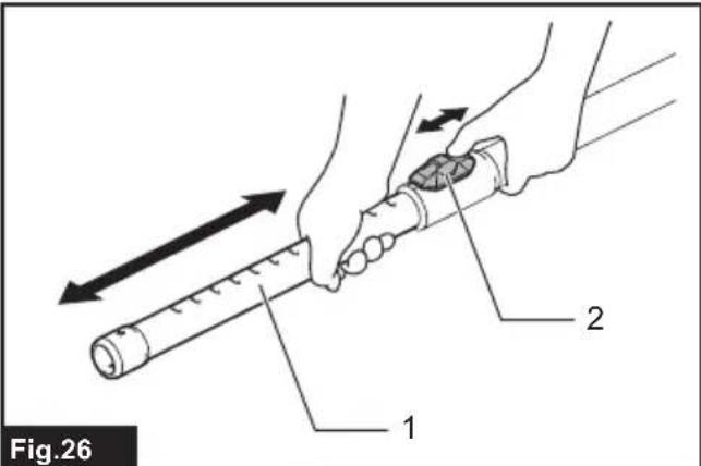
text_image
Fig.26 1 2▶ 1. Slide pipe 2. Slide button
WIRELESS ACTIVATION FUNCTION
What you can do with the wireless activation function
The wireless activation function enables clean and comfortable operation. By connecting a supported tool to the cleaner, you can run the cleaner automatically along with the switch operation of the tool.

natural_image
Diagram of a vacuum cleaner emitting sound waves from a device, labeled Fig.27 (no text or symbols on the diagram itself)NOTICE: Be sure to refer to the instruction manual of the tool when using the cleaner with wireless activation function.
NOTICE: Do not disassemble or tamper with the wireless unit.
NOTICE: To prevent dust coming into the slot of the wireless unit, always close the lid securely during operation and storage.
NOTICE: Do not remove the wireless unit while the power is being supplied. Doing so may cause a malfunction of the wireless unit.
NOTICE: Do not press the wireless activation button too hard and/or press the button with an object with a sharp edge.
NOTE: Wireless activation needs Makita tools equipped with the wireless unit.
NOTE: Prior to the initial use of the wireless activation function with each tool, the tool registration is required. Once the registration is finished with the tool, the re-registration is not required unless it is cancelled.
NOTE: Before registration, be sure that the wireless unit is properly inserted.
NOTE: One wireless unit can register up to 10 links with other wireless units. If more than 10 other wireless units are registered to one wireless unit, the one registered earliest will be cancelled automatically.
NOTE: The position of the wireless activation button varies depending on the tool.
NOTE: The cleaner also starts by pressing the power button when the stand-by switch is set to "AUTO". However the power button will not actuate when the wireless activation function is used.
Installing the wireless unit
⚠️CAUTION: Place the cleaner on a flat and stable surface when installing the wireless unit.
NOTICE: Clean the dust and dirt on the cleaner before installing the wireless unit. Dust or dirt may cause malfunction if it comes into the slot of the wireless unit.
NOTICE: To prevent the malfunction caused by static, touch a static discharging material, such as a metallic part, before picking up the wireless unit.
NOTICE: When installing the wireless unit, always be sure that the wireless unit is inserted in the correct direction and the lid is completely closed.
- Open the lid on the cleaner as shown in the figure.
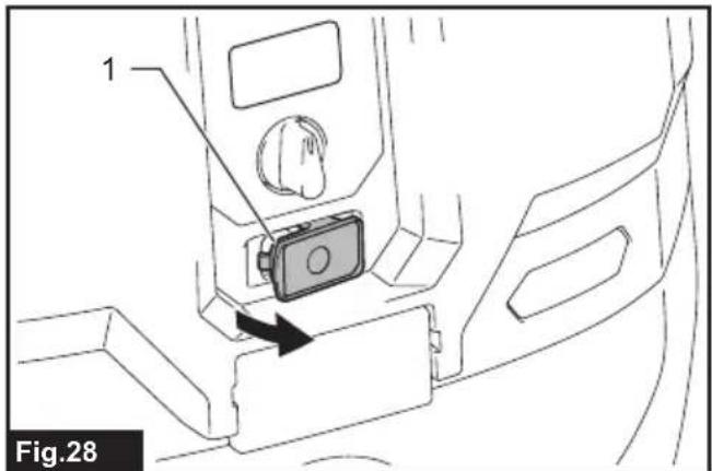
text_image
1 Fig.28-
Lid
-
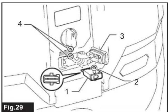
Insert the wireless unit to the slot and then close the lid. When inserting the wireless unit, align the projections with the recessed portions on the slot.
text_image
4 3 2 1 Fig.29▶ 1. Wireless unit 2. Projection 3. Lid 4. Recessed portion
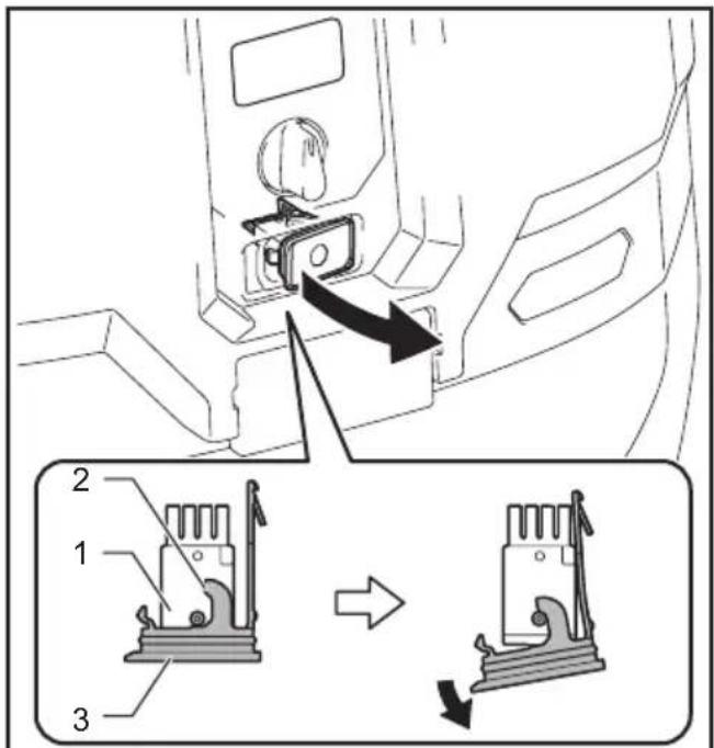
When removing the wireless unit, open the lid slowly. The hooks on the back of the lid will lift the wireless unit as you pull up the lid.
text_image
Diagram showing a car interior with labeled parts and directional arrows indicating movement or change.Fig.30
▶ 1. Wireless unit 2. Hook 3. Lid
After removing the wireless unit, keep it in the supplied case or a static-free container.
NOTICE: Always use the hooks on the back of the lid when removing the wireless unit. If the hooks do not catch the wireless unit, close the lid completely and open it slowly again.
Tool registration for the cleaner
NOTE: A Makita tool supporting the wireless activation function is required for the tool registration.
NOTE: Finish installing the wireless unit to the tool before starting the tool registration.
NOTE: During the tool registration, do not pull the switch trigger on the tool or turn on the power switch on the cleaner.
NOTE: Refer to the instruction manual of the tool, too.
If you wish to activate the cleaner along with the switch operation of the tool, finish the tool registration beforehand.
- Install the wireless units to the cleaner and the tool, respectively.
- Install the batteries to the cleaner and the tool.
- Set the stand-by switch on the cleaner to "AUTO".

text_image
AUTO 1 Fig.31▶ 1. Stand-by switch
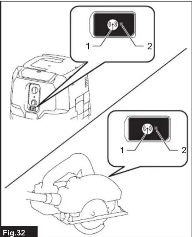
- Press the wireless activation button on the cleaner for 3 seconds until the wireless activation lamp blinks in green. And then press the wireless activation button on the tool in the same way.
text_image
1 2 1 2 Fig.32▶ 1. Wireless activation button 2. Wireless activation lamp
If the cleaner and the tool are linked successfully, the wireless activation lamps will light up in green for 2 seconds and start blinking in blue.
NOTE: The wireless activation lamps finish blinking in green after 20 seconds elapsed. Press the wireless activation button on the tool while the wireless activation lamp on the cleaner is blinking. If the wireless activation lamp does not blink in green, push the wireless activation button briefly and hold it down again.
NOTE: When performing two or more tool registration for the cleaner, finish the tool registration one by one.
Starting the wireless activation function
NOTE: Finish the tool registration for the cleaner for wireless activation.
NOTE: Always place the cleaner so that you can see the status of the wireless activation lamp.
NOTE: Refer to the instruction manual of the tool, too.
After registering a tool to the cleaner, the cleaner will automatically runs along with the switch operation of the tool.
- Install the wireless units to the cleaner and the tool, respectively.
-
Install the batteries to the cleaner and the tool.
-
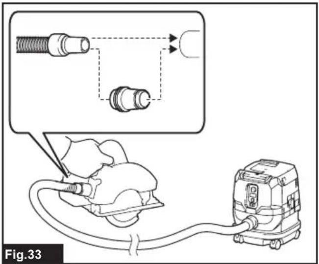
Connect the hose of the cleaner with the tool.
text_image
Fig.33- Set the stand-by switch on the cleaner to "AUTO".

text_image
AUTO 1 Fig.34▶ 1. Stand-by switch
- Push the wireless activation button on the tool briefly. The wireless activation lamp will blink in blue.

text_image
Fig.35▶ 1. Wireless activation button 2. Wireless activation lamp
- Pull the switch trigger of the tool. Check if the cleaner runs while the switch trigger on the tool is being pulled.
CAUTION: Always check if the wireless activation function works before starting a work with the tool.
To stop the wireless activation, push the wireless activation button on the tool, or set the stand-by switch on the cleaner to "I" or "O".
NOTE: The wireless activation lamp on the tool will stop blinking in blue when there is no operation for 2 hours. In this case, set the stand-by switch on the cleaner to "AUTO" and press the wireless activation button on the tool again.
NOTE: The cleaner starts/stops with a delay. There is a time lag when the cleaner detects a switch operation of the tool.
NOTE: The transmission distance of the wireless unit may vary depending on the location and surrounding circumstances.
NOTE: When two or more tools are registered to one cleaner, the cleaner may start running even if you don't pull the switch trigger because other user is using the wireless activation function.
Cancelling tool registration for the cleaner
Perform the following procedure when cancelling the tool registration for the cleaner.
- Install the wireless units to the cleaner and the tool, respectively.
- Install the batteries to the cleaner and the tool.
- Set the stand-by switch on the cleaner to "AUTO".

text_image
AUTO 1 Fig.36▶ 1. Stand-by switch
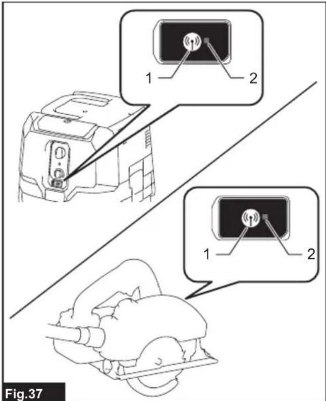
- Press the wireless activation button on the cleaner for 6 seconds. The wireless activation lamp blinks in green and then become red. After that, press the wireless activation button on the tool in the same way.
text_image
1 2 1 2 Fig.37▶ 1. Wireless activation button 2. Wireless activation lamp
If the cancellation is performed successfully, the wireless activation lamps will light up in red for 2 seconds and start blinking in blue.
NOTE: The wireless activation lamps finish blinking in red after 20 seconds elapsed. Press the wireless activation button on the tool while the wireless activation lamp on the cleaner is blinking. If the wireless activation lamp does not blink in red, push the wireless activation button briefly and hold it down again.
Erasing all tool registrations
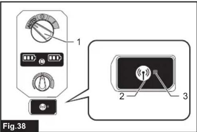
You can erase all tool registrations from the cleaner as follows.
text_image
Fig.38▶ 1. Stand-by switch 2. Wireless activation button 3. Wireless activation lamp
- Install the wireless unit to the cleaner.
- Install the batteries to the cleaner.
- Set the stand-by switch to "AUTO".
- Hold down the wireless activation button for about 6 seconds until the wireless activation lamp blinks in red (about twice per one second).
- When the wireless activation lamp starts blinking in red, release your finger from the wireless activation button. Thereafter, hold down the wireless activation button again for about 6 seconds.
- When the wireless activation lamp starts blinking fast (about 5 times per one second) in red, release your finger from the wireless activation button. When the wireless activation lamp lights up in red and later lights off, all tool registrations are erased.
NOTE: If the wireless activation lamp does not blink in red, press the wireless activation button briefly and try again.
Description of the wireless activation lamp status

text_image
Fig.39 1 2▶ 1. Wireless activation button 2. Wireless activation lamp
The wireless activation lamp shows the status of the wireless activation function. Refer to the below table for the meaning of the lamp status.
| Status Wireless activation lamp Description | |||||
| Standby Blue | On | Blinking | Duration (approximate) | ||
| Tool registration | Green | ☐ | 20 seconds Ready for the tool registration. Searching the tool to be registered. | Waiting for the tool registration or the wireless activation function is available.The lamp on the cleaner blinks when the stand-by switch is set in AUTO. The lamp on the tool blinks when the wireless activation button is pushed. The lamp on the tool will automatically turn off when no operation is performed for 2 hours. | |
| ☐ | 2 seconds The tool registration has been finished. The wireless activation lamp will start blinking in blue. | ||||
| Cancelling/erasing tool registration | Red | ☐(slow: 2 times/sec.) | 20 seconds Ready for the cancellation of the tool registration. Searching the tool to be cancelled. | Ready to erase all tool registrations. | |
| ☐(fast: 5 times/sec.) | When the wireless activation button is pressed down. | ||||
| ☐ | 2 seconds The tool registration has been cancelled/erased. The wireless activation lamp will start blinking in blue. | ||||
| Others Red | ☐ | 3 seconds The power is supplied to the wireless unit and the wireless activation function is starting up. | |||
| Off - - The stand-by switch is not set to "AUTO". | |||||
Troubleshooting for wireless activation function
Before asking for repairs, conduct your own inspection first. If you find a problem that is not explained in the manual, do not attempt to dismantle the tool. Instead, ask Makita Authorized Service Centers, always using Makita replacement parts for repairs.
| State of abnormality Probable cause | (malfunction) Remedy | |
| The wireless activation lamp does not light/blink. | The wireless unit is not installed into the cleaner and/or the tool.The wireless unit is improperly installed into the cleaner and/or the tool. | Install the wireless unit correctly. |
| The terminal of the wireless unit and/or the slot is dirty. | Gently wipe off dust and dirt on the terminal of the wireless unit and clean the slot of the cleaner and/or the tool. | |
| The wireless activation button on the tool has not been pushed. | Push the wireless activation button on the tool briefly. | |
| The stand-by switch on the cleaner is not set to "AUTO". | Set the stand-by switch on the cleaner to "AUTO". | |
| No power supply Supply the power to the tool and the cleaner. | ||
| Cannot finish tool registration / cancelling tool registration successfully. | The wireless unit is not installed into the cleaner and/or the tool.The wireless unit is improperly installed into the cleaner and/or the tool. | Install the wireless unit correctly. |
| The terminal of the wireless unit and/or the slot is dirty. | Gently wipe off dust and dirt on the terminal of the wireless unit and clean the slot of the cleaner and/or the tool. | |
| The stand-by switch on the cleaner is not set to "AUTO". | Set the stand-by switch on the cleaner to "AUTO". | |
| No power supply Supply the power to the tool and the cleaner. | ||
| Incorrect operation | Push the wireless activation button briefly and perform the tool registration/cancellation procedures again. | |
| The tool and cleaner are away from each other (out of the transmission range). | Get the tool and the cleaner closer to each other. The maximum transmission distance is approximately 10 m however it may vary according to the circumstances. | |
| Before finishing the tool registration/cancellation;- the switch trigger on the tool is pulled or;- the power button on the cleaner is turned on. | Push the wireless activation button briefly and perform the tool registration/cancellation procedures again. | |
| The tool registration procedures for the tool or the cleaner has not finished. | Perform the tool registration procedures for the tool and the cleaner at the same timing. | |
| Radio disturbance by other appliances which generate high-intensity radio waves. | Keep the tool and the cleaner away from the appliances such as Wi-Fi devices and microwave ovens. | |
| The cleaner does not run along with the switch operation of the tool. | The wireless unit is not installed into the cleaner and/or the tool.The wireless unit is improperly installed into the cleaner and/or the tool. | Install the wireless unit correctly. |
| The terminal of the wireless unit and/or the slot is dirty. | Gently wipe off dust and dirt on the terminal of the wireless unit and clean the slot of the cleaner and/or the tool. | |
| The wireless activation button on the tool has not been pushed. | Push the Wireless activation button briefly and make sure that the wireless activation lamp is blinking in blue. | |
| The stand-by switch on the cleaner is not set to "AUTO". | Set the stand-by switch on the cleaner to "AUTO". | |
| More than 10 tools are registered to the cleaner. | Perform the tool registration again.If more than 10 tools are registered to the cleaner, the tool registered earliest will be cancelled automatically. | |
| The cleaner erased all tool registrations. | Perform the tool registration again. | |
| No power supply Supply the power to the tool and the cleaner. | ||
| The tool and cleaner are away from each other (out of the transmission range). | Get the tool and the cleaner closer to each other. The maximum transmission distance is approximately 10 m however it may vary according to the circumstances. | |
| Radio disturbance by other appliances which generate high-intensity radio waves. | Keep the tool and the cleaner away from the appliances such as Wi-Fi devices and microwave ovens. | |
| The cleaner runs while the tool's switch trigger is not pulled. | Other users are using the wireless activation of the cleaner with their tools. | Turn off the wireless activation button of the other tools or cancel the tool registration of the other tools. |
| Cannot erase all tool registrations in the cleaner. | Pressing the wireless button on the tool. | Press the wireless button on the cleaner for erasing all tool registrations. |
| The stand-by switch on the cleaner is not set to "AUTO". | Set the stand-by switch on the cleaner to "AUTO". | |
| The wireless activation button is not held down correctly. | Hold down the wireless activation button for more than 6 seconds and then release it when the wireless activation lamp blinks in red. Hold down the wireless activation button for more than 6 seconds again until the wireless activation button rapidly blinks in red and then release the button. | |
MAINTENANCE
⚠CAUTION: Always be sure that the appliance is switched off and the battery cartridges are removed before attempting to perform inspection or maintenance.
NOTICE: Never use gasoline, benzine, thinner, alcohol or the like. Discoloration, deformation or cracks may result.
To maintain product SAFETY and RELIABILITY, repairs, any other maintenance or adjustment should be performed by Makita Authorized or Factory Service Centers, always using Makita replacement parts.
Storage of accessories
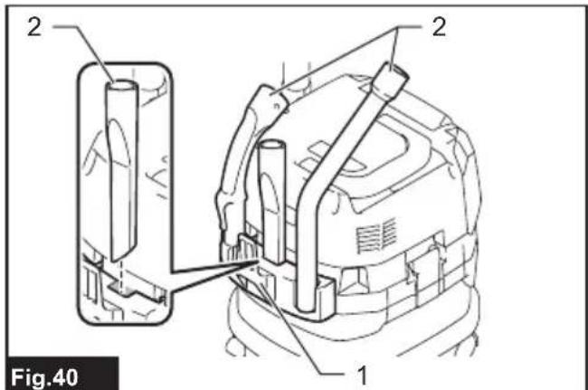
Accessories and attachments not in use, such as nozzles and brushes, can be hooked and stored in the multi hook at the rear of the cleaner.
text_image
2 2 1 Fig.40▶ 1. Multi hook 2. Accessories and attachments not in use
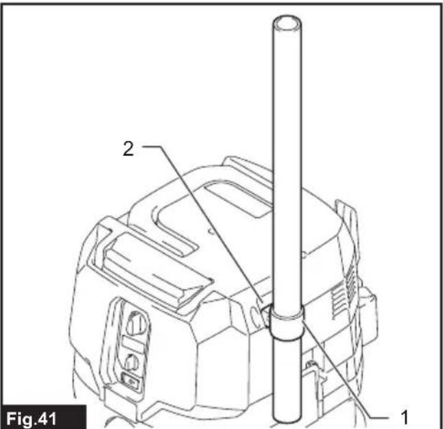
Pipes (with an optional stopper installed) can be placed into the pipe holder when not using the cleaner for a short time.
text_image
Fig.41 1 2▶ 1. Stopper (optional accessory) 2. Pipe holder
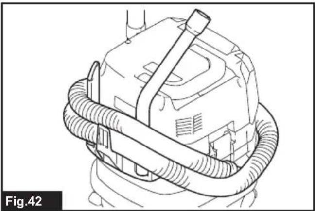
A hose can be wrapped and stored around the housing or handle of the cleaner in large loops. Connect its both ends together to make loops and hook the loops onto the handle raised up. Alternatively, keep its root end installed in the hose inlet and hang the loops on the multi hook with the loose end tied up.
natural_image
Line drawing of a mechanical device with coiled tubing and a handle (no text or symbols)
natural_image
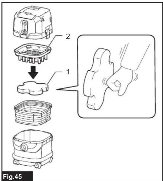
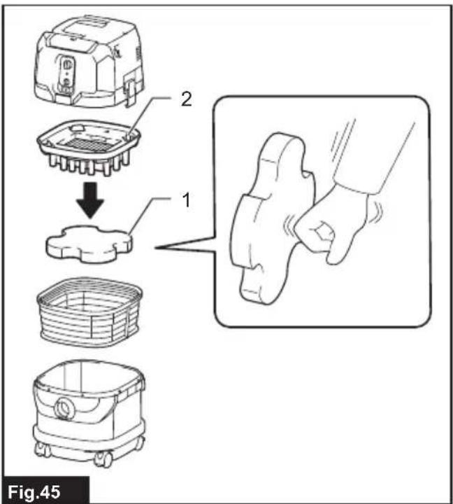
Diagram of a mechanical component with coiled spring-like structures and an inset showing a connector detail (no text or symbols)Cleaning of powder filter (HEPA) and prefilter
Clean out the powder filter, prefilter and damper at regular intervals since clogged filters and damper may result in poor suction performance.
Routinely wipe and shake dust off filters and damper by hand.

natural_image
Technical line drawing of a mechanical device with labeled component '1', no readable text or symbols beyond label and figure marker- Prefilter
text_image
Fig.45- Damper 2. Powder filter (HEPA)
Occasionally wash the powder filter in water, rinse and dry thoroughly in the shade before use. Never wash filters in a washing machine.

natural_image
Line drawing of hands using a tool to clean or adjust a mechanical component (no text or symbols)NOTE: Do not rub or scratch the powder filter, the prefilter and the damper with hard objects such as a brush and a paddle.
NOTE: The filters wear out in course of time. It is recommended to have some spares for them.
OPTIONAL ACCESSORIES
CAUTION: These accessories or attachments are recommended for use with your Makita tool specified in this manual. The use of any other accessories or attachments might present a risk of injury to persons. Only use accessory or attachment for its stated purpose.
If you need any assistance for more details regarding these accessories, ask your local Makita Service Center.
- Hose
- Front cuffs (22, 24, 38)
- Straight pipe
- Extension wand
- Corner nozzle
- Round brush
• Powder filter, HEPA (for dry dust) - Damper
- Prefilter
- Nozzle assembly
- Bent pipe
- Polyethylene bag
- Paper pack
- MAKPAC adapter
- Wireless unit
• Makita genuine battery and charger
NOTE: Some items in the list may be included in the tool package as standard accessories. They may differ from country to country.
MAKITA LIMITED WARRANTY
Please refer to the annexed warranty sheet for the most current warranty terms applicable to this product. If annexed warranty sheet is not available, refer to the warranty details set forth at below website for your respective country.
United States of America: www.makitatools.com
Canada: www.makita.ca
Other countries: www.makita.com
ESPECIFICACIONES
| Modelo: GCV02 GCV04 | ||
| Tipo de filtro estándar Filtro de polvo (para polvo seco) | ||
| Volumen de aire máximo(con BL4040, manguera de ø38 mm (1-1/2") x 2,5 m (98-1/2")) | 2,7 m^3/min (95,35 cu.ft/min) | |
| Aspiradora (con BL4040, manguera de ø38 mm (1-1/2") x 2,5 m (98-1/2")) | 23 kPa | |
| Capacidad recuperable 8 L (2,1 gal) 15 L (4,0 gal) | ||
| Dimensiones (La x An x Al) 366 mm x 334 mm x 425 mm | (14-3/8" x 13-1/8" x 16-3/4") | 366 mm x 334 mm x 475 mm(14-3/8" x 13-1/8" x 18-3/4") |
| Tensión nominal 36 V - 40 V c.c. máx. | ||
| Peso neto | 8,3 kg - 10,2 kg (18,3 lbs - 22,5 lbs) | 8,6 kg - 10,5 kg (19,0 lbs - 23,1 lbs) |
text_image
Exploded view diagram of a cleaning or cleaning device with numbered parts labeled 1 to 5Fig.1
▶ 1. Cabezal 2. Filtro de polvo (HEPA)
- Amortiguador 4. Prefiltro 5. Tanque
text_image
Fig.2 1 2text_image
2 1 Fig.3text_image
1 2 Fig.4text_image
1 2 1 Fig.6natural_image
Diagram of a car back panel with two battery cells and upward arrows indicating charging or discharging (no text or symbols)text_image
2 1 3 Fig.8text_image
Fig.9 1 2 3 4natural_image
Line drawing of a person seated in a vehicle-like device, viewed from the side (no text or symbols)MONTAJE
text_image
Technical diagram showing exploded views of a car interior with labeled components and partsFig.11
text_image
Technical diagram of a robotic device with numbered components and an inset view showing a circular component being turned into a door.Fig.12
text_image
1 2 3 Fig.13natural_image
Technical line drawing of a robotic device with labeled components (no text or symbols beyond labels)- Prefiltro
text_image
1 2 Fig.15natural_image
Technical line drawing of a mechanical device with hoses and connectors, no visible text or symbolstext_image
1 2 Fig.17text_image
1 2 3 Fig.18text_image
3 1 2 Fig.19text_image
Fig.20 1 2- E
text_image
Fig.21 1 2text_image
Technical diagram showing a tool being inserted into a device, with labeled parts and directional arrows indicating process flow.Fig.24
text_image
Fig.26 1 2natural_image
Diagram of a hair dryer connected to a vacuum cleaner, showing airflow and vibration (no text or symbols)text_image
Diagram showing a mechanical assembly with labeled parts and directional arrows indicating movement or transformation.Fig.30
text_image
Diagram of a device control panel with labeled parts and an inset showing a terminal socket with signal indicators.Fig.38
text_image
Fig.39 1 2text_image
Fig.40 1 2 2text_image
Fig.41 1 2natural_image
Line drawing of a mechanical device with coiled tubing and a handle (no text or symbols)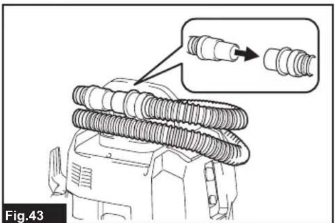
natural_image
Diagram of a mechanical component with coiled spring-like structures and an inset showing a detailed detail (no text or symbols)natural_image
Line drawing of a mechanical device with labeled component '1' (no text or symbols beyond label)- Prefiltro
text_image
Fig.45- Amortiguador 2. Filtro de polvo (HEPA)
natural_image
Line drawing of hands using a tool to lift or spread material inside a mechanical component (no text or symbols)Some dust created by power sanding, sawing, grinding, drilling, and other construction activities contains chemicals known to the State of California to cause cancer, birth defects or other reproductive harm. Some examples of these chemicals are:
- lead from lead-based paints,
• crystalline silica from bricks and cement and other masonry products, and
• arsenic and chromium from chemically-treated lumber.
Your risk from these exposures varies, depending on how often you do this type of work. To reduce your exposure to these chemicals: work in a well ventilated area, and work with approved safety equipment, such as those dust masks that are specially designed to filter out microscopic particles.