H500-GW - Tablet wall mount WindFall - Free user manual and instructions
Find the device manual for free H500-GW WindFall in PDF.

User questions about H500-GW WindFall
0 question about this device. Answer the ones you know or ask your own.
Ask a new question about this device
Download the instructions for your Tablet wall mount in PDF format for free! Find your manual H500-GW - WindFall and take your electronic device back in hand. On this page are published all the documents necessary for the use of your device. H500-GW by WindFall.
USER MANUAL H500-GW WindFall
Assembly & Installation

natural_image
Simple line drawing of a rectangular frame with a circular hole and two small dots, no text or symbols present.Compatible with:
iPad mini 1
iPad mini 2
iPad mini 3
iPad mini 4
Limited Warranty
Heckler Design warrants your product to be free from defect in material and workmanship for a period of two years from the original date of purchase. Electronic components are warranted to be free from defect for a period of one year from the original date of purchase. If you discover a defect, please contact service@hecklerdesign.com. Heckler Design will repair, at our discretion, using new or refurbished components. If repair is not possible, Heckler Design will replace the item.
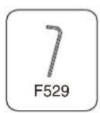
1x

M3 Hex Key F529
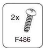
2x

Thread-Forming Mounting Screw F486
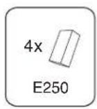
4x
Foam for iPad Fit Adapter Clip E250

Keep your special assembly tool in a safe place. To purchase a replacement, please contact service@hecklerdesign.com.

natural_image
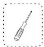
Line drawing of a screwdriver and a circular component (no text or symbols)Phillips Head Screwdriver

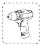
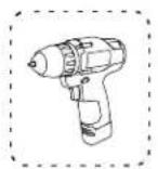
natural_image
Line drawing of a handheld electric drill (no text or symbols)Drill

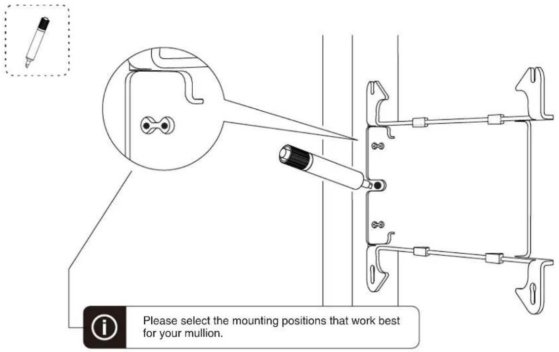
Marker
WindFall Side Mount for iPad mini
Installation Instructions and Template
text_image
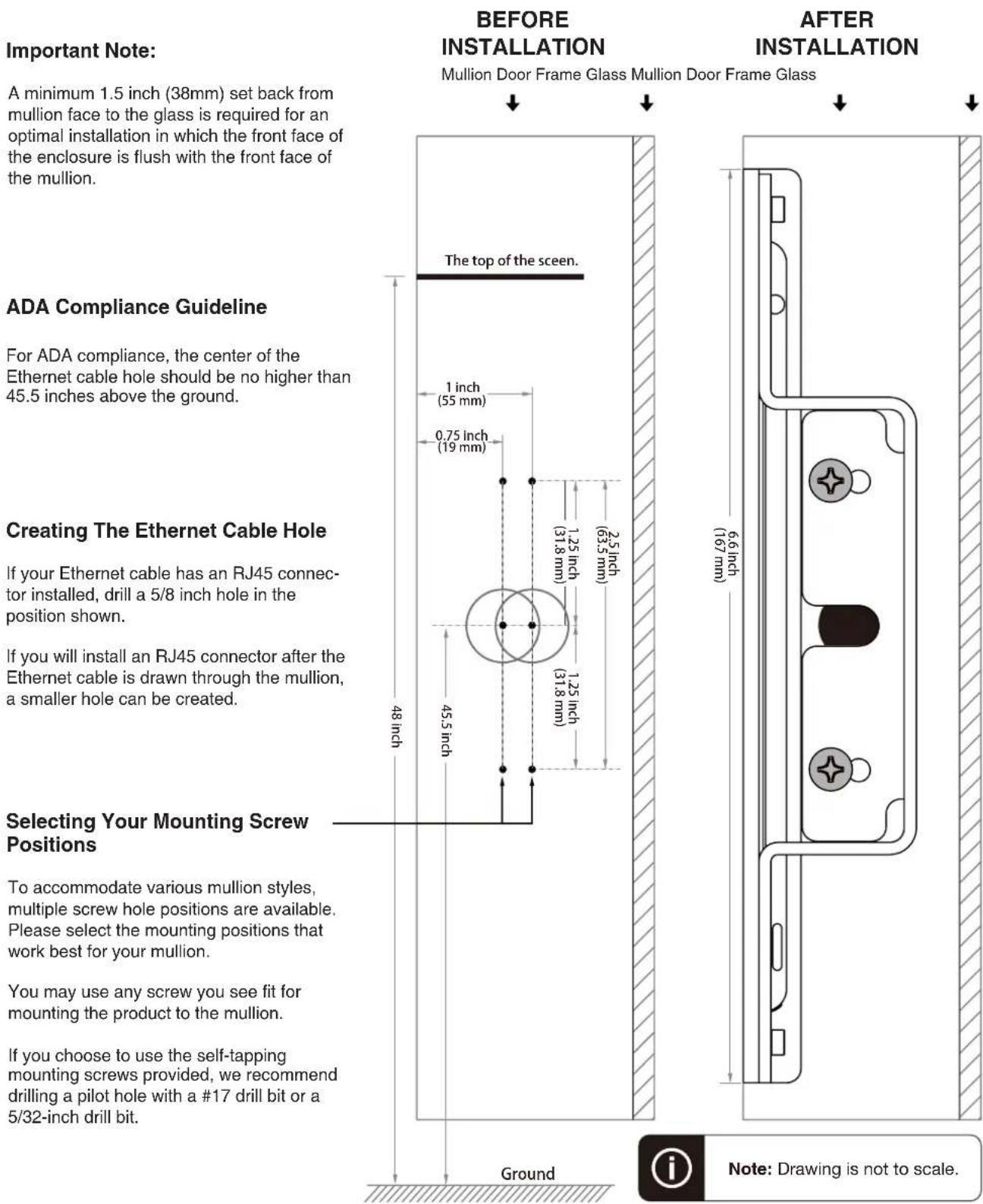
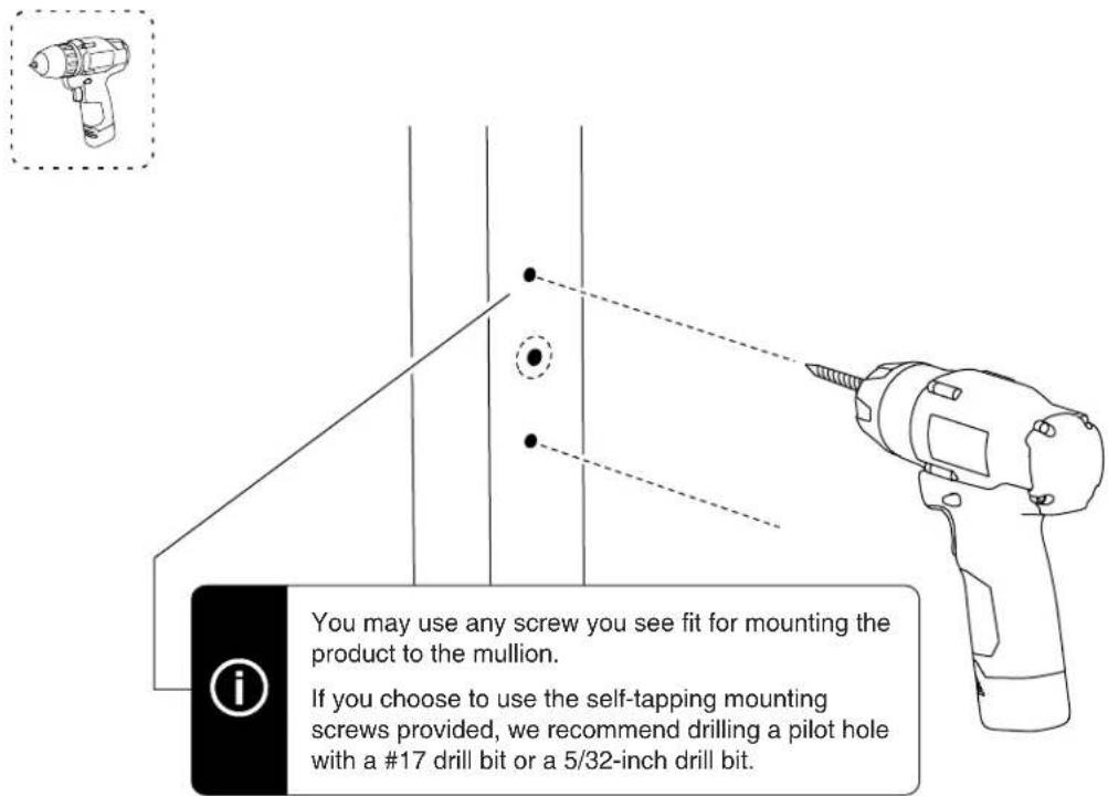
Important Note: A minimum 1.5 inch (38mm) set back from mullion face to the glass is required for an optimal installation in which the front face of the enclosure is flush with the front face of the mullion. BEFORE INSTALLATION Mullion Door Frame Glass Mullion Door Frame Glass ↓ ↓ ADA Compliance Guideline For ADA compliance, the center of the Ethernet cable hole should be no higher than 45.5 inches above the ground. Creating The Ethernet Cable Hole If your Ethernet cable has an RJ45 connector installed, drill a 5/8 inch hole in the position shown. If you will install an RJ45 connector after the Ethernet cable is drawn through the mullion, a smaller hole can be created. Selecting Your Mounting Screw Positions To accommodate various mullion styles, multiple screw hole positions are available. Please select the mounting positions that work best for your mullion. You may use any screw you see fit for mounting the product to the mullion. If you choose to use the self-tapping mounting screws provided, we recommend drilling a pilot hole with a #17 drill bit or a 5/32-inch drill bit. Ground 6.6 inch (167 mm) After INSTALLATION The top of the screen. 1 inch (55 mm) 0.75 inch (19 mm) 1.25 inch (31.8 mm) 2.5 inch (63.5 mm) 48 inch 45.5 inch Ground Note: Drawing is not to scale.1 Disassemble Side Mount
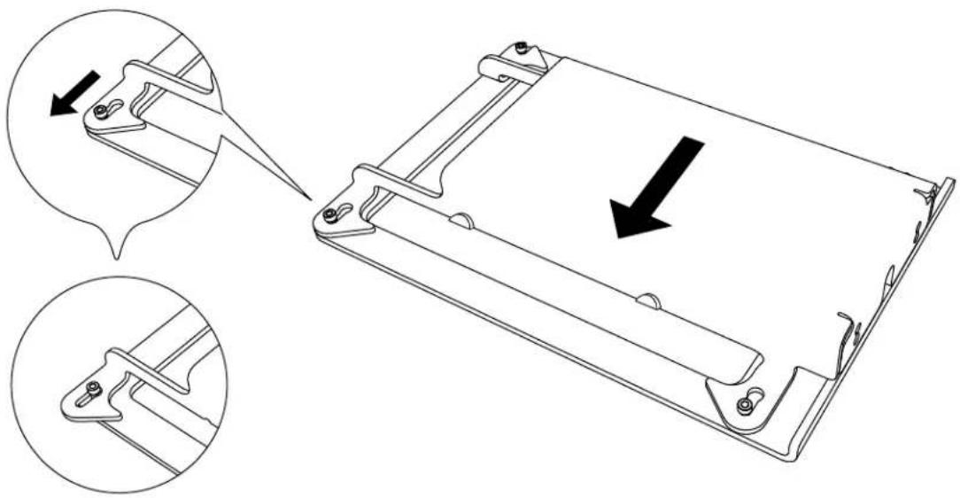
natural_image
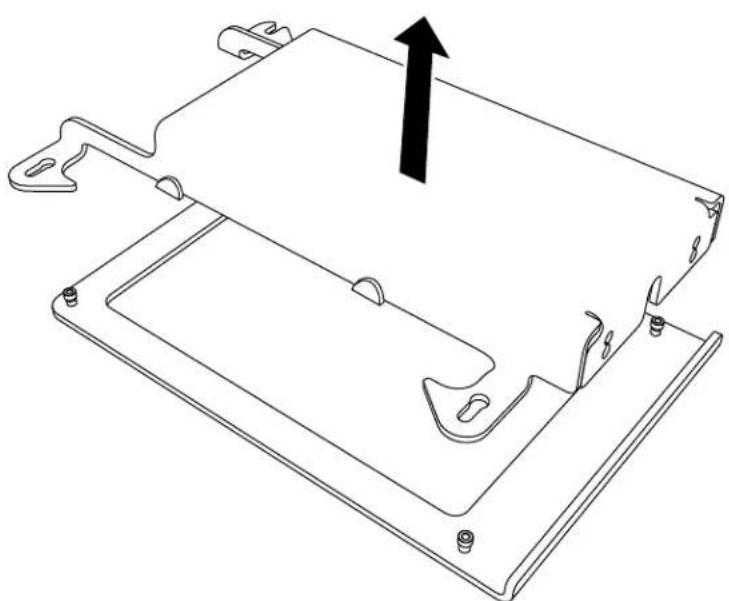
Technical line drawing of a mechanical component with two views showing internal structure and a downward arrow indicating motion (no text or symbols present)2 Remove Mounting Bracket From Front Bezel
natural_image
Technical line drawing of a mechanical component with mounting holes and a central bracket (no text or symbols)Mark Hole Positions3
text_image
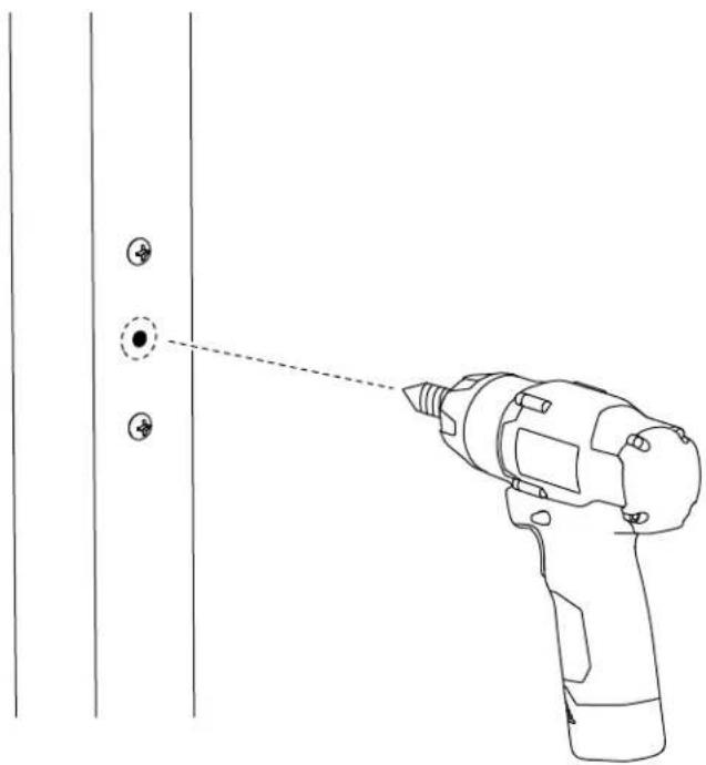
Please select the mounting positions that work best for your mullion.4 Drill Mounting Holes
text_image
You may use any screw you see fit for mounting the product to the mullion. If you choose to use the self-tapping mounting screws provided, we recommend drilling a pilot hole with a #17 drill bit or a 5/32-inch drill bit.5 Form Mounting Hole Threads

text_image
The mounting screws provided are thread-forming screws.
Ethernet Cable Hole
If your Ethernet cable has an RJ45 connector installed, drill a 5/8 inch hole in the position shown.
If you will install an RJ45 connector after the Ethernet cable is drawn through the mullion, a smaller hole can be created.
natural_image
Line drawing of a hand-drawn tool projecting onto a door panel with two circular buttons (no text or symbols)6 Remove Mounting Screws

text_image
Diagram showing a drill bit with a compass tool and a circular motion indicator, illustrating the working principle of a drill.7 Faster Mounting Bracket to mullion


text_image
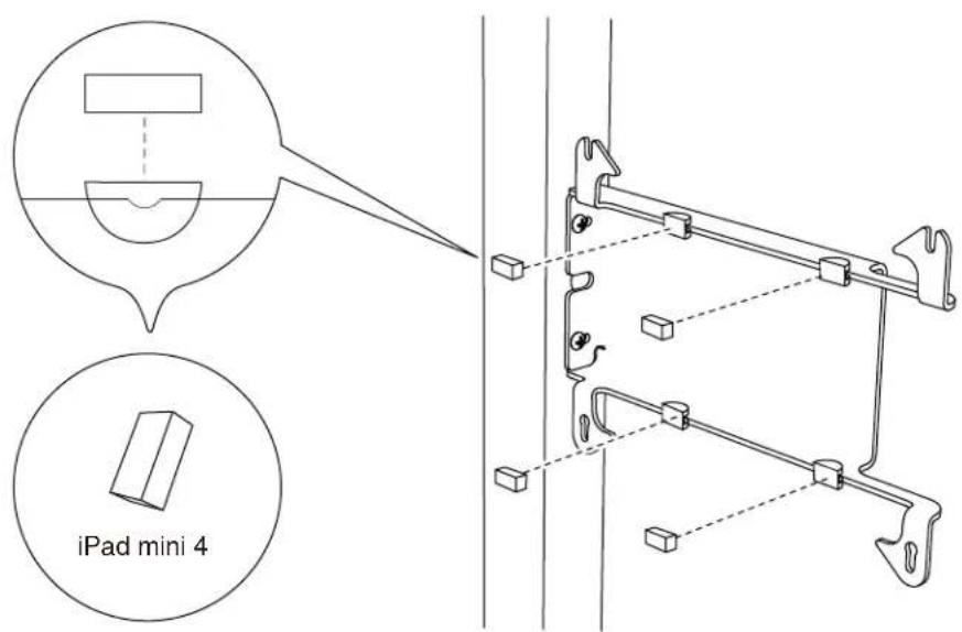
Technical diagram showing a mechanical assembly with labeled parts and a circular arrow indicating rotation or adjustment.Adapter Clips For iPad Mini 4
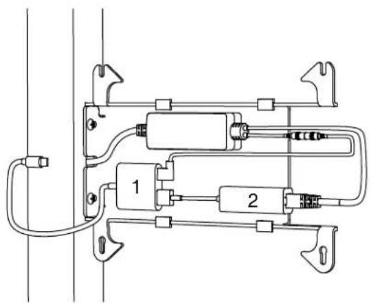
PoE Splitter (Power Only)

natural_image
Pure electrical circuit lines without any symbolsPoE Splitter (With wired data connection)
natural_image
Pure electrical circuit lines without any symbols-
Apple Lighting to USB 3 Camera Adapter
-
Apple USB Ethernet Adapter
Battery Bank
natural_image
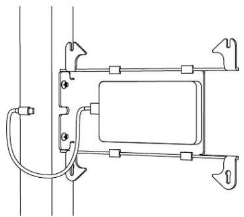
Pure technical line drawing of a mechanical assembly with no text, numbers, or symbols9 Install Tablet
natural_image
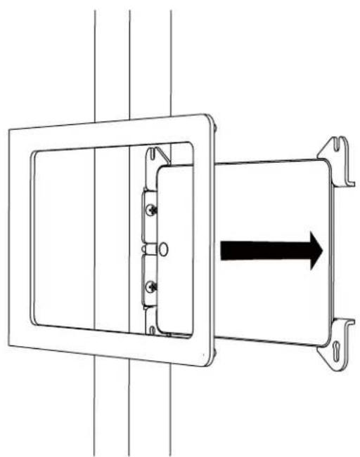
Pure mechanical diagram showing a rectangular component with internal components and a black arrow indicating direction (no text or symbols)10 Install Front Bezel
natural_image
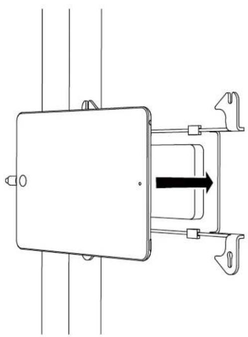
Technical line drawing of a mechanical assembly with a rectangular frame and internal components, showing a black arrow indicating direction (no text or symbols present)11 Slide Front Bezel Onto Mounting Bracket

text_image
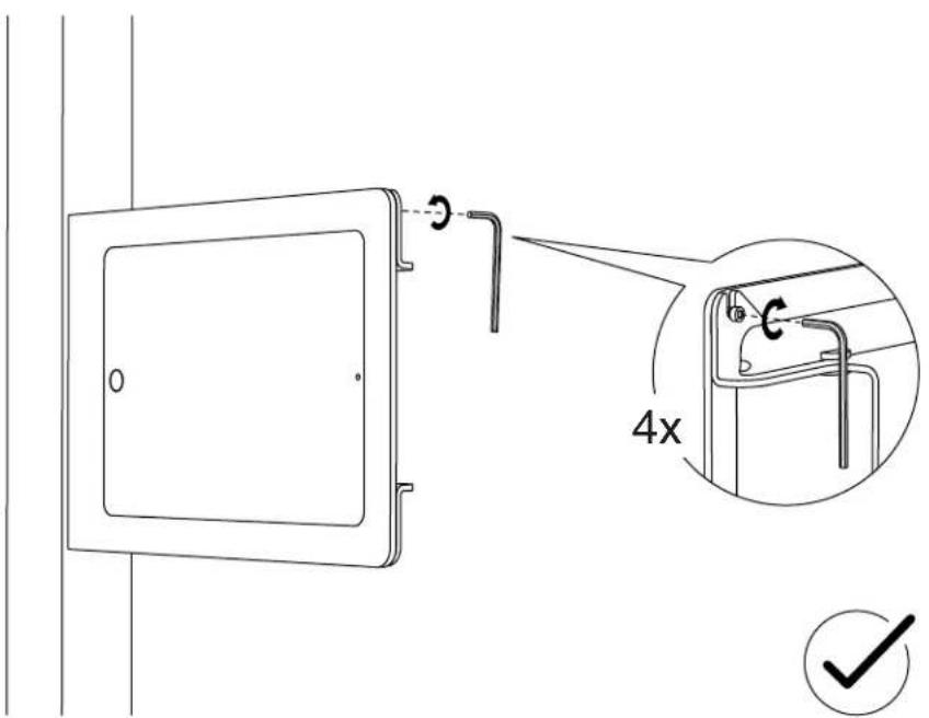
Technical diagram showing a door frame with an arrow indicating direction and two views of the handle mechanism.12 Tighten Assembly Screws