MP-G10-K2 - Sewing machine JUKI - Free user manual and instructions
Find the device manual for free MP-G10-K2 JUKI in PDF.

User questions about MP-G10-K2 JUKI
0 question about this device. Answer the ones you know or ask your own.
Ask a new question about this device
Download the instructions for your Sewing machine in PDF format for free! Find your manual MP-G10-K2 - JUKI and take your electronic device back in hand. On this page are published all the documents necessary for the use of your device. MP-G10-K2 by JUKI.
USER MANUAL MP-G10-K2 JUKI
Pneumatic Type Two Stage Clamp
FOR SAFE USE
Before the installation, operation, and inspection for this product, read the "FOR SAFE USE" and the technical manuals carefully. Also read the other technical manuals, "Sewing Machine Head", "Control Unit" and "Operation Panel" describing some instructions, which are not in this manual, and use the sewing machine properly.
SAFETY INDICATIONS

CAUTION
Indicates that incorrect handling may cause hazardous conditions, resulting in medium or slight personal injury or physical damage. Note that CAUTION level may lead to a serious consequence according to the circumstances. Always follow the instructions of both levels because they are important to personal safety.
CAUTION INDICATIONS
| No. | Caution indication | Description |
| 1 |  | Precaution for sewing machine operation:Indicates that removing the safety and operating the sewing machine for some other purposes with power-on are prohibited.Please do not operate the sewing machine without protective equipment such as a needle guard, an eye guard, a belt cover or the others.Please turn off the power switch when threading, changing a needle and a bobbin, cleaning, and lubricating. |
| 2 |  | Caution for fingers injury:Indicates a possibility of fingers (hands) injury in a certain condition. |
| 3 |  | Caution for squeezing fingers:Indicates a possibility of squeezing fingers in a certain condition. |
1. Features
The pneumatic type (left/right alternating) two-stage clamp separates the pressing operation into the left and right sides. As each side can be operated with individual foot switches, this is suitable for stitching two parts together. Usage methods can be changed to suit the purpose and make setup of the stitching material more efficient. These methods include setting the left/right clamp operation order or canceling the operation order and pressing with the side for which the foot switch is ON.

natural_image
Technical line drawing of a mechanical assembly with mounting flange and housing (no text or symbols)2. Specifications
| Name | : MP-G10-K2 (pneumatic type two stage clamp) | |
| Applicable model: | : PLK-G1010 | |
| Sewing area | : 100 (X) mm X 100 (Y) mm (same as PLK-1010) | |
| Clamp UP position | : 30 mm | |
| Pressing operation | : Use foot switch (2-pedal) normally provided with the industrial sewing machine and expansion foot switch (1-pedal) | |
| Drive source air pressure | Primary side | : 0.5 MPa ( 5 kg/cm^2 ) or more |
| Secondary side: | : 0.4 MPa ( 4 kg/cm^2 ) | |

CAUTION
Trouble such as operation errors could occur if the secondary pressure is set too high. Use within the range of 0.4 MPa (4 kg/cm ^2 ).
3. Configuration
★ The Fig. numbers in the drawing correspond to the part numbers given in the following explanations.
3.1 Clamp mechanism
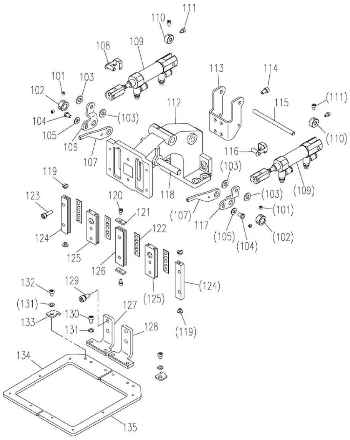
text_image
Exploded view diagram of a mechanical assembly with numbered parts for identification3.1 Clamp mechanism (Parts list)
3.2 Pneumatic pressure control unit
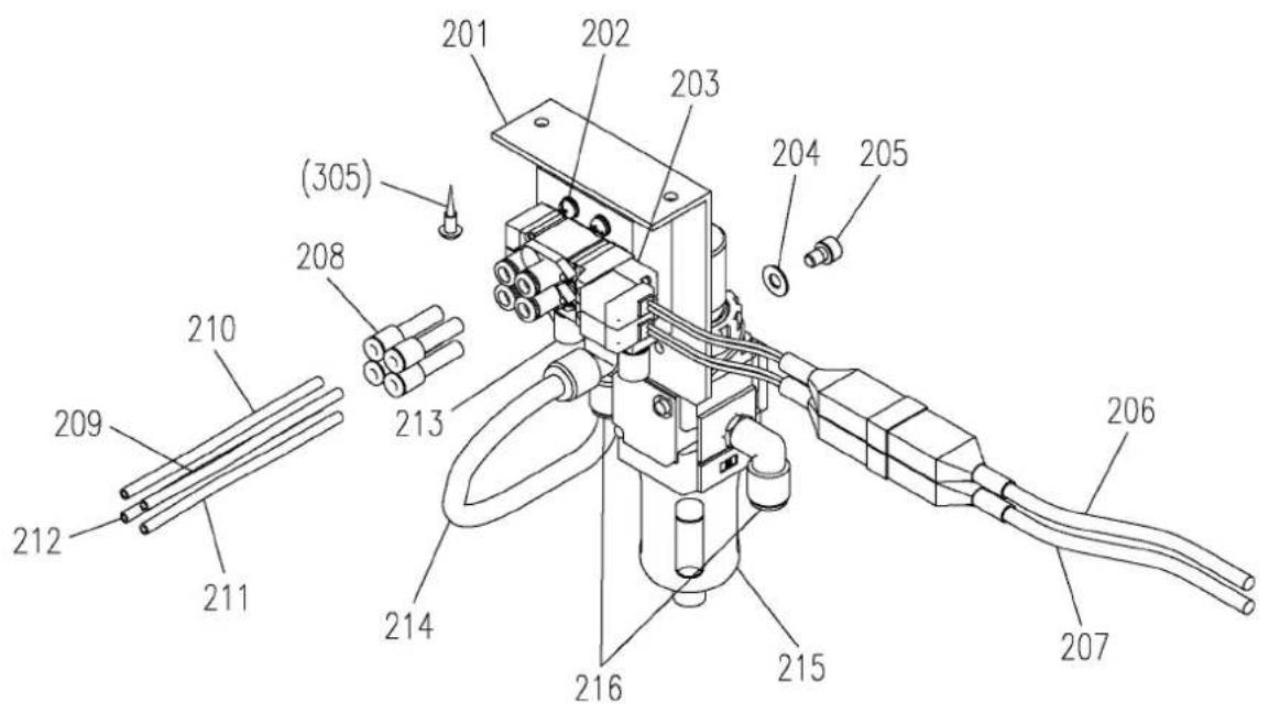
text_image
Technical diagram of a mechanical device with numbered components and labeled parts3.3 Accessories
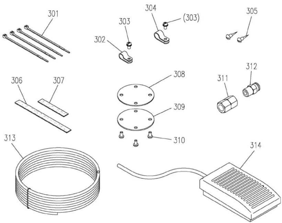
text_image
Technical diagram showing exploded view of mechanical components with numbered parts and a coiled wire.3.2 Pneumatic pressure control unit (Parts list)
3.3 Accessories (Parts list)
Always make sure that the power is OFF before starting setting work.
4.1 Installing the clamp drive mechanism
(1) Remove the four screws on the Y axis movement race side fixing the clamp base (Fig.No.112) and the two screws on the axis support side, and remove the magnetic clamp mechanism mounted as a standard on the sewing machine.
(2) Using the screws removed above, install this pneumatic clamp mechanism following the above step in reverse. Make sure that the clamp is not inclined at this time.
(3) If there is no need to reinstall the magnetic clamp mounted as a standard on the sewing machine after changing to the pneumatic type clamp, it is recommended to remove the drive mechanism parts in the sewing machine head.
To remove these parts, refer to the part catalog P-341 for the PLK-G1010 sewing machine unit, and remove the parts including Fig.No.H130 pin E, and Fig.No.H120 presser plate shown in the catalog. Use the parts Fig.No.308, 309, and 310 enclosed with this attachment as a cover.
4.2 Installing the pneumatic pressure control related parts
(1) The regulator and solenoid valve assembly configured of Fig.No.201, etc., are fixed to the bottom of the sewing machine table with the enclosed Fig.No.305 wood screws (two screws).
(2) Align the piping symbols of the Fig.No.209, 210, 211 and 212 air tubes ( 4) with ports A to D on the pneumatic two stage clamp's Fig.No.109 air cylinder, and insert the tubes.
(3) Pass the air tubes through the notched section on the side of the sewing machine unit's motor cover, and lead the tubes to the bottom of the table from the square hole on the table.
(4) Align the air tubes ( 6) led out above with the ports A to D of the solenoid valve installed in step (1), and insert the tubes.
(5) Bind the air tubes appropriately with the enclosed Fig.No.301 Cable ties.
4.3 Connecting the switches and cables
(1) Remove the cover for the connector panel on the back of the sewing machine.
(2) Disconnect the cable connected to CON13 (FU) on the solenoid PCB. This cable is not used after this attachment is mounted. Fix it where it will not obstruct the other electric parts.
(3) Lead out the Fig.No.206 and 207 cables connected to the solenoid valve from the slot on the back of the sewing machine table, pass through the cord bushing on the connector panel, and lead in to the solenoid PCB side.
(4) Insert the Fig.No.206 cable connector to CON13 (FU) on the PCB from where the cable was disconnected above.
(5) Insert the Fig.No.207 cable connector to CON15 (OP1) on the PCB.
(6) Connect the Fig.No.314 foot switch (1-pedal) cable to the connector (12P) on the head of the sewing machine. The green lead wire is the grounding wire. Connect this wire to the sewing machine bed.
(7) This completes the connection of the wiring. Check the connection with the following table, and then securely install the cover removed from the connector panel.
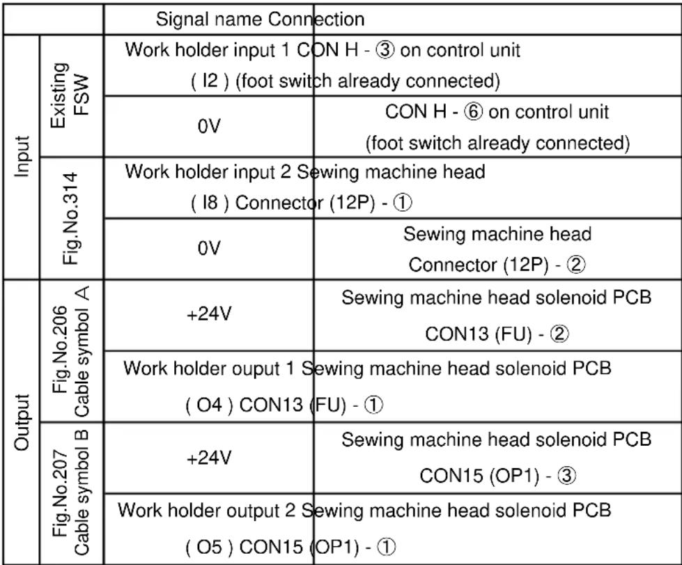 |  |
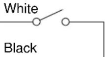 | |
 | |
| Black | |
 | |
| Black |
4.4 Installing the system software

CAUTION
If the sewing machine is operated with the magnetic clamp settings, faults could occur. Always install the system software for the pneumatic type clamp.
(1) Installing the System Software
① While holding down the [F] key on the front panel of the control box, turn the machine power ON. (Keep pushing [F] key until red LED on the front panel is turned on.)
② [Model and language set function] screen is displayed.
③ Press the |c|. Select the English on the language set function screen then, press
the


on the language set function screen then, press
④ Press the . Select the 1010K2 on the model set function screen then, press
the


⑤ Press the ↓ to determine the settings.
⑥ After [INITIALIZES SET VALUE] message is displayed, press the
This completes installing the system software. Turn off the power switch once.
(2) Points changed in setting details
The settings will be changed as shown below when the above system software is installed.
| Mode | Function name | Two Stage clamp | Factory setting | Remarks |
| Clamp | FN | 2 | 1 | Setting for valid number of clamp |
| Input/output setting | I8 | IF2 | NO | Setting for operating work holder input 2 |
| Input/output setting | O4 | 66H | 33 | Set this when changing from the magnetic clamp to the pneumatic clamp. |
| Input/output setting | O5 | 66H | 33 | Set this when changing from the magnetic clamp to the pneumatic clamp. |
4.5 Setting the clamp priority order
As the default, the left/right work clamp is set to operate randomly when the foot switch is turned ON. To use this attachment so that the left clamp is lowered and then the right clamp is lowered, change the settings with the following procedures after installing the system software.
When this method is set, the operation will start with the left clamp, so turn the left clamp foot switch (2-pedal) [black] side ON. If the right clamp foot switch (1-pedal) is turned ON, neither the left nor right clamp will operate.
(1) Press the MENU on the standard screen to open the MENU mode.
(2) Press the Program in the menu icon. The Program Mode [Mode Selection] screen is displayed.
(3) Press the Clamp
(4) The program Mode [Set Selection] is displayed.
(5) Set the clamp priority order. Press the WHY [Priority of clamp mode].
(6) Change the priority order invalid display ☐ on the screen to valid ☐, and the press the ↕.
(7) Press the × on the screen.
(8) Then screen return to the [Mode Selection]. Press the
This completes the setting of the [clamp priority order].
5. Operation
5.1 Confirming operation
(1) Turn the sewing machine power switch ON.
(2) Confirm that the left and right work clamps lower when the foot switch (2-pedal) [Black] side and the expanded foot switch (1-pedal) are turned ON, and rise when the switches are turned ON again.
(3) Lower the left and right work clamps, and press start.
on the operation panel. Return to home will
(4) Next, check that the positional relation of the clamp and needle hole center is at the scale shown in the drawing. If the positions are deviated, refer to the PLK-G1010 Sewing Machine Head version instruction manual and adjust the home.

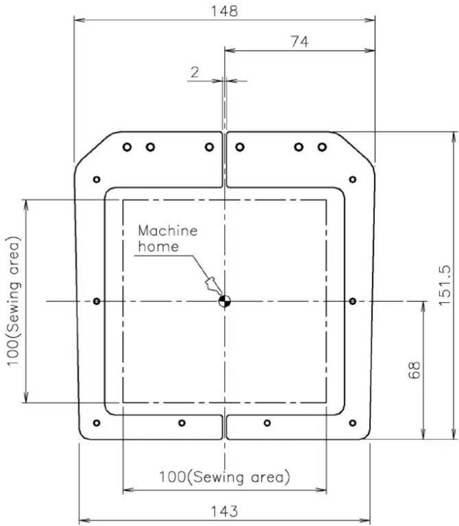
text_image
148 74 2 Machine home 100(Sewing area) 151.5 68 100(Sewing area) 1435.2 Stitching test
(1) Select the stitching pattern. (Refer to the PLK-G1010 Sewing Machine Head version instruction manual.)
(2) Press the [Black] side on the 2-pedal foot switch and the 1-pedal foot switch, and lower the left and right work clamps. Next, press the [Gray] side on the foot switch to rotate the sewing machine and start stitching. (Stitching will not start unless the left and right work clamps are lowered.)
(3) When stitching is completed, the sewing machine will automatically return to home, and the clamps will rise.
MEMO
MEMO