MP-G20-TE - Sewing machine JUKI - Free user manual and instructions
Find the device manual for free MP-G20-TE JUKI in PDF.

User questions about MP-G20-TE JUKI
0 question about this device. Answer the ones you know or ask your own.
Ask a new question about this device
Download the instructions for your Sewing machine in PDF format for free! Find your manual MP-G20-TE - JUKI and take your electronic device back in hand. On this page are published all the documents necessary for the use of your device. MP-G20-TE by JUKI.
USER MANUAL MP-G20-TE JUKI
INDUSTRIAL SEWING MACHINE Attachment
MODEL
MP-G20-TE
TECHNICAL MANUAL
I/O Extension Unit
FOR SAFE USE
Before the installation, operation, and inspection for this product, read the "FOR SAFE USE" and the technical manuals carefully. Also read the other technical manuals, "Sewing Machine Head", "Control Unit" and "Operation Panel" describing some instructions, which are not in this manual, and use the sewing machine properly.
SAFETY INDICATIONS

CAUTION
Indicates that incorrect handling may cause hazardous conditions, resulting in medium or slight personal injury or physical damage. Note that CAUTION level may lead to a serious consequence according to the circumstances. Always follow the instructions of both levels because they are important to personal safety.
CAUTION INDICATIONS
| No. | Caution indication | Description |
| 1 | 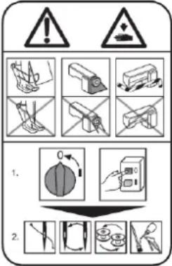 | Precaution for sewing machine operation:Indicates that removing the safety and operating the sewing machine for some other purposes with power-on are prohibited.Please do not operate the sewing machine without protective equipment such as a needle guard, an eye guard, a belt cover or the others.Please turn off the power switch when threading, changing a needle and a bobbin, cleaning, and lubricating. |
| 2 |  | Caution for fingers injury:Indicates a possibility of fingers (hands) injury in a certain condition. |
| 3 |  | Caution for squeezing fingers:Indicates a possibility of squeezing fingers in a certain condition. |
1. Features
This board expands the sum of the I/O ports of the PLK-G series.
12 input and 12 output ports in addition to the number of ports of Standard I/O can be expanded by installing this board.*1 *2
The setting of these expanded ports can be changed from the input/Output setting mode.
*1 It is not necessary to install the latest system software at PLK-G control unit.
*2 These outputs are for air valve only. The solenoid can not be driven.
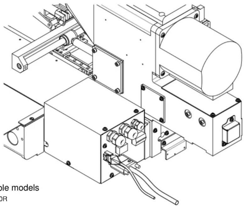
natural_image
Technical line drawing of mechanical components including motors, enclosures, and wiring (no text or symbols)2. Applicable models
PLK-G2010R
PLK-G2516
PLK-G2516R
PLK-G2516-YU
3. Before use
It describes the parts structure and mounting method in this Technical Manual.
Please see the Technical Manual "PLK-G2-TE" is how to set up and handling.
4. Configuration
The Fig. numbers in the drawing correspond to the part numbers given in the following explanations. When ordering service parts, please specify in the Parts No. (M*****).
4.1 I/O Expansion Unit

text_image
Exploded view diagram of an electronic device with numbered components and Chinese labels4.1 I/O Expansion Unit (Parts list)
4.2 Accessories (Parts list)
5. Assembly procedures

CAUTION
★ When installing removal of parts, please go to turn off the power before. In addition, qualified personnel of electrical work, please be performed by wiring work.
5.1 Installing the I/O Expansion Unit
(1) Turn off the power.
(2) Remove the circuit board cover as shown in Figure 1. (This cover is not used after the I/O Expansion Unit attached.)
(3) Disconnect the extension cable for the power supply and signals of the circuit board.
(4) Disconnect the connector mounting plate. (This mounting plate is not used after the I/O Expansion Unit attached.)
(5) Remove the connector "SEN 1", "CON L" and "CON M" from the connector mounting plate as shown in Figure 1.
(6) Attach the connector "CON L" and "CON M" to the Fig.No.102 connector mounting plate.
(7) Attach the connector "CON N" on the I/O Expansion Unit shown in Figure 2 to the Fig.No.102 connector mounting plate.
(8) Attach the Fig.No.102 connector mounting plate to the sewing machine by the screws "M4" provided.
(9) Connect the connector "SEN 2" of the I/O Expansion Unit and the connector "SEN 1".
(10) Connect the connector "CON 2" of the circuit board and the signal line of the I/O Expansion Unit.
(11) Attach the extension board assembly consisting of Fig.No.106 to the Fig.No.102 connector mounting plate by the screws "M4" provided.
(12) Connect the extension cable for the power supply to the connector "CON N". Connect the extension cable for the signals to the circuit board.
(13) Attach the Fig.No.101 cover to the sewing machine by the screw "M4" provided.
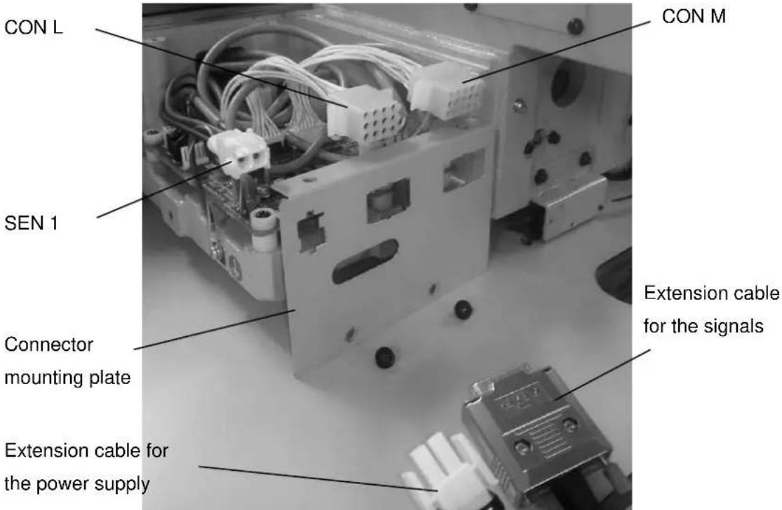
text_image
CON L SEN 1 CON M Connector mounting plate Extension cable for the power supply Extension cable for the signalsFig.1

flowchart
graph TD
    A["PLK-G2-SOL"] -->|CON P| B["Control unit"]
    A -->|SEN1| C["PLK-G2-TE"]
    A -->|SEN2| C
    A -->|CON N| D["Control unit"]
    A -->|CON C| E["Control unit"]
    F["Sewing Machine head"] --> A
    G["CON P"] --> A
    H["CON2"] --> A
    I["CON1"] --> A
    J["CON1"] --> C
    K["CON1"] --> C
Fig.2
5.2 How to set up and attached confirmation

CAUTION
Assembly of this device is completed, please check your work once again.
Because there is a case to unexpected behavior, please away from the sewing machine when the power is turned on and the air pressure.
(1) Please confirm if have finished the installation of the I/O Expansion Unit.
Please see the Technical Manual "PLK-G2-TE" is how to check this.
(2) The connection to the input and output ports, can be done by removing the Fig.No.101 cover.
MEMO
MEMO