MP-G20R-TH - Sewing machine JUKI - Free user manual and instructions
Find the device manual for free MP-G20R-TH JUKI in PDF.

User questions about MP-G20R-TH JUKI
0 question about this device. Answer the ones you know or ask your own.
Ask a new question about this device
Download the instructions for your Sewing machine in PDF format for free! Find your manual MP-G20R-TH - JUKI and take your electronic device back in hand. On this page are published all the documents necessary for the use of your device. MP-G20R-TH by JUKI.
USER MANUAL MP-G20R-TH JUKI
Upper Thread-Holding Device
FOR SAFE USE
Before the installation, operation, and inspection for this product, read the "FOR SAFE USE" and the technical manuals carefully. Also read the other technical manuals, "Sewing Machine Head", "Control Unit" and "Operation Panel" describing some instructions, which are not in this manual, and use the sewing machine properly.
SAFETY INDICATIONS

CAUTION
Indicates that incorrect handling may cause hazardous conditions, resulting in medium or slight personal injury or physical damage. Note that CAUTION level may lead to a serious consequence according to the circumstances. Always follow the instructions of both levels because they are important to personal safety.
CAUTION INDICATIONS
| No. | Caution indication | Description |
| 1 | 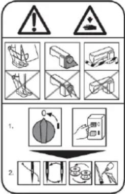 | Precaution for sewing machine operation:Indicates that removing the safety and operating the sewing machine for some other purposes with power-on are prohibited.Please do not operate the sewing machine without protective equipment such as a needle guard, an eye guard, a belt cover or the others.Please turn off the power switch when threading, changing a needle and a bobbin, cleaning, and lubricating. |
| 2 |  | Caution for fingers injury:Indicates a possibility of fingers (hands) injury in a certain condition. |
| 3 |  | Caution for squeezing fingers:Indicates a possibility of squeezing fingers in a certain condition. |
1. Features
Upper Thread-Holding Device will improve the quality of the sewing start point. By gripping the upper thread after thread trimming sewing end, to prevent the thread fall out at the sewing start point.
2. Applicable models
PLK-G2010R
PLK-G2516
PLK-G2516R
PLK-G2516-YU
PLK-G4030 / G4030R
PLK-G6030 / G6030R
PLK-G5050 / G5050R
PLK-G10050 / G10050R

natural_image
Technical line drawing of a sewing machine mechanism (no text or symbols)Fig.1
Mounting example of
the upper thread holding mechanism
3. Specifications
Upper thread holding stroke
Control power supply
Drive source air pressure
Primary side
Secondary side
: 23mm
: DC24V
: 0.5 MPa (5 kgf /cm²) or more
: 0.4 MPa (4 kgf /cm²)

CAUTION
Trouble such as operation errors could occur if the secondary pressure is set too high.
Use within the range of 0.4 MPa (4 kgf/cm ^2 ).
4. Configuration
The Fig. numbers in the drawing correspond to the part numbers given in the following explanations. When ordering service parts, please specify in the Parts No. (M*****).
4.1 Upper thread holding mechanism (Parts list)
4.2 Pneumatic pressure control unit (Parts list)
text_image
An example of a mounting bracket (Not included) 107A 107B 108 101 105 102 103 106 103 104 204 203 201 202 Fig.2Fig.3 Pneumatic pressure control unit
Fig.2
Upper thread holding mechanism
4.3 Accessories (Parts list)
5. Assembly procedures

CAUTION
★ To work in the presence of residual pressure in the pneumatic circuit It is dangerous. Please work after you remove the residual pressure always. The method of removing the residual pressure, and pull up the handle of the pressure regulating filter regulator, can be done by turning counter-clockwise until the pressure gauge shows 0.
★ When installing removal of parts, please go to turn off the power before. In addition, qualified personnel of electrical work, please be performed by wiring work.
5.1 Installing the upper thread holding mechanism
(1) Make a bracket for mounting the upper thread holding mechanism. (Shows an example in Figure 2.)
★ Please consult sewing machine shop for the fabrication of bracket.
The mounting of the upper thread holding mechanism, you can use the mounting holes of the wiper mechanism, to or attached to the face cover. Attach a position that does not interfere with the holding jig to position the sewing material, consider including the sewing pattern and workability.
(2) Remove the wiper mechanism from the machine arm. Is not only part of the wiper drive, please remove the connection wires from the sewing machine.
★ Can not be shared with the wiper mechanism and Upper Thread-Holding Device.
(3) Attach the upper thread holding mechanism to the machine arm. Please adjust the position of the upper thread holding mechanism so that the thread distributor Fig.No.106 scoop a thread between the presser foot and the needle, as shown in Figure 1.
5.2 Installing the pneumatic pressure control related parts and piping
Please connect the pipes so that the state of the air cylinder rod is returned when the power is turned off. If the rod is advanced, please replace the pipe to the joint A and B of the solenoid valve after the removal of the air pressure to stop the air.
(1) The 0 to the air pressure by turning the pressure adjustment knob of the filter regulator, and remove any residual pressure.
(2) Remove the packing and C blanking plate D from the solenoid valve as shown in Figure 4, and install a solenoid valve attached. At this time, attach the packing included with this in order to prevent air leakage.
(3) Insert to match the symbols A and B of the air tubes "Fig.No.203 and 204" into the ports "Fig.No.107A and 107B" of the upper thread holding mechanism.
(4) Insert to match the symbols A and B of the air tubes into the ports "A and B" of the solenoid valve.
(5) Bind the air tubes appropriately with the enclosed Fig.No.301 Cable ties.

text_image
Technical diagram showing assembly steps of a mechanical component with labeled parts A, B, and C, including a close-up view of a screw.Fig.4
5.3 How to setup and cable connection
(1) Remove the circuit board cover on the back of the sewing machine.
(2) Disconnect the cable connector of the wiper connected to CON11 on the circuit board.
(3) Connect the connector of Fig.No.202 cable assy to CON11 on the circuit board.
(4) Connect the connector of sensor of the air cylinder to CON9 on the circuit board.
(5) Install the circuit board cover removed.
Output (CON 11)
| Printed character | Signal | Pin No. | |
| W | O2 | Upper thread holding | 1 |
| - | - | 2 | |
| +24V | DC24V | 3 | |
Input (CON 9)
| Printed character | Signal | Pin No. | |
| FSW | +12V | DC12V | 1 |
| I7 | S6(Thread trimming protection signal) | 2 | |
| GND | Ground | 3 | |
5.4 How to setup and cable connection
(1) Press the MENU on the standard screen to open the MENU mode.
(2) Press the in the menu icon. The Input/Output setting mode screen is displayed.
(3) Press the on the Input/Output setting mode, and enter a password.
Please ask the dealer about a password.
Input Customize Setting screen, press the button on the lower side of the physical input RAM "17".( Input signal is displayed on the button, the default is "NO".) The Function Section screen will open.
(4) Select input signal "S6" by pressing the button | ↑ | ↓ | .
(5) Press the | SETTING| and display the screen of the Detailed Setting.
(6) Change the "reversed" from the "normal" a logical setting by pressing the button USUAL ,
press the button

(7) Press the × .
(8) Press the [TOP] and return to standard screen.
The settings will be changed to the table shown next by the above operation.
For details, refer to the clause [14] Input/output setting mode of the technical manual "Operation Panel".
| Default value | After changing the setting | |
| Input signal | NO | S6 |
| Signal name | -- | Thread trimming protection signal |
| Logical setting | normal | reversed |
6. Operation

CAUTION
Assembly of this device is completed, please check your work once again.
Because there is a case to unexpected behavior, please away from the sewing machine when the power is turned on and the air pressure.
(1) Pull up on the handle of the filter regulator, adjust to 0.4MPa(4kgf/cm²) air pressure by turning in a clockwise direction.
(2) Upper Thread-Holding Device will work in the program of the wiper.
For the timing adjustment of the operation, refer to the clause of the technical manual "Control Unit".
7. Upper thread holding mechanism outline drawing

text_image
2-M4 Internal thread 5 8 16 20 32.5 147.7 23str 62.9 8.8 3.2 12 11 19MEMO
MEMO