MP-J25-AD - Sewing machine JUKI - Free user manual and instructions
Find the device manual for free MP-J25-AD JUKI in PDF.

User questions about MP-J25-AD JUKI
0 question about this device. Answer the ones you know or ask your own.
Ask a new question about this device
Download the instructions for your Sewing machine in PDF format for free! Find your manual MP-J25-AD - JUKI and take your electronic device back in hand. On this page are published all the documents necessary for the use of your device. MP-J25-AD by JUKI.
USER MANUAL MP-J25-AD JUKI
INDUSTRIAL SEWING MACHINE
Attachment
MODEL
MP-J25-AD
TECHNICAL MANUAL
Abnormal Stitch Detector
FOR SAFE USE
Before the installation, operation, and inspection for this product, read the "FOR SAFE USE" and the technical manuals carefully. Also read the other technical manuals, "Sewing Machine Head", "Control Unit" and "Operation Panel" describing some instructions, which are not in this manual, and use the sewing machine properly.
SAFETY INDICATIONS

CAUTION
Indicates that incorrect handling may cause hazardous conditions, resulting in medium or slight personal injury or physical damage. Note that CAUTION level may lead to a serious consequence according to the circumstances. Always follow the instructions of both levels because they are important to personal safety.
CAUTION INDICATIONS
| No. | Caution indication | Description |
| 1 | 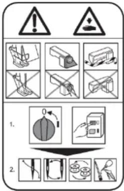 | Precaution for sewing machine operation:Indicates that removing the safety and operating the sewing machine for some other purposes with power-on are prohibited.Please do not operate the sewing machine without protective equipment such as a needle guard, an eye guard, a belt cover or the others.Please turn off the power switch when threading, changing a needle and a bobbin, cleaning, and lubricating. |
| 2 | 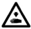 | Caution for fingers injury:Indicates a possibility of fingers (hands) injury in a certain condition |
| 3 |  | Caution for squeezing fingers:Indicates a possibility of squeezing fingers in a certain condition. |
Introduction
It is not possible for this device to detect all abnormal stitch. Please use this device after reading this technical manual a lot and being sure to adjust depend on threads and sewing materials.
Note If you use this device without adjusting, there are risk that it causes the yet to be detected and misdetection.
1. Configuration
The Fig. numbers in the drawing correspond to the part numbers given in the following explanations. When ordering service parts, please specify in the Parts No. (M*****).
1-1. Abnormal stitch detector parts, Fiber amp parts
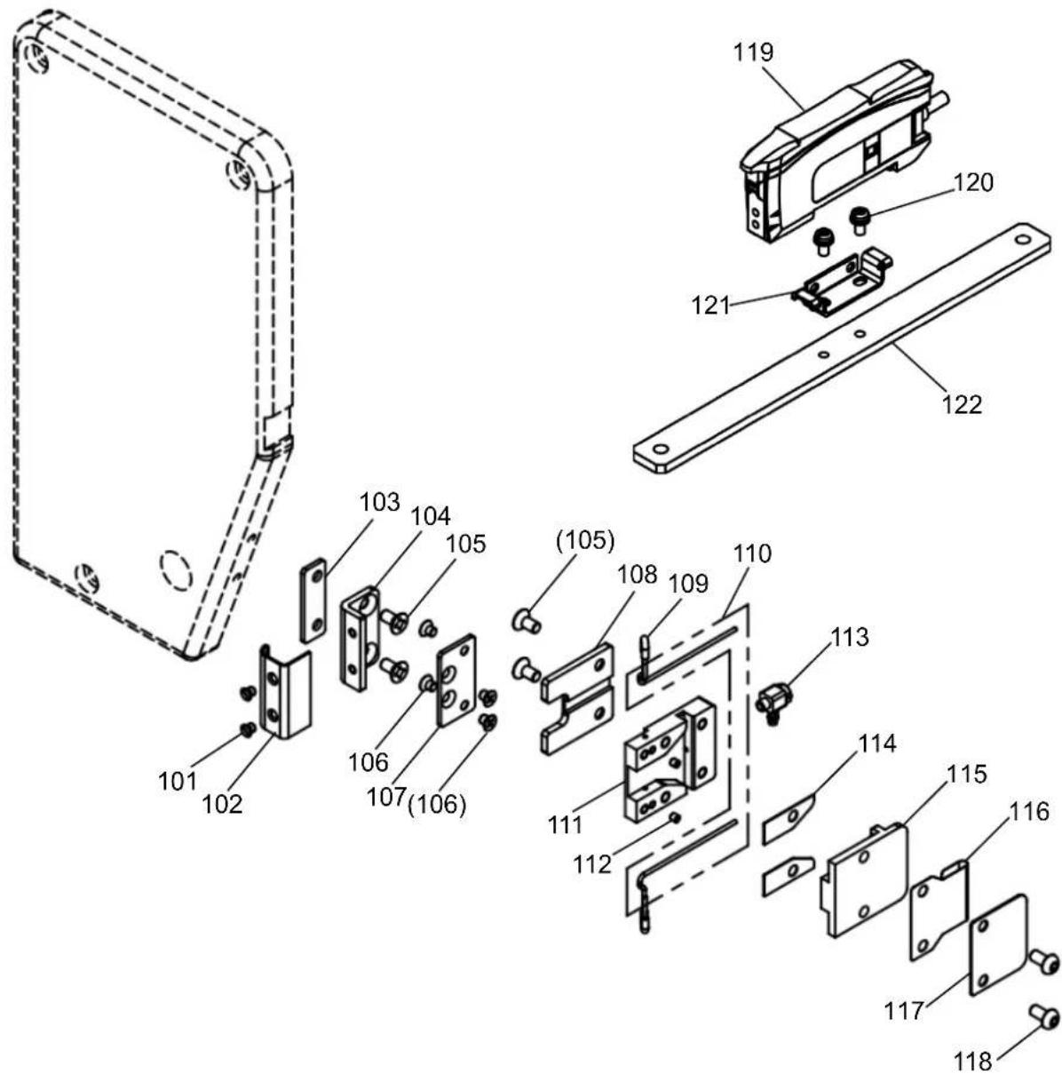
text_image
Exploded view diagram of a mechanical assembly with numbered parts for identification1-2. Solenoid valve parts, Accessories
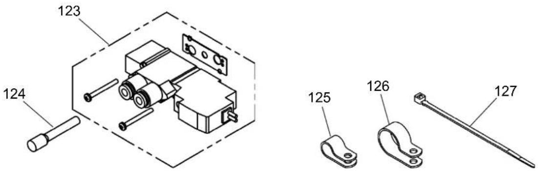
text_image
123 124 125 126 1271-1. Abnormal stitch detector parts, Fiber amp parts (Parts list)
1-2. Solenoid valve parts, Accessories (Parts list)
2. Assembly procedures

CAUTION
★ To work in the presence of residual pressure in the pneumatic circuit It is dangerous. Please work after you remove the residual pressure always. The method of removing the residual pressure, and pull up the handle of the pressure regulating filter regulator, can be done by turning counter-clockwise until the pressure gauge shows 0.
★ When installing removal of parts, please go to turn off the power before. In addition, qualified personnel of electrical work, please be performed by wiring work.
Because the fiber unit (Fig.No.110) is very thin, It may causes break it if applying strong shock. Please handle with care.
2-1. Installing the Abnormal stitch detector
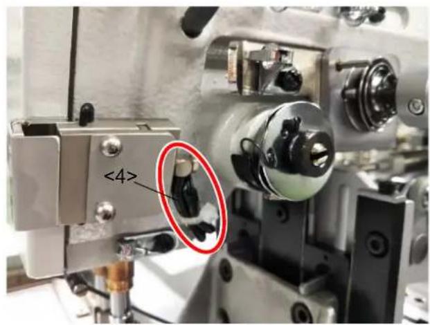
(1) Loosen the screw <1>, and remove the thread guide <2>.
Note Thread guide is attached to only shuttle hook type machines.
(2) Install the base spacer (Fig.No.103) and the bracket (Fig.No.104) by two screws (Fig.No.105) to the face plate < 3> .

text_image
<2> <1>
text_image
<3> 103 104 105(3) Install the Abnormal stitch detector (consist of Fig.No.117 etc.) to the bracket (Fig.No.104) by two screws (Fig.No.106).
(4) Install the cover (Fig.No.102) to the bracket (Fig.No.104) by two screws (Fig.No.101).

text_image
(104) 117 106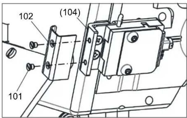
text_image
102 (104) 1012-2. Installing the Fiber amp assy
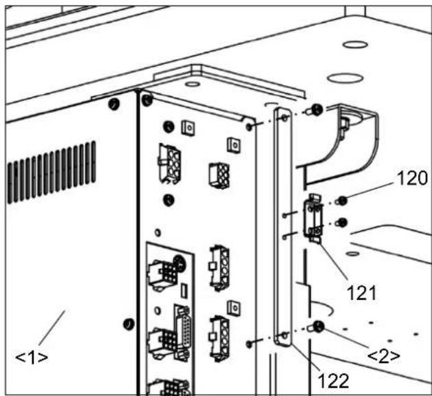
(1) Remove two screws <2> installed in back word the control box <1>, and install the amp bracket (Fig.No.122).
(2) Install the bracket (Fig.No.121) to the amp bracket (Fig.No.122) by two screws (Fig.No.120).
(3) Catch the Fiber amp assy on lower edge of the bracket (Fig.No.121), and install it while pushing up
text_image
<1> 120 121 <2> 122
text_image
(121) 1192-3. Setting of Connector
(1) Remove five screws <2>, and MIF board cover <1>.
(2) Pass the fiber amp assy's connector cable (Fig.No.119) through the side hole of MIF board bracket <3>.
Note If it is difficult to through the connector cable, through it after loosening two screws <5>. While being careful not to damage cables, close the shatter <4> and tighten two screws<5> again.

text_image
<2> <1>(3) Connect the connector to CON6 (CH) on the MIF board.
(4) Attach MIF board cover <1> with Screws <2> again.

text_image
<4> <5> <3> 119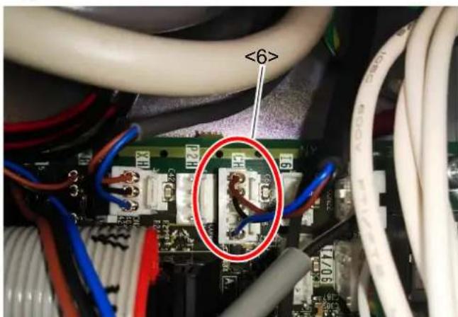
text_image
<6>2-4. Installing Solenoid valve
(1) Pull up the adjustment handle of the Filter regulator <1> located under the table, and Turn counterclockwise until the pressure gauge shows 0.
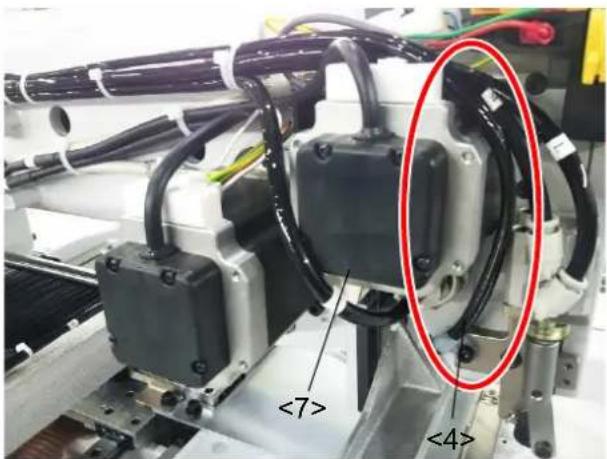
(2) Remove five screws <3>, and motor cover <2>.

text_image
<1>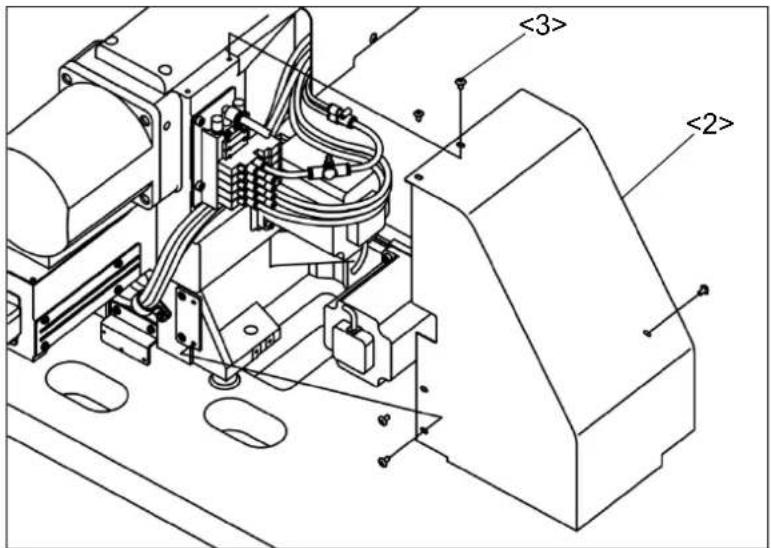
text_image
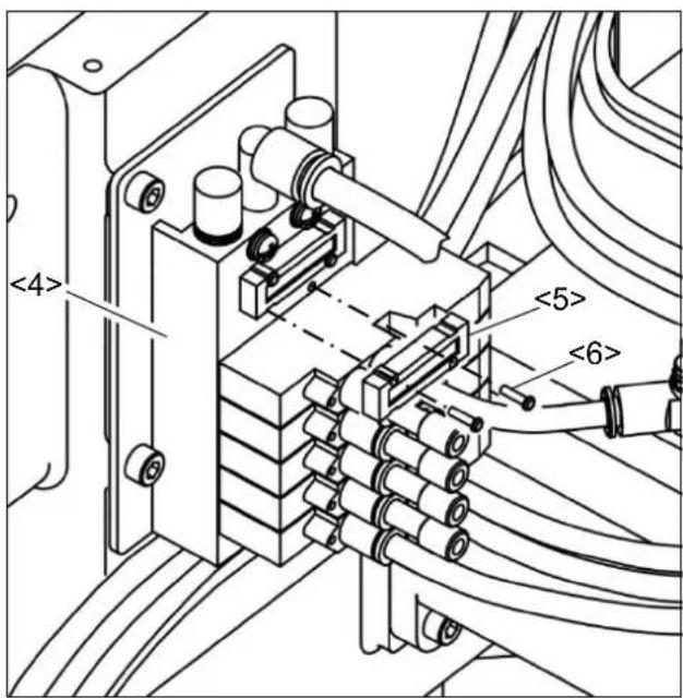
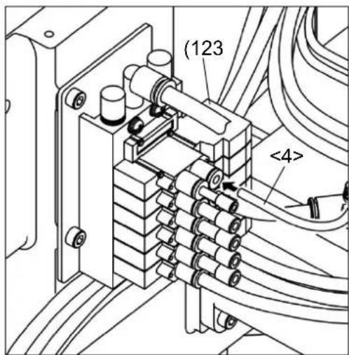
<3> <2>(3) Remove two screws <6> from Solenoid valve <4>, and blanking plate assy.
Note If two or more blanking plate assy are attached, please remove any one.
(4) Install the solenoid valve through gasket with two screws as shown in the figure, where the blanking plate assy <5> was removed (2).
Insert the plug (Fig.No.124) completely the hole on the left side of the solenoid valve.
text_image
<4> <5> <6>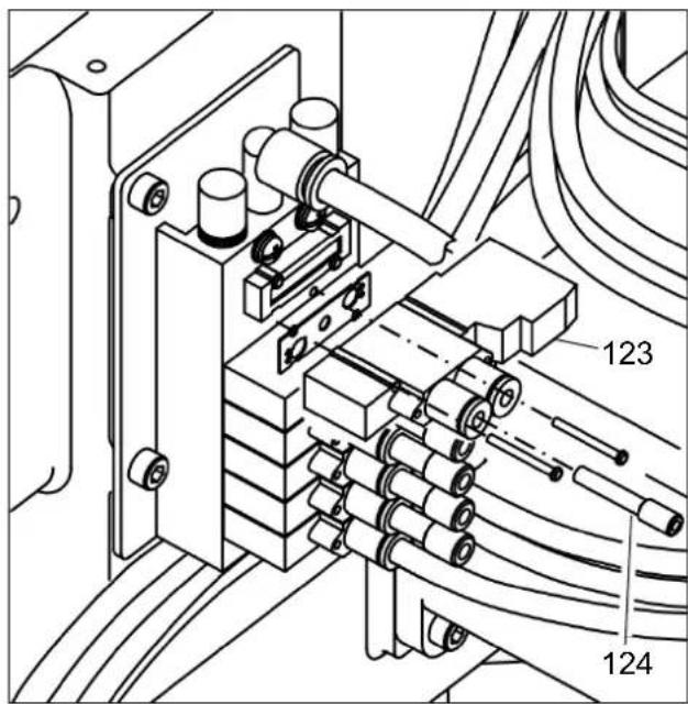
text_image
Technical diagram of a mechanical or electrical assembly with labeled components 123 and 124(5) Unplug 15 pin connector <7> from MIF board.
(6) Pass lead wires (red and black) of the Solenoid valve (Fig.No.123) through the UL tube <8> which the 15 pin connector is connected.
(7) Pass lead wires of the Solenoid valve (Fig.No.123) through the connector cap <9>. Completely insert the lead wire (red) into 15 pin connector 4, lead wire (black) into 5.
(8) Insert the 15 pin connector <7> into MIF board again.

natural_image
Technical line drawing of an electronic device with ports and wiring (no text or symbols)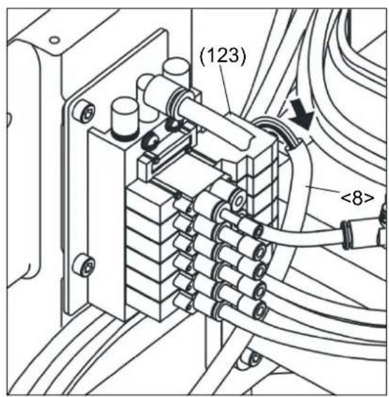
text_image
(123) <8>
text_image
Additional pins Black Red The face to insert Red Black Existing pins <9> <8>2-5. Piping
Piping two 4 tubes (One contains a fiber unit) connected to the abnormal stitch detector installed in [2-1] [Installing the Abnormal stitch detector].
(1) Remove seven screws <3>, head cover <1>, and cover <2>.

text_image
<1> <2> <3>(2) Pull two φ4 tubes <4> to the left through the bottom of the sewing machine arm.
(3) Remove the left screw of the wiper bracket <5> on the left side of the sewing machine.
(4) Pass two 4 tubes < 4> through the nylon clip. Fix the nylon clip (Fig.No.125) to the wiper bracket < 5> by using the screw removed in (3).
Note At this time, manually move the clamp adapter <6> to the front of the sewing machine. Make sure that the clamp adapter and φ4 tubes <4> don't touch each other and fix with the nylon clip.
text_image
<4>
text_image
<4> 125 <6> <5>(5) Pass two 4 tubes from the right side of the motor < 7> . Bundle it with the existing tubes using a cable tie (Fig.No.127), and pipe it to the back of the sewing machine. Note If the existing nylon clip is small, change the nylon clip (Fig.No.126).
text_image
<7> <4>
text_image
126 127(6) Insert the end of 4 tube (One without a fiber unit) completely into the right side of the solenoid valve (Fig.No.123) installed earlier. Note If 4 tube is long, cut and insert
(7) In the reverse order of [2-4] [Installation of solenoid valve] (1), turn the Filter regulator <1> handle clockwise to adjust the air pressure to 0.4 MPa (4kgf/cm²) and push down the handle.
text_image
(123) <4>(8) Pass the other 4 tube < 4> (One with a fiber unit (Fig.No.110)) down through the hole in the table, Insert the fiber unit into the Fiver amp assy (Fig.No.119) mounted on the control box in [2-2] [Installing the Fiber amp assy] in the following procedure.
- Open the protective cover.
- Raise the lock lever.
- Insert the fiber unit completely into the fiber unit insertion
- Return the lock lever and put the protective cover.

text_image
Lock Lever Lock Release Protective Cover 1 2 3 <4> 110 119(9) Pipe the 4 tube passed under the table as same as other cables refer to PLK-J2516-YU/J2516R-YU technical manual [SEWING MACHINE HEAD] [3-10-7] [Fixing of the cables]
(10) Attach the motor cover removed in [2-4] [Installation of Solenoid valve], the head cover <1>, and the cover<2>.
3. How to use
3-1. How to thread the upper thread
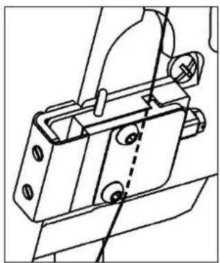
Pass the upper thread through the abnormal stitch detector as shown on the right figure. How to pass the upper thread through other parts is different depends on the model, so confirm the technical manual [SEWING MACHINE HEAD] of each model.
natural_image
Technical line drawing of a mechanical bracket assembly (no text or symbols)3-2. Setting of output customize
(1) Press to (need password) on the standard screen,
open the Output Customize Setting screen.
(2) Set SKAR for output O8.
Note Please refer to the technical manual [Operation Panel] [16] [Input/output setting mode] for details on how to setting of custom output.
3-3. Setting of Fiver amp assy
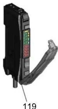
Please set up of Fiver amp assy (Fig.No.119) as follows.
When resetting, turn the power switch on.
3-3-1. Changing of output signal
Change output method to output when a workpiece is in the detection area.
(1) Press button. L/D
(2) Change to L. D
natural_image
Close-up of a black electronic component with a green and red label, showing internal structure and a numbered annotation (119) on the side.3-3-2. Smart tuning [Easy sensitivity setting]
Detect for thread Presence/Absence.
(1) Thread the Abnormal stich detector (consist of Fig.No.117 etc.) attached in right side of machine arm.
(2) Press MENU to ↑ to ✓ on the standard screen, and open the output signal confirmation panel.
(3) Change the panel of [Status reference mode] to [Test output mode]
Note Please refer to the technical manual [Operation Panel] [16] [Input/output setting mode] for checking detail of operation method (2), (3).
(4) On the operation panel, output the port set SKAR, and blow air. Loosen thread as shown on the right figure, and obstruct the sensor light<1> by thread.
In this state, press button.
Note If red value of Fiver amp assy decrease, It is the state obstructing the sensor light.
![JUKI MP-J25-AD - 3-3-2. Smart tuning [Easy sensitivity setting] - 1](/content/2026/06/1220788/images/d39e242d795fc1c721d228bbab8ba539c93a127701ce4274e8cfded87ffb6be6.jpg)
text_image
St IPnT UP DOWN MODE LCE![JUKI MP-J25-AD - 3-3-2. Smart tuning [Easy sensitivity setting] - 2](/content/2026/06/1220788/images/98515d5a33f737f2f43e8c6b2834ac569ec86a0cbc74604cceb3479d191e8d24.jpg)
text_image
110 <1> 117 Air ON![JUKI MP-J25-AD - 3-3-2. Smart tuning [Easy sensitivity setting] - 3](/content/2026/06/1220788/images/58c36e660efc1dd902adda11d8ca6650f82b2b5cfd665ba3a07c1da35ca905af.jpg)
text_image
Air OFF(5) On the operation panel, Stop blowing air by cancelling output SKAR, and pull thread as shown on the
upper right figure.
Check separating thread and sensor light.
In this state, press button again.
![JUKI MP-J25-AD - 3-3-2. Smart tuning [Easy sensitivity setting] - 4](/content/2026/06/1220788/images/3201862e13c39abe39cd0160e911fd446b5d6a18b6686f52c5302574539e6984.jpg)
text_image
SET 2Pnt UP DOWN MODE C/D3-3-3. Setting of threshold level
Press Button and set threshold level "8000".
Threshold level (green) Incident light (red)

text_image
8000 9999 OP DOWN MODE DE3-3-4. Setting of DPC function
DPC is the function restores changing of inner incident light if changing incident light by dust, and keep incident light display constant.
Please set up DPC function after setting 3-3-2[Smart tuning [Easy sensitivity setting]]
(1)Hold button for 3 seconds or more to enter SET mode.
(2)Press button few times to change display to "dPc oFF".

(3)Press button to change to change display to "dPc on".
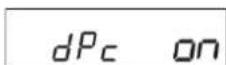
(4)Hold button for 3 seconds or more again to finish setting.
3-3-5. Checking of incident light
Check incident light (refer to the figure of 3-3-3[Setting of threshold level]) value is "9999" when separating thread and sensor light. If value decrease, set incident light to "9999" as follows.
Note If incident light value decrease, erroneous detection may occur.
- Connect the Fiber Unit again
Please refer to 2-5 [Piping] (8), Make sure the Fiber Unit is fully inserted into the Fiber amp assy.
- Clean the abnormal stitch detector
Clean as follows because sensor light is obstructed by collecting the thread waste in the abnormal stitch detector.
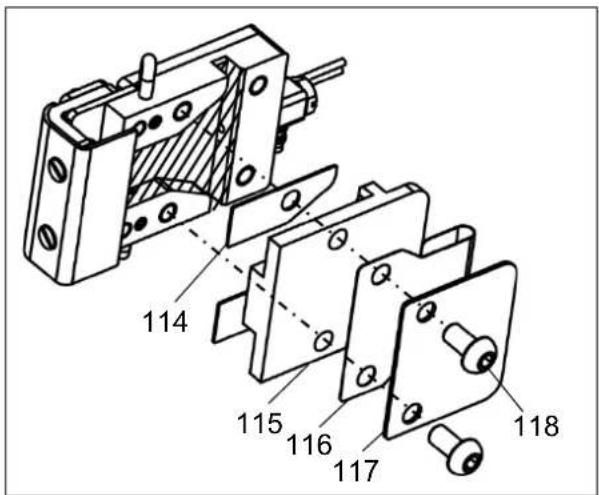
(1) Remove two button bolts (Fig.No.118), the plate (Fig.No.117), the guard (Fig.No.116), the base cover (Fig.No.115), and two spacers (Fig.No.114).
(2) Clean inside the abnormal stitch detector (Hatched area), and remove the thread waste.
(3) Attach spacers (Fig.No.114), the base cover (Fig.No.115), the guard (Fig.No.116), and the plate (Fig.No.117), with button bolts (No.118) again.
When seeing the abnormal stitch detector from above, attach the guard (Fig.No.116) with making an edge of the guard (No.116) contact a protrusion of the base cover (No.115) as shown on the right figure.
Note If an edge of the guard doesn't contact a protrusion of the base cover, thread may be off from the abnormal stitch detector.
text_image
114 115 116 117 118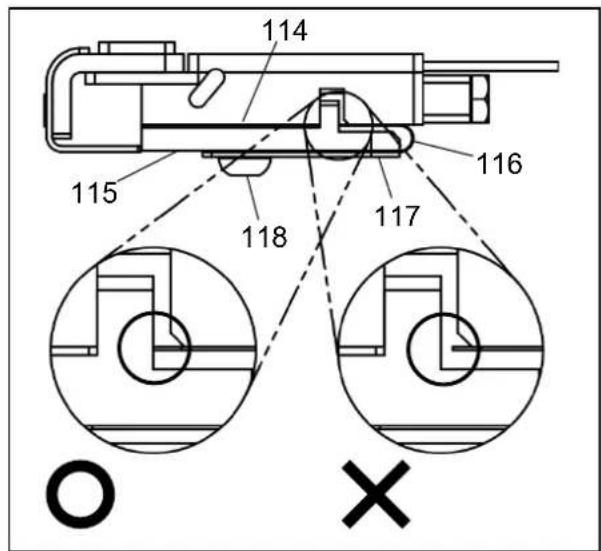
text_image
114 115 116 117 118 O X3-4. How to use the abnormal stitch detector
When using the abnormal stitch detector, set as follows.
(1) Press to Program on the standard screen, and open the Program Mode panel.
(2) Press the ◀ cons to change the page, and press Traceability
(3) Set SKCF, S2CF to "ON". Note If you don't use the abnormal stitch detector, set the above setting to "OF".
3-5. Adjustment of the abnormal stitch detector gap
When sewing by thin thread, reduce a gap in the abnormal stitch detector by removing spacers.
Checking procedure :

text_image
(1) Press to on the standard screen, and open the Motorangle·Home position Sensor·Temperature panel.
(2) Press the ➕️ icon, and open the Motor angle • Home position Sensor • Temperature panel 2.
(3) In this state, start sewing, and can check thread obstructing sensor light if "SENSOR INPUT" CH repeats ON/OFF.

text_image
INPUT STATUS FOR SENSORS MOTOR MAIN 54 ANGLE (Deg) ANALOG ANO 1200 INPUT (AD) AN1 1200 ANALOG DAO 1000 OUTPUT (DA) DA1 1000 POWER SRV 620 SUPPLY PMD 620 SENSOR INPUT CH P2H DTC_U DTC_D BACKAdjustment of a gap procedure
(1) Remove two button bolts (Fig.No.118), the plate (Fig.No.117), the guard (Fig.No.116), and the base cover (Fig.No.115).
(2) Remove two spacers (Fig.No.114), and attach the base cover (Fig.No.115), the guard (Fig.No.116), the plate (Fig.No.117) with button bolts (Fig.No.118) again.
Note When attaching the guard, pay attention to installation position by referring to [3-3-5,2] [Clean the abnormal stitch detector].
Note After adjusting a gap, be sure to check that sensor amp unit receive the light normally by doing [3-3-2] [Smart tuning [Easy sensitivity setting]], [3-3-3] [Setting of threshold level], [3-3-5] [Checking of incident light] again.

text_image
114 115 116 117 1183-6. Setting of the abnormal stitch detection function
Please refer to the technical manual [Operation Panel] [22] [Program mode list] 23[Traceability] for checking detail of the abnormal stitch detection function.
3-6-1. Setting change example of the abnormal stitch detection1
When changing setting of the abnormal stitch detector1, refer to the following example.
Open the Traceability in the Program Mode refer to [3-4] [How to use the abnormal stitch detector].
(1) In the case of erroneous detection occurring without occurring the abnormal stitch.
->Adjust that erroneous detection doesn't occur by increasing set value of SKCS little by little. Note If it is difficult to adjust, use test output of the abnormal stitch detection SKTS.
Checking procedure:
- Press to (need password) on the standard screen,
open the Output Customize Setting screen.
- Set output signal is not used to SKTS.
Note Please refer to the technical manual [Operation Panel] [16][Input/output setting mode] for checking detail of operation 1,2.
- Connect output terminal is set in 2 to the outside lamp.
-> It is possible to substitute for outside lamp by changing Halt signal being on output SSW to SKTS.
- In this state, Sew while working the abnormal stitch detector.
And adjust that lamp doesn't light while standard sewing by increasing set value of SKCS little by little.
(2) In the case of not detecting when the abnormal stitch occur.
-> Adjust that erroneous detection doesn't occur while standard sewing by decreasing set value of SKCS little by little.
(3) If you want not to detect while sewing at less than 1,000rpm.
-> Change set value of SKSP to "1000".
(4) If you want not to detect from start sewing to 6 stitches latter, and from end sewing to 8 stitches former.
-> Change set value of SKN1 to "6" and SKN3 to "8".
(5) If you want to change sewing stop timing by the abnormal stitch detector to when stop upper shaft next time.
-> Change set value of SKTP to "ED".
3-6-2. Setting change example of the abnormal stitch detection2
When changing setting of the abnormal stitch detector2, refer to the following example.
Note It is mentioned only about explanation different from the abnormal stitch detection1.
Open the Traceability refer to [3-5] [Adjustment of the abnormal stitch detector gap].
(1) Change set value of S2CE to the same value as SKCS set at "3-6-1(1), (2).
(2) In the case of erroneous detection occurring without occurring the abnormal stitch.
-> Adjust that erroneous detection doesn't occur by increasing set value of S2FL little by little.