Z76 - Security Camera ACTi - Free user manual and instructions
Find the device manual for free Z76 ACTi in PDF.

User questions about Z76 ACTi
0 question about this device. Answer the ones you know or ask your own.
Ask a new question about this device
Download the instructions for your Security Camera in PDF format for free! Find your manual Z76 - ACTi and take your electronic device back in hand. On this page are published all the documents necessary for the use of your device. Z76 by ACTi.
USER MANUAL Z76 ACTi
natural_image
Abstract geometric design with a red vertical bar and a gray star-like shape on a light background (no text or symbols)Dome Camera
Hardware Manual
Z76
2020/05/18
Table of Contents
Precautions 3
Regulatory Compliance....4
Safety and Compliance Information....6
Introduction 9
List of Models......9
Package Contents....10
Physical Description ...... 11
Installation Procedures 12
Waterproof the RJ-45 Connector 18
Using the Cable Gland....18
Access the Camera 21
Configure the IP Addresses....21
Using DHCP Server to Assign IP Addresses....21
Using the Default Camera IP Address....22
Access the Camera....24
Precautions
Read these instructions
Read all the safety and operating instructions before using this product.
Heed all warnings
Adhere to all the warnings on the product and in the instruction manual. Failure to follow the safety instructions given may directly endanger people, cause damage to the system or to other equipment.
Servicing
Do not attempt to service this product yourself as opening or removing covers may expose you to dangerous voltage or other hazards. Refer all servicing to qualified service personnel.
Trademarks
ACTi and ACTi logo are registered trademarks of ACTi Corporation. All other names and products used in this manual are registered trademarks of their respective companies.
Liability
Every reasonable care has been taken during the writing of this manual. Please inform your local office if you find any inaccuracies or omissions. ACTi will not be held responsible for any typographical or technical errors and reserves the right to make changes to the product and manuals without prior notice.
Regulatory Compliance
Federal Communications Commission Statement

This equipment has been tested and found to comply with the limits for a class B digital device, pursuant to Part 15 of the FCC Rules. These limits are designed to provide reasonable protection against harmful interference in a
residential installation. This equipment generates, uses, and can radiate radio frequency energy and, if not installed and used in accordance with the instructions, may cause harmful interference to radio communications. However, there is no guarantee that interference will not occur in a particular installation. If this equipment does cause harmful interference to radio or television reception, which can be determined by turning the equipment off and on, the user is encouraged to try to correct the interference by one or more of the following measures:
- Reorient or relocate the receiving antenna.
- Increase the separation between the equipment and receiver.
- Connect the equipment into an outlet on a circuit different from that to which the receiver is connected.
- Consult the dealer or an experienced radio/TV technician for help.
Warning: Changes or modifications to the equipment that are not expressly approved by the responsible party for compliance could void the user's authority to operate the equipment.
FCC Conditions
This device complies with part 15 of the FCC Rules. Operation is subject to the following two conditions:
- This device may not cause harmful interference.
- This device must accept any interference received, including interference that may cause undesired operation.
EU Conformity Statement

This product and - if applicable - the supplied accessories too are marked with "CE" and comply therefore with the applicable harmonized European standards listed under the EMC Directive 2014/30/EU, the RoHS Directive 2011/65/EU.

2012/19/EU (WEEE directive): Products marked with this symbol cannot be disposed of as unsorted municipal waste in the European Union. For proper recycling, return this product to your local supplier upon the purchase of equivalent new equipment, or dispose of it at designated collection points. For
more information see: www.recyclethis.info

2006/66/EC (battery directive): This product contains a battery that cannot be disposed of as unsorted municipal waste in the European Union. See the product documentation for specific battery information. The battery is marked with this symbol, which may include lettering to indicate cadmium (Cd), lead
(Pb), or mercury (Hg). For proper recycling, return the battery to your supplier or to a designated collection point. For more information see: www.recyclethis.info
Industry Canada ICES-003 Compliance
This device meets the CAN ICES-3 (B)/NMB-3(B) standards requirements.
Safety and Compliance Information
Installation and removal of the unit and its accessories must be carried out by qualified personnel. You must read all of the Safety Instructions supplied with your equipment before installation and operation.
Installation
- This device is a class A product and may cause radio interference. Take measures if necessary.
- Make sure the camera operates in an environment where the temperature and humidity meet requirements. Keep the camera from excessive pressure, vibration, moisture, dust, and intensive electromagnetic radiation.
- Use a power adapter or a PoE device that meets requirements. Otherwise, the device may be damaged.
- Make sure the length of the power cable between the power adapter and the camera is not too long, otherwise the voltage of the camera is lowered, causing the camera to work abnormally. If it is required to lengthen the power cable, lengthen the cable between the power adapter and the mains.
- Do not hold the tail cable by hand for weight bearing. Otherwise, the cable connector of the camera could be loosened.
- Do not cut the tail cable. Exposed tail cables may cause short circuit and damage the camera.
- When connecting to an external interface, use an existing connection terminal, and ensure that the cable terminal (latch or clamp) is in good condition and properly fastened. Ensure that the cable is not tense during mounting, with a proper margin reserved to avoid poor port contact or loosening caused by shock or shake.
- The end of the tail cable must be kept under good protection. Take waterproof measures to protect the tail cable.
- During the process of transportation, special attention is required for the protection of the transparent dome cover to prevent friction, scratch and contamination, etc. In order to keep the cover clean, do not remove the protective film on the cover during mounting. After mounting is finished, remove the film before the device is powered on.
- Contact professionals for maintenance information. Do not attempt to dismantle the device by yourself. We shall not assume any responsibility for problems caused by unauthorized repair or maintenance.
Maintenance
- If there is dust on the front glass surface, remove the dust gently using an oil-free brush or a rubber dust blowing ball.
- If there is grease or a dust stain on the front glass surface, clean the glass surface gently from the center outward using anti-static gloves or an oil-free cloth. If the grease or the stain still cannot be removed, use anti-static gloves or an oil-free cloth dipped with detergent and clean the glass surface gently until it is removed.
- Do not use organic solvents, such as benzene or ethanol when cleaning the transparent dome cover.

- Never look at the transmit laser while the power is on. Never look directly at the fiber ports and the fiber cable ends when they are powered on.
- Use of controls or adjustments to the performance or procedures other than those specified herein may result in hazardous laser emissions.
Warnings: Serious injury or death may occur if any of the warnings are neglected.
Cautions: Injury or equipment damage may occur if any of the cautions are neglected.
Warnings
- For device with this sticker, this device is intended for installation in a restricted access
location, access can only be gained by service persons or by users who have been instructed about the reasons for the restrictions applied to the location and about any precautions that shall be taken.

- Proper configuration of all passwords and other security settings is the responsibility of the installer and/or end-user.
- In the use of the product, you must be in strict compliance with the electrical safety regulations of the nation and region. Please refer to technical specifications for detailed information.
- Input voltage should meet both the SELV (Safety Extra Low Voltage) and the Limited Power Source with 12 VDC according to the IEC60950-1 standard. Please refer to technical specifications for detailed information.
- Do not connect several devices to one power adapter as adapter overload may cause over-heating or a fire hazard.
- Please make sure that the plug is firmly connected to the power socket. When the product is mounted on wall or ceiling, the device shall be firmly fixed.
- If smoke, odor or noise rise from the device, turn off the power at once and unplug the power cable, and then please contact the service center.
Cautions
• Make sure the power supply voltage is correct before using the camera.
- Do not drop the camera or subject it to physical shock.
- Do not touch sensor modules with fingers. If cleaning is necessary, use clean cloth with a bit of ethanol and wipe it gently. If the camera will not be used for an extended period, please replace the lens cap to protect the sensor from dirt.
- Do not aim the camera at the sun or extra bright places. Blooming or smearing may occur otherwise (which is not a malfunction), and affect the endurance of sensor at the same time.
- The sensor may be burned out by a laser beam, so when any laser equipment is in using, make sure that the surface of sensor will not be exposed to the laser beam.
- Do not place the camera in extremely hot, cold (the operating temperature shall be -30°C to +60°C, or -40°C to +60°C if the camera model has an "H" in its suffix), dusty or damp locations, and do not expose it to high electromagnetic radiation.
• To avoid heat accumulation, good ventilation is required for operating environment.
- Keep the camera away from liquid while in use.
- While in delivery, the camera shall be packed in its original packing, or packing of the same texture.
- Regular part replacement: a few parts (e.g. electrolytic capacitor) of the equipment shall be replaced regularly according to their average enduring time. The average time varies because of differences between operating environment and using history, so regular checking is recommended for all the users. Please contact with your dealer for more details.
- Improper use or replacement of the battery may result in hazard of explosion. Replace with the same or equivalent type only. Dispose of used batteries according to the instructions provided by the battery manufacturer.
- If the product does not work properly, please contact your dealer or the nearest service center. Never attempt to disassemble the camera yourself. (We shall not assume any responsibility for problems caused by unauthorized repair or maintenance.)
Introduction
List of Models
This hardware manual contains the following models:
| Z76 |  | 2MP Outdoor Zoom Dome with D/N, Adaptive IR, Basic WDR, Superior Low Light Sensitivity, Fixed Lens |
Package Contents
Check if the camera package comes with the following items:
| Camera | Cable Gland with Rubber and Washer | Wrench |
 | 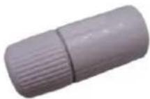 | 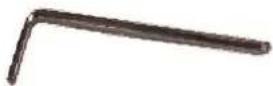 |
| Mounting Screw Kit | Drill Template | Quick Guide & Warranty Card |
 | Drill Template | Warranty Card |
Drill Template
Warranty Card
IMPORTANT: When the camera is taken out from the box, the lens cover is covered by a thin film. DO NOT remove this film. It is used to protect the lens cover from scratches or fingerprint marks which may happen during installation. Remove this film only after the camera is securely installed and all connections are complete.
Physical Description
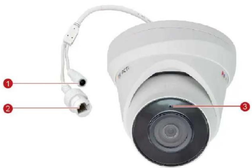
text_image
1 2 3| Item | Description | |
| 1 | DC 12V Power Input Jack | This connector is used to connect to a DC 12V power adapter if a non-PoE network connection will be used. |
| 2 | Ethernet Port | Connects to a network using an Ethernet cable. |
| 3 | Built-in Microphone | Receives audio input. |
Installation Procedures
The images on this section are for reference only; actual lens and cables may vary.
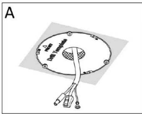
- Locate the positions of the holes; paste the drill template stickers on the ceiling and drill according to the images below.

text_image
A Ø5.5mm Ø40mmA. Cables Going Through the Ceiling

text_image
B Ø5.5mm 100mm Dial TranspositionB. Cables Going Along the Ceiling
-
Insert the plastic anchors.
-
Twist the cosmetic ring of the camera.

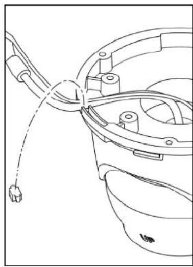
natural_image
Diagram showing a device component before and after assembly, with no visible text or symbols- Route the cables through the ceiling (A) or along the ceiling (B).
text_image
A Power Dial Transducers
text_image
B A Drip TranspoidsIf the cable will be routed along the wall, then cut off the camera tab to where the cable will pass through.
natural_image
Technical line drawing of a mechanical component with no visible text or symbols- Secure the ground screw.
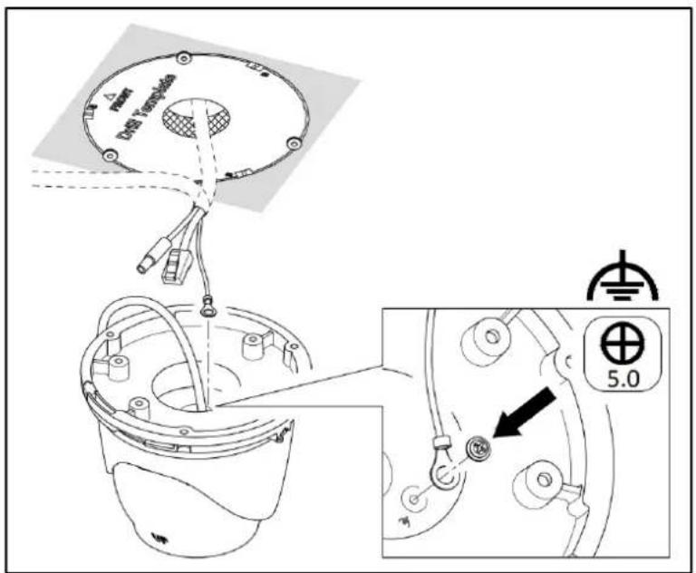
text_image
Δ max Unit Template 5.0- Connect the cables. See ** for the detailed description on how to waterproof the Ethernet cable.
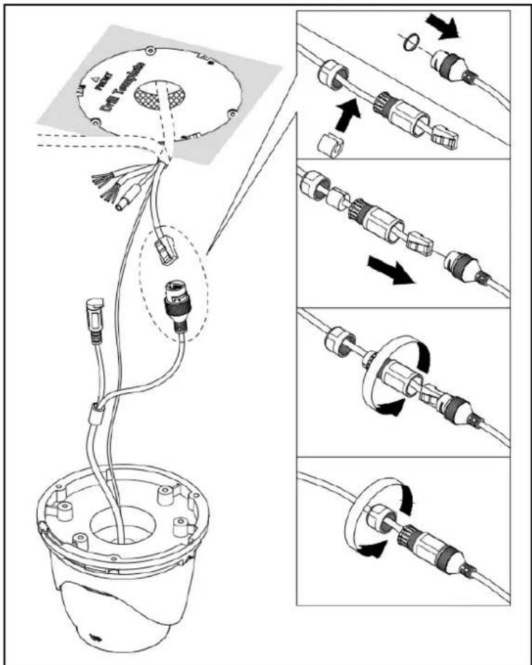
text_image
Technical diagram illustrating cable assembly and component alignment for a device, with labeled parts and directional arrows indicating assembly steps.- (Optional) If the camera will be connected to the DC 12V power, connect the power cable and wrap the cable with waterproof tape.
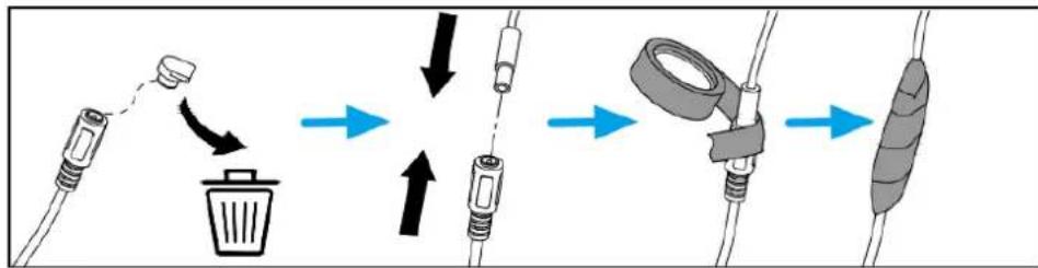
flowchart
graph TD
    A["Trash Bin"] --> B["Recycle Bin"]
    B --> C["Assembly Cable"]
    C --> D["Tape Capture"]
    D --> E["Packaging Cable"]
NOTE: If the DC12V connector will not be used, wrap it also in waterproof tape to avoid short circuiting the connector.
- Mount the camera to the ceiling using the three (3) bundled screws.

text_image
Power Ground T compensation UP- Access the camera to see the viewing angle (see Access the Camera on page 21). Then, adjust the camera tilt and rotation, as needed.

text_image
0° - 75° 0° - 360°- To pan the camera, loosen the set screw using the bundled wrench. Then, rotate the camera body.
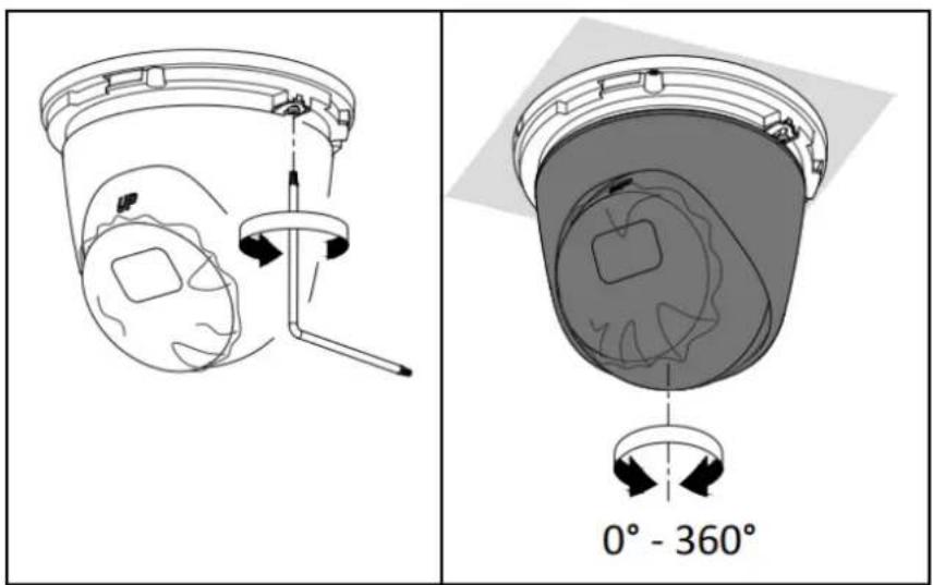
text_image
0° - 360°- Tighten the screw to fix the camera position.

natural_image
Diagram of a mechanical device with a rotating arm and handle, showing internal components (no text or symbols)- Attach the cosmetic ring to complete the installation.

natural_image
Technical line drawing of a mechanical component with cross-sectional views and directional arrows (no text or symbols)Waterproof the RJ-45 Connector
The camera and the pre-installed network cable, "pigtail", are resistant to salt, water, weak acid, alcohol, oil, grease and other common solvents. If the camera will be installed indoors, simply connect the network side cable to the camera Ethernet port.
However, if the camera will be installed outdoors, ensure that the cable connections are protected from different environmental factors. Use the bundled cable gland to protect the Ethernet connection and use a waterproof tape to protect other cable connections.
DISCLAIMER: ACTi will not be responsible for camera damage caused by water entering the cable connections.
Using the Cable Gland
This section describes how to waterproof the cable-out or "pigtail" of the camera using the bundled cable gland. Before connection, prepare an exterior-grade Ethernet cable with RJ-45 connector.
Perform the following to waterproof the "pigtail" using the cable gland:
- Attach the washer to the Ethernet connector of the camera.

natural_image
Two-step diagram showing a hand holding a white connector being adjusted to form a white plug with red and white bands (no text or symbols)- Detach the clamping nut and sealing insert from the gland body:
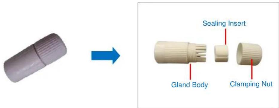
text_image
Sealing Insert Gland Body Clamping Nut- Insert the clamping nut into the Ethernet cable.
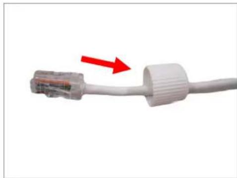
natural_image
Close-up of a white USB cable with a red arrow pointing to its connector (no text or symbols visible)- Insert the sealing insert through the Ethernet cable.

natural_image
Close-up of a hand holding a white USB cable with a small connector (no text or symbols visible)- Insert the cable through the gland body.
natural_image
Two-step diagram showing a hand holding a white cable with a connector, before and after assembly (no text or symbols)- Push the sealing insert into the gland body.

natural_image
Close-up of a hand holding a white plastic tool with a red arrow pointing to a connector (no text or symbols visible)- Connect the RJ-45 connector to the camera connector.

natural_image
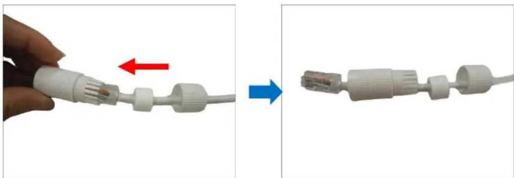
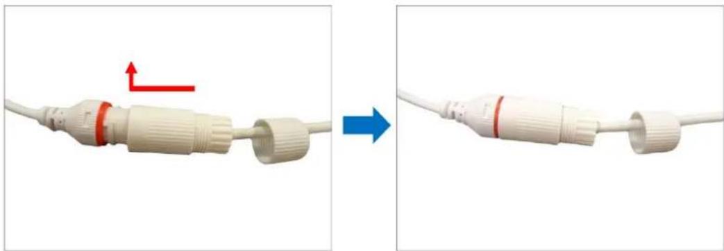
Close-up of a white cable with two connectors and a red arrow pointing to one connector (no text or symbols visible)- Attach the gland body to the camera connector.
natural_image
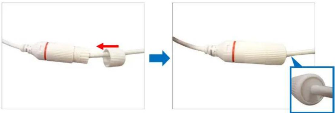
Two-step diagram showing a white cable connector being adjusted, with red and blue arrows indicating direction (no text or symbols)- Attach the clamping nut to the gland body to complete the cable solution.
natural_image
Two-step diagram showing a white cable connector being inserted into a terminal, with red arrows indicating the insertion direction (no text or symbols present)NOTE: Make sure the clamping nut is tightly attached to the cable gland body and the sealing insert is squeezed tightly.
Access the Camera
Configure the IP Addresses
In order to be able to communicate with the camera from your PC, both the camera and the PC have to be within the same network segment. In most cases, it means that they both should have very similar IP addresses, where only the last number of the IP address is different from each other. There are 2 different approaches to IP Address management in Local Area Networks – by DHCP Server or Manually.
Using DHCP Server to Assign IP Addresses
If you have connected the computer and the camera into the network that has a DHCP server running, then you do not need to configure the IP addresses at all – both the camera and the PC would request a unique IP address from DHCP server automatically. In such case, the camera will immediately be ready for the access from the PC. The user, however, might not know the IP address of the camera yet. It is necessary to know the IP address of the camera in other to be able to access it by using a Web browser.
If you work with our cameras regularly, then there is even a better way to discover the cameras in the network – by using IP Utility. The IP Utility is a light software tool that can not only discover the cameras, but also list lots of valuable information, such as IP and MAC addresses, serial numbers, firmware versions, etc, and allows quick configuration of multiple devices at the same time.
The IP Utility can be downloaded for free from http://www.acti.com/IP_Utility
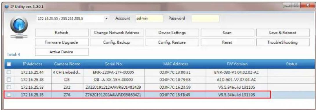
With just one click, you can launch the IP Utility and there will be an instant report as follows:
text_image
IP Utility ver. S.0.0.1 172.16.25.30 / 255.255.255.0 Account admin Password Refresh Change Network Address Device Settings Scan Save & Reboot Firmware Upgrade Config. Backup Config. Restore Reset TroubleShooting Active Device Total: 4 IP Address Camera Name Serial No. MAC Address PW Version Status 172.16.25.44 4 CH Embedd... ENR-220PA-17F-00005 00:0F:7C:13:80:31 ENR-030-V5.04.02.02-AC 172.16.25.38 I28 I28-A-XX-15H-00009 00:0F:7C:10:79:E8 A1D-501-V7.07.04-AC 172.16.25.53 Z32 Z3220191212AAWRE01482429 00:0F:7C:16:23:59 V5.5.84build 191105 172.16.25.35 Z76 Z7620191203AAWRD95868421 00:0F:7C:15:FB:45 V5.5.84build 191105You can quickly see the camera model in the list. Double-click on the IP address to automatically launch the default browser of the PC with the IP address of the target camera filled in the address bar of the browser already.
Using the Default Camera IP Address
If there is no DHCP server in the given network, the user may have to assign the IP addresses to both PC and camera manually to make sure they are in the same network segment.
When the camera is plugged into the network and it does not detect any DHCP services, it will automatically assign itself a default IP:
192.168.0.100
Whereas the default port number would be 80. In order to access that camera, the IP address of the PC has to be configured to match the network segment of the camera.
Manually adjust the IP address of the PC:
In the following example, based on Windows 7, we will configure the IP address to
192.168.0.99 and set Subnet Mask to 255.255.255.0 by using the steps below:

text_image
1 All Control Panel Items ▶ Network and Sharing Center ▶ Search Control Panel Control Panel Home Change adapter settings Change advanced sharing settings View your basic network information and set up connections SISO_NP_PC1 (This computer) Network Internet See full map View your active networks Connect or disconnect Network Work network Access type: Internet Connections Local Area Connection Change your networking settings Set up a new connection or network Set up a wireless, broadband, dial-up, ad hoc, or VPN connection; or set up a router or access print. Connect to a network Connect or reconned to a wireless, wired, dial-up, or VPN network connection. Choose homegroup and sharing options Access files and printers located on other network computers, or change sharing settings.
text_image
2 Organize Disable this network device Diagnosis Local Area Connection Network Intel(R) & Disable Status Diagnose Bridge Connections Create Shortcut Delete Rename Properties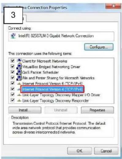
text_image
3 Connect using Intel(R) 32567LM-3 Gigabit Network Connection Configure... This connection uses the following items: ✓ Client for Microsoft Networks ✓ VisualBox Edged Networking Driver ✓ QoS Packet Scheduler ✓ File and Printer Sharing for Microsoft Networks ✓ Internet Protocol Version 6 (TCP/Pv5) ✓ Internet Protocol Version 4 (TCP/Pv4) ✓ Link-Layer Topology Discovery Mapper I/O Driver ✓ Link-Layer Topology Discovery Responder Install Uninstall Properties Description Transmission Control Protocol/Internet Protocol. The default wide area network protocol that provides communication across diverse interconnected networks. OK Cancel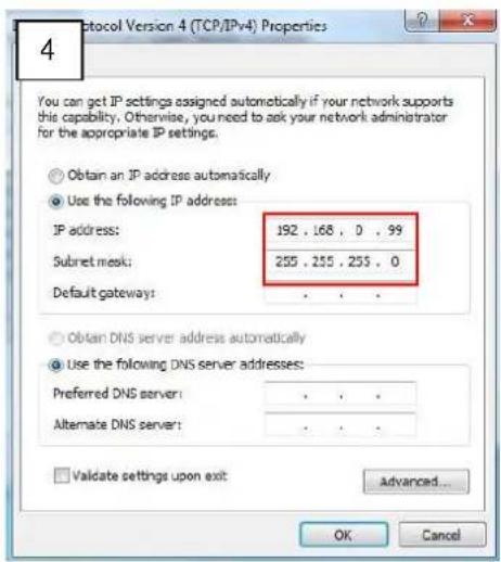
text_image
4 You can get IP settings assigned automatically if your network supports this capability. Otherwise, you need to ask your network administrator for the appropriate IP settings. Obtain an IP address automatically Use the following IP address: IP address: 192 . 168 , 0 , 99 Subset mask: 255 . 255 . 255 , 0 Default gateway: . Obtain DNS server address automatically Use the following DNS server addresses: Preferred DNS server: . Alternate DNS server: . Validate settings upon exit: Advanced... OK CancelManually adjust the IP addresses of multiple cameras:
If there are more than 1 camera to be used in the same local area network and there is no DHCP server to assign unique IP addresses to each of them, all of the cameras would then have the initial IP address of 192.168.0.100, which is not a proper situation for network devices – all the IP addresses have to be different from each other. The easiest way to assign cameras the IP addresses is by using IP Utility:

text_image
IP. Utility P.Address / NetMask: 172.16.28.192 / 255.255.255.0 Refresh Device Settings Change Network Address Firmware Upgrade Config. Backup Config. Restore Reset Save&Reboot Total: 56 Account admin Password 123456 Http Port 80 IP Address NAC Address FWV Version Model Serial No Multicast IP Status 172.16.26.2 00:0F 7C:07.DE 65 A1D-311-V5.07.05-AC Henspheric Camera KCM3811 228.5.6.1 172.16.26.4 00:0F 7C:08.17.C2 A1D-310-V4.12.02-AC Mega IP Camera TCM1111 228.5.6.1 172.16.26.6 00:0F Change Network Address Dynamic P Address Static P Address Starting IP Address 192 . 108 . 0 . 101 Netmask 255 . 255 . 255 . 0 Gateway 192 . 108 . 0 . 254 Apply 172.16.26.57 00:0F 7C:04.87.A7 A1D-310-V4.12.09-AC Video Server TCD2100 228.5.6.1 172.10.26.61 00:0F 7C:04.32.E3 A1D-310-V4.12.09-AC Megapixel P Camera TCM1231 228.5.6.1With the procedure shown above, all the cameras will have unique IP addresses, starting from 192.168.0.101. In case there are 20 cameras selected, the last one of the cameras would have the IP 192.168.0.120.
Later, by pressing the "Refresh" button of the IP Utility, you will be able to see the list of cameras with their new IP addresses.

Please note that it is also possible to change the IP addresses manually by using the Web browser. In such case, please plug in only one camera at a time, and change its IP address by using the Web browser before plugging in the next one. This way, the Web browser will not be confused about two devices having the same IP address at the same time.
Access the Camera
Now that the camera and the PC are both having their unique IP addresses and are under the same network segment, it is possible to use the Web browser of the PC to access the camera.
You can use Microsoft Internet Explorer to access the camera
When using Internet Explorer browser, the ActiveX control for video stream management will be downloaded from the camera directly – the user just has to accept the use of such control when prompted so. No other third party utilities are required to be installed in such case.
The following examples in this manual are based on Internet Explorer browser in order to cover all functions of the camera.
Assuming that the camera's IP address is 192.168.0.100, you can access it by opening the Web browser and typing the following address into Web browser's address bar:
http://192.168.0.100
Upon successful connection to the camera, the user interface would appear together with the login page. The HTTP port number was not added behind the IP address since the default HTTP port of the camera is 80, which can be omitted from the address for convenience.

text_image
http://192168.0.100 Web ConfiguratorEnter the default values, then click Login to enter the user interface:
Account = admin
Password = Aa123456!

text_image
|ACTi SECURITY PHONE Password Forgot password? Login
ACTi
Connecting Vision
Copyright © 2020, ACTi Corporation All Rights Reserved
7F, No. 1, Alley 20, Lane 407, Sec. 2, Ti-Ding Blvd., Neihu District, Taipei, Taiwan 114, R.O.C.
TEL: +886-2-2656-2588
FAX: +886-2-2656-2599
Email: sales@acti.com