B934 - Security Camera ACTi - Free user manual and instructions
Find the device manual for free B934 ACTi in PDF.

User questions about B934 ACTi
0 question about this device. Answer the ones you know or ask your own.
Ask a new question about this device
Download the instructions for your Security Camera in PDF format for free! Find your manual B934 - ACTi and take your electronic device back in hand. On this page are published all the documents necessary for the use of your device. B934 by ACTi.
USER MANUAL B934 ACTi
natural_image
Abstract geometric design with a red vertical bar and a gray star-like shape on a light background (no text or symbols)Indoor PTZ /
Speed Dome Camera
Hardware Manual
B913, B923, B934, I92, I92, I912
Ver. 2018/08/09
Table of Contents
Precautions 4
Safety Instructions....6
Introduction 7
List of Models....7
Package Contents......8
Physical Description 9
B913, B923, B934....9
I91, I92, I912....10
Before Installation 11
Unpacking the Camera....11
Preparing the Power Adapter.... 12
Preparing the DI/DO Connector 14
Installation Procedures 17
Mounting Solutions 17
Other Mounting Accessories 19
Mounting on the Ceiling 20
Using the Bundled Surface Mount 20
Using the Flush Mount 23
Using the Pendant Mount....29
Mounting on Straight Wall 33
Using the L-Type Wall Mount 33
Other Accessories and Adjustments 36
How to Install / Remove the Memory Card.... 36
B913, B923, B934 36
191, 192, 1912....37
How to Remove the Memory Card....37
How to Replace the Dome Cover 38
How to Reset the Camera 39
Accessing Camera 40
Configure the IP Addresses 40
Access the Camera.... 44
Precautions
Read these instructions
Read all the safety and operating instructions before using this product.
Heed all warnings
Adhere to all the warnings on the product and in the instruction manual. Failure to follow the safety instructions given may directly endanger people, cause damage to the system or to other equipment.
Servicing
Do not attempt to service this product yourself as opening or removing covers may expose you to dangerous voltage or other hazards. Refer all servicing to qualified service personnel.
Trademarks
ACTi and ACTi logos are registered trademarks of ACTi Corporation. All other names and products used in this manual are registered trademarks of their respective companies.
Liability
Every reasonable care has been taken during the writing of this manual. Please inform your local office if you find any inaccuracies or omissions. ACTi will not be held responsible for any typographical or technical errors and reserves the right to make changes to the product and manuals without prior notice.
Federal Communications Commission Statement

This equipment has been tested and found to comply with the limits for a class B digital device, pursuant to Part 15 of the FCC Rules. These limits are designed to provide reasonable protection against harmful interference in a
residential installation. This equipment generates, uses, and can radiate radio frequency energy and, if not installed and used in accordance with the instructions, may cause harmful interference to radio communications. However, there is no guarantee that interference will not occur in a particular installation. If this equipment does cause harmful interference to radio or television reception, which can be determined by turning the equipment off and on, the user is encouraged to try to correct the interference by one or more of the following measures:
- Reorient or relocate the receiving antenna.
- Increase the separation between the equipment and receiver.
- Connect the equipment into an outlet on a circuit different from that to which the receiver is connected.
- Consult the dealer or an experienced radio/TV technician for help.
Warning: Changes or modifications to the equipment that are not expressly approved by the responsible party for compliance could void the user's authority to operate the equipment.
European Community Compliance Statement

This product has been tested and found to comply with the limits for Class B Information Technology Equipment according to European Standard EN 55022
and EN 55024. In a domestic environment, this product may cause radio interference in which cause the user may be required to take adequate measures.
Safety Instructions
Don't use the power supply with other voltages
This device is likely to be damaged or damage other equipments / personnel, if you use a power supply with different voltage than the one included with this device. All warranty of this product will be voided in the situations above.
Cleaning
Disconnect this product from the power supply before cleaning.
Accessories and Repair Parts
Use only the accessories and repair parts recommended by the manufacturer. Using other attachments not recommended by the manufacturer may cause hazards.
Water and Moisture
Do not use this product near water, for example, near a bathtub, washbowl, kitchen sink, or laundry tub, in a wet basement, or near a swimming pool and the likes. Install this product as well as other devices (such as PoE injector, alarm, etc.) in a dry place protected from weather.
Servicing
Do not attempt to service this product yourself. Refer all servicing to qualified service personnel.
Damage Requiring service
Disconnect this product from the power supply immediately and refer servicing to qualified service personnel under the following conditions.
1) When the power-supply cord or plug is damaged
2) If liquid has been spilled, or objects have fallen into the product.
3) If the product has been directly exposed to rain or water.
4) If the product does not operate normally by following the operating Instructions in this manual. Adjust only those controls that are covered by the instruction manual, as an improper adjustment of other controls may result in damage, and will often require extensive work by a qualified technician to restore the product to its normal operation.
Safety Check
Upon completion of any service or repairs to this product, ask the service technician to perform safety checks to determine if the product is in proper operating condition.
Introduction
List of Models
This hardware manual contains the following models:
| B913 |  | 5MP, Indoor Speed Dome, Day / Night, Extreme WDR, Superior Low Light Sensitivity, 30x optical |
| B923 |  | 3MP, Video Analytics Indoor Speed Dome, Day / Night, Extreme WDR, Superior Low Light Sensitivity, 30x optical |
| B934 |  | 2MP Video Analytics Indoor Speed Dome with D/N, Extreme WDR, SLLS, 30x Zoom lens |
| I91 |  | 1MP Indoor PTZ with D/N, Extreme WDR, SLLS, 30x Zoom lens |
| I92 |  | 2MP Indoor PTZ with D/N, Extreme WDR, SLLS, 30x Zoom lens |
| I912 |  | 4MP Indoor PTZ with D/N, Advanced WDR, SLLS, 33x Zoom lens |
Package Contents
| Camera | Power Adapter | Universal Plug Converter |
 |  |  |
| Surface Mount | Mounting Screw Kit | Fixing Bracket |
 |  |  |
| Drill Template | Terminal Block (for Power) | Terminal Block (for DIO/DO) |
 |  |  |
| Quick Installation Guide | Warranty Card | |
 |  | |
Physical Description
B913, B923, B934

text_image
Connectors View Internal View 1 2 3 4 5 6 7 8| Item | Description | |
| 1 | Digital Input / Output (DI/DO) | Connects to digital input or output devices, such as an alarm trigger, panic button, etc. Digital Input (DI) and Digital Output (DO) devices are used in applications like motion detection, event triggering, alarm notifications, etc. Please refer toPreparing the DI/DO Connectoron page 14 for information on how to connect DI/DO devices to your camera. |
| 2 | Audio IN / Audio OUT Jacks | The Audio IN jack connects to an audio input device, such as a microphone with built-in amplifier. The Audio OUT jack connects to an audio output device, such as a speaker.NOTE:Make sure that the connected audio input device has a built-in amplifier. Connecting an ordinary microphone will dwarf sounds and will result in inaudible recording. |
| 3 | DC 12V Power Input | In case the camera is connected to a non-PoE (Power over Ethernet) switch, use this connector to connect the camera to an external power adaptor. SeePreparing the Power Adapteron page 12 for information. |
| 4 | Ethernet Port | Connects to a network using a standard Ethernet cable. |
| 5 | Memory Card Slot | For local recording, insert a memory card (not included) into the slot with the metallic contacts facing down the camera.NOTE:Supports only microSDHC and microSDXC cards. |
| 6 | Reset Button | The Reset Button is used to restore the factory default settings of the camera, including the administrator's password. Press and hold the Reset button for 5 seconds or until the Power LED goes off. SeeHow to Reset the Cameraon page 39. |
| 7 | Power LED | The Power LED lights red when the camera is powered up. |
I91, I92, I912

text_image
Connectors View Internal View 1 2 3 4 5 6 7| Item | Description | |
| 1 | Digital Input / Output (DI/DO) | Connects to digital input or output devices, such as an alarm trigger, panic button, etc. Digital Input (DI) and Digital Output (DO) devices are used in applications like motion detection, event triggering, alarm notifications, etc. Please refer toPreparing the DI/DO Connectoron page 14 for information on how to connect DI/DO devices to your camera. |
| 2 | Audio IN / Audio OUT Jacks | The Audio IN jack connects to an audio input device, such as a microphone with built-in amplifier. The Audio OUT jack connects to an audio output device, such as a speaker.NOTE:Make sure that the connected audio input device has a built-in amplifier. Connecting an ordinary microphone will dwarf sounds and will result in inaudible recording. |
| 3 | DC 12V Power Input | In case the camera is connected to a non-PoE (Power over Ethernet) switch, use this connector to connect the camera to an external power adaptor. SeePreparing the Power Adapteron page 12 for information. |
| 4 | Ethernet Port | Connects to a network using a standard Ethernet cable. |
| 5 | Memory Card Slot | For local recording, insert a memory card (not included) into the slot with the metallic contacts facing down the camera.NOTE:Supports only microSDHC and microSDXC cards. |
| 6 | Reset Button | The Reset Button is used to restore the factory default settings of the camera, including the administrator's password. Press and hold the Reset button for 5 seconds or until the Power LED goes off. SeeHow to Reset the Cameraon page 39. |
| 7 | Power LED | The Power LED lights red when the camera is powered up. |
Before Installation
Unpacking the Camera
NOTE: To avoid scratches or leaving fingerprints on the dome cover, it is recommended to retain the plastic covering the dome cover until the camera is completely installed. However, the plastic has been removed on the pictures in this documentation to show clarity of the procedures being described.
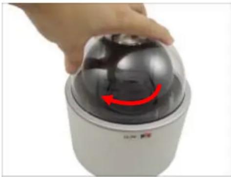
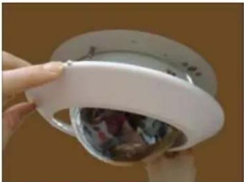
- Rotate the dome cover counter-clockwise to remove it.

- Remove the Styrofoam.

natural_image
Hand placing a white plastic film onto a black spherical device (no text or symbols visible)- Rotate the dome cover clockwise to attach it.
natural_image
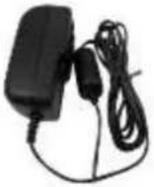
Hand holding a dome-shaped security camera with red directional arrow indicating rotation (no text or symbols)Preparing the Power Adapter
In case of using a non-PoE switch or your PoE switch has limited power supply, you can use the bundled power adapter and directly connect the camera to a power outlet. The power adapter must be connected to the supplied terminal block before use.
To do this, follow the procedures below:
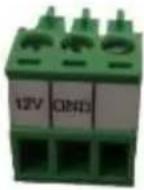
- Loosen the screws of the 12V and GND pins of the power terminal block.
natural_image
Close-up of a green electrical connector being inserted with a black tool (no text or symbols visible)- Take note that the power adapter cable has two (2) different wires:
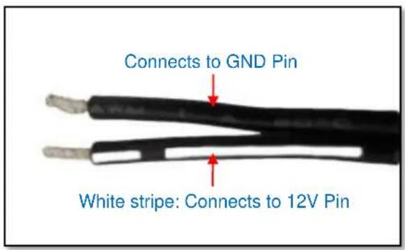
text_image
Connects to GND Pin White stripe: Connects to 12V Pin- Connect the wire with the white stripe to the 12V pin and the other to the GND pin.

natural_image
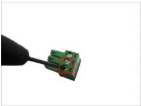
Close-up of a green printed circuit component being held by wires, showing a blue arrow indicating transformation (no text or symbols visible)- Tighten the screws of the 12V pin and the GND pins to secure the wire connection.
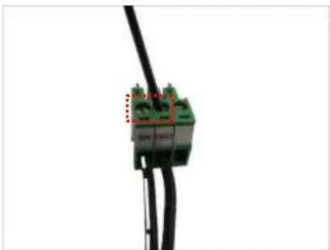
natural_image
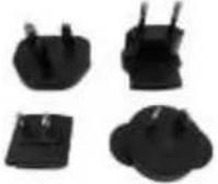
Close-up of a black cable with green connectors and red dashed boxes, no visible text or symbols- Attach one of the bundled adapter plugs suitable in your location.
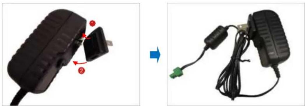
natural_image
Two-step diagram showing a black plastic device being adjusted to a cable with a green connector, both without any text or symbols.Preparing the DI/DO Connector
Depending on your surveillance needs, you may connect digital input or output devices to your camera to trigger events or notifications.
Digital Input (DI) devices can be used to notify the camera about an activity in the camera site. DI can be triggers of events. For example, you can connect a “panic button” to the camera; as such when the panic button is pressed, the alarm signal will be sent through the camera. Other common DI device applications are emergency button, smoke detector, passive infrared sensor, etc.
Digital Output (DO) devices are external devices that are activated by the camera upon an event inside the camera. For example, you can connect an “alarm horn” to the camera; as such when an event occurs inside the camera (e.g. detected intruder), the alarm horn will sound. Other common DO device applications are motion-triggered lights, electric fence, magnetic door locks, etc.
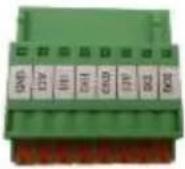
You can connect up to two DI and two DO devices to your camera.

text_image
GND A11 110 100 GND A21 200DTo connect input devices (DI), map the pins to one of the pin combinations below:
| Device | Mapping Instructions | |
| Digital Input 1 (DI1) | GND | Connect the wires of the first input device to GND and DI1. |
| DI1 | ||
| Digital Input 2 (DI2) | GND | Connect the wires of the second input device to GND and DI2. |
| DI2 | ||
To connect output devices (DO), map the pins to one of the pin combinations below:
| Device | Pin | Mapping Instructions |
| Digital Output 1 (DO1) | 12V | Connect the wires of the first output device to 12V and DO1. |
| DO1 | ||
| Digital Output 2 (DO2) | 12V | Connect the wires of the second output device to 12V and DO2. |
| DO2 |
The table below shows the DI/DO connection specifications:
| Device | |||
| DI | Connection design | TTL - compatible logic levels | |
| Voltage | To trigger (low) | Logic level 0: 0V ~ 0.4V | |
| Normal (high) | Logic level 1: 3.1V ~ 30V | ||
| Current | 10mA ~ 100mA | ||
| DO | Connection design | Transistor (Open Collector) | |
| Voltage & Current | < 24V DC, < 50mA | ||
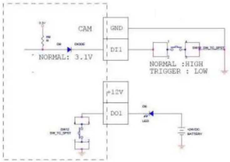
Typical Connection
Based on these specifications, if the DI device has a voltage of 0V \~ 30V or the DO device has a voltage of < 24V (< 50mA), then the camera can supply internal power to these devices and there is no need to connect the DI/DO device to an external power source.
In this case, use the GND and DI1 pins to connect a DI device and use the 12V and DO1 pins to connect a DO device. See wiring scheme below:
text_image
CAM GND DI1 NORMAL: 3.1V +12V DO1 DAY2 SW_TC_SPST ON LED ON/DC BATTERYConsequently, to connect a second DI or DO device, use the GND and DI2 pins to connect a second DI device, and the 12V and DO2 to connect a second DO device.
High Voltage DO Device Connection
Even though the camera provides 12V power, this may not be enough for some high voltage DO devices, such as a ceiling light or a motor that opens or closes a gate. In this case, there is a need to connect an external relay. See wiring scheme below:
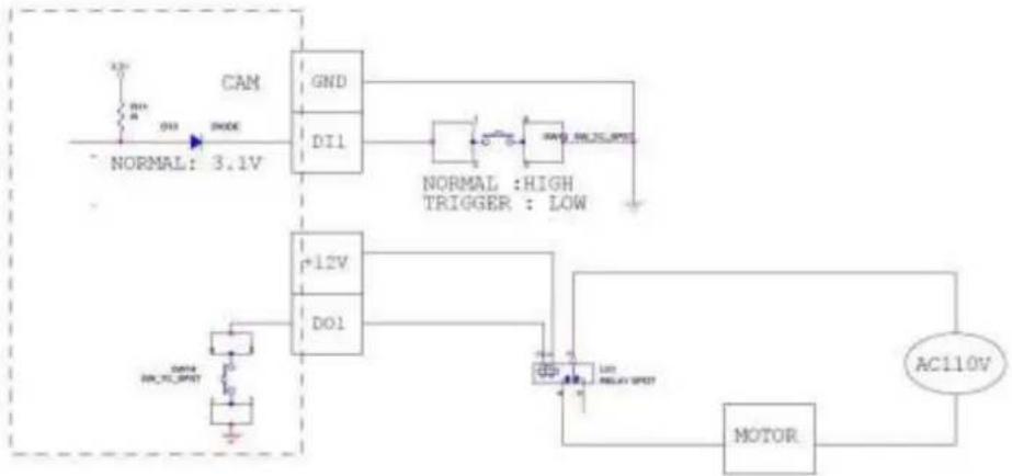
flowchart
graph TD
    A["AC110V"] --> B["MOTOR"]
    B --> C["+12V"]
    C --> D["DI1"]
    D --> E["GND"]
    E --> F["NORMAL: HIGH TRIGGER : LOW"]
    G["NORMAL: 3.1V"] --> H["+12V"]
    H --> I["DI1"]
    I --> J["NORMAL: HIGH TRIGGER : LOW"]
    K["DATA: 40kΩ/div"] --> L["Ground"]
Note that when choosing an appropriate relay, please refer to its specifications and make sure they match the above design. The triggering circuit voltage has to be around 12V DC and the switch-controlled circuit voltage has to match the external power supply (e.g. 110V AC or 220V AC).
The illustration below is a graphic example of connecting a relay to a high voltage DO device.

text_image
CAMERA CPC1018 Relay (DO1 Device) 110V-220V AC External Power Source Camera IlluminatorNOTE: For more information on DI/DO connections, please refer to the Knowledge Base article All About Digital Input and Digital Output downloadable from the link below (http://Download.acti.com?id=516).
Installation Procedures
There are several mounting options that you can use to install the camera. Select the most suitable solution for your installation environment.
Mounting Solutions
| Mount Types | Accessories | |
| Surface Mount | Suitable when mounting the camera on hard or dropped ceilings. The surface mount comes bundled with the camera package. SeeUsing the Bundled Surface Mounton page 20 for mounting instructions. | |
| Flush Mount | Suitable when mounting the camera discretely above dropped ceilings wherein only the dome cover will be visible underneath the ceiling. SeeUsing the Flush Mounton page 23 for mounting instructions. | |
PMAX-1010 | ||
| Pendant Mount | Suitable when mounting the camera on hard and high ceilings. | |
PMAX-0110   | PMAX-0103 (Straight Tube with Bracket) | |
PMAX-0110   | PMAX-0102 (Straight Tube) | |
| Straight Wall Mount | Suitable when mounting the camera on straight walls. | |
PMAX-0311 (L-Type Wall Mount)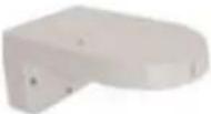 | ||
| Straight Wall Mount | PMAX-0110 | PMAX-0303 (Gooseneck)  | |
| Vertical Pole Mount | Suitable when mounting the camera on vertical poles. | ||
PMAX-0110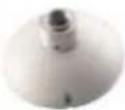 | PMAX-0303 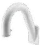 | PMAX-0503[WBYH]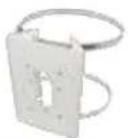 | |
| Horizontal Pole Mount | Suitable when mounting the camera on horizontal poles. | ||
PMAX-0110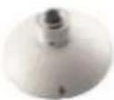 | PMAX-0102 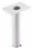 | PMAX-0503 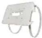 | |
| Corner Mount | Suitable when mounting the camera on a corner wall. | ||
PMAX-0110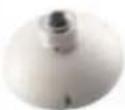 | PMAX-0303  | PMAX-0402 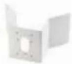 | |
Other Mounting Accessories
| Accessories | |
| PMAX-0702 (Junction Box) | PMAX-0104 (Extension Tubes) |
 | [36WBS] |
NOTE:
- For more information about the mounting solutions and accessories, please check the Mounting Accessory Selector in our website (http://www.acti.com/mountingselector).
- Except for the Surface Mount, the above mounting accessories are not included in the package. Contact your sales agents to purchase.
Mounting on the Ceiling
There are three mounting solutions that you can do to mount the camera on the ceiling:
- Surface Mount: To install the camera directly on the ceiling. Accessories come bundled with the camera package. See below for mounting instructions.
- Flush Mount: To install the camera above the ceiling wherein only the dome cover will be visible from view. See Using the Flush Mount on page 23 for mounting instructions.
- Pendant Mount: To install the camera on high ceilings and the camera will be lowered by the pendant mount. See Using the Pendant Mount on page 29 for mounting instructions.
Using the Bundled Surface Mount
The camera package comes with a surface mount kit which allows the camera to be directly installed onto a hard ceiling.
-
Using the mount drill template, mark the screw holes on the ceiling, then drill the holes and insert the supplied plastic plugs.
-
Push at the marked points below to detach the cover ring from the metal plate.
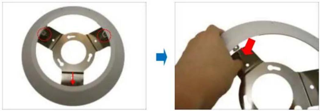
natural_image
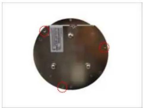
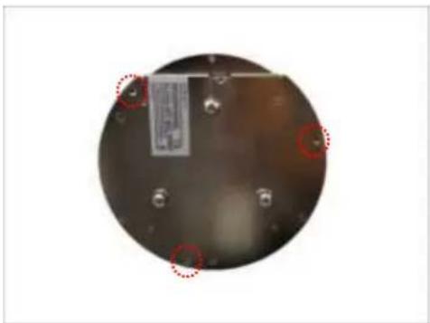
Two-step diagram showing a mechanical component before and after assembly, with arrows indicating features (no text or symbols present)- Attach the metal plate to the ceiling using the three (3) supplied screws.

natural_image
Metal three-pronged bracket component with mounting holes and red circular markings (no text or symbols)- Align and attach the fixing bracket to one of the holes on the camera using the supplied screw (holes marked below). The fixing bracket will fix the camera position when mounted later.
natural_image
Circular metallic object with embedded metal components and red-circled highlights (no visible text or symbols)
natural_image
Close-up of a hand holding a small electronic component, showing a close-up view of a device with a metallic housing and a cable being inserted (no text or symbols visible)- Align and insert the camera base hooks to the mounting holes of the metal plate.
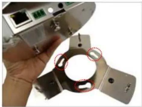
natural_image
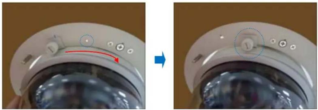
Close-up of a hand holding a metal mechanical component with red dotted circles highlighting features (no text or symbols visible)- Slide the camera clockwise to secure the hooks to the mount.
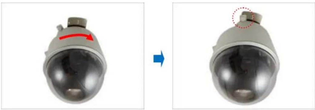
natural_image
Two views of a security camera head showing a red arrow indicating rotation and a dotted circle highlighting the lens (no text or symbols present)- Tighten the screw on the fixing bracket to fix the camera position. This is to avoid accidental camera movement as the camera performs PTZ functions.

natural_image
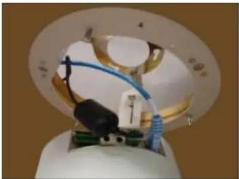
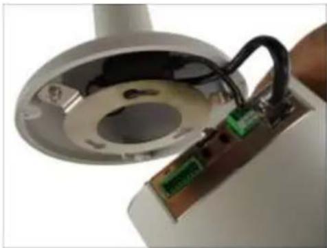
Close-up of a hand holding a small object, with an inset close-up showing a mechanical component (no text or symbols visible)- Connect the network cable, power adapter and any other cable connections (such as DI/DO, audio in, etc.) to the camera.
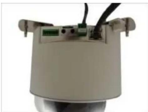
natural_image
Close-up of a mechanical sensor or camera module with visible wiring and ports (no text or symbols)NOTE: The cables may be routed along the ceiling if the camera is installed on a hard ceiling. Or, the cables may pass through a hole on the ceiling if the camera is installed on a dropped ceiling.
-
Remove the pre-cut tab on the cover ring using pliers.
-
Note that the cables will pass through the cut, align the metal plate hooks onto the holes of the cover ring and then push to secure it in place. Final installation would look similar to the picture below.
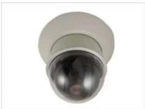
natural_image
Close-up of a metallic cylindrical sensor or camera lens with a spherical dome and reflective surface (no text or symbols visible)Using the Flush Mount
Use the Flush Mount when installing the camera on a dropped ceiling; there is space above the ceiling where the camera body can be hidden from view and only the dome cover can be seen underneath the ceiling.
NOTE: The Flush Mount is not included in the camera package. Contact your sales agents to purchase.
Before installation, prepare the following:
| Flush Mount Kit | Other Tools (not supplied) |
| Flush MountDrill templateScrew (1)Foam rubber pads (3)Fixing bracket | Jig sawPhillips screwdriver |
To mount the camera, follow the procedures below:
Step 1: Drill a Hole on the Ceiling
Drill a 184-mm diameter hole on the ceiling where you want to mount the camera, then route the network cable, power adapter, and other cables (e.g. DI/DO, audio cables, etc.) through the hole.

natural_image
Circular device with attached wires and connectors, no visible text or symbolsStep 2: Prepare the Flush Mount
- Push to detach the cover ring from the mount as marked below. Then set the cover ring aside.

natural_image
Mechanical component assembly showing a circular component before and after disassembly (no text or symbols visible)- Peel off the lining of the three (3) foam rubber pads and attach a rubber pad to each retaining bracket.
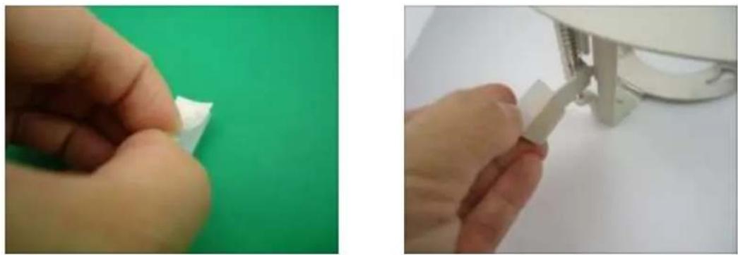
natural_image
Two-panel image showing hands assembling or adjusting a white plastic component on a green surface, with no visible text or symbols.Step 3: Loosen the Retaining Brackets
Using a screwdriver, loosen the retaining brackets according to the thickness of the ceiling.

natural_image
Close-up of a hand using a tool to cut or inspect a mechanical component against a green background (no text or symbols visible)Step 4: Install the Mount
- Insert the metal bracket through the hole until the ring edge is flat on the ceiling.

natural_image
Close-up of hands installing or adjusting a circular component with a blue cable, no visible text or symbols- Position the retaining brackets to hold the mount on the ceiling.
natural_image
Hand using a tool to install a ceiling light fixture (no text or symbols visible)NOTE: The following illustration shows how the flush mount will look like when viewed from inside the ceiling. In case you cannot access inside the ceiling, use your fingers to position the retaining brackets through the hole.

natural_image
Close-up of a circular mechanical component with red directional arrows indicating rotation or movement (no text or symbols)- Tighten the screws to secure the mount and make sure the network cable, power adapter, and other cables (if necessary) are routed on the outer gap of the metal bracket.

natural_image
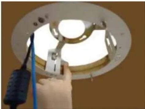
Interior view of a ceiling lamp with exposed light and wiring, no text or symbols visible- Attach the fixing bracket to one of the holes on the camera using the supplied screw (holes marked below). The fixing bracket will fix the camera position when mounted later.
natural_image
Circular metallic object with red circles highlighting features, no visible text or symbols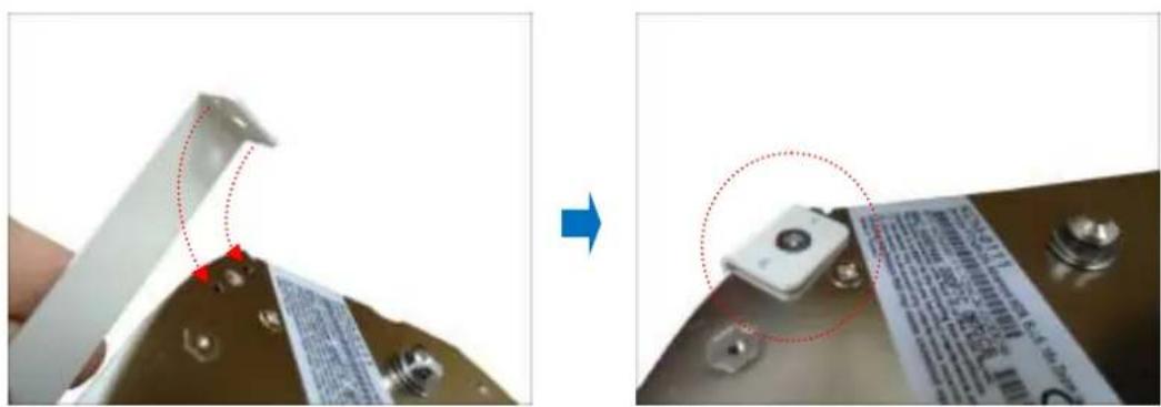
natural_image
Close-up of a device component being held, showing a close-up of a small electronic component with a red dotted line indicating alignment (no text or symbols visible)Step 5: Connect the Cables and Optional Accessories
- Insert a memory card into the camera card slot (if necessary).
- Connect the network cable, power adapter, and other cables, such as DI/DO, etc. (if any) to the camera.
natural_image
Close-up of a medical or laboratory device with transparent glass and blue tubing, no visible text or symbolsStep 6: Install the Camera
- Align the camera base hooks to the holes on the bracket and then insert the camera through the bracket.

natural_image
Close-up of a mechanical assembly with circular components and blue cables, no visible text or symbolsNOTE:
- Take note that the network cable must be bent to insert the camera into the mount. If the network cable you are using is not flexible or too rough to be bent, it is recommended to use the bundled network extension cable (included in the camera package). The bundled network extension cable is flexible enough to be bent and makes it easy to insert the camera through the mount.
-
Or, if you can access the inside of the ceiling, you may mount the camera first and then connect the cables.
-
Slide the camera clockwise to secure the hooks to the mount. Notice that the fixing bracket screw becomes aligned with the hole on the metal bracket
natural_image
Close-up of a kitchen appliance showing a dial indicator and control buttons, before and after transformation (no text or symbols visible)- Tighten the screw on the fixing bracket to fix the camera position. This is to avoid accidental camera movement as the camera performs PTZ functions.

natural_image
Close-up of a hand holding a small mechanical component, possibly a knob or dial, with no visible text or symbols.Step 7: Attach the Cover Ring
- Align the metal latches and the latches on the cover ring.
natural_image
Close-up of hands holding a white appliance with a lid, showing internal contents (no visible text or symbols)- Push to firmly secure the cover ring latches.
Using the Pendant Mount
In case of high ceilings, the camera can be lowered by pendant mount.
NOTE: The Pendant Mount is not included in the camera package. Contact your sales agents to purchase.
Prepare the following:
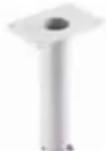
- Pendant Mount Kits (PMAX-0110 and either PMAX-0103 or PMAX-0102)
PMAX-0110

PMAX-0103
(Straight Tube with Bracket)

Use this configuration if the cable cannot directly enter the ceiling and must go along the ceiling.
or
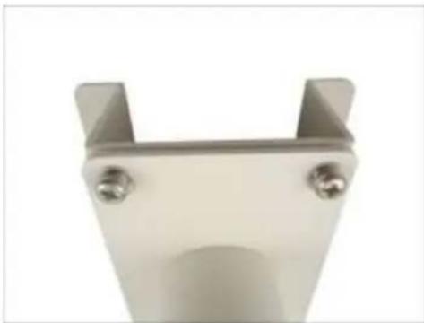
PMAX-0102 (Straight Tube without Bracket)
Use this configuration if the cable can directly enter the ceiling.
- Mounting Screws (included in the mount kit package)
• Network Extension Cable (included in the PMAX-0110 kit) - Screwdriver (not included)
Step 1: Install the Straight Tube
- Use the drill template (included in the straight tube package) to mark and drill the mounting holes on the ceiling.
- Insert the power adapter, network cable, and other necessary cables (if any) to pass through the straight tube. Note that you must insert the power adapter cable first to fit the tube.
NOTE:
- If using a straight tube without bracket, route the cables to pass through the hole on the ceiling.
- The following illustrations show the installation using a straight tube with bracket.

natural_image
Close-up of a small electronic component with a green sensor mounted on a transparent base, connected by wires (no visible text or symbols)- Install the straight tube on the ceiling.
natural_image
Close-up of a metallic U-shaped metal bracket with two screws and a central cylindrical component (no text or symbols visible)NOTE: If the straight tube is not long enough, you may use one or more extension tubes (purchased separately).
Step 2: Install the Mount Kit (PMAX-0110)
- Insert the cables from the tube into the mount kit and route them to pass through the outer bracket.

natural_image
Close-up of a device component with wiring and a magnified view showing internal wiring (no text or symbols)- Align the slot of the mount kit to the tab inside the straight tube and install the mount kit.

natural_image
Close-up of a hand holding a white cylindrical device with a red circular annotation highlighting a small component (no text or symbols visible)- Twist the mount kit to align the screw holes and attach the two (2) mounting screws (included in the mount kit package).

natural_image
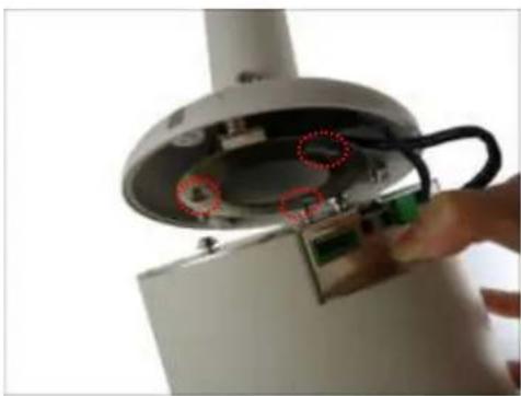
Two-step photo showing a white dome-shaped object before and after modification, with red arrows indicating direction and red circles highlighting features (no text or symbols)Step 3: Install the Camera
- Connect the network cable to the Ethernet port of the camera. If necessary, connect the other cables (such as power adapter, DI/DO, etc.) to the corresponding connectors.
natural_image
Close-up of a device's internal components, including a circular base with internal circuitry and a green electronic component inserted into a housing (no visible text or symbols)NOTE: Try to push the network cable further into the mount.
TIP: If the network cable texture is rough and not easily bent, use the bundled network extension cable (included in the mount kit package) to easily route the cables because of its flexibility.
- Align and insert the camera base hooks to the mounting holes.
natural_image
Close-up of a hand inserting a device into a cylindrical device with a cable (no visible text or symbols)- Slide the camera counter-clockwise to secure the hooks to the mount.

natural_image
Close-up of a white cylindrical device with internal components and a red arrow indicating direction (no text or symbols)- On the top of the mount kit, attach three (3) screws (included in the mount kit package) to secure the camera to the mount.

natural_image
Close-up of a red-handled tool tip touching a white circular component, with two red circles highlighting the points of interest (no text or symbols present)The final installation would look similar to the one below:
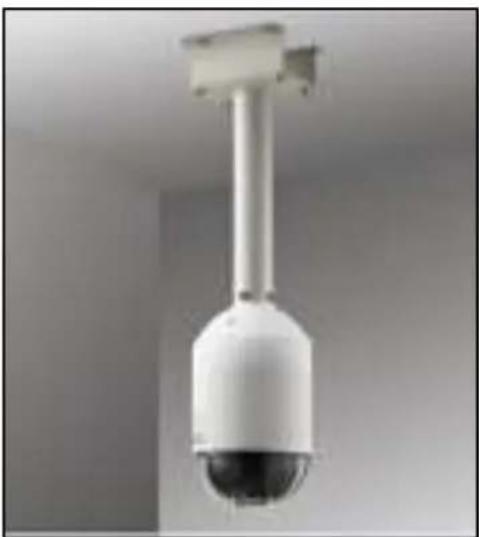
natural_image
Close-up of a white security camera with a spherical dome and mounted sensor array (no text or symbols visible)Mounting on Straight Wall
There are four (4) mounting solutions that you can do to mount the camera on the straight wall. The L-Type Wall Mount is used to install the camera facing down as if it is installed on a ceiling (see below for mounting instructions). Other straight wall mounting solutions, such as the Gooseneck allow the camera to be installed further away from the wall. Cables may be routed through the wall or along the wall. Select the solution that is most applicable to your installation requirements.
Using the L-Type Wall Mount
To install the camera on a straight wall, use the L-Type Wall Mount. The camera will be facing down as if installed on a ceiling.
NOTE: The L-Type Wall Mount is not included in the camera package. Contact your sales agents to purchase.
Before installation, prepare the following:
| L-Type Wall Mount Package | Other Tools (not supplied) |
| • L-Type Wall Mount• Drill template• Screws (3) | • Phillips screwdriver |
Step 1: Install the L-Type Wall Mount
- Use the drill template (included in the L-type wall mount package) to mark and drill the mounting holes on the wall.
Route the cable(s).
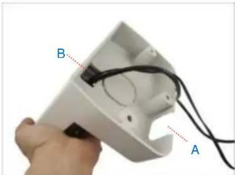
2a. If the cable(s) will pass through the wall, insert the cable(s) through the cable hole as marked below (A).
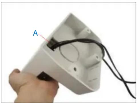
natural_image
Hand holding a white electronic device with black wires and labeled component 'A' (no text or symbols on the device itself)2b. If the cable will go along the wall, remove the pre-cut tab on the L-type wall mount using pliers. Then route the cable through the cable holes (A to B) as marked below.
natural_image
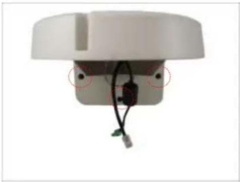
Close-up of a hand holding a white electronic device with labeled points A and B, showing internal wiring (no text or symbols beyond labels)With the cable(s) dangling, attach three (3) screws (included in the camera package) to install the L-type wall mount onto the wall.
natural_image
Close-up of a white electronic device with wires and connectors, no visible text or symbolsStep 2: Install the Camera
- Connect the network cable to the Ethernet port of the camera. If necessary, connect the other cables (such as power adapter, DI/DO, etc.) to the corresponding connectors.

natural_image
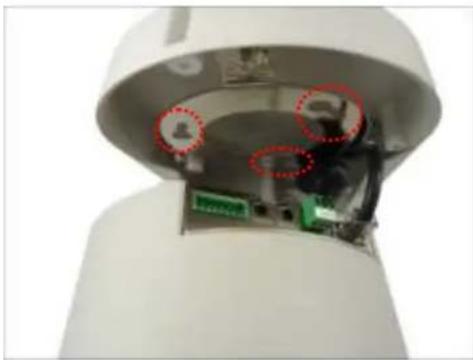
Interior view of a white cylindrical device showing internal components and a green circuit board (no text or symbols visible)- Align and insert the camera base hooks to the mounting holes.
natural_image
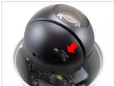
Interior view of a white cylindrical device with internal components and red dotted circles highlighting areas (no text or symbols visible)- Slide the camera clockwise to secure the hooks to the mount.

natural_image
Close-up of a security camera with a red arrow pointing to the side panel (no text or symbols visible)- Attach three (3) screws (included in the L-type wall mount package) to secure the camera to the mount.

natural_image
3D rendered mechanical component with a red screwdriver and two red circular annotations (no text or symbols)Other Accessories and Adjustments
How to Install / Remove the Memory Card
NOTE: Supports microSDHC and microSDXC cards.
B913, B923, B934
- Rotate the dome cover counter-clockwise to remove it.

natural_image
Hand holding a dome-shaped security camera with a red curved arrow indicating motion (no text or symbols visible)- Insert the memory card into the card slot near the camera shot.
natural_image
Close-up of a black dome-shaped device with a red arrow pointing to a small component, no visible text or symbols.-
Push the card completely until it clicks into place.
-
Rotate the dome cover clockwise to attach it.
I91, I92, I912
- Insert the memory card with the metal contacts facing down the camera lens.

natural_image
Close-up of a metallic electronic device showing internal components with green connectors and a red arrow pointing to a component (no visible text or symbols)- Push the card completely until it clicks into place.
How to Remove the Memory Card
In case there is a need to remove the card, make sure to access the camera Web Configurator to safely "unmount" the card first (see the camera Firmware User's Manual for more information). Once unmounted from the firmware, push the card to eject it from the slot.
How to Replace the Dome Cover
Depending on your surveillance needs, you may want to replace the bundled dome cover with a smoke dome cover available for purchase.
To replace the dome cover, do the following:
- Rotate the dome cover counter-clockwise to remove it.

natural_image
Two-step photo showing a hand holding a camera module, with a red curved arrow indicating motion (no text or symbols)- Rotate the replacement dome cover clockwise to attach it.

natural_image
Hand pressing a black dome-shaped object with a red curved arrow on its surface (no text or symbols visible)How to Reset the Camera
A reset may be necessary if the following instances happen:
- The administrator's password has been forgotten and therefore the camera cannot be accessed.
- In case of IP address, mask, or allow/deny filter related issues, resulting with inability to modify these settings.
- In case of connectivity issues or abnormal video quality.
With the camera powered on, use a pointed object, such as a pen, to press and hold the reset button for at least 5 seconds or until the Power LED goes off.
Accessing Camera
Configure the IP Addresses
In order to be able to communicate with the camera from your PC, both the camera and the PC have to be within the same network segment. In most cases, it means that they both should have very similar IP addresses, where only the last number of the IP address is different from each other. There are 2 different approaches to IP Address management in Local Area Networks – by DHCP Server or Manually.
Using DHCP server to assign IP addresses
If you have connected the computer and the camera into the network that has a DHCP server running, then you do not need to configure the IP addresses at all – both the camera and the PC would request a unique IP address from the DHCP server automatically. In such case, the camera will immediately be ready for the access from the PC. The user, however, might not know the IP address of the camera yet. It is necessary to know the IP address of the camera in order to access it using a Web browser.
The quickest way to discover the cameras in the network is to use the simplest network search, built in the Windows system – just by pressing the “Network” icon, all the cameras of the local area network will be discovered by Windows, thanks to the UPnP function support of our cameras.
In the example below, the camera that has just been connected to the network is successfully found.
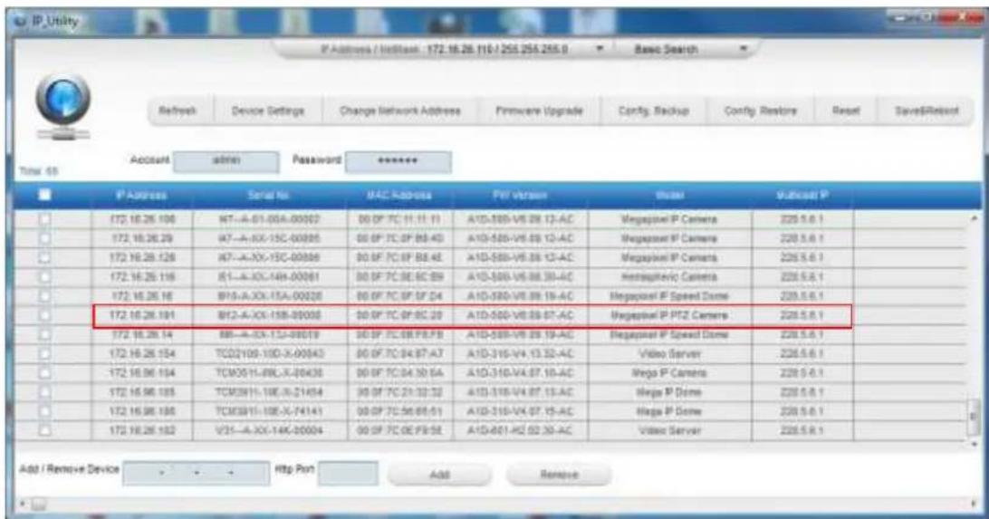
text_image
IP Address / WebBank: 172.16.28.110/255.255.255.0 Basic Search Refresh Device Settings Change Network Address Firmware Upgrade Config Backup Config Restore Reset Save&Reset Access admin Password ****** Time: 09 IP Address Serial No MAC Address PET Version Status Multicell P 172.16.26.100 WT-A-01-00A-00002 00 PF 7C 11:11:11 A1D-585-V6.08.13-AC Megaport IP Camera 228.5.6.1 172.16.26.29 WT-A-XX-15C-00005 00 PF 7C 0F BB-4D A1D-585-V6.09.12-AC Megaport IP Camera 228.5.6.1 172.16.26.128 WT-A-XX-15C-00006 00 BF 7C 0F BB-4E A1D-585-V6.08.13-AC Megaport IP Camera 228.5.6.1 172.16.26.116 01-A-XX-14A-00061 00 BF 7C 0E BC-89 A1D-585-V6.08.30-AC Hemispheric Camera 228.5.6.1 172.16.26.16 BFS-A-XX-15A-00028 00 BF 7C 0F SF D4 A1D-585-V6.09.19-AC Megaport IP Speed Dome 228.5.6.1 172.16.26.191 BFI-A-XX-15B-00003 00 BF 7C 0F BC-29 A1D-585-V6.09.07-AC Megaport IP PTZ Camera 228.5.6.1 172.16.26.14 BB-A-XX-13J-09019 00 BF 7C 0B PB-FB A1D-589-V6.09.19-AC Megaport IP Speed Dome 228.5.6.1 172.16.26.154 TCOI/O9-10D-X-90043 00 BF 7C 04:87-A7 A1D-315-V4.13.32-AC Video Server 228.5.6.1 172.16.96.194 TCMOS/IL-BRL-X-09435 00 BF 7C 04:30-5A A1D-315-V4.07.19-AC Mega IP Camera 228.5.6.1 172.16.96.185 TCMOS/IL-18E-X-21454 00 BF 7C 21:33:32 A1D-315-V4.07.13-AC Mega IP Dome 228.5.6.1 172.16.96.188 TCMOS/IL-18E-X-74141 00 BF 7C 56:68:51 A1D-315-V4.07.15-AC Mega IP Dome 228.5.6.1 172.16.26.192 VZI-A-XX-14K-00004 00 BF 7C 0E PB-SE A1D-401-HZ 62:39-AC Video Server 228.5.6.1 Add / Remove Device Http Port Add RemoveWhen the left mouse is clicked on the camera model name, the default browser of the PC is automatically launched and the IP address of the target camera is already filled in the address bar of the browser.
If you work with our cameras regularly, then there is even a better way to discover the cameras in the network – by using IP Utility. The IP Utility is a light software tool that can not only discover the cameras, but also list lots of valuable information, such as IP and MAC addresses, serial numbers, firmware versions, etc, and allows quick configuration of multiple devices at the same time.
Download IP Utility for free from http://www.acti.com/product/IP%20Utility%204.
When you launch IP Utility, the list of connected cameras in the network will be shown. See sample illustration below:
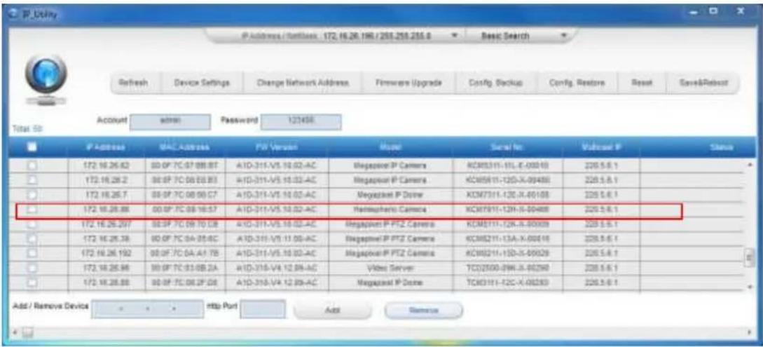
text_image
IP Address / Settless 172.16.28.196/258.258.255.0 Refresh Device Settings Change Network Address Firmware Upgrade Config. Backup Config. Restore Reset Save&Reboot Account admin Password 123458 IP Address MAC Address FV Version Model Serial No Multiseal P Status 172.16.26.62 00:0F:7C:07:08:8T A1D-311-V5.10.02-AC Megapanel P Camera KCM3311-15L-X-00010 226.5.6.1 172.16.26.2 00:0F:7C:08:08:83 A1D-311-V5.10.02-AC Megapanel P Camera KCM5811-12D-X-00488 226.5.6.1 172.16.26.7 00:0F:7C:08:08:67 A1D-311-V5.10.02-AC Megapanel P Driver KCM7311-12C-X-00108 226.5.6.1 172.16.26.88 00:0F:7C:08:16:57 A1D-311-V5.10.02-AC Hemsapherio Camera KCM7911-12H-X-00488 226.5.6.1 172.16.26.297 00:0F:7C:08:70:08 A1D-311-V5.10.02-AC Megapanel P PTZ Camera KCM8111-12K-X-00009 226.5.6.1 172.16.26.38 00:0F:7C:0A:05:4C A1D-311-V5.11:08-AC Megapanel P PTZ Camera KCM8211-13A-X-00616 226.5.6.1 172.16.26.192 00:0F:7C:0A:A4:7B A1D-311-V5.10.02-AC Megapanel P PTZ Camera KCM9211-13D-X-00029 226.5.6.1 172.16.26.98 00:0F:7C:03:0B:2A A1D-318-V4.12:09-AC Video Server TCJ2500-29W-X-00298 226.5.6.1 172.16.26.88 00:0F:7C:08:2F:08 A1D-318-V4.12:09-AC Megapanel P Driver TCX3111-12C-X-00283 226.5.6.1 Add / Remove Device http Port Add RemoveYou can quickly notice the camera model in the list. Click on the IP address to automatically launch the default browser of the PC with the IP address of the target camera already filled in the address bar of the browser.
Use the default IP address of the camera
If there is no DHCP server in the given network, the user may have to manually assign the IP addresses to both the PC and the camera to make sure they are in the same network segment.
When the camera is plugged into the network and it does not detect any DHCP services, it will automatically assign itself a default IP:
192.168.0.100
Whereas the default port number would be 80. In order to access that camera, the IP address of the PC has to be configured to match the network segment of the camera.
Manually adjust the IP address of the PC
In the following example, based on Windows 7, we will configure the IP address to
192.168.0.99 and set Subnet Mask to 255.255.255.0 by using the steps below:
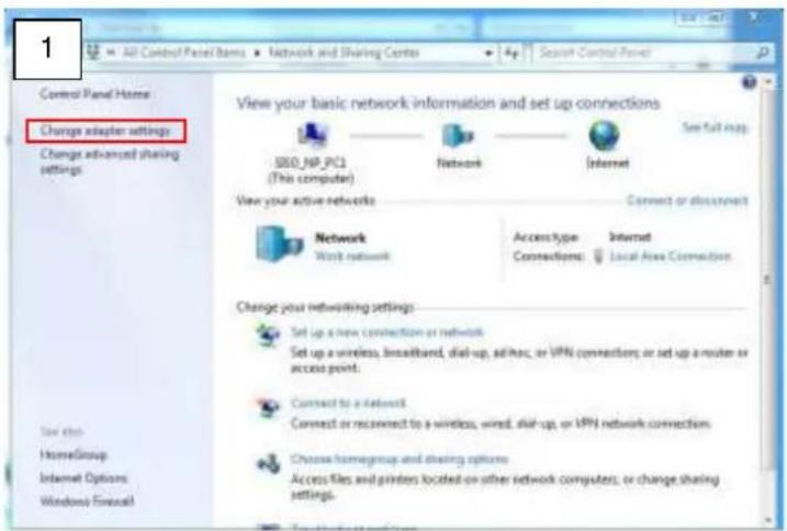
text_image
1 All Control Panel Items ▶ Network and Sharing Center ▶ 4p Select Control Panel Control Panel Home Change adapter settings Change advanced sharing settings View your basic network information and set up connections SBB_NP_PC1 (This computer) Network Internet Set full map View your active networks Connect or disconnect Network Work network Access Type Connections: Internet Local Area Connection Change your networking settings Set up a new connection or network Set up a wireless, broadband, dial-up, address, or VPN connections; or set up a router or access point. Connect to a network Connect or reconnect to a wireless, wind, dial-up, or VPN network connections. Choose homegroup and sharing options Access files and printers located on other network computers; or change sharing settings.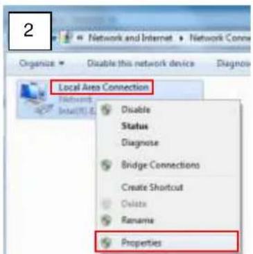
text_image
2 Network and Internet Organize Disable this network device Diagnosis Local Area Connection Network Install/RE Disable Status Diagnose Bridge Connections Create Shortcut Delete Rename Properties
text_image
Connect using Intel(R) 82567LM-3 Gigabit Network Connection Configure... This connection uses the following items: Client for Microsoft Networks VirtualBox Bedged Networking Driver GoS Packet Scheduler File and Printer Sharing for Microsoft Networks Internet Protocol Version 6 (TCP/IPvB) Remote Protocol/Internet Interface Link-Layer Topology Discovery Mapper I/O Driver Link-Layer Topology Discovery Responder Install Uninstall Properties Description Transmission Control Protocol/Internet Protocol. The default wide area network protocol that provides communication across diverse interconnected networks. OK Cancel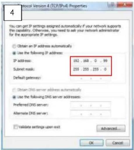
text_image
4 You can get IP settings assigned automatically if your network supports this capability. Otherwise, you need to ask your network administrator for the appropriate IP settings. Obtain an IP address automatically Use the following IP address: IP address: 192 , 168 , 0 , 99 Subnet mask: 255 , 255 , 255 , 0 Default gateway: Obtain DNS server address automatically Use the following DNS server addresses: Preferred DNS server: Alternate DNS server: Validate settings upon exit Advanced... OK CancelManually adjust the IP addresses of multiple cameras
If there are more than one camera to be used in the same local area network and there is no DHCP server to assign unique IP addresses to each of them, all of the cameras would then have the initial IP address of 192.168.0.100, which is not a proper situation for network devices – all the IP addresses have to be different from each other. The easiest way to assign cameras the IP addresses is by using IP Utility:
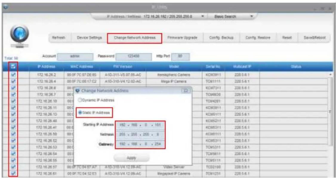
text_image
IP Address / Settings: 172.16.25.182 / 205.255.230.0 Refresh Device Settings Change Network Address Firmware Upgrade Config. Backup Config. Restore Reset Save&Reboot Total 56 Account admin Password 123458 Http Port 30 IP Address MAC Address FW Version Model Serial No Multicast IP Status 172.16.26.2 00.0F-7C:97:DE:85 A1D-311-V5.07:05-AC Hemispheric Camera KCM3911 220.5.6.1 172.16.26.4 00.0F-7C:00:17:02 A1D-310-V4.12:02-AC Mega IP Camera TOM1111 220.5.6.1 172.16.26.8 00.0F Change Network Address Dynamic IP Address Static IP Address Starting IP Address 192 - 188 - 8 - 101 Netmask 255 - 255 - 255 - 8 Gateway 192 - 188 - 8 - 254 Apply 172.16.26.57 00.0F-7C:94:87:A7 A1D-310-V4.12:09-AC Video Server TCD2190 230.5.6.1 172.16.26.61 00.0F-7C:94:32:E3 A1D-310-V4.12:09-AC Regepilot IP Camera TOM1231 220.5.6.1With the procedure shown above, all the cameras will have unique IP addresses, starting from 192.168.0.101. In case there are 20 cameras selected, the last one of the cameras would have the IP 192.168.0.120.
Later, by pressing the "Refresh" button of the IP Utility, you will be able to see the list of cameras with their new IP addresses.
Please note that it is also possible to change the IP addresses manually by using the Web browser. In such case, please plug in only one camera at a time, and change its IP address by using the Web browser before plugging in the next one. This way, the Web browser will not be confused about two devices having the same IP address at the same time.
Access the Camera
Now that the camera and the PC both have their unique IP addresses and are under the same network segment, you can use Microsoft Internet Explorer on the PC to access the camera.
You can use Microsoft Internet Explorer to access the camera.
When using Internet Explorer browser, the ActiveX control for video stream management will be downloaded from the camera directly – the user just has to accept the use of such control when prompted so. No other third party utilities are required to be installed in such case.
The examples in this manual are based on Internet Explorer browser in order to cover all functions of the camera.
Assuming that the camera's IP address is 192.168.0.100, you can access it by opening the Web browser and typing the following address into Web browser's address bar:
http://192.168.0.100
Upon successful connection to the camera, the user interface called Web Configurator would appear together with the login page. The HTTP port number was not added behind the IP address since the default HTTP port of the camera is 80, which can be omitted from the address for convenience.

text_image
http://192.168.0.100 Web Configurator Web Configurator Login Account Password Language English Login ResetBefore logging in, you need to know the factory default Account and Password of the camera.
Account: Admin
Password: 123456
For further operations, please refer to the Firmware User's Manual.

ACTi
Connecting Vision
Copyright © 2018, ACTi Corporation All Rights Reserved
7F, No. 1, Alley 20, Lane 407, Sec. 2, Ti-Ding Blvd., Neihu District, Taipei, Taiwan 114, R.O.C.
TEL: +886-2-2656-2588 FAX: +886-2-2656-2599
Email: sales@acti.com