SMAX-0052 - Security Camera ACTi - Free user manual and instructions
Find the device manual for free SMAX-0052 ACTi in PDF.

User questions about SMAX-0052 ACTi
0 question about this device. Answer the ones you know or ask your own.
Ask a new question about this device
Download the instructions for your Security Camera in PDF format for free! Find your manual SMAX-0052 - ACTi and take your electronic device back in hand. On this page are published all the documents necessary for the use of your device. SMAX-0052 by ACTi.
USER MANUAL SMAX-0052 ACTi
natural_image
Abstract geometric design with a red vertical bar and a gray star-like shape (no text or symbols)Indoor PTZ
Mounting on the Ceiling
Table of Contents
Installation Procedures 3
Step 1: Install the Straight Tube .... 4
Step 2: Install the Mount Kit (PMAX-0110)....5
Step 3: Install the Camera....6
Step 4: Access the Camera Live View....7
Safety Information......8
Installation Procedures
In case of high ceilings, the camera can be lowered by pendant mount.
| Mounting Solution | Cabling Solution | Must Drill a Hole on the Ceiling |
| Straight Tube(SMAX-0052) | Use this configuration if the cable can directly enter the ceiling. | Yes |
PMAX-0102  | PMAX-0110[2HX6] | |
| Straight Tube with Bracket(SMAX-0053) | Use this configuration if the cable cannot directly enter the ceiling and must go along the ceiling. | No |
PMAX-0103  | PMAX-0110  |
Step 1: Install the Straight Tube
- Use the drill template (included in the straight tube package) to mark and drill the mounting holes on the ceiling.
- Insert the power adaptor, network cable, and other necessary cables (if any) to pass through the straight tube. Note that you must insert the power adaptor cable first to fit the tube.
NOTE:
- If using a straight tube without bracket, route the cables to pass through the hole on the ceiling.
• The following illustrations show the installation using a straight tube with bracket.
natural_image
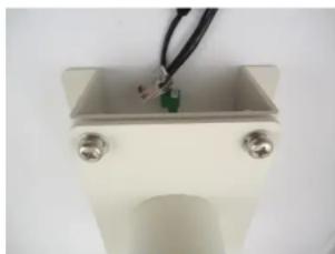
Close-up of a small electronic component with a green sensor and black wires, mounted on a white base (no visible text or symbols)- Install the straight tube on the ceiling.
Step 2: Install the Mount Kit (PMAX-0110)
- Insert the cables from the tube into the mount kit and route them to pass through the outer bracket.
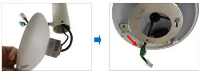
natural_image
Close-up of a device with cable and wiring, showing internal components before and after assembly (no text or symbols visible)- Align the slot of the mount kit to the tab inside the straight tube and install the mount kit.
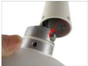
natural_image
Close-up of a white cylindrical device with a red highlighted section, possibly part of a mechanical or electronic component (no visible text or symbols)Step 3: Install the Camera
- If necessary, insert a memory card into the card slot of the camera.
- Connect the network cable to the Ethernet port of the camera. If necessary, connect the other cables (such as power adaptor, DI/DO, etc.) to the corresponding connectors.

natural_image
Close-up of a mechanical component with exposed internal structure and wiring (no visible text or symbols)NOTE: Try to push the network cable further into the mount.
TIP: If the network cable texture is rough and not easily bent, use the bundled network extension cable (included in the mount kit package) to easily route the cables because of its flexibility.
- Align and insert the camera base hooks to the mounting holes.
Installation Guide

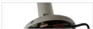
- On the top of the mount kit, attach three (3) screws (included in the mount kit package) to secure the camera to the mount.

natural_image
Close-up of a red screwdriver inserted into a white circular component with a small hole, no visible text or symbols.The final installation would look similar to the one below:
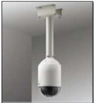
natural_image
Close-up of a white surveillance camera with a spherical lens mounted on a vertical pole against a plain wall (no text or symbols visible)Safety Information
Read these instructions
You should read all the safety and operating instructions before using this product.
Heed all warnings
You must adhere to all the warnings on the product and in the instruction manual. Failure to follow the safety instruction given may directly endanger people, cause damage to the system or to other equipment.
Trademarks
All names used in this manual are probably registered trademarks of respective companies.
Liability
Every reasonable care has been taken during the writing of this manual. Please inform your local office if you find any inaccuracies or omissions. We cannot be held responsible for any typographical or technical errors and reserve the right to make changes to the product and manuals without prior notice.
Cleaning
Disconnect this video product from the power supply before cleaning.
A
Damage Requiring service
Disconnect this video product from the power supply immediately and refer servicing to qualified service personnel under the following conditions.
1) When the power-supply cord or plug is damaged
2) If liquid has been spilled, or objects have fallen into the video product.
3) If the inner parts of video product have been directly exposed to rain or water.
4) If the video product does not operate normally by following the operating Instructions in this manual. Adjust only those controls that are covered by the instruction manual, as an improper adjustment of other controls may result in damage, and will often require extensive work by a qualified technician to restore the video product to its normal operation.
Safety Check
Upon completion of any service or repairs to this video product, ask the service technician to perform safety checks to determine if the video product is in proper operating condition.