
TH-2050-UFL - Mount Atdec - Free user manual and instructions
Find the device manual for free TH-2050-UFL Atdec in PDF.

| Product Type | TV Articulated Arm |
| Brand | Atdec |
| Model | TH-2050-UFL |
| Maximum Load | 25 kg (55 lbs) |
| VESA Compatibility | 200x100 mm to 400x400 mm |
| Mounting Type | Wall mount (timber stud or solid wall) |
| Arm Type | Articulated double ball mount |
| Tilt Adjustment | Yes, via double ball mount tension plate |
| Roll Adjustment | Yes, via double ball mount tension plate |
| Swivel / Rotation | Yes, via articulated arm |
| Cable Management | Yes, integrated cover |
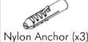
| Included Hardware | Mounting plate, display mounting brackets, locking blocks, top caps, screws, nylon anchors, coach screws |
| Tools Required | Power drill, 4.5 mm drill bit, 10.5 mm masonry drill bit, Phillips screwdriver, 10 mm socket wrench, 13 mm socket wrench |
| Installation Instructions | Yes, included in manual |
| Number of Installers | 2 people recommended for attaching/detaching display |
Frequently Asked Questions - TH-2050-UFL Atdec
User questions about TH-2050-UFL Atdec
0 question about this device. Answer the ones you know or ask your own.
Ask a new question about this device
Download the instructions for your Mount in PDF format for free! Find your manual TH-2050-UFL - Atdec and take your electronic device back in hand. On this page are published all the documents necessary for the use of your device. TH-2050-UFL by Atdec.
USER MANUAL TH-2050-UFL Atdec
Installation Instructions
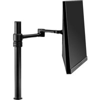
TH-2050-UFL Small-Medium TV Articulated Arm
Component Checklist

Hardware


Tools Required:
- Power drill
• 4.5mm (0.18") drill bit
• 10.5mm (0.41") masonry drill bit
Phillips head screw driver•
• 10mm (0.39") socket wrench or shifter
• 13mm (0.5") socket wrench or shifter
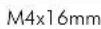
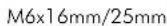
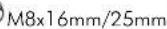
Display Mounting Screws (x4 each)
IMPORTANT INFORMATION:
! IMPORTANT - Install 2050 Small-Medium TV Articulated Arm per Installation Instructions.
! This product supports a maximum load of 25kg (55lbs).
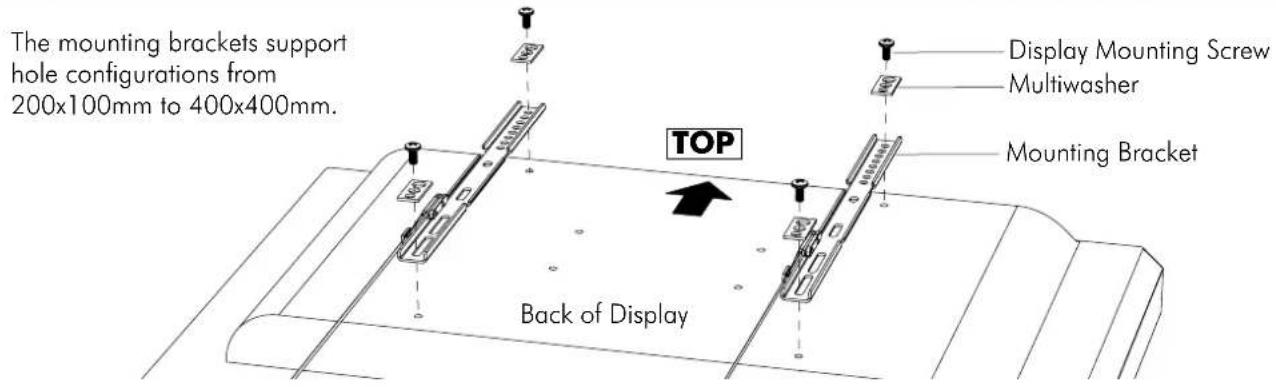
! This product supports VESA mounting hole configurations 200mm wide x100mm high to 400mm wide x 400mm high.
! The manufacturer accepts no responsibility for incorrect installation.
Step 1. Check Components
Check you have received all parts against the Component Checklist and Hardware above.
Step 2. Install Arm/Wall Mount to the Wall
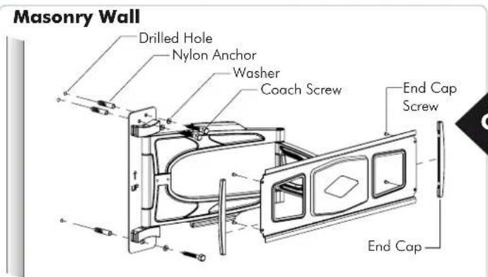
- Drill three 10.5mm (0.41") diameter holes, 58mm (2.3") deep.
- Secure the mounting plate to the wall using the Coach Screws and Nylon Anchors supplied.
Timber Stud Wall

- Drill three 4.5mm (0.18") diameter holes, 58mm (2.3") deep.
- Secure the mounting plate to the wall using the Coach Screws supplied.
NOTE: Use a stud finder to accurately locate the centre of the stud. Ensure that all screws fix securely into stud.
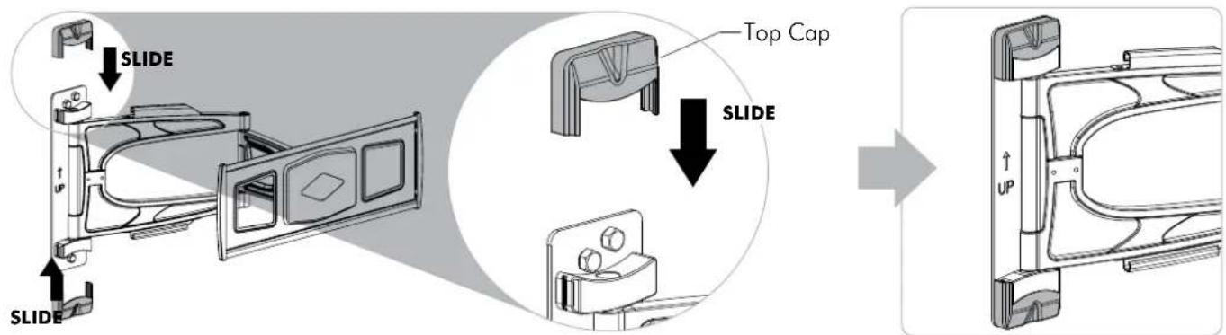
Step 3. Attach Top Caps to the installed Arm/Wall Mount
Step 4. Attaching Mounting Brackets to Display
Step 5. Attaching/Detaching Display to the installed Arm (2 people required)
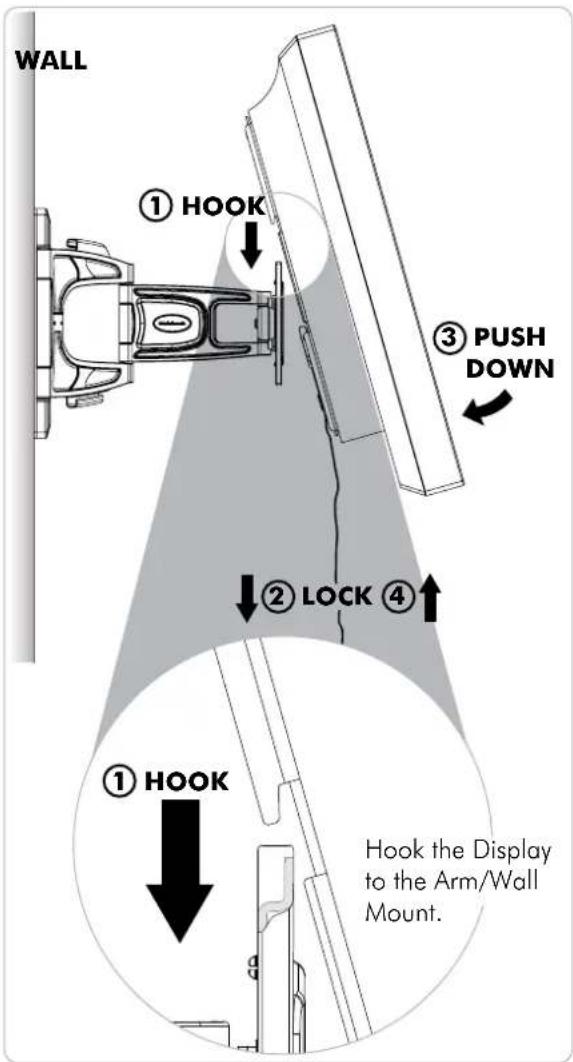

Step 6. Attach Locking Blocks to fully secure the Display

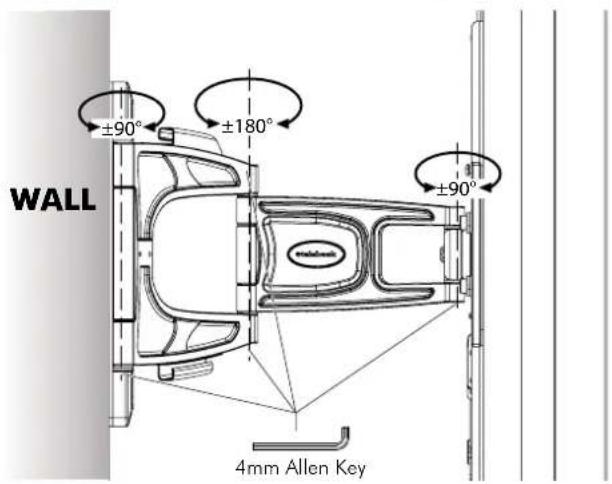
Step 7. Adjust Arm movement if necessary
Step 8. Adjust tilt and roll if necessary

Position your display to the desired viewing angle, using the angular movement allowed by the double ball mount.
Depending on the weight of the Display, it may be necessary to make adjustments to the double ball mount. If the display does not hold its position, or is too resistant, adjust the tension plate located at the rear of the double ball mount.
To adjust the tension plate, apply half a turn at a time to each nut. ENSURE NUTS ARE ADJUSTED EVENLY.
CHECK THE DISPLAY, and then adjust again if necessary.
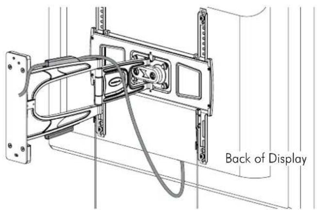
Step 9. Cable Management
Installation Complete


Brand : Atdec
Model : TH-2050-UFL
Category : Mount