TH-3060-UFH - Support Atdec - Free user manual and instructions
Find the device manual for free TH-3060-UFH Atdec in PDF.

User questions about TH-3060-UFH Atdec
0 question about this device. Answer the ones you know or ask your own.
Ask a new question about this device
Download the instructions for your Support in PDF format for free! Find your manual TH-3060-UFH - Atdec and take your electronic device back in hand. On this page are published all the documents necessary for the use of your device. TH-3060-UFH by Atdec.
USER MANUAL TH-3060-UFH Atdec
Display Mounting Screws Bag
M8 x 16mm (x4)
M8 x 25mm (x4)


M6 x 16mm (x4)
M6 x 25mm (x4)
Mount cap (x2)

Tools required:
- Philips head screwdriver
- 5mm (0.2") drill bit
- Power drill
- 10mm (0.39") masonary drill bit
IMPORTANT INFORMATION
! IMPORTANT - Install Telehook Flatscreen wall mount as per Installation Instructions
! This product supports a minimum load of 5kg (11lbs) and a maximum load of 25kg (55lbs)
! This product supports VESA mounting hole configurations from 200mm x 200mm to 400mm x 400mm
! The Manufacturer accepts no responsibility for incorrect installation.
Step 1. Check Components
Check you have received all parts against the Component Checklist and Hardware.
Step 2. Mounting Location
This product has a feature where the arm will automatically lock in position when pushed up against the wall to the left. If this feature is to be used allow clearance to the left when deciding the mounting location.

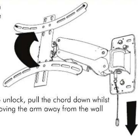
text_image
unlock, pull the chord down whilst moving the arm away from the wallStep 3. Install Arm to the wall
Masonry Wall Timber Stud wall
text_image
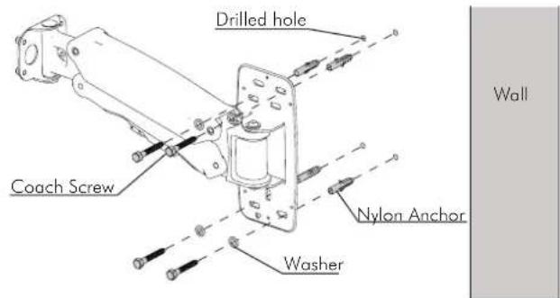
Drilled hole Coach Screw Nylon Anchor Washer Wall- Using a 10mm (0.39") masonary drill bit, Drill four holes, 60mm (2.4") deep.
- Secure the mounting plate to the wall using the Coach Screws and Nylon Anchors supplied.

text_image
Coach Screw Washer Drilled hole- Using a 5mm (0.2") drill bit, Drill three holes, 60mm (2.4") deep.
- Secure the mounting plate to the wall using the Coach Screws supplied.
NOTE: Use a stud finder to accurately locate the centre of the stud. Ensure that all screws fix securely into stud.
Step 4. Attach Wall Plate Covers
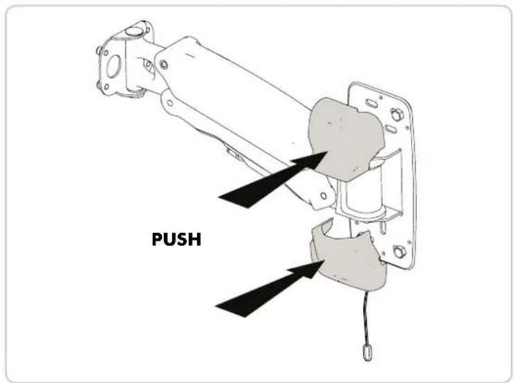
text_image
PUSHStep 5. Attach Display Mount to Arm
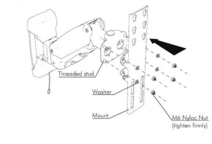
text_image
Threaded stud Washer Mount M6 Nyloc Nut (tighten firmly)Step 6. Horizontal Rotation Adjustment
text_image
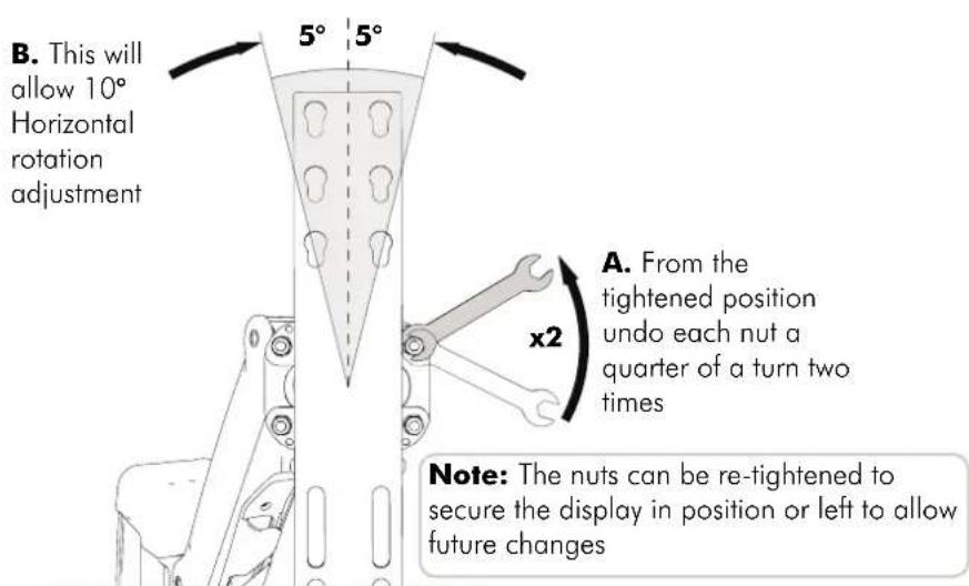
B. This will allow 10° Horizontal rotation adjustment 5° 5° A. From the tightened position undo each nut a quarter of a turn two times x2 Note: The nuts can be re-tightened to secure the display in position or left to allow future changesStep 7. Attach Screw Covers
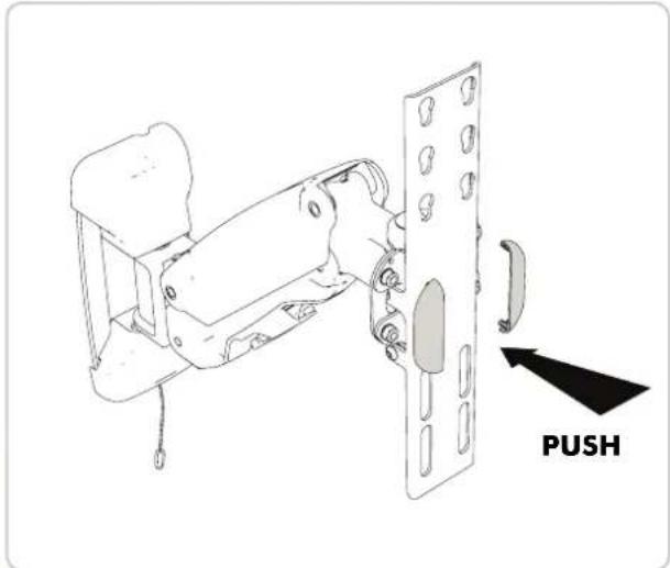
text_image
PUSHStep 8. Attach Mounting Rails To Display
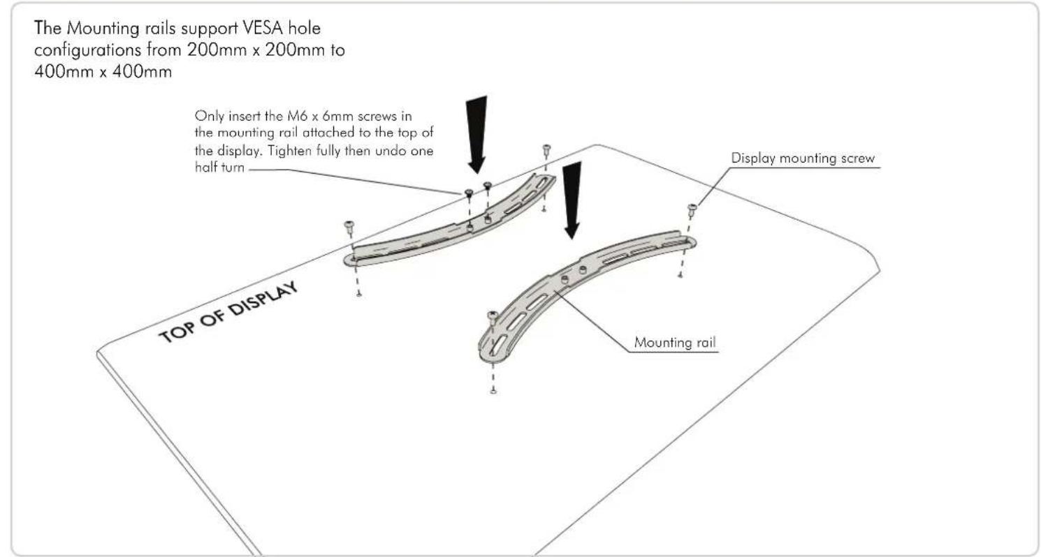
text_image
The Mounting rails support VESA hole configurations from 200mm x 200mm to 400mm x 400mm Only insert the M6 x 6mm screws in the mounting rail attached to the top of the display. Tighten fully then undo one half turn Display mounting screw TOP OF DISPLAY Mounting railStep 9. Attach Display to Display Mount
A. Prior to attaching your Display check which of the three pairs of keyhole mounting positions on the Display Mount to use that will also allow access to the lower mounting slots.
B. Hook the screws in the top mounting
bracket into your chosen
pair of keyhole mounting positions on the display mount
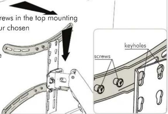
text_image
screws in the top mounting ur chosen screws keyholesC. Attach M6 x 6mm screws to the lower mounting rail, to secure the display
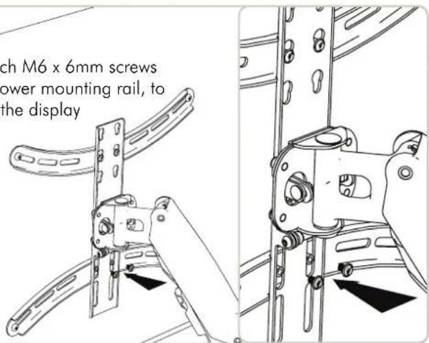
text_image
ch M6 x 6mm screws power mounting rail, to the displayStep 10. Display Height Adjustment
A. The Arm may need to be adjusted to suit the weight of the display

text_image
light of the display If the Display drops down the spring tension will need to be increased Wall If the Display rises the spring tension will need to be decreased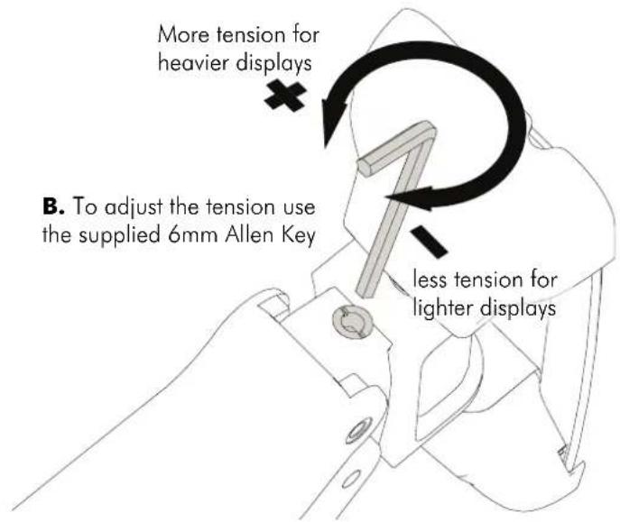
text_image
More tension for heavier displays B. To adjust the tension use the supplied 6mm Allen Key less tension for lighter displaysStep 11. Tilt Adjustment
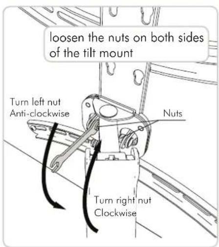
text_image
loosen the nuts on both sides of the tilt mount Turn left nut Anti-clockwise Nuts Turn right nut Clockwise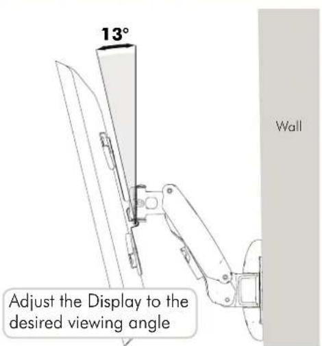
text_image
13° Adjust the Display to the desired viewing angle Wall
text_image
Tighten nuts to secure position Turn left nut Clockwise Nuts Turn right nut Anti-clockwiseInstallation complete
