
AF-AT - Mount Atdec - Free user manual and instructions
Find the device manual for free AF-AT Atdec in PDF.

| Product Type | Desktop Monitor Mount |
| Brand | Atdec |
| Model | AF-AT |
| Weight Capacity | 0 - 8 kg (0 - 17.6 lbs) |
| Mounting Options | Desk clamp (default or inverted), bolt-through |
| Clamp Thickness (Default) | 0 - 39 mm (0 - 1.5 in) |
| Clamp Thickness (Inverted) | 35 - 76 mm (1.4 - 3 in) |
| VESA Compatibility | Yes (VESA mount head included) |
| Pole Compatibility | Compatible with AF Poles and arms |
| Height Adjustment | Yes (manual via arm assembly) |
| Tilt Adjustment | Yes (support screen when adjusting) |
| Cable Management | Yes (cable stops included) |
| Tools Required | Power drill, drill bit, Phillips head screwdriver |
| Components Included | Clamp bracket, clamp plate, post, VESA head, arm assembly, cable stops |
| Material | Metal (steel/aluminum alloy) |
| Installation Type | Desk clamp or bolt-through |
| Maintenance | Periodically check tightness of screws and bolts |
| Safety | Ensure proper installation and weight limit not exceeded |
| Repairability | Modular design; individual components replaceable |
| Warranty | Refer to manufacturer |
Frequently Asked Questions - AF-AT Atdec
User questions about AF-AT Atdec
0 question about this device. Answer the ones you know or ask your own.
Ask a new question about this device
Download the instructions for your Mount in PDF format for free! Find your manual AF-AT - Atdec and take your electronic device back in hand. On this page are published all the documents necessary for the use of your device. AF-AT by Atdec.
USER MANUAL AF-AT Atdec
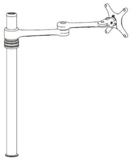
Desktop Monitor Mount
natural_image
Technical line drawing of a mechanical lever assembly (no text or symbols)COMPONENT CHECKLIST


REQUIRED TOOLS
- Power Drill
- Drill Bit
• Phillips Head Screwdriver
WEIGHT RANGE
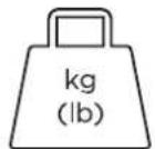
0 - 8kg (0 - 17.6lbs)
IMPORTANT INFORMATION
! Please ensure this product is installed as per these installation instructions.
! This product is compatible with the range of AF Poles and arms.
! The manufacturer accepts no responsibility for incorrect installation.
1. Desk overview
| The desk clamp bracket can be repositioned to suit different mounting surface thicknesses. | 1.1 Default 1.2 Inverted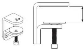 MIN THICKNESS - 0mm (0")MAX THICKNESS - 39mm (1.5") MIN THICKNESS - 0mm (0")MAX THICKNESS - 39mm (1.5") | 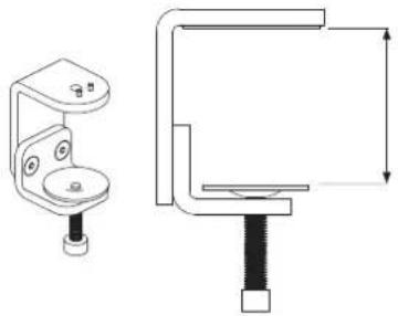 MIN THICKNESS - 35mm (1.4")MAX THICKNESS - 76mm (3") MIN THICKNESS - 35mm (1.4")MAX THICKNESS - 76mm (3") |
2. How to reconfigure desk clamp
2.1 Remove screws(M8 x 16mm Countersunk screw)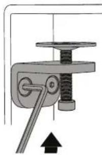 | 2.2 Remove clamp plate | 2.3 Invert bracket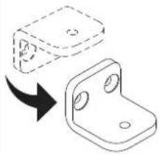 | 2.4 Replace clamp plate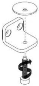 | 2.5 Reattach bracket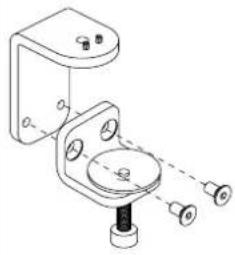 |
3. Post mount configuration
3.1 Attach clamp to post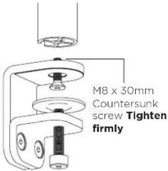 | 3.2 Place in desired location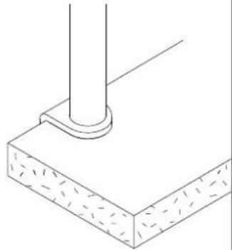 | 3.3 Screw pressure plates in andtighten firmly.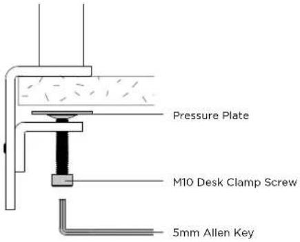 |
4. Bolt through
Dride:on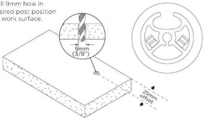 | 5.1 Attach plate to postAlign rear hole withhole on desk | 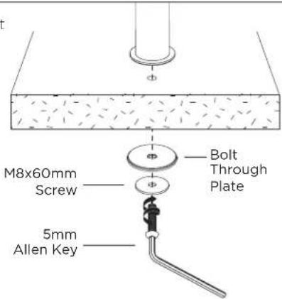 |
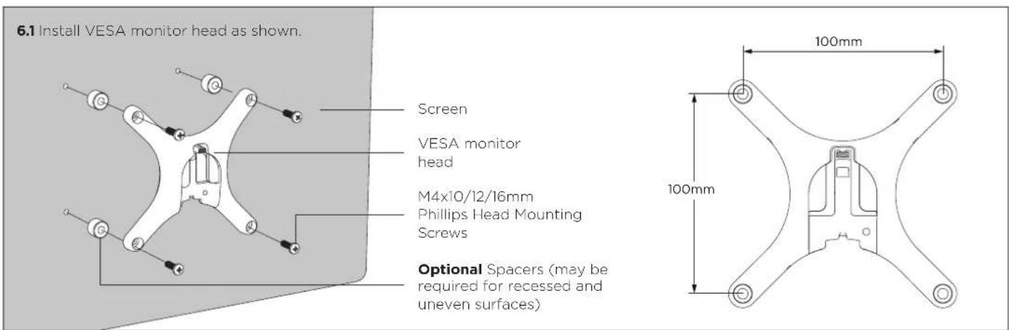
6. Install VESA monitor head
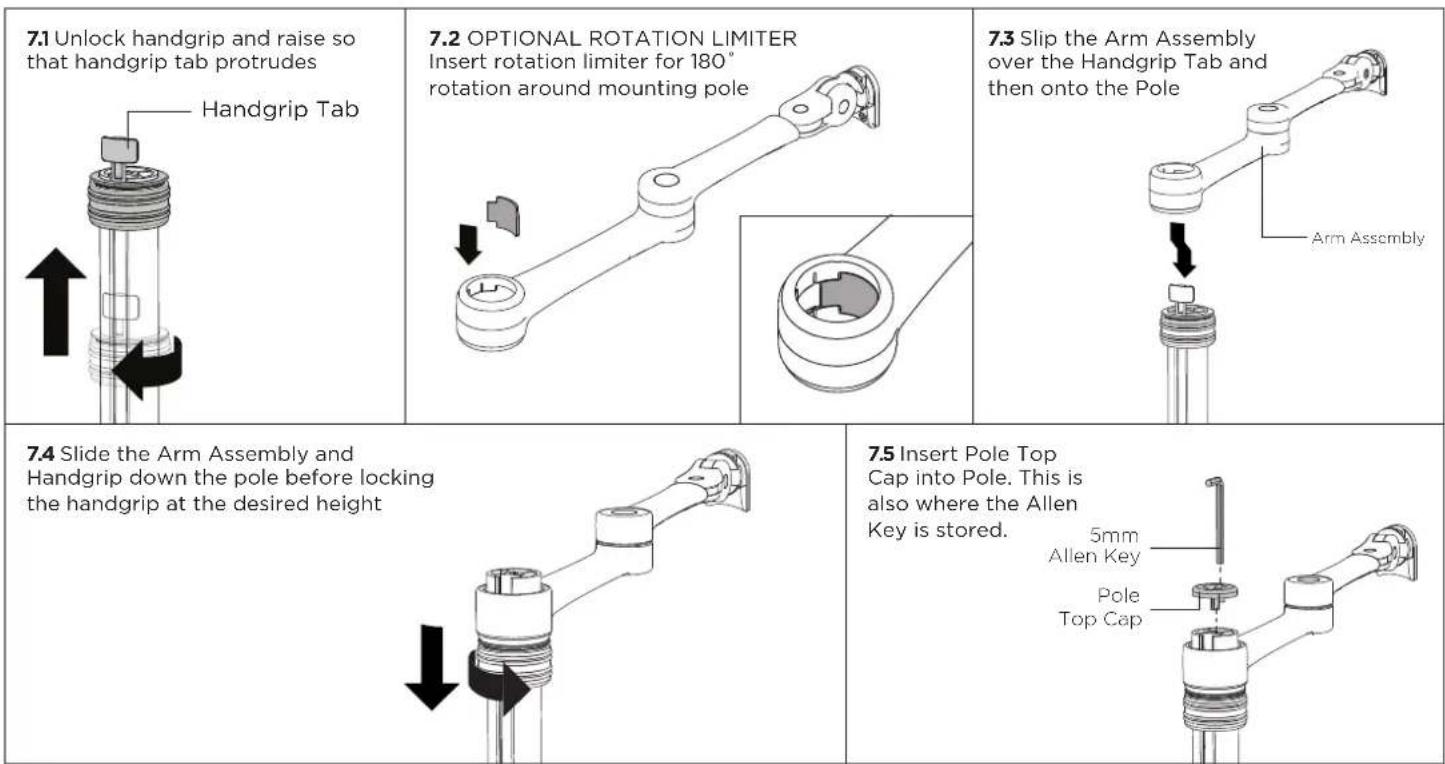
7. Install arm assembly
8. Mounting Monitor

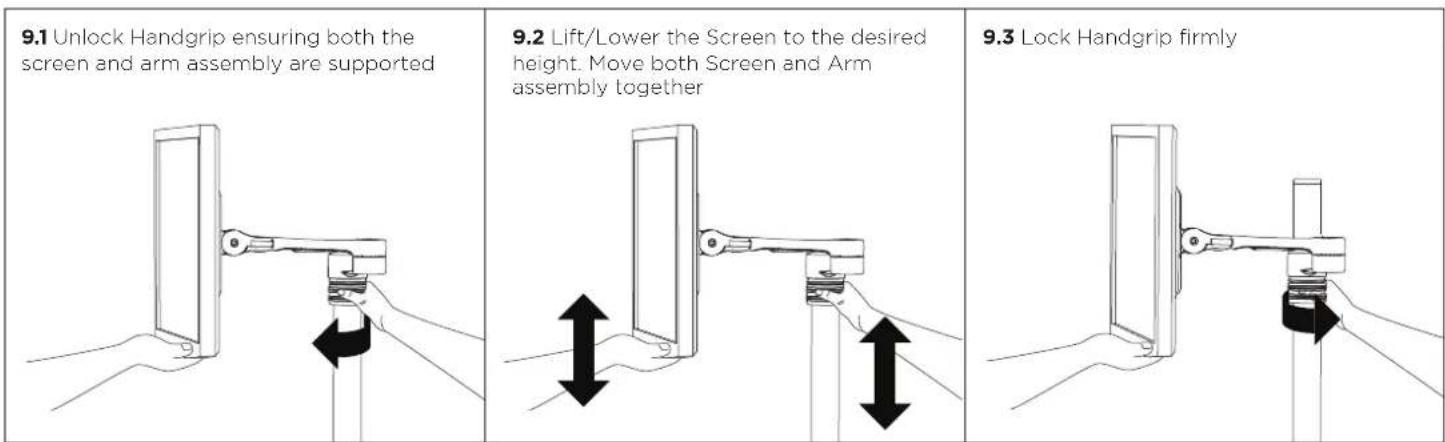
9. Adjusting Height
10. Cable Management
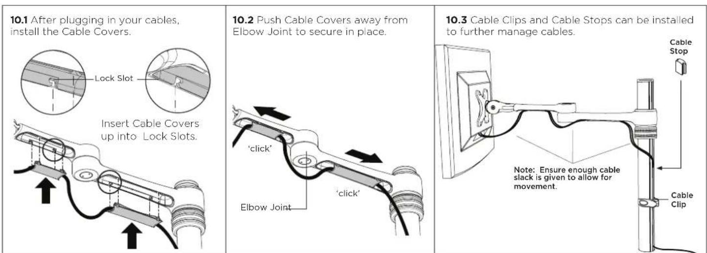
11. Insert Cable Stops

12. Adjusting the Display Bracket
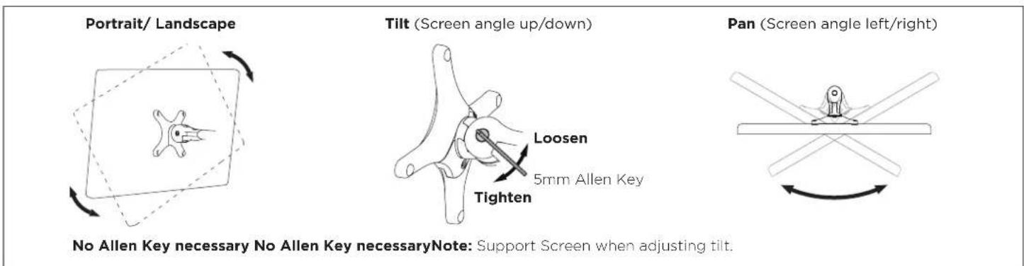
No Allen Key necessary No Allen Key necessaryNote: Support Screen when adjusting tilt.


- Desktop Monitor Mount
- REQUIRED TOOLS
- WEIGHT RANGE
- IMPORTANT INFORMATION
- Desk overview
- How to reconfigure desk clamp
- Post mount configuration
- Bolt through
- Install VESA monitor head
- Install arm assembly
- Mounting Monitor
- Adjusting Height
- Cable Management
- Insert Cable Stops
- Adjusting the Display Bracket
Brand : Atdec
Model : AF-AT
Category : Mount