SD-SA-DK-DB-BK - Accessory Atdec - Free user manual and instructions
Find the device manual for free SD-SA-DK-DB-BK Atdec in PDF.

User questions about SD-SA-DK-DB-BK Atdec
0 question about this device. Answer the ones you know or ask your own.
Ask a new question about this device
Download the instructions for your Accessory in PDF format for free! Find your manual SD-SA-DK-DB-BK - Atdec and take your electronic device back in hand. On this page are published all the documents necessary for the use of your device. SD-SA-DK-DB-BK by Atdec.
USER MANUAL SD-SA-DK-DB-BK Atdec
text_image
Swing Arm Assembly (x2) 16mm Cable Wrap (x2) Spacer Tube Assembly (x2) Threaded Rod and Top Cap (x1) Inner Tube PostDesk Clamp Box

natural_image
Simple line drawing of a box with a lid and internal components, no text or symbols present.
text_image
5mm Allen Key (x1) Pressure Plate (x1) M8 Desk Clamp Screw (x1) Desk Clamp Bracket (x1)Bits Box

Cable Wrap Applicator (x1)

Cable Manager Tube Clip (x1)
M8 Interscrew (x1)

Cable Clip (x4)

Washer (x1)
Base Casting (x1)

M8 Nyloc Nut (x1)

M4x16mm Countersunk Screw (x3)

2.5mm Allen Key (x1)

Extension Clip (x8)
Top Cap Tool (x1)
Mounting Fasteners

M4x10mm Screw (x8)

M4x12mm Screw (x8)

M4x16mm Screw (x8)
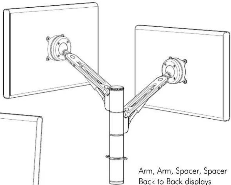
Possible Configurations
Spacedec Acrobat Swing Arm Double can be assembled in a number of different configurations depending on the users requirements.
Two such examples are shown below and right.
text_image
Arm, Arm, Spacer, Spacer Back to Back displays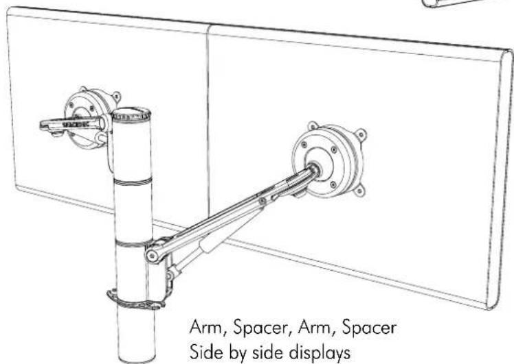
text_image
Arm, Spacer, Arm, Spacer Side by side displaysArm, Arm, Spacer, Spacer Back to Back displays

Component Checklist
Check you have received all parts against the Component Checklist on the previous page.

Assemble the Arm
B.1. Disassemble the Tube Assembly
You will need to disassemble the Tube Assembly before assembling the Swing Arm

text_image
before assembling the Swing Arm Top Cap and Threaded Rod Internal Tube Post Spacer Tube (x2)B.2. Assemble the Swing Arm
Assemble the Swing Arm in the desired configuration ensuring all components are used as shown.
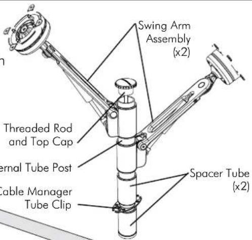
text_image
Swing Arm Assembly (x2) Threaded Rod and Top Cap Internal Tube Post Cable Manager Tube Clip Spacer Tube (x2)Mounting Options
C.1. Desk Clamp
C.1.1. Assemble the Desk Clamp
To assemble the Desk Clamp Assembly, first place the M8 Nyloc Nut inside the Base Casting with the Plastic Ring facing down, then screw the Base Casting on to the Desk Clamp Bracket using the M4x16mm Countersunk screws.
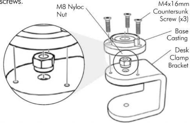
text_image
M8 Nyloc Nut M4x16mm Countersunk Screw (x3) Base Casting Desk Clamp BracketDESK CLAMP ADJUSTMENT RANGE

natural_image
Technical line drawing of a mechanical assembly with no visible text or symbolsSuits 12mm (1/2") to 38mm (11/2") thick work surfaces
-Pressure Plate
M8 Desk Clamp Screw
NOTE: It is recommended that the Desk Clamp be attached to the rear or side edge of the work surface
Adjust the Desk Clamp to suit your desk thickness by turning the M8 Desk Clamp. Screw with the supplied 5mm Allen Key
C.1.2. Attaching the Desk Clamp
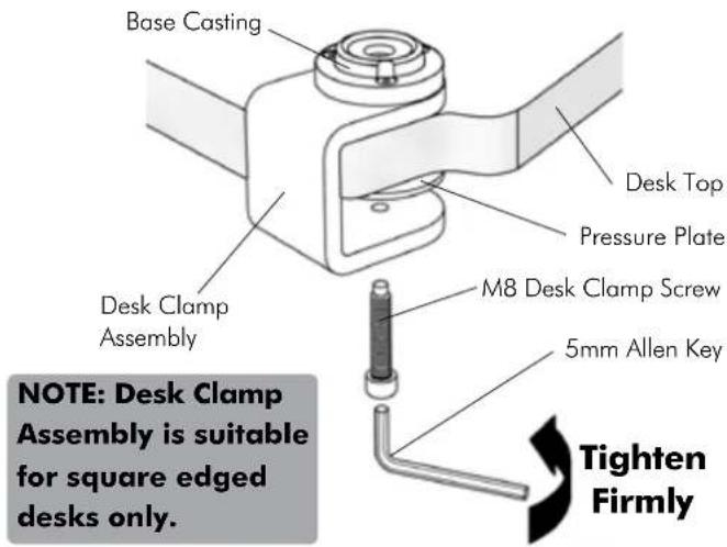
text_image
Base Casting Desk Top Pressure Plate M8 Desk Clamp Screw 5mm Allen Key Desk Clamp Assembly NOTE: Desk Clamp Assembly is suitable for square edged desks only. Tighten FirmlyC.1.3. Attaching the Swing Arm Post
Use the Top Cap Tool to tighten the Threaded Rod into the Base Casting as shown below.
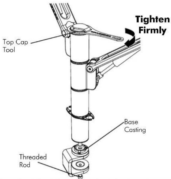
text_image
Tighten Firmly Top Cap Tool Base Casting Threaded RodC.2. Bolt Through
C.2.1. Drill Mounting Hole
Drill a 13mm ( 12 ) hole in your work surface at the desired location for your arm.
C.2.2. Install as shown
Insert the M8 Interscrew up through the hole in the work surface.
Using both hands, secure the M8 Interscrew with the 5mm Allen Key supplied in the Desk Clamp Box and use the other hand to tighten the Threaded Rod into the Interscrew with the supplied Top Cap Tool. (see diagram C.2.3.)

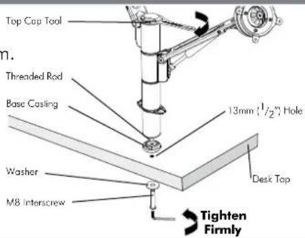
text_image
Top Cap Tool Threaded Rod Base Casting 13mm (1/2"), Hole Washer M8 Interscrew Desk Top Tighten Firmly
Attaching the Displays
100mm x 100mm (4" x 4") mounting hole pattern
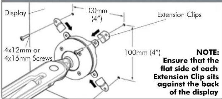
text_image
Display 4x12mm or 4x16mm Screws 100mm (4") Extension Clips 100mm (4") NOTE: Ensure that the flat side of each Extension Clip sits against the back of the display75mm x 75mm (3" x 3") mounting hole pattern
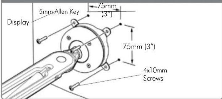
text_image
Display 5mm-Allen Key 75mm (3") 75mm (3") 4x10mm Screws
Installing Cable Management
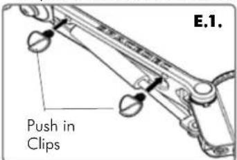
E.1. Push the four supplied Cable Clips into the holes on the underside of the Swing Arm Double as shown.
E.2. Feed the cables into the Cable Wrap Applicator.
E.3. Insert the Cable Wrap Applicator into the Cable Wrap as shown.
E.4. Squeeze the nose of the Applicator and place inside the Cable Wrap ensuring that the opening edges of the Cable Wrap face towards the nose of the applicator as shown in diagram.
text_image
E.1. Push in Clips
text_image
E.2. E. Nose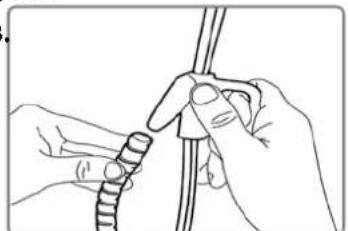
natural_image
Line drawing of hands tying a knot using a rope (no text or symbols)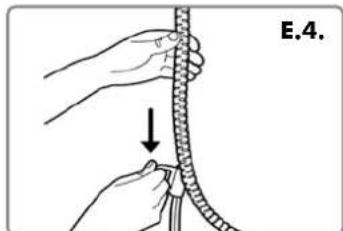
natural_image
Illustration of hands tying a rope knot with a pull (no text or symbols)
Attaching the Cable Wrap to the Arm
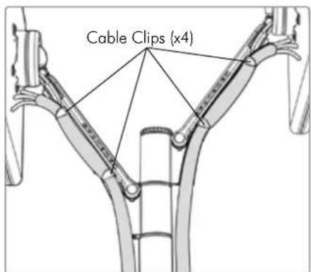
F.1. Position the displays at their highest possible position to ensure that there is sufficient cabling at the end of the arm so the cables are not stretched or pulled out when the displays are moved.
text_image
Cable Clips (x4)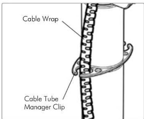
text_image
Cable Wrap Cable Tube Manager ClipRecommended Mounting Position
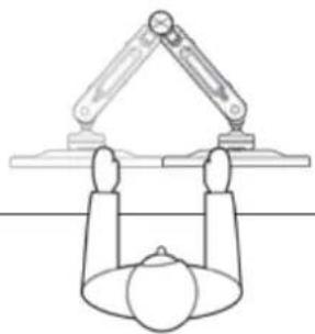
When mounting the Spacedec Acrobat Swing Arm Double, ensure the correct focal distance can be achieved for ultimate visual comfort.
natural_image
Simple line drawing of a robotic arm above a spherical object, with no text or symbols present.
Adjusting the Display
The Spacedec Acrobat Swing Arm Double comes factory set to support 6kg displays. Adjust the arm to suit the weight of your display as shown in the following steps:
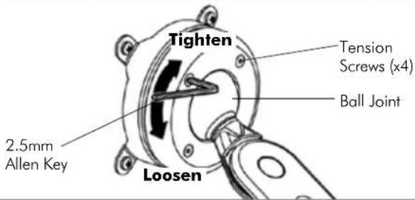
G.1. Adjusting the Ball Joint Resistance
Depending on the weight of the display, it may be necessary to make adjustments to the Ball Joint Mechanism. If the display doesn't hold its position or is too resistant, adjust the four tension screws located around the Ball Joint (see diagram on the right) using the supplied 2.5mm Allen Key. Check the display, and then adjust again if necessary.
NOTE: Be sure to adjust screws evenly.
text_image
Tighten Tension Screws (x4) Ball Joint 2.5mm Allen Key LoosenG.2. Adjusting the Pivot Head Resistance
It is possible to control the amount of resistance in the Pivot Head to suit your display.
To increase the resistance of the Pivot Head to suit heavier displays, use the 5mm Allen Key supplied in the Desk Clamp Box to tighten the interscrew in a clockwise direction.
To decrease the resistance of the Pivot Head to suit lighter displays, loosen the interscrew in an anti-clockwise direction.
NOTE: It is recommended the Pivot Head be left at the factory setting for best performance.

text_image
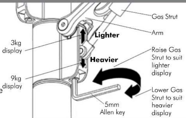
it e the w in Pivot Head Interscrew 5mm Allen Key Loosen TightenG.3. Adjusting the Swing Arm/Gas Strut Resistance
G.3.1. Depending on the weight of the display, it may be necessary to adjust the arm. This can be done by using the 5mm Allen Key supplied in the Desk Clamp Box.
G.3.2. If the arm tends to automatically rise or fall when the display is attached, it will be necessary to make small adjustments to the gas strut. (see diagram on the right)
G.3.3. If the arm tends to rise, the gas strut position should be raised. If the arm tends to fall, the gas strut position should be lowered.