
AWMS-46W35-S - Monitor Stand Atdec - Free user manual and instructions
Find the device manual for free AWMS-46W35-S Atdec in PDF.


| Product Type | Monitor Stand |
| Brand | Atdec |
| Model | AWMS-46W35-S |
| Dimensions (W x D x H) | 23.6 x 15.7 x 7.9 inches (600 x 400 x 200 mm) |
| Weight | 4.4 lbs (2 kg) |
| Weight Capacity | 22 lbs (10 kg) |
| VESA Compatibility | 75x75 mm, 100x100 mm |
| Material | Steel frame, plastic base |
| Height Adjustment | Yes, gas spring (range: 4.7 inches) |
| Tilt Adjustment | Yes, -5° to +15° |
| Swivel Adjustment | Yes, ±90° |
| Rotation (Landscape/Portrait) | No |
| Cable Management | Yes, integrated clips |
| Mounting Type | Clamp or grommet (not included) |
| Power Supply | None (passive stand) |
| Cleaning Instructions | Wipe with soft, damp cloth; do not use solvents |
| Safety Features | Anti-slip base, gas spring locking mechanism |
| Spare Parts Availability | Contact Atdec support for replacement parts |
| Warranty | 2 years |
Frequently Asked Questions - AWMS-46W35-S Atdec
User questions about AWMS-46W35-S Atdec
0 question about this device. Answer the ones you know or ask your own.
Ask a new question about this device
Download the instructions for your Monitor Stand in PDF format for free! Find your manual AWMS-46W35-S - Atdec and take your electronic device back in hand. On this page are published all the documents necessary for the use of your device. AWMS-46W35-S by Atdec.
USER MANUAL AWMS-46W35-S Atdec
Single Monitor Arm on Wall Mount

natural_image
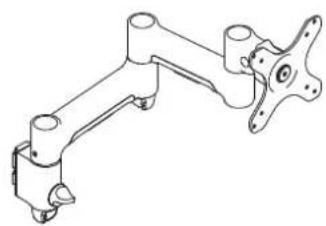
Technical line drawing of a mechanical arm assembly (no text or symbols)COMPONENT CHECKLIST RANGE
natural_image
Technical line drawing of a mechanical linkage component (no text or symbols)A
AWM-A46
460 Arm
(x1)

B
AWM-W35
350 Wall Channel
(x1)
Walk
CONTENTS
| 350 Wall Channel | AWM-W35 |
| Page 2 | Component Checklist |
| Page 3 | Channel Installation |
| 460 Arm | AWM-A46 |
| Page 4 | Component Checklist |
| Page 5 | Arm Installation |

natural_image
Technical line drawing of a vertical cylindrical component with mounting holes and three circular features on both sides (no text or symbols)COMPONENT CHECKLIST

A
Wall channel
(x1)

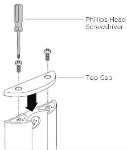
B Top Cap (x1)

C
Top Cap
Screws
(x2)

D
M6 x 50mm
Countersunk
Screw (x3)

E
Nylon
Anchor (x3)

REQUIRED TOOLS
- Power Drill
- 4mm ( ^5/_32 ) Drill Bit
- 8mm ( ^5/_16 ) Drill Bit
• Phillips Head Screwdriver
IMPORTANT INFORMATION
! Please ensure this product is installed as per these installation instructions.
! This product is compatible with Atdec modular (AWM) products.
! The manufacturer accepts no responsibility for incorrect installation.
1. Install Wall Channel - Ensure all fasteners are installed
1.1 Masonry 1.2 Timber stud


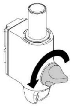
2. Fit channel clamp to wall channel
2.1 Ensure knob is undone. 2.2 Slide clamp into channel.
natural_image
Mechanical component diagram showing a rotating shaft and housing with a curved arrow indicating rotation (no text or symbols)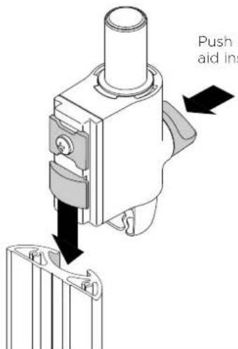
2.3 Hold clamp in desired position on post and turn knob to lock in place.

natural_image
Mechanical component diagram showing a rotating shaft and housing with a curved arrow indicating rotation (no text or symbols)3. Install top cap 4. Cable clips
3.1 Attach Top Cap
4.1 Push the cable down into the Cable Clip.
Note: Cable clips sold separately in packs of four.
4.2 Insert one side of the Cable Clip into the Channel on the Post assembly or Wall Channel, before pushing the other side in.

natural_image
Close-up of hands holding a cable with a black arrow indicating cable direction (no text or symbols)

natural_image
Technical line drawing of a mechanical linkage assembly (no text or symbols)COMPONENT CHECKLIST

natural_image
Technical line drawing of a mechanical linkage component (no text or symbols)A
Monitor Arm (x1)

B
VESA Head (x1)

C
Post Clamp (x1)

D
Screw
M4x25mm
(x4)

E
Screw M4x16mm (x4)

F
Screw
M4x12mm
(x4)

G
Spacer (x4)

H
Security screw (x1)

|
4mm
allen key
(x1)

REQUIRED TOOLS
• Phillips Head Screwdriver
WEIGHT RANGE
Flat Monitors
0 - 12kg
(0 - 26.5lbs)
Curved Monitors
0 - 8kg
(0 - 17.6lbs)
Monitor weight should be within the weight range of all modular elements that make up the complete monitor mounting solution.
IMPORTANT INFORMATION
! Please ensure this product is installed as per these installation instructions.
! The manufacturer accepts no responsibility for incorrect installation.
! This product is compatible with Atdec AWM Series products.
! Curved monitors, deep devices (such as all-in-one PCs) and offset VESA locations exert additional leverage that can exceed the capacity of the mount even though the monitor weight may be within the stated range. Please contact Atdec if you would like further information.
1. Fix clamp to Post or Wall Channel

2. Set arm rotation to 180° (optional)
Note rotation is set to 360^ by default.

3. Fit arm onto post clamp

4. Attach VESA head to monitor
4.1 VESA mounting compatibility

Note: For other sizes, use a suitable adaptor plate (sold separately).
4.2 Screw the VESA head onto monitor

natural_image
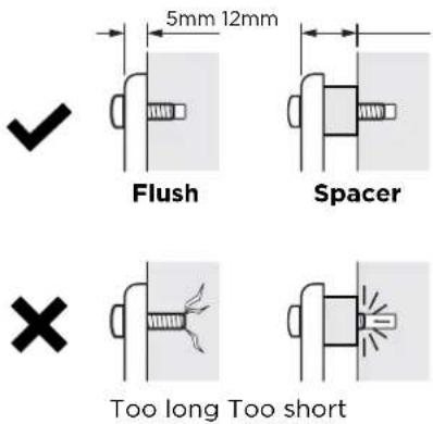
Pure mechanical diagram of a four-pronged valve or pump assembly without any text, labels, or symbolsNote spacers may be required for curved, recessed or uneven monitor surfaces.
4.3 Ensure the correct screw length is used to attach the monitor.
5. Mount monitor
5.1 Insert VESA head into the monitor arm

5.2 Ensure that the VESA head sits flush within the monitor arm. There should be no gap

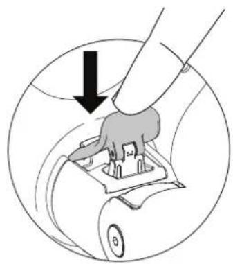
5.3 Push the lever down to secure it to the arm assembly
natural_image
Diagram showing a hand pressing down on a mechanical component with a black arrow indicating downward motion (no text or symbols present)6. Adjust tilt tension & Install security screw
6.1 Use the allen key to adjust the tilt tension until the monitor holds in a vertical position at the end of the arm.
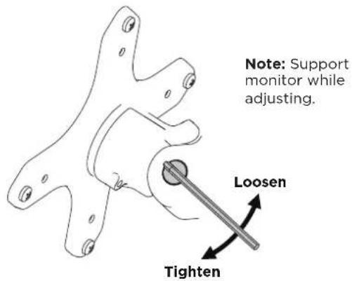
6.2 OPTIONAL security screw
To install the optional security screw tilt the head upwards

natural_image
Mechanical assembly diagram showing a turning tool interacting with a bracket (no text or symbols present)6. Monitor arm cable management
6.1 Plug cables into the monitor and route the cables down the arm using the cable hooks and clips

7. Post cable management
7.1 Push the cable down into the cable clip
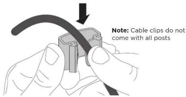
7.2 Push cable clip into post channel

natural_image
Illustration of a hand inserting a cable into a mechanical component (no text or symbols)7.3 Recommended post cable cover position for double or triple arm set-ups
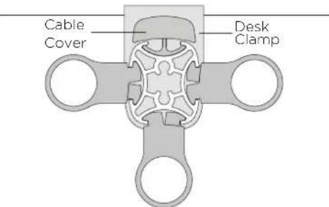
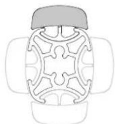
7.4 To reposition the cable cover, pull it straight up and out of the post and insert it into any of the available channels

Note: The cable cover shown does not come with all posts
natural_image
Top-down line drawing of a mechanical component with symmetrical cutouts and a flat top (no text or symbols)Alternative cable cover positions
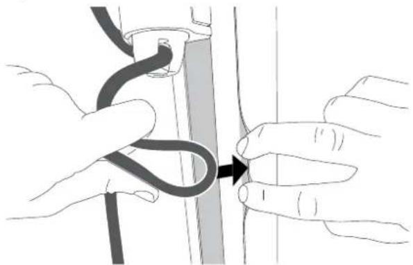
7.5 Loop cable and insert into cable cover
natural_image
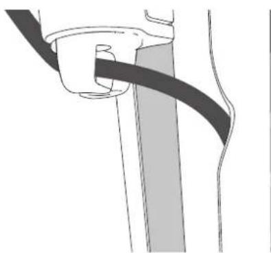
Illustration of hands performing a medical procedure on a vertical tube, with no visible text or symbols7.6 Feed remaining cable into cover
natural_image
Diagram of a cable being inserted into a cylindrical component (no text or symbols)
- Single Monitor Arm on Wall Mount
- COMPONENT CHECKLIST
- REQUIRED TOOLS
- IMPORTANT INFORMATION
- Install Wall Channel - Ensure all fasteners are installed
- Fit channel clamp to wall channel
- Install top cap 4. Cable clips
- WEIGHT RANGE
- Flat Monitors
- Curved Monitors
- Fix clamp to Post or Wall Channel
- Set arm rotation to 180° (optional)
- Fit arm onto post clamp
- Attach VESA head to monitor
- Mount monitor
- Adjust tilt tension & Install security screw
- Monitor arm cable management
- Post cable management
Brand : Atdec
Model : AWMS-46W35-S
Category : Monitor Stand