PSTND13 - Pregnant Pyle - Free user manual and instructions
Find the device manual for free PSTND13 Pyle in PDF.

User questions about PSTND13 Pyle
0 question about this device. Answer the ones you know or ask your own.
Ask a new question about this device
Download the instructions for your Pregnant in PDF format for free! Find your manual PSTND13 - Pyle and take your electronic device back in hand. On this page are published all the documents necessary for the use of your device. PSTND13 by Pyle.
USER MANUAL PSTND13 Pyle
text_image
P PYLE® HomePSTND13
Heavy Duty Steel Double Support Bookshelf Speaker Stands
http://www.pyleaudio.com
Thank you for purchasing the PSTND13. Use this pair of bookshelf speaker stands to keep your speakers stable and secure. Heavy-duty steel construction looks great, conceals cables, and optimizes the performance of your speaker by minimizing floor distortion. The columns can even be sand-loaded to deaden resonance and increase stability. Adjustable spikes on bottom of stand provide additional security. Maximum weight capacity: 35 lbs. Setup height: 13".
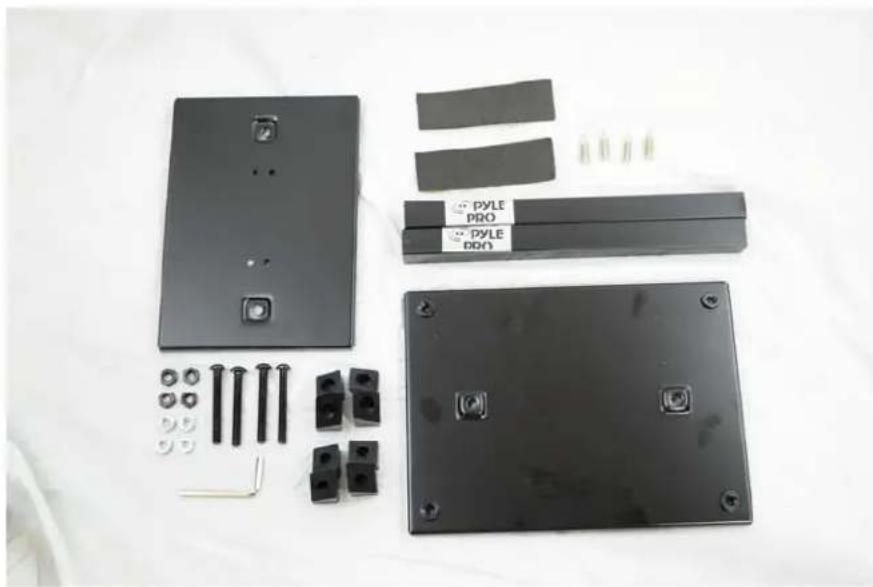
Your kit includes two (2) sets of the following items:
natural_image
Disassembled black electronic components including a panel, connectors, and battery pack (no text or symbols visible)1 x large base plate
1 x speaker plate
2 x steel columns
2 x sticky-backed pads
4 x long black screws
4 x silver spikes
4 x silver nuts
4 x black nuts
8 x plastic stoppers
1 x Allen wrench
Note: your package may include a different amount of black and silver nuts. They are the same size and interchangeable.
The following instructions are for the construction of one of your stands. To build the second stand, simply follow the directions from the beginning again.
- Begin with the larger base plate. Insert two (2) black screws through the underside of the plate.
natural_image
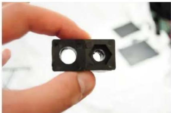
Black rectangular electronic component with two metal pins, placed on a white fabric background (no text or symbols visible)- Prepare the plastic stoppers. For each screw, you'll need one of each kind. They look like this:
natural_image
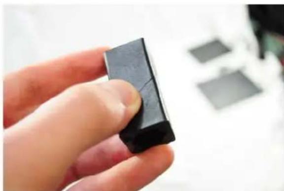
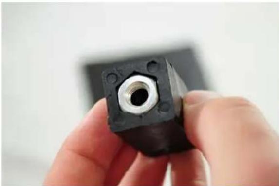
Hand holding a black mechanical component with two circular holes, no visible text or symbolsNotice one has a round hole and the other has a hex hole. You can put them together like this:
natural_image
Close-up of a hand holding a black rectangular object, possibly a small electronic component or tool, with blurred background items (no visible text or symbols)- Place a nut in the hex-holed plastic stopper and screw this whole structure each black screw with the nut facing up, or away from the plate. For now, keep the nuts loose -- the two plastic stoppers should not be tight yet. You should be able to line them up as in step 2.
natural_image
Close-up of a hand holding a black mechanical component with a central hole (no visible text or symbols)
natural_image
Black rectangular electronic component with mounting holes and a central screw, placed on a white surface (no text or symbols visible)
natural_image
Black rectangular electronic component with two small cylindrical pins, placed on a white fabric surface (no text or symbols visible)- Now, fit the two steel columns onto each pole. You may need pliers to adjust the fit.

natural_image
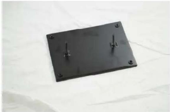
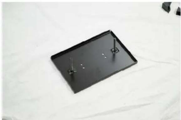
Black metal support base with two vertical pins labeled '700' and '500', placed on a white surface (no text or symbols on the base itself)- Set the bottom plate aside for now. Next, get the smaller top plate and insert the screws from the top. When upside-down, the plate should look like this:
natural_image
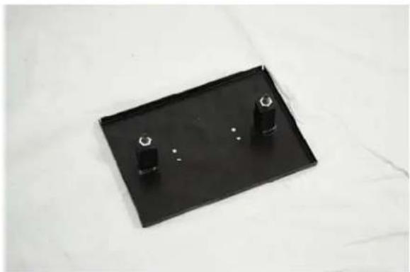
Black rectangular tray with two metal pins, placed on a white surface (no text or symbols visible)- Repeat the stopper procedure for this plate; line up two rubber stoppers with the hex side up, slide on the plastic stopper combo, and then loosely screw on a nut to hold into place.
natural_image
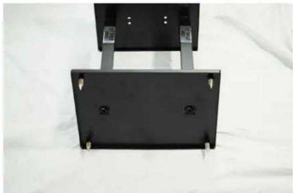
Black rectangular tray with two small black cylindrical objects on top, placed on a white surface (no text or symbols visible)- Take the complete top plate and fit it onto the bottom plate. Again, you may need to adjust the fit with pliers.

natural_image
Metal mechanical support base with two mounting holes, displayed on a white fabric background (no text or symbols visible)- Now, tighten all the screws to secure the stand. Tightening the screws causes the stoppers to expand, holding the steel poles in place.

natural_image
Close-up of a hand holding a metal tool inserted into a black plastic sheet with a small hole (no text or symbols visible)Note: Steps 9 and 10 are optional. The pads will help prevent your stand from resonating, and the spikes will isolate your stand from the desk or carpet. They are not necessary, but may improve the sound of your speakers.
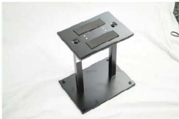
- Peel the protective paper off the back of the pads and stick them on the top of your stand. This will protect your speaker and help isolate sound from resonating in the stand.
natural_image
Metallic rectangular electronic device with two slots and mounting holes, placed on a white surface (no text or symbols visible)- From the bottom, screw each spike into the four remaining holes.
natural_image
Black rectangular electronic device with mounting brackets and mounting holes, placed on a white fabric background (no text or symbols visible)Congratulations! Your stand is complete. To build the other stand in your pair, simply repeat these instructions from step 1.
Be sure to fill out your warranty card or submit your product registration online at www.pyleaudio.com.
Product Specifications
• One Pair of Speaker Stand For A Bookshelf / Monitor / Speaker Stand
• Perfect For Home, Project Or Professional Recording Studios
- All-Steel, Attractive Design Incorporating Cable Management
• Vertical Columns May Be Sand Loaded To Deaden Sound And Increase Stability
- Heavy-Duty Steel Construction With Black Finish
- Conceals Cables For A Great Looking Setup
- Double-Support Provides Security And Strength With Style
- Adjustable Spikes On Bottom For Additional Stability
• Maximum Weight Capacity: 35.0Lbs.
- Setup Height: 13"
• Product Weight: 5.6Lbs
- Tube Diameter: 2 Pcs X 1.2" × 12.0"
- Base Plate Size: 8.30" × 11.30"