
Courier USR3500 - Router USRobotics - Free user manual and instructions
Find the device manual for free Courier USR3500 USRobotics in PDF.

| Brand | USRobotics |
| Model | Courier USR3500 |
| Product Type | Cellular Router (2G/3G) |
| Power Supply Voltage Range | 4.75V to 32V DC (nominal 13.2V) |
| Power Consumption (Connected Mode, GSM 850 PCL5) | 420mA average at 4.75V, 107mA at 13.2V; peak 3625mA at 4.75V |
| Interfaces | 10-pin Micro-Fit (GPIO, ON/OFF, power), 15-pin Sub-D serial (RS232), Mini-B USB, SIM socket, SMA main RF, MMCX secondary RF, MMCX GPS RF |
| GPS | Standalone and A-GPS, L1 frequency, NMEA sentences, active antenna bias (5V) |
| Cellular Bands | GSM850, E-GSM900, DCS1800, PCS1900; UMTS Bands I, II, V, VI, VIII |
| Operating Modes | Active, Sleep, Alarm (low power), Connected, Transfer |
| LED Indicator | Red LED for operational status (can be disabled in Sleep mode) |
| Real Time Clock | Internal RTC with backup capacitor, up to 30 hours retention when unpowered |
| Compliance | FCC Part 22/24, IC RSS-132/133, CE (EN 301 511, EN 301 908-2, EN 301 489 series), IEC 60950 safety |
| Environmental Protection | Designed for fixed/mobile installations; not for portable use (<20cm from body) |
| Reset | External reset pin (active low, min 200µs) |
| Care and Maintenance | Avoid extreme temperatures, dust, moisture; do not disassemble; use only USRobotics accessories |
Frequently Asked Questions - Courier USR3500 USRobotics
User questions about Courier USR3500 USRobotics
0 question about this device. Answer the ones you know or ask your own.
Ask a new question about this device
Download the instructions for your Router in PDF format for free! Find your manual Courier USR3500 - USRobotics and take your electronic device back in hand. On this page are published all the documents necessary for the use of your device. Courier USR3500 by USRobotics.
USER MANUAL Courier USR3500 USRobotics
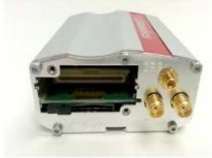
natural_image
Exterior view of a white electronic device with ports and a black antenna (no visible text or symbols)Important Notice
Due to the nature of wireless communications, transmission and reception of data can never be guaranteed. Data may be delayed, corrupted (i.e., have errors) or be totally lost. Although significant delays or losses of data are rare when wireless devices are used in a normal manner with a well-constructed network, the modem should not be used in situations where failure to transmit or receive data could result in damage of any kind to the user or any other party, including but not limited to personal injury, death, or loss of property. Neither Sierra Wireless nor USRobotics accepts any responsibility for damages of any kind resulting from delays or errors in data transmitted or received using the modem, or for failure of the modem to transmit or receive such data.
Safety and Hazards
Do not operate the modem in areas where cellular modems are not advised without proper device certifications. These areas include environments where cellular radio can interfere such as explosive atmospheres, medical equipment, or any other equipment which may be susceptible to any form of radio interference. The modem can transmit signals that could interfere with this equipment. Do not operate the modem in any aircraft, whether the aircraft is on the ground or in flight. In aircraft, the modem MUST BE POWERED OFF. When operating, the modem can transmit signals that could interfere with various onboard systems.
Note: Some airlines may permit the use of cellular phones while the aircraft is on the ground and the door is open. Modems may be used at this time.
The driver or operator of any vehicle should not operate the modem while in control of a vehicle. Doing so will detract from the driver or operator's control and operation
Notwithstanding the foregoing, in no event shall Sierra Wireless or USRobotics and/or their respective affiliates aggregate liability arising under or in connection with the Sierra Wireless/USRobotic product, regardless of the number of events, occurrences, or claims giving rise to liability, be in excess of the price paid by the purchaser for the Sierra Wireless /USRobotics product.
Customer understands that neither Sierra Wireless nor USRobotics is providing cellular or GPS (including A-GPS) services. These services are provided by a third party and should be purchased directly by the Customer.
Reference Guide
SPECIFIC DISCLAIMERS OF LIABILITY: CUSTOMER RECOGNIZES AND ACKNOWLEDGES SIERRA WIRELESS IS NOT RESPONSIBLE FOR AND SHALL NOT BE HELD LIABLE FOR ANY DEFECT OR DEFICIENCY OF ANY KIND OF CELLULAR OR GPS (INCLUDING A-GPS) SERVICES.
Patents
This product may contain technology developed by or for Sierra Wireless, Inc.
This product includes technology licensed from QUALCOMM ^® .
This product is manufactured or sold by Sierra Wireless, Inc. or its affiliates under one or more patents licensed from InterDigital Group and MMP Portfolio Licensing.
Copyright
© 2014 USRobotics. All rights reserved.
Trademarks
USRobotics ^® , Courier ^TM and the USRobotics logo are registered trademarks of USRobotics.
Sierra Wireless ^® , AirPrime ^® , AirLink ^® , AirVantage ^® and the Sierra Wireless logo are registered trademarks of Sierra Wireless.
Windows ^® is a registered trademark of Microsoft Corporation.
QUALCOMM ^® is a registered trademark of QUALCOMM Incorporated. Used under license.
Document History
| Version | Date | Updates |
| 1.0 | Initial release |
Contents
CONTENTS....6
LIST OF FIGURES 8
LIST OF TABLES....9
- FUNCTIONAL SPECIFICATIONS.... 11
1.1. Functional Architecture.... 11
1.2. RF Functionalities.... 12
1.3. Operating System.... 12
- TECHNICAL SPECIFICATIONS .... 13
2.1. Power Supply 13
2.2. Mechanical Specifications 14
- INTERFACES 15
3.1. Front Interface 15
3.1.1. Power Supply Connector 15
3.1.2. Serial Interface 21
3.1.3. USB Interface 29
3.2. Back Interface.... 30
3.2.1. SIM Interface 30
3.2.2. RF Interface.... 31
- SIGNALS AND INDICATORS 37
Reference Guide
7. RECOMMENDATIONS WHEN USING THE USR3500 ON TRUCKS 48
7.1. Recommended Power Supply Connection on Trucks 48
7.2. Technical Constraints on Trucks 49
8. RELIABILITY COMPLIANCE AND RECOMMENDED STANDARDS....50
8.1. Reliability Compliance 50
8.2. Applicable Standards Listing 50
8.3. Environmental Specifications 51
8.3.1. Function Status Classification 52
9. CERTIFICATION COMPLIANCE AND RECOMMENDED STANDARDS...... 53
9.1. Certification Compliance....53
9.2. Applicable Standards Listing 54
10. SAFETY RECOMMENDATIONS.... 55
10.1. General Safety....55
10.2. RF Safety 57
10.2.1. General 57
10.2.2. Exposure to RF Energy 57
10.2.3. Efficient Modem Operation....57
10.3. Vehicle Safety 57
10.4. Care and Maintenance 58
10.5. Your Responsibility....58
11.REFERENCE DOCUMENTS....59
11.1. Firmware Documentation 59
List of Figures
Figure 1. Functional Architecture....11
Figure 2. RF Architecture....12
Figure 3. USR3500 Mechanical Drawing....14
Figure 4. Front Interface ....15
Figure 5. Power Supply Connector....16
Figure 6. Equivalent Circuit of V _IL , Vref = 2.8V....17
Figure 7. Equivalent Circuit of V _IH , Vref = 2.8V....18
Figure 8. Equivalent Circuit of V _OL , Vref = 2.8V....18
Figure 9. Equivalent Circuit of V _OH , Vref = 2.8V .....18
Figure 10. Equivalent Circuit of V_IL , V_ref > 2.8V .....19
Figure 11. Equivalent circuit of V _IH , Vref > 2.8V ....19
Figure 12. Equivalent circuit of V_OL , V_ref > 2.8V .....19
Figure 13. Equivalent circuit of V_OH , V_ref > 2.8V ..... 19
Figure 14. 15-Pin Serial Connector ....21
Figure 15. RS232 Serial Link Signals ....23
Figure 16. V24 Serial Link Implementation for a 5-wire UART....24
Figure 17. V24 Serial Link Implementation for a 4-wire UART....24
Figure 18. V24 Serial Link Implementation for a 2-wire UART....25
Figure 19. Equivalent Circuit of CSPK....28
List of Tables
Table 1. Power Supply Electrical Characteristics ......13
Table 2. Power Supply Connector Pin Description....16
Table 3. GPIO Pin Description....17
Table 4. GPIO Pin Operating Conditions when Vref is at 2.8V....17
Table 5. GPIO Pin Operating Conditions when Vref > 2.8V .....18
Table 6. ON/OFF Pin Operation ......21
Table 7. ON/OFF Pin Description ......21
Table 8. Serial Connector Pin Description....22
Table 9. Microphone Pin Description for USR3500....26
Table 10. Equivalent Circuits of CMIC....26
Table 11. Electrical Characteristics of CMIC for USR3500 .....26
Table 12. Recommended Microphone Characteristics....27
Table 13. Speaker Outputs Pin Description for USR3500....27
Table 14. Electrical Characteristics of CSPK for USR3500....28
Table 15. Recommended Speaker Characteristics ......28
Table 16. Mini-B USB Pin Description....29
Table 17. USB Electrical Characteristics for USR3500....29
Table 18. SIM Socket Pin Description ....31
Table 19. Available RF Interfaces ....31
Reference Guide
Functional Specifications
Table 33. USR3500 Operating Modes Feature Availability....43
Table 34. Power Consumption of USR3500 in Connected Mode with Serial Port OFF, Flash LED OFF and USB ON (typical values)....44
Table 35. Power Consumption of USR3500 in Non-Connected Mode with UART ON, FLASH LED OFF and USB OFF (typical values)....47
Table 36. Standards Conformity for the modem....50
Table 37. Applicable Standards and Requirements for the modem ....50
Table 38. Operating Class Temperature Range....51
Table 39. ISO Failure Mode Severity Classification .....52
Table 40. Standards Conformity for USR3500....53
Table 41. Applicable Standards and Requirements for USR3500 ....54
1. Functional Specifications
This section discusses the functional specifications of the USR3500.
1.1. Functional Architecture
The global architecture of the USR3500 is shown in the figure below.

flowchart
graph TD
    A["10-pin Microfit Connector"] --> B["Battery Switch"]
    A --> C["GPIO Level Shifter"]
    A --> D["DB15 Connector"]
    A --> E["USB Connector"]
    A --> F["USB Interface"]
    B --> G["DC/DC Converter"]
    C --> G
    D --> G
    E --> G
    F --> G
    G --> H["Embedded Module"]
    H --> I["Expansion Card"]
    I --> J["Diversity RF Interface"]
    I --> K["GPS RF Interface"]
    H --> L["Main RF Interface"]
1.2. RF Functionalities
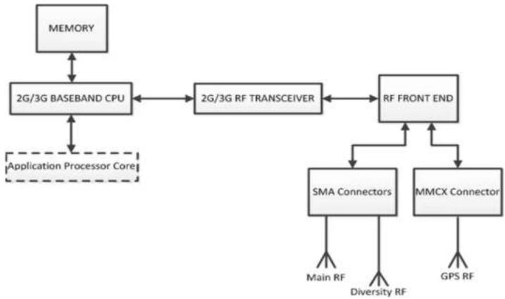
flowchart
graph TD
    A["MEMORY"] --> B["2G/3G BASEBAND CPU"]
    B <--> C["2G/3G RF TRANSCEIVER"]
    C <--> D["RF FRONT END"]
    D <--> E["SMA Connectors"]
    D <--> F["MMCX Connector"]
    E --> G["Main RF"]
    E --> H["Diversity RF"]
    F --> I["GPS RF"]
    J["Application Processor Core"] -.-> B
Figure 2. RF Architecture
1.3. Operating System
The modem is Open AT Application Framework compliant. With the Courier M2M Open AT application loaded, the modem becomes a solution for many specific
2. Technical Specifications
2.1. Power Supply
The modem is supplied by an external DC voltage, DC-IN, with a voltage range of +4.75V to +32V.
The main regulation is made with an internal DC/DC converter in order to supply all the internal functions with a DC voltage. The correct operation of the modem in Communication mode is not guaranteed if the input voltage falls below 4.75V.
Refer to the following table for the modem's operating voltage range and maximum current.
Table 1. Power Supply Electrical Characteristics
| Operating Voltage Range | • 4.75V to 32V DC, nominal at 13.2V |
| Maximum Current (Typical) | • 850mA, average at 4.75V; 3.7A Peak at 4.75V |
The modem is permanently powered once the power supply is connected. In the case of Alarm mode (Low Power mode), the user can set the modem "Turn-on" time. Refer to section 4.1 Alarm Mode for more information.
Caution:
The minimum input voltage specified here is the modern input. Be mindful of the input voltage decrease caused by the power cable. When using the optional 6-wire cable accessory, this input drop is at around 800mV at 4.75V and 220mV at 32V (EDGE 4TX).
The modem is designed for use with the original power cable, and the fuse that came with the original cable is a 2A/250V Slow Break fuse 5.2mm*20mm.
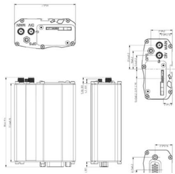
2.2. Mechanical Specifications
3. Interfaces
This section describes the different interfaces that connect with the USR3500. The modem comes with the following interfaces:
• 10-pin Micro-Fit Connector
• USB Interface (mini-B connector)
• 15-pin Sub-D Serial Interface
- Main RF Interface
• Secondary RF Interface
- GPS RF Interface
- SIM Interface
• LED Status Indicator
3.1. Front Interface
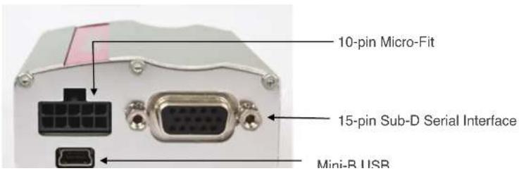
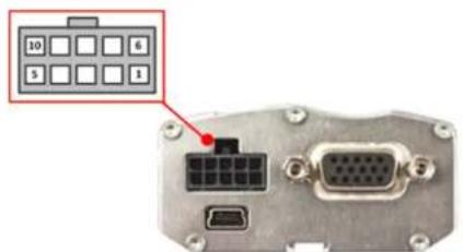
Figure 5. Power Supply Connector
Refer to the following table for the pin description of the power supply connector.
Table 2. Power Supply Connector Pin Description
| Pin # | Signal | Description |
| 1 | GPIO25/INT1 | General purpose input/output or Interrupt |
| 2 | GPIO35 | General purpose input/output |
| 3 | Vref | Voltage reference for the GPIOs |
| 4 | Reserved | Reserved |
| 5 | Reserved | Reserved |
| 6 | GND | Ground |
| 7 | DC-IN | Input Supply for the modem (4.75V to 32V) |
| 8 | ON/OFF | Control pin to power OFF the modem |
| 9 | Reserved | Reserved |
| 10 | Reserved | Reserved |
The input voltage range (DC-IN) is from 4.75V to 32V, with a typical operating
Refer to the following table for the pin description of the GPIOs.
Table 3. GPIO Pin Description
| Pin # | Signal | I/O | I/O Voltage | Description |
| 1 | GPIO25/INT 1 | I/O | Vref | General purpose input/output or interrupt |
| 2 | GPIO35 | I/O | Vref | General purpose input/output |
| 3 | Vref | I | 2.8V ~ 15V | Voltage reference for the GPIOs |
Note: It is recommended to use a 6-wire cable accessory for easy access to these three lines. Please refer to the Getting Started Guide at http://www.usr.com/support/3500 for more information about the 6-wire cable accessory.
When the voltage reference, Vref, is not connected, if one of the GPIO output is in High state while the other is in Low state, the GPIO in high level voltage will be at 2.3V. To avoid this voltage drop, it is recommended to use Vref to the desired output voltage.
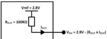
With Vref connected to 2.8V, both GPIO35 and GPIO25 may be interfaced with a component that complies with the following levels.
Table 4. GPIO Pin Operating Conditions when Vref is at 2.8V
| Parameter | Minimum | Typical | Maximum | Condition |
| V_L | 0.84V | Please refer to Figure 6. | ||
| V_H | 1.96V | Please refer to Figure 7. | ||
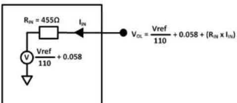
| V_OL | 0.4* | Please refer to Figure 8. | ||
| V_OH | 2.8* | modem Zout = 100K Pull-up to Vref, please refer to Figure 9. |
• Value without external load.
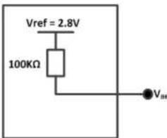
Figure 7. Equivalent Circuit of V, Vref = 2.8V
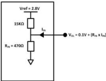
Figure 8. Equivalent Circuit of V _0 Vref = 2.8V
Reference Guide
Interfaces
Value without external load.

Figure 10. Equivalent Circuit of V, Vref > 2.8V
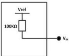
Figure 11. Equivalent circuit of V_ref > 2.8V
- Act as a status reading when the GPIO is configured as input.
The GPIOs may be controlled with the following AT commands:
- AT+WIOW for write access to the GPIO value, when the GPIO is used as an output
- AT+WIOR for read access to the GPIO value, when the GPIO is used as an input
[1] By default, and when the modem has been reset, both GPIOs are configured as inputs. The AT command AT+WIOM must be used to change this configuration. Refer to documents [3] AT Commands Interface Guide
[2] Customer Release Notes for Firmware 7.52 A1
for more information regarding this AT command.
3.1.1.1.1. Setting the GPIO as an Output
Refer to the following example for how to configure the GPIO as an output.
- Enter the following commands:
- AT+WIOM=1, "GPIO21", 1,0 → this command activates GPIO21 as an output and sets it at a low level.
- AT+WIOW="GPIO21",1 level of GPIO21 to HIGH. → this command sets the output
3.1.1.1.2. Setting the GPIO as an Input
3.1.1.2. ON/OFF Pin
The modem has an external ON/OFF pin which is used to turn the device ON or OFF. The following table describes the operation of this pin.
Table 6. ON/OFF Pin Operation
| Condition | State | Power Supply | Operation |
| 1 | Open | When 4.75V to 32V supply is applied. | The modem is turned ON. |
| 2 | Pulled to GND | When 4.75V to 32V supply is applied. | The modem remains OFF. |
| 3 | Left open when turning ON the modem, then pulled to GND | 4.75V to 32V supply is initially applied. | The modem remains ON and will remain ON until AT+CPOF is sent to turn the device OFF. |
To enable the low power mode, the user may simply pull the ON/OFF pin to GND and send AT+CPOF to the modem using a communication software such as a HyperTerminal.
Table 7. ON/OFF Pin Description
| Pin # | Signal | I/O | I/O Voltage | Description |
| 8 | ON/OFF | I | 4V | Pin to turn the modem ON/OFF. |
Refer to the power consumption tables in section 6 Power Consumption for the power consumption values when the modem is in Alarm mode (Low Power mode).
240 Serial Interface
Refer to the following table for the pin description of the 15-pin serial connector.
Table 8. Serial Connector Pin Description
| Pin # | Signal | I/O | I/O Type | Reset State | Description |
| 1 | CT109/DCD | O | +/- 5.5V | Undefined | Data Carrier Detect |
| 2 | CT103/TXD | I | +/- 5.5V | Z | Transmit Serial Data |
| 3 | Reserved | Do not connect | |||
| 4 | CMIC2P | I | Analog | Microphone positive input | |
| 5 | CMIC2N | I | Analog | Microphone negative input | |
| 6 | CT104/RXD | O | +/- 5.5V | 1 | Receive Serial Data |
| 7 | CT107/DSR | O | +/- 5.5V | Z | Data Set Ready |
| 8 | CT108-2/DTR | I | +/- 5.5V | Z | Data Terminal Ready |
| 9 | GND | GND | Ground | ||
| 10 | CSPK2P | O | Analog | Speaker positive input | |
| 11 | CT106/CTS | O | +/- 5.5V | Z | Clear To Send |
| 12 | CT105/RTS | I | +/- 5.5V | Z | Request To Send |
| 13 | CT125/RI | O | +/- 5.5V | Undefined | Ring Indicator |
| 14 | RESET | I/O | 1V8 | Modem Reset | |
| 15 | CSPK2N | O | Analog | Speaker negative input |
3.1.2.1. RS232 Serial Link Connection
Also known as the main serial link, the RS232 interface performs the voltage level adaptation (V24/CMOS V24/V28) between the internal modem (DCE) and external applications (DTE).
The signals available on the RS220 serial link are as follows:

flowchart
graph LR
    A["DCE"] --> B["CT103/TXD"]
    A --> C["CT104/RXD"]
    A --> D["CT105/RTS"]
    A --> E["CT106/CTS"]
    A --> F["CT107/DSR"]
    A --> G["CT108-2/DTR"]
    A --> H["CT109/DCD"]
    A --> I["CT125/RI"]
    J["DTE"] --> K["CT103/TXD"]
    J --> L["CT104/RXD"]
    J --> M["CT105/RTS"]
    J --> N["CT106/CTS"]
    J --> O["CT107/DSR"]
    J --> P["CT108-2/DTR"]
    J --> Q["CT109/DCD"]
    J --> R["CT125/RI"]
Figure 15. RS232 Serial Link Signals
The RS232 interface has been designed to allow flexibility in the use of the serial interface signals. However, the use of TXD, RXD, CTS and RTS signals are mandatory; while the use of DTR, DSR, DCD and RI signals are optional.
Tip:
The modem is designed to operate using all serial interface signals and it is recommended to use CT105/RTS and CT106/CTS for hardware flow control in order to avoid data corruption during transmission.
The USR3500 also implements the Serial Port Auto Shut Down feature with the DTR signal. It is recommended to use the CT108-2/DTR signal to benefit from the current consumption improvement performed by this feature.
3.1.2.2. RS232 Implementation
The following subsections describe how the RS232 serial link can be implemented to suit different designs.
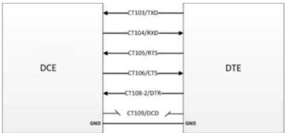
31221 5-wire Serial Interface RS232 Implementation
flowchart
graph LR
    A["DCE"] --> B["CT103/TXD"]
    A --> C["CT104/RXD"]
    A --> D["CT105/RTS"]
    A --> E["CT106/CTS"]
    A --> F["CT108-2/DTR"]
    A --> G["CT109/DCD"]
    H["DTE"] --> I["GND"]
    H --> J["GND"]
Figure 16. V24 Serial Link Implementation for a 5-wire UART
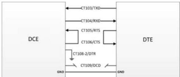
3.1.2.2.2. 4-wire Serial Interface RS232 Implementation
The signals used in this interface are as follows:
- CT103/TXD
- CT104/RXD
- CT105/RTS
- CT106/CTS

flowchart
graph LR
    A["DCE"] --> B["CT103/TXD"]
    A --> C["CT104/RXD"]
    A --> D["CT105/RTS"]
    A --> E["CT106/CTS"]
    A --> F["CT108.2/DTB"]
    G["DTE"] --> H["CT103/TXD"]
    G --> I["CT104/RXD"]
    G --> J["CT105/RTS"]
    G --> K["CT106/CTS"]
    G --> L["CT108.2/DTB"]
flowchart
graph TD
    A["DCE"] --> B["CT103/TXD"]
    A --> C["CT104/RXD"]
    A --> D["CT105/RTS"]
    A --> E["CT106/CTS"]
    A --> F["CT108-2/DTR"]
    A --> G["CT109/DCD"]
    H["DTE"] --> I["GND"]
    H --> J["GND"]
Figure 18. V24 Serial Link Implementation for a 2-wire UART
The CT105/RTS and the CT106/CTS signals are not used in this configuration. Configure the AT command AT+IFC=0,0 to disable the flow control function. Refer to the AT Commands Interface Guide at http://www.usr.com/support/3500 for more information regarding AT Commands.
For more information on how to use the RS232 serial link to communicate with the modem, refer to section 3.1.2.1 RS232 Serial Link Connection.
3.1.2.3. Autobauding Mode
The autobauding mode allows the modem to detect the baud rate used by the DTE connected to the RS232 serial link. The autobauding mode is controlled by AT commands. Refer to the AT Commands Interface Guide at http://www.usr.com/support/3500 for more information.
3.1.2.4. Serial Port Auto Shut Down Feature
3.1.2.5. Audio Lines Connection
The modem supports one microphone input and one speaker output.
3.1.2.5.1. Microphone
The microphone inputs are connected in differential mode to reject common mode noise and TDMA noise. The microphone inputs have already included biasing for an electret microphone (0.5mA and 2V) and are ESD protected. An electret microphone may be directly connected to these inputs allowing an easy connection to a headset.
The microphone gain can be adjusted by AT+VGT and the transmit digital gain can be adjusted by AT+WDGT. Refer to documents the AT Commands Interface Guide at http://www.usr.com/support/3500 for more information about these AT commands.
The following table shows the pin assignments of the microphone input.
Table 9. Microphone Pin Description for USR3500
| (Sub D 15-pin) Pin # | Signal | I/O | I/O Type | Description |
| 4 | CMIC1P | I | Analog | Microphone positive input |
| 5 | CMIC1N | I | Analog | Microphone negative input |
Table 10. Equivalent Circuits of CMIC
| DC Equivalent Circuit | AC Equivalent Circuit |
 | CMICxP Z |
The input voltage depends on the input micro gain set by AT command. Refer to the AT Commands Interface Guide at http://www.usr.com/support/3500.
** Because CMICxP is internally biased, it is necessary to use a coupling capacitor to connect an audio signal provided by an active generator. Only a passive microphone can be directly connected to the CMICxP and CMICxN inputs.
Refer to the following table for the list of recommended microphone characteristics.
Table 12. Recommended Microphone Characteristics
| Feature | Values |
| Type | Electret 2V/0.5 mA |
| Impedance | Z = 2k |
| Sensitivity | -40dB to -50dB |
| SNR | >50dB |
| Frequency response | Compatible with GSM specifications |
3.1.2.5.2. Speaker
The speaker outputs are connected in differential mode to reject common mode noise and TDMA noise.
Speaker outputs are connected to internal push-pull amplifiers and may be loaded down with components between 32 – 150Ω and up to 1nF. These outputs may be directly connected to a speaker.
The output power may be adjusted by 2dB steps. The gain of the speaker outputs is internally adjusted and may be tuned using the AT+VGR command. Furthermore, the digital gain can be adjusted using AT+WDGR. Refer to the AT Commands Interface Guide at http://www.usr.com/support/3500 for more information about these AT commands.
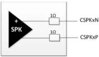
Figure 19. Equivalent Circuit of CSPK
Table 14. Electrical Characteristics of CSPK for USR3500
| Parameters | Min | Typ | Max | Unit | |
| Biasing voltage | CSPKxP and CSPKxN | -1.5 | 1.5 | mV | |
| Output swing voltage | RL=16Ω; AT+VGR=-1600°; single-ended | - | 1.7 | Vpp | |
| RL=32Ω; AT+VGR=-1600°; single-ended | - | 1.9 | 2.75 | Vpp | |
| RL | Load resistance | 14.5 | 32 | - | Ω |
| IOUT | Output current; peak value; RL=16Ω | - | 40 | 85 | mA |
| Output current; peak value; RL=32Ω | - | 22 | - | mA | |
| POUT | RL=16Ω; AT+VGR=-1600° | - | 25 | - | mW |
| RL=32Ω; AT+VGR=-1600° | - | 16 | 27 | mW | |
| RPD | Output pull-down resistance at power-down | 28 | 40 | 52 | kΩ |
The output voltage depends on the output speaker gain set by AT command. Refer to the AT Commands Interface Guide at http://www.usr.com/support/3500. This value is given in dB, but it's possible to toggle this to index value.
Refer to the following table for the list of recommended speaker characteristics.
3.1.3. USB Interface
Aside from the serial interface, the Mini-B USB interface (USB slave) may also be used to directly communicate with the modem.
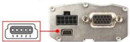
Figure 20. Mini-B USB Connector
Refer to the following table for the pin description of the mini-B USB connector.
Table 16. Mini-B USB Pin Description
| Pin # | Signal | Description |
| 1 | VBUS | +5V Power supply |
| 2 | D- | Differential data interface negative |
| 3 | D+ | Differential data interface positive |
| 4 | ID | Not connected |
| 5 | GND | Ground |
The USR3500 USB slave interface complies with USB 2.0 protocol signaling and with USB 2.0 electrical interface.
The USB interface features:
| Parameter | I/O | Min | Typ | Max | Unit |
| Input Low | 0 | 0.01 | V | ||
| Output High | 0.36 | 0.38 | 0.44 | V | |
| Output Low | 0 | 0.01 | V |
The USB feature can be activated by using the AT+WMFM=0,1,3 AT command. Refer to the AT Commands Interface Guide at http://www.usr.com/support/3500 for more information regarding this AT command.
3.2. Back Interface
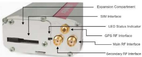
Figure 21. USR3500 Back Interface
3.2.1. SIM Interface
A SIM card can be directly connected to the USR3500 through the embedded SIM socket. This interface controls 3V / 1V8 SIM cards and it is fully compliant with GSM
3.2.1.1. SIM Socket Pin Description
Refer to the following table for the pin description of the SIM socket.
Table 18. SIM Socket Pin Description
| Pin # | Signal | I/O | I/O Type | Reset State | Description |
| 1 | SIMVCC | O | 2V9 / 1V8 | SIM Power Supply | |
| 2 | SIMRST | O | 2V9 / 1V8 | O | SIM RESET |
| 3 | SIMCLK | O | 2V9 / 1V8 | O | SIM Clock |
| 7 | SIMDATA | I/O | 2V9 / 1V8 | Pull up* | SIM DATA |
| 8 | SIMPRES | I | 1V8 | Pull low** | SIM Card Detect |
* SIM-IO pull up is about 10KΩ.
** SIMPRES pull low is about 100KΩ.
3.2.2. RF Interface
The USR3500 has three RF interfaces. Refer to the following table for the list of available RF interfaces.
Table 19. Available RF Interfaces
| Main RF Interface | Secondary RF Interface | GPS RF Interface |
| √ | √ | √ |
The main antenna connector allows the transmission of radio frequency (RF) signals from the device to an external customer supplied antenna. This interface is an SMA
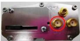
natural_image
Close-up of a metallic electronic component with multiple gold connectors and screw holes (no visible text or symbols)Figure 23. Secondary RF Connector for USR3500
The GPS RF interface is used for GPS antenna connection. It is an MMCX type connector and its nominal impedance is 50Ω. It also provides bias for active antenna. For more details, refer to section 3.2.2.3.6 Active GPS Antenna Bias.
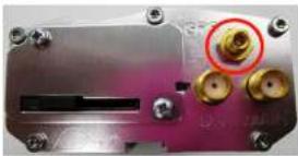
natural_image
Close-up of a metallic electronic device with multiple gold connectors and a red circle highlighting a specific component (no visible text or symbols)Figure 24. GPS RF Connector for USR3500
3.2.2.1. RF Performances
RF performances are compliant with ETSI recommendation GSM 05.05. Refer to the tables below for the main parameters used for both the Receiver and the Transmitter.
Table 20. Main Receiver Parameters for USR3500
| Parameters | Typical Values |
| GSM850 Reference Sensitivity | -108dBm |
| E-GSM900 Reference Sensitivity | -109dBm |
| Output power at PCL19 (EGSM & GSM850) | 5dBm |
| Output power at PCL15 (GSM1800 & PCS1900) | 0dBm |
| Output power Class 3 (3G all band) | 23dBm |
3.2.2.2. Antenna Specifications
The main/secondary antenna must meet the requirements specified in the table below.
The optimum operating frequency depends on the application. A dual-band or quad-band antenna should operate in these frequency bands and have the following characteristics.
Antennas used with the USR3500 must have a maximum antenna gain of 1 dBi for Bands 900 and 1800, and 2.5 dBi for Band 2100.
Table 22. Antenna Specifications for USR3500
| Characteristics | GSM850 and WCDMA Band V | WCDMA Band VI | EGSM 900 and WCDMA Band VIII | DCS 1800 | PCS 1900 and WCDMA Band II | WCDMA Band I | |
| TX Frequency | 824 to 849 MHz | 830 to 840 MHz | 880 to 915 MHz | 1710 to 1785 MHz | 1850 to 1910 MHz | 1920 to 1980 MHz | |
| RX Frequency | 869 to 894 MHz | 875 to 885 MHz | 925 to 960 MHz | 1805 to 1880 MHz | 1930 to 1990 MHz | 2110 to 2170 MHz | |
| Impedance | 50Ω | ||||||
| VSWR | Rx max | 1.5:1 | |||||
| Tx max | 1.5:1 | ||||||
The USR3500 GPS antenna must meet the requirements specified in the table below.
Table 23. GPS Antenna Specifications for USR3500
| Characteristic | GPS L1 | |
| RX Frequency | 1575.42 MHz | |
| RF Impedance | 50Ω | |
| VSWR | Rx max | 1.5:1 |
| LNA Bias Voltage | 5V | |
| LNA Current Consumption | 40mA MAX | |
| Polarization | Linear, vertical | |
| Typical radiated gain | 0dBi in one direction at least | |
3.2.2.3. GPS Specifications for USR3500
Note: These specifications are preliminary targets that are subject to change without notice. Actual GPS functionality depends on the firmware version and module configuration.
The USR3500 provides the GPS features listed in the following sub-sections. This GPS feature can be used through AT commands provided by the Extended Open AT application (which is pre-loaded at the factory) or from a custom Open AT application using Location Library.
3.2.2.3.1. Standalone GPS
- Leading standalone/autonomous GPS performance
Reference Guide
Interfaces
- Best if downloaded once every 1–2 days, but valid for up to 7 days with some accuracy degradation
3.2.2.3.3. A-GPS Features
• Leading A-GPS performance
Exceeds 3GPP RAN 4 AGPS performance specification
- -153 dBm cold start sensitivity
- -155 dBm tracking sensitivity
• <5 second average cold start TTFF in open sky (UE-based)
- < 3 second average super hot TTFF in open sky
- < 2 m accuracy in open sky 1 Hz tracking with CEP-50
• UMTS Control Plane (CP) – UE-assisted and UE-based
• GSM Control Plane (CP) – UE-assisted and UE-based
3.2.2.3.4. Enhanced Navigation 2.0 Feature
- Provides leading performance in car and walking navigation modes as well as accuracy while stationary
• Airline/Game/Offline mode
• GPS capability is available while phone is offline
3.2.2.3.5. NMEA
Supported sentences: GGA, GSA, GSV, RMC, VTG
3.2.2.3.6. Active GPS Antenna Bias
The USB3500 provides bias for active antenna, which can be enabled or disabled.
4. Signals and Indicators
4.1. Alarm Mode
The USR3500 can be turned on using the Alarm mode when power supply is applied. The USR3500 will remain in Low Power mode until the alarm is triggered to start the USR3500 up.
| Note: | Refer to section 3.1.1.2 ON/OFF Pin for more information on how to turn the USR3500 ON or OFF using the ON/OFF pin. |
Table 24. Alarm Mode (Low Power Mode)
| Steps | State | Power Supply | Operation |
| 1 | AT+CALA="YY/MM/DD,H H:MM" | 4.75V to 32V supply is applied. | The alarm is set.The USR3500 remains ON. |
| 2 | Pulled ON/OFF PIN to GND | 4.75V to 32V supply is applied. | The USR3500 remains ON. |
| 3 | AT+CPOF | 4.75V to 32V supply is applied. (The ON/OFF signal remains at GND.) | The USR3500 turns OFF and will remain OFF until the Alarm mode is activated to turn the device ON. |
Note: The USR3500' clock must be set before Alarm mode is activated. To set the clock, refer to the AT+CCLK command in the AT Commands Interface Guide at http://www.usr.com/support/3500.
4.2. RESET Signal Connection
This signal is used to force a reset procedure by providing the USR3500 with a LOW
- ... It is the best, it is the 2000... /k... the ...
Table 25. USR3500 Reset Status
| (Serial Port) Pin # | Signal | I/O | I/O Type | Voltage | Description |
| 14 | Reset | I/O | Open drain | 1V8 | USR3500 Reset |
Table 26. Reset Electrical Characteristics for USR3500
| Parameter | Minimum | Typical | Maximum | Unit |
| Input Impedance (R)* | 10 | kΩ | ||
| Input Impedance (C) | 20 | nF |
* Internal pull-up
Table 27. Reset Operating Conditions
| Parameter | Minimum | Typical | Maximum | Unit |
| -Reset time (Rt)^1 | 200 | s | ||
| -Reset time (Rt)^2 (at power up only) | 20 | 40 | 100 | ms |
| Cancellation time (Ct) | 34 | ms | ||
| V_H' | 0.57 | V | ||
| V_L | 0 | 0.57 | V | |
| V_H | 1.33 | V |
* V _H = Hysterisis Voltage
1: This reset time is the minimum to be carried out on the \~Reset signal when the power supply is stabilized.
2: This reset time is internally carried out by the embedded module power supply supervisor only when the embedded module power supplies are powered ON.
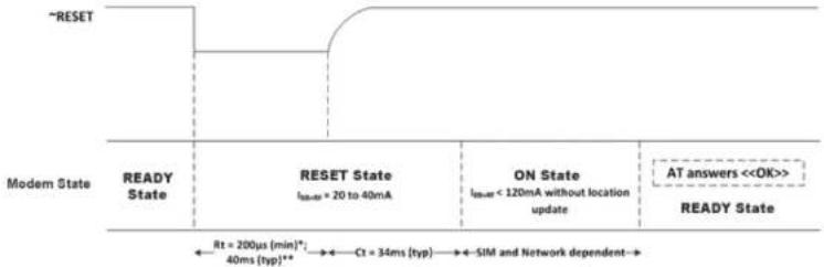
4.2.1. Reset Sequence
To activate the Reset sequence, the Reset signal has to be set to LOW for a minimum of 200 s. As soon as the reset is done, the application can send the command AT← and the AT interface will send an "OK" back to the application. If the application manages hardware flow control, the AT command may be sent during the initialization phase.
flowchart
graph LR
    A["~RESET"] --> B["ReeY State"]
    B --> C["RESET State\nIcc=20 to 40mA"]
    C --> D["ON State\nIcc=120mA without location update"]
    D --> E["AT answers <<OK>>"]
    E --> F["READY State"]
    style A fill:#f9f,stroke:#333
    style B fill:#ccf,stroke:#333
    style C fill:#cfc,stroke:#333
    style D fill:#fcc,stroke:#333
    style E fill:#ffc,stroke:#333
    style F fill:#cff,stroke:#333
* This reset time is the minimum time to be carried out on the "RESET signal when the power supply is already stabilized.
** This reset time is internally carried out by the power supply supervisor only when the modem power supplies are powered ON.
Figure 25. Reset Sequence Diagram
Another solution is to use the AT+WIND command to get an unsolicited status from the USR3500. Refer to the AT Commands Interface Guide at http://www.usr.com/support/3500 for more information regarding AT commands.
4.3. LED Status Indicator
The USR3500 has a red LED that indicates the current operational status of the
The Flash LED can be disabled by the user when in Sleep mode in order to save power consumption. Refer to the AT Commands Interface Guide at http://www.usr.com/support/3500 for more information on how to disable the Flash LED using an AT command.
4.4. Real Time Clock (RTC)
The USR3500 has implemented Real Time Clock for saving date and time when the USR3500 is unplugged from the DC power supply through the DC power cable.
Table 29. Real Time Clock Specifications
| Item | Minimum | Typical | Maximum | |
| Charging Time start from fully discharged to fully charged | 15 Hours | |||
| RTC Time Period* | Guaranteed | 30 Hours | ||
| Not guaranteed | 60 Hours | |||
This RTC time period is measured when the RTC battery is fully charged before the modem is unplugged from the DC power source.
This RTC time period is for temperature from -20^ to +60^ . Once the operating/storage temperature is beyond this range, this time period is not guaranteed.
Caution: When the modem is shipped out, the charging voltage of the RTC battery is not guaranteed. Once the modem is on power, the RTC battery will start charging and the RTC feature can then be resumed.
4.5. Interrupt
An interrupt pin, INT1, is multiplexed with GPIO25 on pin 1 of the Microfit connector. Additional interrupt pins are also available via the expansion card connector. Refer to the following table for the list of available interrupt pins in the modem.
5. Expansion
5.1. Expansion Compartment
The expansion compartment allows users to easily expand the USR3500's features (Ethernet, for example) for their own applications.
natural_image
Exterior view of a white electronic device with gold connectors and internal components (no visible text or symbols)Figure 26. USR3500 expansion compartment
Refer to the Ethernet Expansion Card User Guide at http://www.usr.com/support/3500 for more information regarding this feature.
6. Power Consumption
The following sub-sections details out the power consumption values of the USR3500 for various modes and RF bands. These consumption values were obtained by performing measurements on USR3500 samples at a temperature of 25^ C using a 3V SIM card.
Note: For power consumption, the software version used is R7.50 A1.
Refer to the Courier M2M Application guide at http://www.usr.com/support/3500 for details on how to upgrade modem firmware.
The table below gives the average power consumption of the USR3500 for the first 10s when power supply (DC-IN, supplied by Agilent 66321D in this example) is initially applied to it with no serial port, LED ON or SIM card at ambient temperature.
Table 31. Initial Power Consumption (Typical)
| Configuration | USR3500 Average Power Consumption with FW R7.50 A1 |
| DC-IN @ 13.2V | 18mA |
6.1. Various Operating Modes
The power consumption levels of the USR3500 vary depending on the operating mode used. Refer to the table below for the different kinds of operating modes available. Refer to Appendix 3.1 of the AT Commands Interface Guide at http://www.usr.com/support/3500 for the working mode description.
| Operating Mode | Description |
| Alarm Mode | Low power consumption mode, the only feature which is available in this mode is the alarm wake up.When the alarm clock is set for the modem withALLof the following conditions:• before the alarm time is up• with the ON/OFF signal pulled to GND• withAT+CPOFentered from a computer that is connected to the modem |
| Serial Port Auto Shut Down Feature | The serial link can be shut down when there is no activity between the DTE and the modem.This auto shut down feature can be enabled by AT command. Refer to section 3.1.2.4 Serial Port Auto Shut Down Feature for more information on this feature. |
| FLASH LED Activated/Deactivated | The modem Flash LED can be enabled or disabled by AT command. Refer to section for more information on this feature. |
6.2. Working Mode Features
The table below sums up the feature availability in each mode.
Table 33. USR3500 Operating Modes Feature Availability
| Features | Alarm Mode | ACTIVE Mode with GSM Stack In Idle | SLEEP Mode with GSM Stack In Idle | ACTIVE Mode | SLEEP Mode | Connected Mode | Transfer Mode |
| Alarm | |||||||
| Wake-up Open AT Application Framework on timer events | - |
6.3. Connected Mode Power Consumption
Table 34. Power Consumption of USR3500 in Connected Mode with Serial Port OFF, Flash LED OFF and USB ON (typical values)
| Mode | Parameters | I_average | I_peak | Unit | ||||
| DC-IN=4.75V | DC-IN=13.2V | DC-IN=32V | DC-IN=4.75V | DC-IN=13.2V | ||||
| GSM | 850 MHz | PCL5 (TX power 33dBm) | 420 | 107 | 46 | 3625 | 703 | mA |
| PCL19 (TX power 5dBm) | 97 | 34 | 15 | 682 | 249 | mA | ||
| 900 MHz | PCL5 (TX power 33dBm) | 428 | 109 | 47 | 3782 | 710 | mA | |
| PCL19 (TX power 5dBm) | 99 | 35 | 15 | 698 | 215 | mA | ||
| 1800 MHz | PCL0 (TX power 30dBm) | 299 | 91 | 39 | 2374 | 536 | mA | |
| PCL15 (TX power 0dBm) | 101 | 35 | 16 | 728 | 226 | mA | ||
| 1900 MHz | PCL0 (TX power 30dBm) | 269 | 86 | 37 | 2169 | 497 | mA | |
| PCL15 (TX power 0dBm) | 102 | 36 | 16 | 813 | 255 | mA | ||
| GPRS class 8(1TX,4RX) | 850 MHz | PCL5 (gamma 3) | 363 | 102 | 45 | 3478 | 702 | mA |
| 900 MHz | PCL5 (gamma 3) | 384 | 107 | 42 | 3600 | 720 | mA | |
| 1800 MHz | PCL0 (gamma 3) | 291 | 84 | 38 | 2413 | 538 | mA | |
| 1900 MHz | PCL0 (gamma 3) | 253 | 83 | 36 | 2008 | 486 | mA | |
| GPRS class 10(2TX,3RX) | 850 MHz | PCL5 (gamma 3) | 654 | 174 | 76 | 3503 | 880 | mA |
| 900 MHz | PCL5 (gamma 3) | 698 | 185 | 78 | 3489 | 1001 | mA | |
| 1800 MHz | PCL0 (gamma 3) | 476 | 143 | 61 | 2348 | 910 | mA | |
| 1900 MHz | PCL0 (gamma 3) | 459 | 129 | 58 | 2201 | 833 | mA | |
| GPRS class 12(4TX,1 RX) | 850 MHz | PCL5 (gamma 3) | 467 | 147 | 72 | 1414 | 749 | mA |
| 900 MHz | PCL5 (gamma 3) | 519 | 180 | 75 | 1510 | 787 | mA | |
| 1800 MHz | PCL0 (gamma 3) | 553 | 184 | 78 | 1587 | 794 | mA | |
| 1900 MHz | PCL0 (gamma 3) | 570 | 183 | 76 | 1598 | 801 | mA | |
Reference Guide
Power Consumption
| Mode | Parameters | l_average | l_peak | Unit | ||||
| DC-IN=4.75V | DC-IN=13.2V | DC-IN=32V | DC-IN=4.75V | DC-IN=13.2V | ||||
| UMTS(Voice) | Band I | +22 dBm | 637 | 222 | 94 | 1090 | 767 | mA |
| +10 dBm | 227 | 81 | 34 | 1057 | 442 | mA | ||
| Band II | +22 dBm | 616 | 210 | 88 | 1074 | 830 | mA | |
| +10 dBm | 232 | 80 | 35 | 1062 | 423 | mA | ||
| Band V | +22 dBm | 606 | 204 | 89 | 1042 | 898 | mA | |
| +10 dBm | 204 | 70 | 31 | 842 | 417 | mA | ||
| Band VI | +22 dBm | 609 | 204 | 88 | 1036 | 858 | mA | |
| +10 dBm | 200 | 71 | 30 | 978 | 404 | mA | ||
| Band VIII | +22 dBm | 582 | 200 | 87 | 1050 | 895 | mA | |
| +10 dBm | 328 | 114 | 51 | 804 | 646 | mA | ||
| UMTS(Data Transfer 2) 384 kbit/s | Band I | +22 dBm | 694 | 225 | 97 | 585 | 781 | mA |
| +10 dBm | 243 | 85 | 42 | 987 | 457 | mA | ||
| Band II | +22 dBm | 798 | 226 | 107 | 1306 | 899 | mA | |
| +10 dBm | 250 | 89 | 38 | 1121 | 481 | mA | ||
| Band V | +22 dBm | 628 | 208 | 90 | 1095 | 961 | mA | |
| +10 dBm | 206 | 73 | 33 | 1117 | 430 | mA | ||
| Band VI | +22 dBm | 669 | 221 | 92 | 1133 | 827 | mA | |
| +10 dBm | 216 | 76 | 32 | 1170 | 406 | mA | ||
| Band VIII | +22 dBm | 594 | 201 | 87 | 1045 | 1003 | mA | |
| +10 dBm | 330 | 118 | 52 | 810 | 708 | mA | ||
| HSDPA Data | Band I | +22 dBm | 736 | 243 | 103 | 1155 | 754 | mA |
| +10 dBm | 314 | 109 | 48 | 747 | 592 | mA | ||
| Band II | +22 dBm | 636 | 213 | 96 | 1032 | 724 | mA | |
| +10 dBm | 322 | 107 | 46 | 703 | 585 | mA | ||
6.4. Non-Connected Mode Power Consumption
Note: The USB port must be deactivated to enter Sleep Mode.
Table 35. Power Consumption of USR3500 in Non-Connected Mode with UART ON, FLASH LED OFF and USB OFF (typical values)
| Mode | Serial Port Status | I_average | Unit | ||
| DC-IN=4.75V | DC-IN=13.2V | DC-IN=32V | |||
| Active Idle Mode, HSPA | ON | 45.82 | 16.56 | 7.6 | mA |
| OFF | 15.48 | 5.96 | 2.81 | mA | |
| Sleep Idle Mode, HSPA | ON | 32.66 | 11.89 | 5.8 | mA |
| OFF | 3.09 | 1.39 | 0.78 | mA | |
| Active Idle Mode, 2G page 9 | ON | 46.01 | 16.47 | 7.5 | mA |
| OFF | 16.43 | 6.01 | 2.96 | mA | |
| Sleep Idle Mode, 2G page 9 | ON | 31.91 | 11.51 | 5.65 | mA |
| OFF | 2.7 | 1.12 | 0.81 | mA | |
| Active Idle Mode, 2G page 2 | ON | 47.11 | 16.82 | 7.75 | mA |
| OFF | 17.54 | 6.4 | 3.15 | mA | |
| Sleep Idle Mode, 2G page 2 | ON | 33.51 | 12.07 | 5.65 | mA |
| OFF | 4.3 | 1.64 | 1.14 | mA | |
| Alarm Mode | OFF | 2.7 | 1.23 | 0.91 | mA |
7. Recommendations when Using the USR3500 on Trucks
Caution: The power supply connection of the modem must never be directly connected to the truck battery.
7.1. Recommended Power Supply Connection on Trucks
All trucks have a circuit breaker on the exterior of the cabin. The circuit breaker is used for safety reasons: if a fire blazes in the trucks, (for example, on the wiring trunk) the driver may cut the current source to avoid any damage (explosion). The circuit breaker is connected to the truck ground, most often associated with the fuse box. Most truck circuit breakers do not cut the Positive Supply line of the battery, but cut the ground line of the latter.
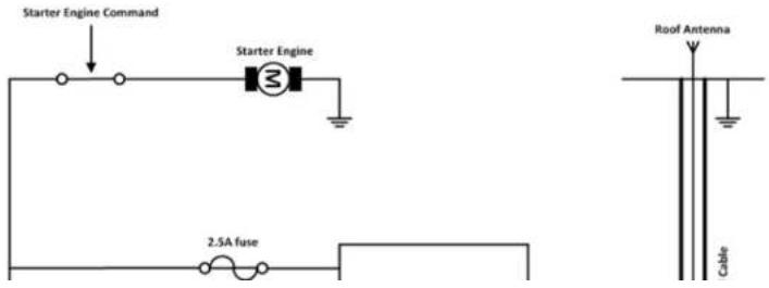
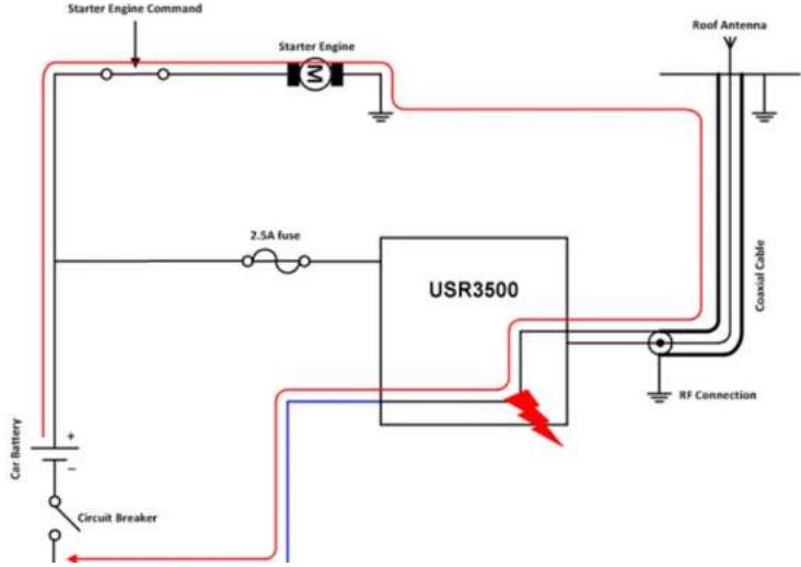
7.2. Technical Constraints on Trucks
It is highly recommended to directly connect the power supply on the circuit breaker rather than on the battery. The modem may be damaged when starting the truck if the circuit breaker is switched OFF (in this case, the truck ground and the battery ground will be connected through the modem as shown in the following figure).
8. Reliability Compliance and Recommended Standards
8.1. Reliability Compliance
The USR3500 is compliant with the following requirements.
Table 36. Standards Conformity for the modem
| Abbreviation | Definition |
| IEC | International Electro technical Commission |
| ISO | International Organization for Standardization |
8.2. Applicable Standards Listing
The table hereafter gives the basic list of standards applicable to the USR3500.
Note: References to any features can be found from these standards.
Table 37. Applicable Standards and Requirements for the modem
| Document | Current Version | Title |
| IEC6006826 | 7.0 | Environmental testing - Part 2.6: Test FC: Sinusoidal Vibration. |
| IEC60068234 | 73 | Basic environmental testing procedures part 2: Test FD: random vibration wide band - general requirements. |
| IEC60068238 | 2.0 | Environmental testing - part 2-38: Test Z/AD: composite temperature/humidity cyclic test. |
| IEC60068240 | 1.0 w/A1 | Basic environmental testing procedures - part 2: Test Z/AM combined cold/low air pressure tests. |
| ISO167501 | 2ND | Road vehicles - environmental conditions and testing for electrical and electronic equipment - part 1: general. |
| ISO167502 | 2ND | Road vehicles - environmental conditions and testing for electrical and electronic equipment - part 2: electrical loads. |
| ISO167503 | 2ND | Road vehicles - environmental conditions and testing for electrical and electronic equipment - part 3: mechanical loads. |
| ISO167504 | 2ND | Road vehicles - environmental conditions and testing for electrical and electronic equipment - part 4: climatic loads. |
| IEC60529 | 2.1 w/COR2 | Degrees of protection provided by enclosures (IP code). |
| IEC60068217 | 4.0 | Basic environmental testing procedures - part 2: Test Q: sealing. |
| IEC60068218 | 2.0 | Environmental testing - part 2-18: Tests - R and guidance: water. |
| IEC60068270 | 1.0 | Environmental testing - part 2: tests - test XB: abrasion of markings and letterings caused by rubbing of fingers and hands. |
| IEC60068268 | 1.0 | Environmental testing - part 2: tests - test I: dust and sand. |
| IEC60068211 | 3.0 | Basic environmental testing procedures, part 2: test KA: salt mist. |
| IEC60068260 | 2.0 | Environmental testing - part 2: Test KE: flowing mixed gas corrosion test. |
| IEC60068252 | 2.0 w/COR | Environmental testing - part 2: Test KB: salt mist, cyclic (sodium chloride solution). |
8.3. Environmental Specifications
The USR3500 is compliant with the operating classes listed below. The ideal temperature range of the environment for each operating class is also specified.
8.3.1. Function Status Classification
The classes reported below comply with the Annex “ISO Failure Mode Severity Classification”, ISO Standard 7637, and Section 1.
| Note: | The word “function” used here only concerns the function performed by the modem. |
Table 39. ISO Failure Mode Severity Classification
| Class | Definition |
| CLASS A | All equipment/system functions are fulfilled normally (100% functional) during and after the constraint.The modem shall exhibit normal function during and after environmental exposure. The modem performance shall meet the minimum requirements of 3GPP or appropriate wireless standards. |
| CLASS B | All equipment/system functions are fulfilled normally during application of the constraint; however, one or several of them may be out of the specified tolerances. After application of the constraint, all functions automatically return within standard limits. The memories shall remain in compliance with Class A.The modem shall exhibit the possibility at all times to establish a voice, SMS or DATA call. Unless otherwise stated, full performance should return to normal after the external influence has been removed. |
| CLASS C | No functional requirement will be fulfilled during the application of the constraint; however, full functionality will automatically be returned after the constraint has been removed. |
9. Certification Compliance and Recommended Standards
9.1. Certification Compliance
Refer to the following tables for the requirements compliance of the USR3500.
Table 40. Standards Conformity for USR3500
| Domain | Applicable Standard |
| Safety & Health | IEC 60950:2005+A1:2009EN 60950:2006+A11:2009+A1:2010+A12:2011EN 62311: 2008 |
| Efficient use of the radio frequency spectrum | EN 301 440-1, v1.6.1EN 301 440-2 v1.4.1EN 301 511, v9.0.2EN 301 908-1, v4.2.1EN 301 908-2, v5.2.1 |
| EMC | EN 301 489-1, v1.9.2EN 301 489-3, v1.4.1EN 301 489-7, v1.3.1EN 301 489-24, v1.5.1 |
| FCC | FCC Part 22, 24 |
| IC | RSS-132 Issue 2RSS-133 Issue 5 |
| International Standard for Battery | IEC 61951-2 |
9.2. Applicable Standards Listing
The table hereafter gives the basic list of standards applicable for 2G and 3G (HSPA).
Note: References to any features can be found from these standards.
Table 41. Applicable Standards and Requirements for USR3500
| Document | Current Version | Title |
| GCF-CC | 3.46.0 | GSM Certification Forum-Certification Criteria |
| NAPRD.03 | 5.11 | Overview of PCS Type certification review board (PTCRB) Mobile Equipment Type Certification and IMEI control |
| TS 51.010-1 | 10.1.0 | 3rd Generation Partnership Project; Technical Specification Group GSM/EDGE Radio Access Network; Digital cellular telecommunications system (Phase 2+); Mobile Station (MS) conformance specification; Part 1: Conformance specification |
| TS 51.010-2 | 10.1.0 | 3rd Generation Partnership Project; Technical Specification Group GSM/EDGE Radio Access Network; Mobile Station (MS) conformance specification; Part 2: Protocol Implementation Conformance Statement (PICS) proforma specification |
| TS 51.010-4 | 4.23.0 | 3rd Generation Partnership Project; Technical Specification Group GSM/EDGE Radio Access Network; Digital cellular telecommunications system (Phase 2+); Mobile Station (MS) conformance specification; Part 4: SIM Application Toolkit Conformance specification |
| EN 301 511 | 9.0.2 | Global System for Mobile Communications (GSM); Harmonized standard for mobile stations in the GSM 900 and DCS 1800 bands covering essential requirements under article 3.2 of the R&TTE directive (1999/5/EC) |
| EN 301 908-2 | 5.2.1 | Global System for Mobile Communications (GSM); Harmonized standard for mobile stations in the GSM 900 and DCS 1800 bands covering essential requirements under article 3.2 of the R&TTE directive (1999/5/EC) |
10. Safety Recommendations
10.1. General Safety
For the efficient and safe operation of your programmable modem, please read the following information carefully.
It is important to follow any special regulations regarding the use of radio equipment due in particular to the possibility of radio frequency (RF) interference. Carefully follow the safety advice given.
Switch OFF your programmable modem:
- When in an aircraft. The use of cellular telephones in an aircraft may endanger the operation of the aircraft, disrupt the cellular network and is illegal. Failure to observe this instruction may lead to suspension or denial of cellular telephone services to the offender, or legal action or both,
- When at a refueling point,
- When in any area with a potentially explosive atmosphere which could cause an explosion or fire,
• In hospitals and any other place where medical equipment may be in use.
Respect restrictions on the use of radio equipment in:
- Fuel depots,
- Chemical plants,
- Places where blasting operations are in progress,
There may be a hazard associated with the operation of your USR3500 close to inadequately protected personal medical devices such as hearing aids and pacemakers. Consult the manufacturers of the medical device to determine if it is adequately protected.
Operation of your USR3500 close to other electronic equipment may also cause interference if the equipment is inadequately protected. Observe any warning signs and manufacturers' recommendations.
The USR3500 is designed for and intended to be used in "fixed" and "mobile" applications:
"Fixed" means that the device is physically secured at one location and is not able to be easily moved to another location.
"Mobile" means that the device is designed to be used in other than fixed locations and generally in such a way that a separation distance of at least 20 cm (8 inches) is normally maintained between the transmitter's antenna and the body of the user or nearby persons.
The USR3500 is not designed for nor intended to be used in portable applications (within 20 cm or 8 inches of the body of the user) and such uses are strictly prohibited.
10.2. RF Safety
10.2.1. General
Your GSM modem is based on the GSM standard for cellular technology. The GSM standard is spread all over the world. It covers Europe, Asia and some parts of America and Africa. This is the most used telecommunication standard.
Your GSM modem is actually a low power radio transmitter and receiver. It sends out and receives radio frequency energy. When you use your GSM application, the cellular system which handles your calls controls both the radio frequency and the power level of your cellular modem.
10.2.2. Exposure to RF Energy
There has been some public concern about possible health effects of using GSM modems. Although research on health effects from RF energy has focused on the current RF technology for many years, scientists have begun research regarding newer radio technologies, such as GSM. After existing research had been reviewed, and after compliance to all applicable safety standards had been tested, it has been concluded that the product was acceptable for use.
If you are concerned about exposure to RF energy there are things you can do to minimize exposure. Obviously, limiting the duration of your calls will reduce your exposure to RF energy. In addition, you can reduce RF exposure by operating your cellular modem efficiently by following the below guidelines.
10.2.3. Efficient Modem Operation
that the installation has been performed by qualified personnel. Verification of the protection of vehicle electronics should form part of the installation.
The use of an alert device to operate a vehicle's lights or horn on public roads is not permitted.
10.4. Care and Maintenance
Your USR3500 is the product of advanced engineering, design and craftsmanship and should be treated with care. The suggestion below will help you to enjoy this product for many years.
Do not expose the USR3500 to any extreme environment where the temperature or humidity is high.
Do not use or store the USR3500 in dusty or dirty areas. Its moving parts can be damaged.
Do not attempt to disassemble the modem. There are no user serviceable parts inside.
Do not expose the USR3500 to water, rain or beverages. It is not waterproof.
Do not abuse your USR3500 by dropping, knocking, or violently shaking it. Rough handling can damage it.
Do not place the USR3500 alongside computer discs, credit or travel cards or other magnetic media. The information contained on discs or cards may be affected by the embedded module.
The use of third party equipment or accessories not authorized by USRobotics may invalidate the warranty of the modem.
Contact USRobotics in the unlikely event of a modem failure.
11. Reference Documents
For more details, several reference documents can be consulted. The documents referenced herein are provided by USRobotics. Visit the USRobotics website at http://www.usr.com/ for the latest documentation available.
11.1. Firmware Documentation
[3] AT Commands Interface Guide
[4] Customer Release Notes for Firmware 7.52 A1
11.2. Expansion Card Documentation
[5] Ethernet Expansion Card User Guide
12. List of Abbreviations
| Abbreviation | Definition |
| AC | Alternating Current |
| ACM | Accumulated Call Meter |
| AMR | Adaptive Multi-Rate |
| AT | ATTention (prefix for Wireless CPU ^® commands) |
| CLK | CLocK |
| CMOS | Complementary Metal Oxide Semiconductor |
| CS | Coding Scheme |
| CTS | Clear To Sond |
| dB | Decibel |
| dBc | Decibel relative to the Carrier power |
| dBi | Decibel relative to an Isotropic radiator |
| dBm | Decibel relative to one milliwatt |
| DC | Direct Current |
| DCD | Data Carrier Detect |
| DCE | Data Communication Equipment |
| DCS | Digital Cellular System |
| DSR | Data Set Ready |
| DTE | Data Terminal Equipment |
| DTMF | Dual Tone Multi-Frequency |
| DTR | Data Terminal Ready |
| EEPROM | Electrically Erasable Programmable Read-Only Memory |
| EFR | Enhanced Full Rate |
| E-GSM | Extended GSM |
| IEC | International Electrotechnical Commission |
| IES | Internal Expansion Socket |
| IESM | Internal Expansion Socket Module |
| IMEI | International Mobile Equipment Identification |
| I/O | Input / Output |
| LED | Light Emitting Diode |
| MAX | MAXimum |
| ME | Mobile Equipment |
| MIC | MICrophone |
| Micro-Fit | Family of connectors from Molex |
| MIN | MINimum |
| MNP | Microcom Networking Protocol |
| MO | Mobile Originated |
| MS | Mobile Station |
| MT | Mobile Terminated |
| NOM | NOMinal |
| O | Output |
| Pa | Pascal (for speaker sound pressure measurements) |
| PBCCH | Packet Broadcast Control Channel |
| PC | Personal Computer |
| PCL | Power Control Level |
| PDP | Packet Data Protocol |
| PIN | Personal Identity Number |
| PLMN | Public Land Mobile Network |
| PUK | Personal Unblocking Key |
| RF | Radio Frequency |
DEI
Dadie Eraguanceur Interferances
Reference Guide
List of Abbreviations
| Abbreviation | Definition |
| TYP | TYPical |
| UMTS | Universal Mobile Telecommunications System |
| VSWR | Voltage Standing Wave Ratio |


- Important Notice
- Safety and Hazards
- Reference Guide
- Patents
- Copyright
- Trademarks
- Contents
- RECOMMENDATIONS WHEN USING THE USR3500 ON TRUCKS 48
- RELIABILITY COMPLIANCE AND RECOMMENDED STANDARDS....50
- CERTIFICATION COMPLIANCE AND RECOMMENDED STANDARDS...... 53
- SAFETY RECOMMENDATIONS.... 55
- 11.REFERENCE DOCUMENTS....59
- List of Figures
- List of Tables
- Functional Specifications
- Functional Specifications
- Functional Architecture
- RF Functionalities
- Operating System
- Technical Specifications
- Power Supply
- Mechanical Specifications
- Interfaces
- Front Interface
- Interfaces
- Setting the GPIO as an Output
- Setting the GPIO as an Input
- ON/OFF Pin
- Serial Interface
- RS232 Serial Link Connection
- RS232 Implementation
- 4-wire Serial Interface RS232 Implementation
- Autobauding Mode
- Serial Port Auto Shut Down Feature
- Audio Lines Connection
- Microphone
- Speaker
- USB Interface
- Back Interface
- SIM Interface
- SIM Socket Pin Description
- RF Interface
- RF Performances
- Antenna Specifications
- GPS Specifications for USR3500
- Standalone GPS
- A-GPS Features
- Enhanced Navigation 2.0 Feature
- NMEA
- Active GPS Antenna Bias
- Signals and Indicators
- Alarm Mode
- RESET Signal Connection
- Reset Sequence
- LED Status Indicator
- Real Time Clock (RTC)
- Interrupt
- Expansion
- Expansion Compartment
- Power Consumption
- Various Operating Modes
- Working Mode Features
- Connected Mode Power Consumption
- Non-Connected Mode Power Consumption
- Recommendations when Using the USR3500 on Trucks
- Recommended Power Supply Connection on Trucks
- Technical Constraints on Trucks
- Reliability Compliance and Recommended Standards
- Reliability Compliance
- Applicable Standards Listing
- Environmental Specifications
- Function Status Classification
- Certification Compliance and Recommended Standards
- Certification Compliance
- Applicable Standards Listing
- Safety Recommendations
- General Safety
- RF Safety
- General
- Exposure to RF Energy
- Efficient Modem Operation
- Care and Maintenance
- Reference Documents
- Firmware Documentation
- Expansion Card Documentation
- List of Abbreviations
Brand : USRobotics
Model : Courier USR3500
Category : Router