
Courier USR3513 - Router USRobotics - Free user manual and instructions
Find the device manual for free Courier USR3513 USRobotics in PDF.

| Product Type | Cellular Gateway (Router) |
| Model | Courier USR3513 |
| Dimensions | 5.85 x 4.46 x 1.04 in (14.88 x 11.33 x 2.65 cm) |
| Weight | 0.95 lb (0.43 kg) |
| Power Input | 8 to 12.5 VDC, barrel connector, center positive |
| Power Consumption | 3.6W idle (typical), 5.7W full load (typical) |
| Cellular Interface | 4G LTE Cat 1, HSPA (USR3513); downlink up to 10 Mbps, uplink up to 5 Mbps |
| LAN Interface | 1 RJ45, 10/100 Mbps, auto MDI/MDIX |
| WAN Interface | 1 RJ45, 10/100 Mbps, auto MDI/MDIX |
| Serial Interface | 1 DB9-F, DCE, RS-232 or RS-485; speeds up to 115200 bps |
| VPN Support | IPsec and OpenVPN (site-to-site) |
| Firewall | DMZ, inbound port forwarding, outbound port filtering, trusted IPs |
| LED Indicators | POWER, RSSI, WAN, WAN 10/100, LAN, LAN 10/100 |
| Reset Button | Recessed; reboot or factory reset (hold timing dependent) |
| SIM Slot | 1 slot, 2FF, concealed with screw cover |
| Antenna Connectors | 1 Main and 1 Auxiliary, SMA female, 50 ohm |
| Mounting | Wall-mount flanges or DIN-rail (adaptor not included) |
| Housing Material | Industrial-grade steel |
| Operating Temperature | -10 to 70°C |
| Storage Temperature | -40 to 85°C |
| Regulatory Approvals | FCC, Industry Canada, CE, RoHS, DoE Level VI (USR3513) |
| Warranty | Two-year limited manufacturer warranty |
| Package Contents | Gateway, power supply, two antennas, Ethernet cable, quick start guide |
| Maintenance | Firmware upgrade via web interface; factory reset via button or web |
| Safety Distance | At least 20 cm from human body |
Frequently Asked Questions - Courier USR3513 USRobotics
User questions about Courier USR3513 USRobotics
0 question about this device. Answer the ones you know or ask your own.
Ask a new question about this device
Download the instructions for your Router in PDF format for free! Find your manual Courier USR3513 - USRobotics and take your electronic device back in hand. On this page are published all the documents necessary for the use of your device. Courier USR3513 by USRobotics.
USER MANUAL Courier USR3513 USRobotics
Courier® M2M 4G LTE Cat 1 Cellular Gateway
User Guide
USR3513
USR803513

natural_image
Black USB network device with two external antennas and power ports (no visible text or symbols on body)R24.0806.00
Rev 1.1 4/2019
Contents
INTRODUCTION ....3
Product Overview....4
Package Contents....6
Product Highlights....7
Product Specifications....7
Hardware Features 13
Mounting....17
GETTING STARTED 20
Establishing a Cellular Connection ....20
CONFIGURATION....25
Overview 25
Accessing the Web Interface....25
Navigating the Web Interface 27
Status Page 29
Network Menu 37
Advanced Setup Menu 63
Administrator Menu 84
APPENDIX 102
ASCII Table....102
Creating OpenVPN Certificates & Keys 103
WARRANTY 107
REGULATORY 111
COPYRIGHT 113
INTRODUCTION
Thank you for purchasing the USR Courier M2M 4G LTE Cat 1 Cellular Gateway!
For more than three decades, millions of businesses and consumers have relied on USR for dependable Internet access. Today, USR endeavors to continue the longstanding tradition of supporting successful businesses by providing equipment for data transfer, remote management, broadband backup, point-of-sale, and machine-to-machine

natural_image
Black wireless router device with two external antennas (no visible text or symbols)functions. USR strives to support the latest technologies through the development of new tools, which are known for their mobility, convenience, and reliability. USR products are designed for multiple environments, including data centers, remote networks, embedded solutions, and small-to medium-sized business markets.
This User Guide explains how to set-up and use the Courier M2M 4G LTE Cat 1 Cellular Gateway.
This document pertains to both the USR3513 and the USR803513. In this document, the term “Cellular Gateway” is used when referring to both versions. The terms USR3513 or USR803513 are used when referring to a specific version.
Screenshots and graphics shown in this guide may differ slightly from your product due to differences in your product's firmware, your web browser, or your computer's operating system.
The following topics are covered in this chapter:
• Product Overview
• Package Contents
• Product Highlights
• Product Specifications
- Hardware Features
- LED Indicators
- Reset Button
- Mounting
Product Overview
The Courier M2M 4G LTE Cat 1 Cellular Gateway is a wireless device that provides cellular connectivity to the Internet for machine-to-machine (M2M) and Internet of Things (IoT) applications.
The Cellular Gateway can interface with a wide variety of M2M and IoT equipment via Ethernet or serial port.
For example, the Cellular Gateway can allow remote M2M equipment to wirelessly contact an application server via the Internet and transmit M2M data, as shown in figure 1.

flowchart
graph LR
    A["M2M Equipment"] -->|Ethernet| B["4G/LTE Cellular Network"]
    B --> C["USB3513"]
    C --> D["Internet"]
    D --> E["Application Server"]
figure 1
Also, the Cellular Gateway can allow remote serial equipment to wirelessly contact an application server via the Internet and transmit M2M data, as shown in figure 2.

flowchart
graph LR
    A["M2M Equipment"] -->|USB3513| B["4G/LTE Cellular Network"]
    B --> C["Internet"]
    C --> D["Application Server"]
    style A fill:#f9f,stroke:#333
    style D fill:#bbf,stroke:#333
figure 2
USR3513/USR803513 User Guide
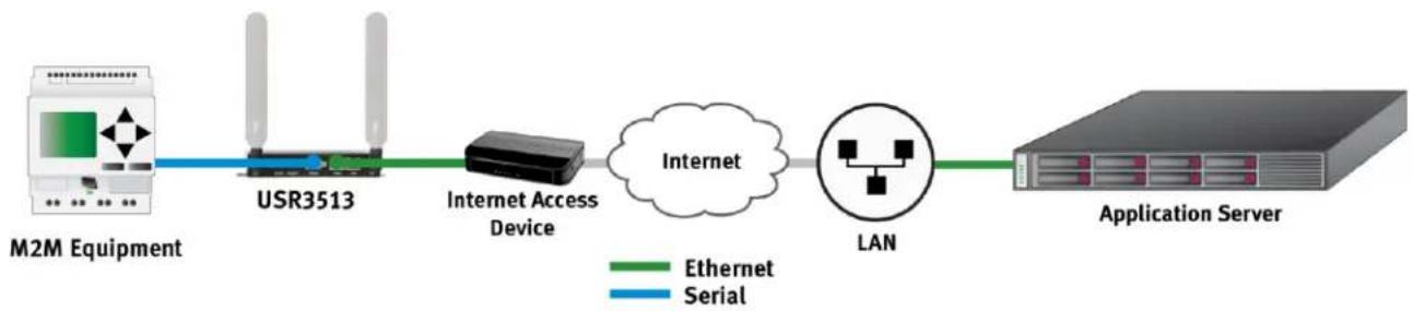
In cases where a remote site has wired access to the Internet as shown in figure 3, the Cellular Gateway's firewall can protect the remote equipment while allowing a connection to an application server via the Internet.

flowchart
graph LR
    A["M2M Equipment"] -->|Ethernet| B["USR3513"]
    B --> C["Internet Access Device"]
    C --> D["Internet"]
    D --> E["LAN"]
    E --> F["Application Server"]
figure 3
Also in cases where a remote site has wired access to the Internet, the Cellular Gateway can be used as a serial-to-Ethernet bridge, allowing remote serial equipment to contact an application server via the Internet to transmit M2M data, as shown in figure 4.
flowchart
graph LR
    A["M2M Equipment"] -->|Ethernet| B["USR3513"]
    B --> C["Internet Access Device"]
    C --> D["Internet"]
    D --> E["LAN"]
    E --> F["Application Server"]
    style A fill:#f9f,stroke:#333
    style F fill:#bbf,stroke:#333
    classDef blue stroke:#000,stroke-width:2px;
    classDef green stroke:#000,stroke-width:2px;
    classDef blue stroke:#000,stroke-width:2px;
    class A,B,C,D,E,F gray;
    class B,C,D,E,F gray;
    class E,F gray;
    class A,B,C,D,E,F gray;
    class B,C,D,E,F gray;
    class E,F gray;
figure 4
Those are just a few examples of how the versatile USR Courier M2M 4G LTE Cat 1 Cellular Gateway can be part of a traditional M2M or IoT data communications solution.
Package Contents
USR's Courier M2M 4G LTE Cat 1 Cellular Gateway is shipped with the following items. If any of these items are missing or damaged, please contact your customer service representative for assistance.
USR3513
• 1 USR3513 Cellular Gateway
• 1 Power supply with fixed blades for North America
• 2 4G/3G/2G omni-directional antennas, 0 dBi, SMA (male)
- 1 Ethernet cable
• 1 Quick start guide (printed)
USR803513
• 1 USR803513 Cellular Gateway
• 1 Power supply with interchangeable EU and UK blades
• 2 4G/3G/2G omni-directional antennas, 0 dBi, SMA (male)
- 1 Ethernet cable
• 1 Quick start guide (printed)
NOTE: The above items come with the standard Cellular Gateway models, but the package contents may vary for customized versions.
Product Highlights
Single unit supports multiple cellular networks
Configure for your cellular operator in less than a minute (USR3513)
Category 1 speeds on 4G LTE networks, ideal for M2M applications
➢ Fallback to 3G UMTS networks (USR3513) when outside of 4G LTE coverage
➢ Fallback to 2G networks (USR803513) when outside of 4G LTE coverage
➢ Interface to Ethernet or serial equipment
Includes two types of VPN for contacting an M2M server that's behind a firewall
User-friendly web interface for enabling connectivity, configuring the firewall, setting serial port parameters, and monitoring operational status
- Concealed SIM slot discourages unauthorized removal of SIM
- Can be remotely configured from a web browser
Product Specifications
Cellular Interface Standards
USR3513: LTE Cat 1, HSPA
USR803513: LTE Cat 1, GPRS
Band Options
USR3513
- LTE Cat 1: 1900/AWS1700/850/700 MHz (B2/B4/B5/B12/B13)
• HSPA/UMTS: 1900/850 MHz (B2/B5)
USR803513
- LTE Cat 1: 2100/1800/2600/900/800 MHz (B1/B3/B7/B8/B20)
• GPRS/GSM: 1800/900 MHz (B3/B8)
LTE Cat 1 Data Rate
- Downlink: Up to 10 Mbps
- Uplink: Up to 5 Mbps
HSPA Data Rate
- Downlink: Up to 42 Mbps (category 24)
• Uplink: Up to 5.7 Mbps (category 6)
GPRS Data Rate
- Downlink: Up to 58 Mbps (class 8)
• Uplink: Up to 14 Mbps (class 8) - Downlink: Up to 43 Mbps (class 10)
• Uplink: Up to 29 Mbps (class 10)
Cellular Antenna Connectors
1 Main, SMA female, 50 ohm
1 Auxiliary, SMA female, 50 ohm
Serial Interface
1 DB9-F connector, DCE, RS-232 or RS-485 signaling
Speeds (bps): 115200, 57600, 38400, 19200, 9600, 4800, 2400, 1200
Data Bits: 6, 7, 8
Parity: None, Odd, Even
Flow Control: None, Hardware
| Pin | RS-232 | RS-485 | ||
| 1 | * | - | - | - |
| 2 | TXD | O | TXD+ | O |
| 3 | RXD | I | RXD+ | I |
| 4 | DCD* | O | - | - |
| 5 | GND | - | GND | - |
| 6 | DTR* | I | - | - |
| 7 | CTS | I | RXD- | I |
| 8 | RTS | O | TXD- | O |
| 9 | - | - | - | - |


ATTENTION: *This is a non-standard pinout for an RS232 DCE on a DB9-F connector!
Applications that expect DCD and/or DSR signals from the DCE to drive DCD and DSR inputs will require a custom-wired cable or adaptor.
LAN Interface
1 RJ45 connector, Ethernet, 10/100 Mbps, auto MDI/MDIX
WAN Interface
1 RJ45 connector, Ethernet, 10/100 Mbps, auto MDI/MDIX
Power Connector
1 Barrel connector, 5.5 mm O.D., 2.1 mm I.D., center positive
LED Indicators
6 LEDs: POWER, RSSI, WAN, WAN 10/100, LAN, LAN 10/100
Reset Button
Reboot or Factory default + reboot, recessed
SIM Interface
1 SIM slot, 2FF, 1.8V/3V, USIM/SIM class B and class C
Power Requirements
Input Voltage: 8 to 12.5 VDC
Power Consumption: 3.6W idle (typical), 5.7W full load (typical)
Networking Protocols
• ICMP, TCP, UDP and ARP
- HTTP, HTTPS
- DHCP, Telnet, SSH
- IPSEC, OpenVPN
Security
IPsec
• Encryption: DES, 3DES, AES192, AES 256
• Authentication: MD5, SHA1
• Key Group: MODP1024, MODP1536
- Connection Type: Site-to-Site
OpenVPN
- Interface: TAP, TUN
- Protocol: TCP, UDP
- Connection Type: Site-to-Site
Firewall
- Remote Access
• DMZ
• Inbound Port Forwarding - Outbound Port Filtering
- Outbound Trusted IPs
Web Interface
Accessible via web browsers that support HTML5
Physical Characteristics
Housing: Industrial-grade steel
Dimensions: 5.85 x 4.46 x 1.04 in. (14.88 x 11.33 x 2.65 cm)
Weight: 0.95 lb (0.43 kg)
Installation: wall-mount or DIN-rail (DIN adaptor not included)
Environmental
Operating Temperature: -10 to 70°C
Storage Temperature: -40 to 85°C
Ambient Relative Humidity: 5 to 95% (non-condensing)
Regulatory Standards and Certifications
USR3513
• EMC: FCC, Industry Canada (IC)
• Network: PTCRB (module only)
- Carrier approvals: AT&T (module only)
Verizon (module only)
• Energy efficiency: DoE level VI
USR803513
• Safety & EMC: (see CE Declaration of Conformity)
• Network: GCF (module only)
• Energy efficiency: ErP level VI
• Hazardous Substances: RoHS compliant
Reliability
USR3513 MTBF: 1,110 yrs (module only)
USR803513 MTBF: 1,055 yrs (module only)
Warranty
Warranty Period: Two-year limited manufacturer warranty from date of purchase
Details: See www.usr.com/support/3513

ATTENTION: The USR3513 and the USR803513 are not portable cellular devices and should be located at least 20 cm away from the human body.

ATTENTION: The USR3513 and USR803513 Cellular Gateways use networking protocols. To setup and use these devices, familiarity with networking techniques is required.
Hardware Features

- LEDs
- SIM slot cover
- SIM slot cover screw

- Auxiliary antenna connector
- Recessed reset button
- Power input
- Serial port
- WAN port
- LAN port
- Main antenna connector
Bottom View

- Mounting flanges
- DIN adaptor mounting holes
LED Indicators

| LED | Display | Description | |
| POWER | ON | Indicates that the main power is on | |
| OFF | Indicates that the main power is off | ||
| RSSI | FlashingOn (mS) Off (mS) | Indicates that the cellular radio is active | |
| 600 | 1800 | Poor signal strength | |
| 800 | 1200 | Weak signal strength | |
| 1200 | 800 | Normal signal strength | |
| 1600 | 400 | Good signal strength | |
| 1800 | 200 | Excellent signal strength | |
| 200 | 1800 | No SIM | |
| 200 | 1800 | Not registered to a cellular network | |
| OFF | Indicates a cellular radio fault | ||
| WAN | ON | Indicates a connection to an active network | |
| Blinking | Indicates data traffic on the network | ||
| OFF | Indicates no connection to an active network | ||
| WAN 10/100 | ON | Indicates a 100BASE-T network | |
| OFF | Indicates a 10BASE-T network | ||
| LAN | ON | Indicates a connection to an active network | |
| Blinking | Indicates data traffic on the network | ||
| OFF | Indicates no connection to an active network | ||
| LAN 10/100 | ON | Indicates a 100BASE-T network | |
| OFF | Indicates a 10BASE-T network | ||
Reset Button
The recessed hardware reset button is located on the unit's back panel.

Using a pen or small screwdriver, press and hold as follows:
- If the reset button is pressed for less than one second it will be ignored.
- Hold for one to four seconds to perform a reboot when the button is released.
- If the reset button is pressed for more than four seconds up to ten seconds it will be ignored.
- Hold for more than ten seconds up to twenty seconds to restore factory settings and reboot when the button is released.
- If the reset button is pressed for more than twenty seconds it will be ignored.

Mounting
The Cellular Gateway provides two flanges for mounting to a wall or any other flat surface.
NOTE: Dimensions are in millimeters.
TOP VIEW

Mounting Flange Detail

| a | 42 |
| b | 8.5 |
| c | 12 |
| d | 4.0 |
| e | 25 |
| _1 | 3.2 |
| _2 | 5.0 |
| _3 | 3.0 |
DIN Rail Mounting
The Cellular Gateway provides mounting holes for a DIN rail adaptor.
BOTTOM VIEW

| a | 52.5 |
| b | 8.0 |
| c | 9.0 |
| d | 18 |
| e | 64.4 |
| _1 | M3-0.5 |
DIN rail adaptors with various mounting hole patterns are commercially available online and from electronics distributors.
Examples:

natural_image
Three metallic metal bracket components with mounting holes and internal notches (no text or symbols visible)Choose an adaptor with slots or holes whose diameter and positions line-up with one, two, or three of the Cellular Gateway's mounting holes.

ATTENTION: When fastening a DIN rail adaptor to the Cellular Gateway, use screws that will not extend more than 3 mm into the housing when fully tightened! Screws that extend further than 3 mm may damage the Cellular Gateway!
GETTING STARTED
Follow the steps in this chapter to setup a connection from the Cellular Gateway to a cellular data network.
Establishing a Cellular Connection
- Attach the included antennas to the antenna connectors on the back of the device.
- Make sure that a service plan is associated with a SIM card.
USR3513/USR803513 User Guide
3. To install the SIM:
- Remove the Phillips screw from the cover plate on the front of the unit and remove the plate.
- Insert the SIM into the SIM slot, oriented as shown in the picture below. The SIM must click into place.
- Replace the cover plate and the Phillips screw.

- Connect an Ethernet cable from the gateway's LAN port to the computer's Ethernet port.
- Power-up the Cellular Gateway by plugging the provided power supply into the power connector on the back of the Cellular Gateway, and into a power source. Allow one or two minutes for the Cellular Gateway to fully power up.
- Open a web browser on the computer and enter the address 192.168.10.250 into the address bar.
NOTE: Some browsers may display a security warning. Accept the warning to open an unencrypted https session.

- Enter the default User Name (admin) and Password (password).

After a successful login, the Status page will appear.
![10.250 x bps://192.168.10.250 Status Network Advanced Setup Admin Version: 01.26[1529509955] Your IP address: 192.168.10.105 Date: Tuesday, June 26, 2018 10:06:45 PM Uptime: 0 days, 0 hours, 23 minutes. IMEI: IMSI: ICC: Module revision: 20.00.522 Registration: Denied, Signal 20 (-73dBm) Area information: Country code: 0, Network code: 0, LAC: 0, Cell ID: 0 WAN IP: Netmask: Default Gateway: Received 0 (0.0 B), Transmitted 0 (0.0 B) LAN IP: 192.168.10.250 Netmask: 255.255.255.0 Received 17934 (17.5 KB), Transmitted 19135 (18.6 KB)](/content/2026/06/1213652/images/344ab022341cbbe55cd19fbf9ae095bc0c71b8b1db5ceba762a6767157b80ca7.jpg)
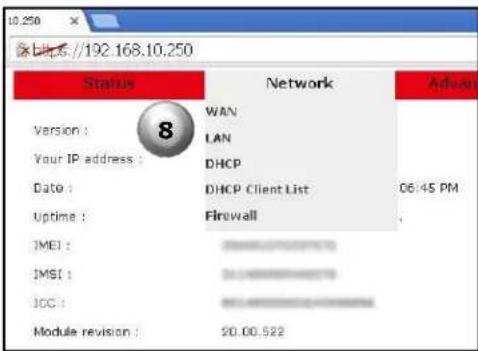
- Click Network on the red menu bar and select WAN.
USR3513/USR803513 User Guide
- For the USR3513: On the WAN page, with Mode set to WWAN, select the radio firmware for the cellular operator that you are using.
For the USR803513: Skip to the next step.
- Enter the APN (assigned by the cellular service provider) into the Access Point field.
- Enter a User name and Password if supplied by the cellular service provider.
- Click the Save button. A confirmation page will appear.

- Click the OK button. The WAN page will reappear.

- Click Status on the menu bar of the WAN page to confirm the cellular connection on the Status page.

A connection to the network will be setup automatically. When the connection is complete, entries will appear in the Registration, Area Information, WAN IP, WAN Netmask, and WAN Default Gateway fields.
The Cellular Gateway's date and time will automatically synchronize to the network clock.
![250km X x bps //192.168.10.250/config/index.shtml Status Network Advanced Setup Admin Version: 01.26[1529509955] Your IP address: 192.168.10.105 Date: Tuesday, June 26, 2018 8:52:37 AM Uptime: 0 days, 0 hours, 35 minutes. IMEI: IMSI: ICC: Modulo revision: 20.00.012 Registration: Home (Verizon), Signal 29 (~55dBm) Area information: Country code: 311, Network code: 480, LAC: 200B, Cell ID:2059670 WAN IP: 192.168.10.250 Netmask: 255.255.255.0 Default Gateway: 192.168.10.250 Received 124 (124.0 B), Transmitted 4955 (4.7 KB) LAN IP: 192.168.10.250 Netmask: 255.255.255.0 Received 89753 (86.6 KB), Transmitted 2462524 (2.3 MB)](/content/2026/06/1213652/images/a94245cda998f7fb672813b2a786c4d490c0164c814825a2b4121e40d4277a06.jpg)
Now you can proceed with configuring the Cellular Gateway for the target application.
CONFIGURATION
The following topics are covered in this chapter:
- Overview
- Accessing the Web Interface
Local Access
Remote Access
Logging In
• Navigating the Web Interface
- Status Page
- Network Menu
WAN Page
LAN Page
DHCP page
DHCP Client List
Firewall Page
• Advanced Setup Menu
Serial Page
IPSec Page
OpenVPN Page
- Administrator Menu
Logs Page
Time Page
F/W Upgrade Page
Password Page
Factory Reset Page
Save/Restore Settings page
Log out
Reboot Page
Overview
The USR Courier M2M 4G LTE Cat 1 Cellular Gateway provides an embedded web interface for a convenient and intuitive way to configure the Cellular Gateway and monitor its status.
In this chapter, default settings are identified by a Bold Italic font.
Accessing the Web Interface
The web interface is accessed locally via a web browser running on a computer connected to the gateway, or remotely via a web browser running on a computer or mobile device. The recommended web browsers are:
- IE 10 or newer
- Firefox (all)
- Opera 12 or newer
- Safari 6 or newer
- Chrome (all)
Local Access
Local access to the web interface is made by connecting an Ethernet cable from a computer to the LAN port of the Cellular Gateway.
To access the web interface, open a web browser on the computer and enter the IP address of the embedded web interface into the browser's address bar. The default IP address is 192.168.10.250, which can be changed later if desired.
NOTE: Some browsers may display a security warning. Accept the warning to open an unencrypted https session.

Remote Access
Remote access to the web interface can be made from a computer or mobile device* that has a connection to the Internet (or to a private network), under the following conditions:
√ The Cellular Gateway has Remote Access enabled
√ The Cellular Gateway has a cellular or a wired connection to the Internet (or to a private network)
√ The Cellular Gateway is at an IP address that is known and is routable from the computer or mobile device
*The Cellular Gateway's web interface is not optimized for viewing on mobile devices.
To access the web interface:
- Open a web browser on the computer or mobile device.
- Enter the https:// prefix, the IP address of the SIM, a colon (:), and the Remote Access port number into the address bar.
Example: https://10.24.85.5:1800 - Press/touch Enter
NOTE: Some browsers may display a security warning. Accept the warning to open an unencrypted https session.
Logging In
For either local access or remote access, a Login box will appear in the browser. Enter the default User Name (admin) and Password (password) and click the Log In button. The User Name and Password are case-sensitive.

NOTE: To prevent unauthorized access to the web interface, change the User Name and Password.
As a security measure, the web interface will automatically log out if it detects no activity for ten minutes. If the timeout expires, log back in to continue using the web interface.
Navigating the Web Interface
A Menu Bar is displayed at the top of the web interface. It allows navigation to each page of the web interface.
![10.250 https://192.168.10.250 Status Network Advanced Setup Administrator Version: 01.32[152554894] Your IP address: 192.168.10.105 Date: Wednesday, August 29, 2018 10:19:03 AM Uptime: 0 days, 0 hours, 6 minutes. IMEI: 3588610723363967 IMSI: 3584105844666733 ICC: 8881410723363967333 Module revision: 20.00.522 Registration: Home (AT&T), Signal 26 (-6idBm) Area information: Country code: 310, Network code: 410, LAC: 21972, Cell ID: 67647183 Menu Bar](/content/2026/06/1213652/images/a051f6d330ddcaaf102a7397b3f9d0c3cdb9b37d2333feae4dae101dd49062ec.jpg)
Click on an item in the Menu Bar to navigate to a page or to see a drop-down menu of more pages.
The items that are available in the Menu Bar are:
Status Page
Network Menu
- WAN Page
• LAN Page - DHCP Page
- DHCP Client List
- Firewall Page
Advanced Setup Menu
- Serial Page
- IPSec Page
- OpenVPN Page
Administrator Menu
- Logs Page
- Time Page
• F/W Upgrade Page - Password Page
- Factory Reset Page
- Save/Restore Settings Page
- Log out
- Reboot Page
Status Page
Choose Status in the menu bar to display the Status Page.
The Status Page is the web interface's home page. It displays important information about the operational status of the Cellular Gateway.
Each item is described in the following section.
![https://192.168.10.250/config/index.shtml Status Network Advanced Setup Administrator Version : 01.32[1535544894] Your IP address : 192.168.10.105 Date : Wednesday, August 29, 2018 2:15:18 PM Uptime : 0 days, 3 hours, 4 minutes. IMEI : IMSI : ICC : Module revision : 20.00.522 Registration : Home (AT&T), Signal 25 (-63dBm) Area information : Country code: 310, Network code: 410, LAC: 21972, Cell ID: 67647183 WAN IP : 10.16.44.2 Netmask : 255.0.0.0 Default Gateway : 10.16.44.3 Received 0 (0.0 B) , Transmitted 4492 (4.3 KB) LAN IP : 192.168.10.250 Netmask : 255.255.255.0 Received 51324 (50.1 KB) , Transmitted 1421803 (1.3 MB)](/content/2026/06/1213652/images/1851c453a4084afa02590fb35ba1071e1cf48caf81677a823090b0ac971de3a5.jpg)
Version
Version :
01.32[1535544894]
Displays the version number of the Cellular Gateway's firmware, and a firmware build identifier.
Your IP Address
Your IP address : 192.168.10.105
During a local access session, this displays the IP address of the computer connected to the Cellular Gateway.
During a remote access session, this displays the IP address of the computer or mobile device connected remotely to the Cellular Gateway.
Date
Date : Wednesday, August 29, 2018 2:15:18 PM
When the Cellular Gateway has a cellular connection or has a wired connection to a network that has an NTP server, the Cellular Gateway's date and time will automatically synchronize to the network.
When no NTP server is found, a default date and time will display.
Uptime
Uptime : 0 days, 3 hours, 4 minutes.
Displays the time duration since the last power-up or reboot.
IMEI
IMEI :
Displays the International Mobile Equipment Identity number, which is a unique identifier of the Cellular Gateway's embedded radio module.
IMSI
IMSI :

Displays the International Mobile Subscriber Identity number, which is a unique identifier of the cellular subscriber associated with the SIM installed in the Cellular Gateway's SIM slot.
ICC
ICC :

Displays the Integrated Circuit Card Identifier (ICCID) number, which is a unique identifier printed on the SIM installed in the Cellular Gateway's SIM slot.
Module Revision
Module revision :
20.00.522
Displays the embedded radio module's firmware version number.
Registration
Displays the status of the Cellular Gateway's connection to a cell tower.
Registration status
Registration :
Home (Verizon), Signal 29 (-55dBm)
Home (Operator): Displayed when the Cellular Gateway is connected to a cell tower that is operated by a carrier with which the SIM has an active subscription. Operator displays the name of the cell tower operator.
Roaming (Operator): Displayed when the Cellular Gateway has a roaming connected to a cell tower that is not operated by a carrier with which the SIM has an active subscription. Operator displays the name of the cell tower operator.
Not registered, ME is not currently searching a new operator to register: Displayed when the Cellular Gateway is not currently searching for a connection to a cell tower.
Not registered, but ME is currently searching a new operator to register: Displayed when the Cellular Gateway is actively searching for a connection to a cell tower.
➢ Denied: Displayed when a cell tower has refused a connection request from the Cellular Gateway.
Unknown: Displayed when none of the above conditions apply.
Signal quality and strength
When the Cellular Gateway is registered with a cell tower, the signal quality and signal strength are displayed as two numbers.
Registration :
Home (Verizon), Signal 29 (-55dBm)
The first number that follows the (Operator) is a signal quality measurement that ranges from 31 (best) to 0 (worst). When no connection is found, the number 99 is displayed.
The number in parenthesis is the signal strength displayed in dBm, which ranges from -51 dBm (strongest) to -113 dBm (weakest). When the Cellular Gateway is not registered or couldn't find a cell tower, -125 dBm is reported.
Good: -51 to -79 dBm
Fair: -80 to -103 dBm
Bad: -104 to -113 dBm, -125 dBm
Area Information
Area information :
Country code: 310, Network code: 410, LAC: 21972, Cell ID: 67647183
Displays information about the cell tower to which the Cellular Gateway has registered.
Country code: The country code number reported by the cell tower.
Network code: The cellular operator code number reported by the cell tower.
LAC: The location area code number reported by the cell tower.
Cell ID: The cell ID number reported by the cell tower.
WAN
WAN
IP : 10.16.44.2
Netmask : 255.0.0.0
Default Gateway : 10.16.44.3
Received 0 (0.0 B), Transmitted 4492 (4.3 KiB)
This section displays information about the WWAN (cellular) or WAN (Ethernet) connection.
The network information displayed in this section depends on the Mode setting in the WAN page and the DCHP setting in the WAN page. The following table shows how the network information is effected by the Mode and DHCP settings.
| Mode Setting | DHCP Setting | IP | Netmask | Default Gateway |
| WWAN | n/a | Assigned by the cellular network | Assigned by the cellular network | Assigned by the cellular network |
| WAN | Enable | Assigned by the local-area network | Assigned by the local-area network | Assigned by the local-area network |
| Disable | Assigned manually in the WAN page | Assigned manually in the WAN page | Assigned manually in the WAN page |
Received & Transmitted
Displays the cumulative number of bytes received and transmitted over either type of WAN connection since the last power-up or reboot.
VPN
The Cellular Gateway provides two types of VPN on its WAN connection: IPSec and OpenVPN.
When the Cellular Gateway has IPSec enabled, this section appears and displays information about the VPN connection.
VPN
IPsec : Connected
Remote Client IP : 172.18.3.8
IPSec Status
Displays Idle when IPSec is enabled but a tunnel is not established.
Displays Connected when an IPSec tunnel is established.
Remote IP
Reports the IP address of the IPSec endpoint at the far end of the VPN tunnel.
Remote Client IP is reported when the other VPN endpoint is an IPSec client.
Remote Gateway IP is reported when the other VPN endpoint is an IPSec gateway.
When the Cellular Gateway has OpenVPN enabled, this section appears and displays information about the VPN connection.
VPN
OpenVPN : Connected
IP : 10.9.1.6
OpenVPN Status
Displays Idle when an OpenVPN client is enabled but a tunnel is not established.
Displays Listening when an OpenVPN server is enabled but a tunnel is not established.
Displays Connected when an OpenVPN tunnel is established.
IP
Reports the IP address of the OpenVPN endpoint at the far end of the VPN tunnel.
LAN
| LAN | |
| IP : | 192.168.10.250 |
| Netmask : | 255.255.255.0 |
| Received 51324 (50.1 KiB) , Transmitted 1421803 (1.3 MiB) | |
This section displays information about the Cellular Gateway's LAN port.
IP
Displays the current IP address of the Cellular Gateway's LAN port. The embedded web interface is accessed at this IP address. The default IP address is 192.168.10.250, which can be changed on the LAN page.
Netmask
Displays the current IP netmask of the Cellular Gateway's LAN port. The default netmask is 255.255.255.0, which can be changed on the LAN page.
Received & Transmitted
Displays the cumulative number of bytes received and transmitted over the LAN connection since the last power-up or reboot.
Network Menu
Choose Network in the menu bar to display the Network Menu.

Select WAN from the Network Menu to display the WAN Page.
Select LAN from the Network Menu to display the LAN Page.
Select DHCP from the Network Menu to display the DHCP Page.
Select DHCP Client List from the Network Menu to display the DHCP Client List.
Select Firewall from the Network Menu to display the Firewall Page.
Each is described in the following section.

ATTENTION: The USR3513 and USR803513 Cellular Gateways use networking protocols. To setup and use these devices, familiarity with networking techniques is required.
WAN Page
This page configures the Cellular Gateway to connect either to a local-area network via the gateway's WAN port, or to a cellular data network.
Changes to settings on this page don't take effect until saved!


NOTE: For access to a cellular data network, contact a cellular network operator for a subscription to a cellular data plan.
Mode
This setting chooses a WWAN (cellular) or WAN (Ethernet) connection.
Mode :
WWAN
WWAN: The Cellular Gateway's embedded radio module will try to connect to a cellular data network.
WAN: The Cellular Gateway's WAN port will try to connect to a local-area network.
Operator (USR3513 only)
This setting configures the embedded radio module firmware for a specific cellular network.
Operator :
AT&T & T-Mobile ▼
Verizon: The embedded radio module will run firmware that is approved for the Verizon 4G LTE cellular network.
AT&T & T-Mobile: The embedded radio module will run firmware that is approved for the AT&T 4G LTE cellular network and also works on the T-Mobile 4G LTE cellular network.
LTE Generic: The embedded radio module will run firmware that works on most other 4G LTE cellular networks.
Access Point
The cellular network operator usually will provide an APN (Access Point Name) to the subscriber. Enter the APN into this field to connect to the Internet via the cellular data network.
Access Point :
internet

NOTE: If the cellular network also required a User name and/or Password, the connection will not complete until a valid User name and/or Password is entered.
USR3513/USR803513 User Guide
User name
User name :
The cellular network operator may provide an assigned User name, or may provide instructions for choosing a User name. Enter the User name into this field. Leave it blank if a User name is not required by the cellular network.
Password
Password :
The cellular network operator may provide an assigned Password, or may provide instructions for choosing a Password. Enter the Password into this field. Leave it blank if a Password is not required by the cellular network.
Authentication
Authentication :
No Auth
No Auth: Use this setting when the WAN connection is not authenticating Point-to-Point Protocol (PPP).
PAP: Password Authentication Protocol is used by Point-to-Point Protocol (PPP) to authenticate clients. Use this setting when connecting to a PPP server that requires PAP authentication.
CHAP: Challenge Handshake Authentication Protocol is a secure method to authenticate clients used by Point-to-Point Protocol (PPP). Use this setting when connecting to a PPP server that requires CHAP authentication.
USR3513/USR803513 User Guide
DHCP
The Cellular Gateway's DHCP client lets a network automatically assign an IP address to the gateway's WWAN or WAN connection.
When Mode is set to WWAN, the DHCP client is enabled and no selection is available.
DHCP :
When Mode is set to WAN, the DHCP client is disabled by default and a DHCP pull-down menu becomes available.
DHCP :
Disable
Enable: Use this setting so the Cellular Gateway's WAN port can automatically get an IP address from a DHCP server on the local-area network.
Disable: Use this setting when the Cellular Gateway's WAN port must have a manually-assigned static IP address on the local-area network.

NOTE: Consult with the local-area network's administrator before attaching any device that has a static IP address to a network.
IP Address, Subnet mask, Gateway, DNS
| IP Address : | 0.0.0.0 |
| Subnet mask : | 255.255.255.0 |
| Gateway : | 0.0.0.0 |
| DNS : | 8.8.8.8 |
The contents of these fields depends on the Mode setting and the DCHP setting.
When Mode is set to WWAN, these fields are undefined. Addresses are assigned by the cellular network.
When Mode is set to WAN and DHCP is set to Enable, these fields are undefined. Addresses are assigned by the local-area network.
When Mode is set to WAN and DHCP is set to Disable, enter a network IP Address, Subnet mask, Gateway address, and DNS address into these fields.
Save button
Save
Changes made on this page do not take effect until saved. Click the Save button to make changes effective. To discard all changes made on the page, navigate to another page or log out of the web interface.
LAN Page
This page configures the IP address and subnet mask of Cellular Gateway's LAN port.
Changes to settings on this page don't take effect until saved!

IP Address
IP Address :
192.168.10.250
The Cellular Gateway's LAN IP address is static, and the default is 192.168.10.250.
To change the IP address of the Cellular Gateway's LAN port, enter the new IP address into this field and click the Save button.
When choosing a new LAN address, basic network principles must be followed. For example when three nodes have static IP addresses and the Cellular Gateway's DHCP server is enabled:

flowchart
graph TD
    A["Host IDs must not match, and must stay outside DHCP range"] --> B["Prefixes must match"]
    B --> C["IP addresses"]
    C --> D["192.168.10.250"]
    B --> E["192.168.10.87"]
    B --> F["192.168.10.235"]
    B --> G["192.168.10.222"]
    H["USR3513"] --> I["DHCP range 100 - 119"]
    I --> J["LAN port"]
    J --> K["Computer"]
    J --> L["Computer"]
    J --> M["Computer"]
Subnet mask
Subnet mask :
255.255.255.0
The default LAN subnet mask is 255.255.255.0.
To change the subnet mask of the Cellular Gateway's LAN port, enter the new subnet mask into this field and click the Save button.
USR3513/USR803513 User Guide
Save button

Changes made on this page do not take effect until saved. Click the Save button to make changes effective. To discard all changes made on the page, navigate to another page or log out of the web interface.
DHCP page
This page enables/disables and configures the Cellular Gateway's DHCP server.
Changes to settings on this page don't take effect until saved!

Activate
Activate :
Enable
Enable: This setting enables the Cellular Gateway's DHCP server. Use this setting when any node attached to the Cellular Gateway's LAN port will request a DHCP IP address.
For example, when using a computer to access the Cellular Gateway's web interface, the computer normally will request an IP address and the Cellular Gateway's DHCP server will assign an IP address to the computer.
Disable: This setting disables the Cellular Gateway's DHCP server. Use this setting when all nodes attached to the Cellular Gateway's LAN port have a manually-assigned static IP address.
NOTE: When all nodes have a static IP address, the DHCP server can remain enabled, provided that all of the static IP addresses are outside the DHCP range. That way, a computer can easily join the network to access the Cellular Gateway's web interface.
When choosing static IP addresses, basic network principles must be followed. For example when three nodes have static IP addresses and the Cellular Gateway's DHCP server is enabled:

flowchart
graph TD
    A["Host IDs must not match, and must stay outside DHCP range"] --> B["Prefixes must match"]
    B --> C["IP addresses 192.168.10.250"]
    B --> D["192.168.10.87"]
    B --> E["192.168.10.235"]
    B --> F["192.168.10.222"]
    G["USR3513"] --> H["DHCP range 100 - 119"]
    H --> I["LAN port"]
    I --> J["Server"]
    I --> K["Server"]
    I --> L["Server"]
Offset
Offset :
100
This entry sets the lowest Host ID number that the Cellular Gateway's DHCP server can assign. The allowed range is 1 - 254. The default value is 100.
USR3513/USR803513 User Guide
Range
| Range : | 20 |
This entry sets the number of sequential Host ID numbers that the Cellular Gateway's DHCP server can assign. The allowed range is 1 - 254. The default value is 20.
The highest Host ID number that the DHCP server can assign is (Offset + Range - 1).
DNS
When any node connected to the Cellular Gateway's LAN port tries to connect to a URL (instead of an IP address), the Cellular Gateway will try to resolve the URL into an IP address by consulting a DNS server.
| DNS : | 192.168.10.250 |
| DNS : | 8.8.8.8 |
The first DNS entry contains the IP address of the primary DNS server.
In an M2M system, using a URL to contact a host may be handy when the host has a dynamic IP address and reports its current IP address to a DNS server. So if the application will be using URLs, enter the IP address of the host's primary DNS server into this field.
DNS
| DNS : | 192.168.10.250 |
| DNS : | 8.8.8.8 |
This entry contains the IP address of an alternate DNS server.
If the application will be using URLs, enter the IP address of the host's alternate DNS server into this field.
Lease Time
When the Cellular Gateway's DHCP server assigns an IP address to a DHCP client attached to the LAN port, the DHCP protocol also assigns a lease time to that client. When the lease expires, the DHCP client is required to send another DHCP request.
Lease Time :
3600
The default value is 3600 seconds. The allowed range is 60 to 3880000 seconds.
Save button
Save
Changes made on this page do not take effect until saved. Click the Save button to make changes effective. To discard all changes made on the page, navigate to another page or log out of the web interface.
DHCP Client List
When the Cellular Gateway's DHCP server has assigned IP addresses to DHCP clients, this page displays information about the DHCP clients and the DHCP leases.
Each row on this page displays information about one DHCP client.

Firewall Page
This page configures the Cellular Gateway's firewall.
Changes to settings on this page don't take effect until saved!

Default policies
Default policies
LAN -> WAN
WAN -> Local
Reject

Drop

The default policies control two data paths thru the gateway:
• LAN -> WAN controls outbound connections and data sent to the WAN (cellular or Ethernet).
- WAN -> Local controls inbound connections and data received from the WAN (cellular or Ethernet).
LAN -> WAN
Accept: Connections from the Cellular Gateway's LAN port to the WAN are allowed. Connections from the Cellular Gateway's IPSec and OpenVPN endpoints to the WAN are allowed. Data sent from the serial port's UDP server to the WAN is allowed.

CAUTION: When LAN -> WAN is set to Accept and the WAN is cellular, a computer attached to the LAN port during gateway set-up may use the cellular connection for all of its Internet access activities. Data usage can be very high, and the usage is billable by the cellular operator.
To prevent this excessive data usage, consider using Port Filtering or Trusted IPs.
Reject: Connections from the Cellular Gateway's LAN port to the WAN are blocked. Connections from the Cellular Gateway's IPSec and OpenVPN endpoints to the WAN are blocked. Data sent from the serial port's UDP server to the WAN is blocked.
Drop: This setting is similar to Reject, except the Cellular Gateway does not notify LAN nodes that the connection is blocked.
WAN -> Local
Accept: Connections from the WAN to the Cellular Gateway's LAN port are allowed. Connections from the WAN to the Cellular Gateway's IPSec and OpenVPN endpoints are allowed. Connections and data from the WAN to the serial port's TCP/UDP servers are allowed.

CAUTION: When WAN -> Local is set to Accept, the Cellular Gateway and the LAN nodes are vulnerable to attacks from the Internet. For a more secure system, get a private IP address from the cellular operator.
Reject: Connections from the WAN to the Cellular Gateway's LAN port are blocked. Connections from the WAN to the Cellular Gateway's IPSec and OpenVPN endpoints are blocked. Connections and data from the WAN to the serial port's TCP/UDP servers are blocked.

CAUTION: When WAN -> Local is set to Reject, the Cellular Gateway will not allow an inbound connection, but it will notify the source of the request that the connection is blocked. That response may alert attackers and prompt further attacks.
Drop: This setting is similar to Reject, except the Cellular Gateway does not notify the source of the request that connections are blocked. Use this setting to minimize the chance of being attacked from the Internet.
Remote Access
Remote access allows a remote computer or mobile device* to log into the Cellular Gateway's embedded web interface, under the following conditions:
√ The Cellular Gateway has Remote Access enabled
√ The Cellular Gateway has a cellular or a wired connection to the Internet (or to a private network)
√ The Cellular Gateway is at an IP address that is known and is routable from the computer or mobile device
*The Cellular Gateway's web interface is not optimized for viewing on mobile devices.
Disable: Use this setting to reject a remote access session.
Remote Access
Disable

In order for the changes to take effect, please reboot your gateway after saving
Enable: Use this setting to accept a remote access session. A field will appear for entering a port number. The port field sets the port number that the Cellular Gateway is listening to for a Remote Access connection.
The default value is 1800. The allowed range is 0 to 65535.
Remote Access
Enable

1800
In order for the changes to take effect, please reboot your gateway after saving
Remote Access does NOT require setting the WAN -> Local default policy to Accept.
NOTE: In order for the enable or disable setting to take effect, reboot the gateway after saving!

CAUTION: When Remote Access is Enabled, the Cellular Gateway is vulnerable to attacks from the Internet. For a more secure system, get a private IP address from the cellular operator.
To open a Remote Access session:
- Open a web browser on the computer or mobile device.
- Enter the https:// prefix, the IP address of the SIM, a colon (:), and the Remote Access port number into the address bar.
Example: https://10.24.85.5:1800
-
Press/touch Enter.
-
Log in.
NOTE: Some browsers may display a security warning. Accept the warning to open an unencrypted https session.
DMZ
DMZ is one way to pass inbound data through the Cellular Gateway to a node on its LAN. (The other way is Inbound Port Forwarding.)

flowchart
graph LR
    A["Terminal"] -->|LAN| B["Secure VPN Connection"]
    B --> C["Firewall"]
    C --> D["USR3513"]
    D --> E["M2M Equipment"]
    style A fill:#f9f,stroke:#333
    style B fill:#ccf,stroke:#333
    style C fill:#cfc,stroke:#333
    style D fill:#fcc,stroke:#333
    style E fill:#cff,stroke:#333
NOTE: To allow a host to connect to the Cellular Gateway, the Cellular Gateway's SIM must be provisioned with a static IP address. And for security reasons, that static IP address should be private (not a public address on the Internet). The cellular operator must therefore provide a VPN connection from the host into their private network to allow the host to reach the private static IP address of the Cellular Gateway, as illustrated above.
DMZ configures a demilitarized (safe) zone on the Cellular Gateway's LAN. This feature forwards all inbound data to a specific IP address on the Cellular Gateway's LAN to protect any other nodes on the LAN.
Disable: Disables the DMZ feature.

Enable: Enables the DMZ feature. A field will appear for entering the IP address that is used for forwarding all inbound data to the LAN.


NOTE: By default the Cellular Gateway's serial port is a server listening at port 6000. To avoid port conflicts when using DMZ:
Don't send any data to the gateway on port 6000, or
➢ Set the serial server to listen at an unused port, or
Change the serial Mode to Client
Inbound port forwarding
Inbound Port Forwarding is one way to pass inbound data through the Cellular Gateway to a node on its LAN. (The other way is DMZ.)

flowchart
graph LR
    A["NOC"] -->|LAN| B["Secure VPN Connection"]
    B --> C["Firewall"]
    C --> D["USR3513"]
    D --> E["M2M Equipment"]
    style A fill:#f9f,stroke:#333
    style B fill:#ccf,stroke:#333
    style C fill:#cff,stroke:#333
    style D fill:#ffc,stroke:#333
    style E fill:#cfc,stroke:#333
NOTE: To allow a host to connect to the Cellular Gateway, the Cellular Gateway's SIM must be provisioned with a static IP address. And for security reasons, that static IP address should be private (not a public address on the Internet). The cellular operator must therefore provide a VPN connection from the host into their private network to allow the host to reach the private static IP address of the Cellular Gateway, as illustrated above.

The Inbound Port Forwarding section of the Firewall page lists the Inbound Port Forwarding rules, up to a maximum of 24.
Each rule, in sequence, evaluates the inbound data's protocol, source IP address, and destination port number. When more than one rule is set up, the first line has the highest priority.
If the inbound data's protocol, source IP address, and destination port number match the entries in a rule, the data will be forwarded to that rule's Local IP and Local Port entries on the Cellular Gateway's LAN.
If no match is found by the rules:
• the data may be passed thru the Cellular Gateway by DMZ (if enabled), or
• the data will be blocked
Protocol

Use this setting to choose a protocol qualifier for the rule.
TCP: The inbound data must be TCP for the rule to accept it.
UDP: The inbound data must be UDP for the rule to accept it.
Both: The rule will accept both TCP and UDP protocols.
Source IP

Use this setting to choose a source IP address qualifier for the rule.
Any: The rule will accept data from any source IP address.
Specific: The inbound data must be from this source IP address for the rule to accept it.
NOTE: When a rule requires a specific source IP address, the source must have a static IP address, and the address must not be changed by Network Address Translation (NAT).
Dest. Port

Enter a port number qualifier for the rule. The inbound data must have been sent to this destination port number for the rule to accept it.

NOTE: By default the Cellular Gateway's serial port is a server listening at port 6000. To avoid port conflicts when using Inbound Port Forwarding:
Don't send any data to the gateway on port 6000, or
➢ Set the serial server to listen at an unused port, or
Change the serial Mode to Client
Local IP, Local Port

These entries define where this rule will send data that is accepted. Enter the target node's IP address and port number.
NOTE: The target node must have a static IP address.
Add+ button
Add+
Click the Add+ button to create a port forwarding rule using the above entries. New rules are added below previous rules.
To remove a rule, click the Delete button next to the rule.
NOTE: Add rules in the order of their priority (highest first).
Outbound port filtering
When Default Policies LAN -> WAN setting is set to Reject or Drop, nodes on the Cellular Gateway's LAN cannot connect and send data to any IP address on the WAN. Outbound Port Filtering is one way to control where nodes on the LAN can send outbound data when LAN -> WAN is set to Reject or Drop. (The other way is Outbound Trusted IPs.)
Port range
Policy

Accept
Add+
The Outbound Port Filtering section of the Firewall page lists the Outbound Port Filtering rules, up to a maximum of 24.
Each rule, in sequence, evaluates the outbound data's destination port number. When more than one rule is set up, the first line has the highest priority.
Port range

Enter a port number into each text field to specify a range of port numbers for the rule. Both values must be in the range of 0 to 65535, and the second value must be greater than or equal to the first.
Policy

Use this setting to choose a policy that specifies what this rule will do based on the outbound data's destination port number.
Accept: If the outbound data's destination port number is within the range of the rule, the data is passed to the WAN. Outbound data whose destination port number is outside the range of the rule is blocked.
Reject: If the outbound data's destination port number is within the range of the rule, the data is blocked. Outbound data whose destination port number is outside the range of the rule is passed to the WAN.
Drop: This setting is similar to Reject, except the Cellular Gateway does not notify LAN nodes that the connection is blocked.
USR3513/USR803513 User Guide
Add+ button
Add+
Click the Add+ button to create a port filtering rule using the above entries. New rules are added below previous rules.
To remove a rule, click the Delete button next to the rule.
NOTE: Add rules in the order of their priority (highest first).
Outbound trusted IPs
When Default Policies LAN -> WAN is set to Reject or Drop, nodes on the Cellular Gateway's LAN cannot connect and send data to any IP address on the WAN. Outbound Trusted IPs is one way to control where nodes on the LAN can send outbound data when LAN -> WAN is set to Reject or Drop. (The other way is Outbound Port Filtering.)
The Outbound Trusted IPs section of the Firewall page lists the trusted IP addresses, up to a maximum of 24.
If the outbound data's destination IP address is found in any trusted IP rule, the data is passed to the WAN. Outbound data whose destination IP address is not found is blocked.

Enter the IP address of a trusted host into the Outbound trusted IPs text field.
NOTE: The host must have a static IP address.
Add+ button
Add+
Click the Add+ button to create a trusted IP rule using the above entry. New rules are added below previous rules.
To remove a rule, click the Delete button next to the rule.
USR3513/USR803513 User Guide
Save button
Save
Changes made on this page do not take effect until saved. Click the Save button to make changes effective. To discard all changes made on the page, navigate to another page, or log out of the web interface, or click the Cancel button.
Cancel button
Cancel
The Cancel button provides a way to discard all changes made on the Firewall page without navigating away or logging out.
Advanced Setup Menu
Choose Advanced Setup in the menu bar to display the Advanced Setup Menu.
![https://192.168.10.250 https://192.168.10.250 Status Network Advanced Setup Administrator Version: 01.32[1535544894] Serial Your IP address: 192.168.10.105 IPSec Openvpn Date: Wednesday, August 29, 2018 10:19:03 AM Uptime: 0 days, 0 hours, 6 minutes. IMEI: Imeia.ac/192.168.10.250](/content/2026/06/1213652/images/2fdfa11bf11820ed9261a1388eeb74d44ad252c994a8496ee279a1f9cb19f4d2.jpg)
Select Serial from the Advanced Setup Menu to display the Serial Page.
Select IPSec from the Advanced Setup Menu to display the IPSec Page.
Select OpenVPN from the Advanced Setup Menu to display the OpenVPN Page.
Each is described in the following section.

ATTENTION: The USR3513 and USR803513 Cellular Gateways use networking protocols. To setup and use these devices, familiarity with networking techniques is required.
Serial Page
This page configures the network settings and serial parameters of the Cellular Gateway's serial port.
Changes to settings on this page don't take effect until saved!

Line driver
Line driver :
RS232
The Cellular Gateway's serial port can use either RS232 or RS485 signaling. See Product Specifications for the serial port's pinout in each Line Driver mode.
RS485: Choose this setting to use four-wire full-duplex differential signaling.
RS232: Choose this setting to use RS232 signaling.
Baudrate
| Baudrate : | 115200 |
Select a baudrate that matches the baudrate used by the equipment attached to the serial port.
Data
| Data : | 8 |
Select a word length that matches the word length used by the equipment attached to the serial port.
Parity
| Parity : | None |
Select a parity that matches the parity used by the equipment attached to the serial port.
Stop
| Stop: | 1 |
Select the number of stop bits that matches the number used by the equipment attached to the serial port.
Flow
| Flow : | None |
None: Use this setting when the equipment attached to the serial port doesn't use flow control.
Hardware: Use this setting when the equipment attached to the serial port uses hardware flow control.
Mode
Mode :
Server
The Cellular Gateway can bridge data received from a host on the WAN to its serial port, and it can bridge data from its serial port to a host on the WAN.
Server: The Cellular Gateway listens at a port for a TCP connection or for UDP data from a remote client so it can bridge the data to its serial port.
Client: The Cellular Gateway tries to open a TCP connection or send UDP data to the IP address and port number of a remote server so it can bridge the data to its serial port.
IPStack
When serial Mode is set to Server, the IPStack display confirms that Server protocols are being used.
IPStack
Server
When serial Mode is set to Client, the IPStack display confirms that Client protocols are being used.
IPStack
Client
Protocol
Protocol :
TCP
The Cellular Gateway's serial bridge can use either TCP or UDP protocols for exchanging data with a host on the WAN.
UDP: Use this setting when the serial bridge needs to exchange data with a UDP host.
TCP: Use this setting when the serial bridge needs to connect and exchange data with a TCP host.
Serial Port Operation
When the serial Mode is set to Server, a Listen port entry field is displayed. Enter the port number that the remote TCP or UDP client will use to contact the Cellular Gateway's serial port.
When Protocol is set to TCP, the serial port is full-duplex. Subject to firewall rules, a bidirectional connection can be made from the remote client to the gateway's listen port.
When Protocol is set to UDP, the serial port can receive data from the remote client and then reply. Subject to firewall rules, data is received on the Listen port. Subject to firewall rules, replies are sent to the remote client's source address and port.
The default value is 6000. The allowed range is 0 to 65535.
| Listen port : | 6000 |
When the serial Mode is set to Client and Protocol is set to TCP, the serial port is full-duplex regardless of firewall rules. Destination IP and Destination port entry fields are displayed. Enter the IP address and listener port number of the remote TCP server.
The default port value is 6000. The allowed port range is 0 to 65535.
| Destination IP : | 0.0.0.0 |
| Destination port : | 6000 |
When the serial Mode is set to Client and Protocol is set to UDP, the serial port can send data to the remote server and then receive a reply, regardless of firewall rules. Destination IP, Destination port, and Source port entry fields are displayed. Enter the IP address and listener port number of the remote UDP server, and the listener port number of the local client. UDP data is received on the Source port, and sent to the Destination port.
NOTE: The remote server must have a static IP address.
Save button
Save
Changes made on this page do not take effect until saved. Click the Save button to make changes effective. To discard all changes made on the page, navigate to another page or log out of the web interface.
IPSec Page
The Cellular Gateway provides two types of VPN on its WAN connection: IPSec and OpenVPN. This page enables/disables and configures the Cellular Gateway's IPSec protocols.
- The IPSec client protocols can initiate a VPN on the WAN connection to an IPSec gateway.
- The IPSec gateway protocols can listen on the WAN for a VPN connection from an IPSec client.

ATTENTION: To setup a VPN, both endpoints of the tunnel must be configured!
The settings in the Cellular Gateway have corresponding settings in the other VPN host. Consult with the administrator of the other VPN host to configure those settings.
Changes to settings on this page don't take effect until saved!


ATTENTION: Once an IPSec connection is established, it will periodically consume a significant amount of data to maintain the connection. Be sure to subscribe to a cellular data plan that is large enough for IPSec data usage plus the application data usage.

flowchart
graph LR
    A["M2M equipment"] -->|LAN| B["USR3513"]
    B --> C["Internet"]
    C --> D["VPN Host"]
    D --> E["application server"]
    style A fill:#f9f,stroke:#333
    style B fill:#ccf,stroke:#333
    style C fill:#cfc,stroke:#333
    style D fill:#fcc,stroke:#333
    style E fill:#cff,stroke:#333
figure 5: VPN Network Overview
Gateway/Client
Gateway/Client :
Disable

Disable: Use this setting to disable IPSec protocols.
Client: Use this setting to enable IPSec client protocols to initiate a VPN on the WAN connection to an IPSec gateway.
NOTE: When the IPSec client is enabled, the firewall must be configured to allow outbound data.
Gateway: Use this setting to enable IPSec gateway protocols to listen on the WAN for a VPN connection from an IPSec client.
NOTE: When the IPSec gateway is enabled, the firewall must be configured to allow inbound data.
USR3513/USR803513 User Guide
Local Group FQDN (Fully Qualified Domain Name)
Local Group FQDN :

When Gateway/Client is set to Disable, this field is undefined.
When Gateway/Client is set to Client or Gateway, this is a required field. Choose and enter a fully qualified domain name of the Cellular Gateway 1.
This entry is case-sensitive.
Remote IP
Remote IP :

When Gateway/Client is set to Disable or Gateway, this field is undefined.
When Gateway/Client is set to Client, this is a required field. Enter the public WAN IP address of the IPSec endpoint at the far end of the VPN tunnel ② into this field.
Remote Group IP
Remote Group IP :

When Gateway/Client is set to Disable, this field is undefined.
When Gateway/Client is set to Client or Gateway, this is a required field. Enter the network address of the other IPSec host's LAN ③ into this field.
NOTE: The network address is the network prefix with a host ID=0.
Example: 192.168.20.0
NOTE: The Cellular Gateway's LAN network IP address must NOT match the LAN network IP address of the other IPSec host.
Remote Group Subnet
Remote Group Subnet :

When Gateway/Client is set to Disable, this field is undefined.
When Gateway/Client is set to Client or Gateway, this is a required field. Enter the subnet mask of the other IPSec host's LAN 4 into this field.
Remote FQDN (Fully Qualified Domain Name)
Remote FQDN :

When Gateway/Client is set to Disable, this field is undefined.
When Gateway/Client is set to Client or Gateway, this is a required field. Enter the fully qualified domain name of the IPSec host at the far end of the VPN tunnel ⑤ into this field.
This entry is case-sensitive.
Pre Shared Key
Pre Shared Key :

When Gateway/Client is set to Disable, this field is undefined.
When Gateway/Client is set to Client or Gateway, this is a required field. Enter a Pre-Shared Key that matches the Pre-Shared Key entry of the other IPSec host.
This entry is case-sensitive.
USR3513/USR803513 User Guide
Aggressive Mode
Aggressive Mode :
On
This setting must match the setting in the other IPSec host.
Off: Use this setting for IPSec main mode.
On: Use this setting for IPSec aggressive mode.
Perfect Forward Secrecy
Perfect Forward Secrecy :
Off
This setting must match the setting in the other IPSec host.
Off: Use this setting if the other IPSec host doesn't support PFS.
On: Use this setting for PFS during Internet Key Exchange (IKE).
This setting must match the setting in the other IPSec host.
MODP1024: Use this setting for Diffie-Hellman group 2, 1024-bit modulus.
MOD1536: Use this setting for Diffie-Hellman group 5, 1536-bit modulus.
Phase 1 Enc (Encryption)
Phase 1 Enc :
3DES

This setting must match the setting in the other IPSec host.
DES: Use this setting for the DES encryption algorithm.
3DES: Use this setting for the 3DES encryption algorithm.
AES 192: Use this setting for the AES encryption algorithm with 192-bit key.
AES 256: Use this setting for the AES encryption algorithm with 256-bit key.
Phase 1 Auth (Authorization)
Phase 1 Auth :
MD5

This setting must match the setting in the other IPSec host.
MD5: Use this setting for MD5 hashing algorithm.
SHA1: Use this setting for SHA1 hashing algorithm.
This setting must match the setting in the other IPSec host.
MODP1024: Use this setting for Diffie-Hellman group 2, 1024-bit modulus.
MOD1536: Use this setting for Diffie-Hellman group 5, 1536-bit modulus.
USR3513/USR803513 User Guide
Phase 2 Enc (Encryption)
| Phase 2 Enc : | 3DES |
This setting must match the setting in the other IPSec host.
DES: Use this setting for the DES encryption algorithm.
3DES: Use this setting for the 3DES encryption algorithm.
AES 192: Use this setting for the AES encryption algorithm with 192-bit key.
AES 256: Use this setting for the AES encryption algorithm with 256-bit key.
Phase 2 Auth (Authorization)
| Phase 2 Auth : | MD5 |
This setting must match the setting in the other IPSec host.
MD5: Use this setting for MD5 hashing algorithm.
SHA1: Use this setting for SHA1 hashing algorithm.
Save button
| Save |
Changes made on this page do not take effect until saved. Click the Save button to make changes effective. To discard all changes made on the page, navigate to another page or log out of the web interface.
OpenVPN Page
The Cellular Gateway provides two types of VPN on its WAN connection: IPSec and OpenVPN. This page enables/disables and configures the Cellular Gateway's OpenVPN protocols.
- The OpenVPN client protocols can initiate a VPN on the WAN connection to an OpenVPN server.
- The OpenVPN server protocols can listen on the WAN for a VPN connection from an OpenVPN client.

ATTENTION: To setup a VPN, both endpoints of the tunnel must be configured!
The settings in the Cellular Gateway have corresponding settings in the other OpenVPN host. Consult with the administrator of the other OpenVPN host to configure those settings.
Changes to settings on this page don't take effect until saved!
![192.168.10.250/config/oper 192.168.10.250/config/openvpn.shtml Status Networks Advanced Setup Administrator Activate : Disable Interface : TUN Protocol : TCP Port : 1194 Authorization : TLS Encryption cipher : Use Default Default hash : SHA 256 TLS Penegitation Time : 3600 LZC Compression : Adoptive Server Address : 0.0.0.0 VPN Subnet/Netmask : 10.9.1.0 / 255.255.255.0 VPN Client Subnet/Netmask : 192.168.10.0 / 255.255.255.0 Save We have [CA] [Certificate] [Key] [TLS auth] [Diffie Hellman] files CA : Choose File No file chosen Import Remove Certificate : Choose File No file chosen Import Remove Key : Choose File No file chosen Import Remove TLS auth : Choose File No file chosen Import Remove Save Certificate Authority : USR® A Division of UNICOM Global](/content/2026/06/1213652/images/439ab6839a1b5248e2809bfc9d038205125c57f56b31bb583d3aff02ec6608f6.jpg)

ATTENTION: Once an OpenVPN connection is established, it will periodically consume a significant amount of data to maintain the connection. Be sure to subscribe to a cellular data plan that is large enough for OpenVPN data usage plus the application data usage.
Activate
Activate :
Disable

Disable: Use this setting to disable OpenVPN protocols.
Server: Use this setting to enable OpenVPN server protocols to listen on the WAN for a VPN connection from an OpenVPN client.
NOTE: When the OpenVPN server is enabled, the firewall must be configured to allow inbound data.
Client: Use this setting to enable OpenVPN client protocols to initiate a VPN connection on the WAN to an OpenVPN server.
NOTE: When the OpenVPN client is enabled, the firewall must be configured to allow outbound data.
Interface
Interface :
TUN

TAP: Use this setting for layer 2 bridging.
TUN: Use this setting for layer 3 routing.
USR3513/USR803513 User Guide
Protocol
Protocol :
TCP

This setting must match the setting in the other OpenVPN host.
UDP: Use this setting when the OpenVPN endpoints use UDP protocol.
TCP: Use this setting when the OpenVPN endpoints use TCP protocol.
Port
Port :
1194
When Activate is set to Disable, this field is undefined.
When Activate is set to Client, this is a required field. Enter the port number at which the OpenVPN server is listening.
When Activate is set to Server, this is a required field. Enter the port number that the OpenVPN client will contact.
The default port value is 1194. The allowed port range is 0 to 65535.

NOTE: By default the Cellular Gateway's serial port is a server listening at port 6000. To avoid port conflicts when using OpenVPN:
Don't use port 6000 for the OpenVPN tunnel, or
➢ Set the serial server to listen at an unused port
Authorization
Authorization :
TLS
The Authorization display confirms that OpenVPN is using Transport Layer Security for its underlying authentication and key negotiation protocol.
USR3513/USR803513 User Guide
Encryption cipher
Encryption cipher :
Use Default
This setting must match the setting in the other OpenVPN host.
None: Use this setting for an unencrypted VPN tunnel.
Use Default: Use this setting for the BlowFish (BF-128-CBC) encryption algorithm.
AES-128-CBC: Use this setting for the AES encryption algorithm with 128-bit key.
AES-192-CBC: Use this setting for the AES encryption algorithm with 192-bit key.
AES-256-CBC: Use this setting for the AES encryption algorithm with 256-bit key.
Default hash
Default hash :
SHA 256
This setting must match the setting in the other OpenVPN host.
MD5: Use this setting for MD5 hashing algorithm.
SHA 1: Use this setting for SHA1 hashing algorithm.
SHA 224: Use this setting for SHA224 hashing algorithm.
SHA 256: Use this setting for SHA256 hashing algorithm.
SHA 384: Use this setting for SHA384 hashing algorithm.
SHA 512: Use this setting for SHA512 hashing algorithm.
TLS Renegotiation Time
TLS Renegotiation Time :
3600
When Activate is set to Disable, this field is undefined.
When Activate is set to Server or Client, this is a required field. Enter the TLS renegotiation time (in seconds) into this field.
This setting should match the setting in the other OpenVPN host. If the settings don't match, the greater setting will be used.
The default value is 3600 seconds. The allowed range is 1 to 3600 seconds.

NOTE: The TLS renegotiation time directly impacts the amount of cellular data consumed to maintain the OpenVPN connection. More frequent renegotiation causes higher cellular data consumption.
LZO Compression
LZO Compression :
Adaptive
None: Use this setting when the other OpenVPN host has compression disabled.
Enabled: Use this setting to apply data compression to all VPN traffic when the other OpenVPN host has compression enabled.
Adaptive: Use this setting to dynamically decide whether or not to compress VPN traffic (some traffic is actually more efficient uncompressed). The other OpenVPN host must be configured for adaptive compression.
Server Address
Server Address :
0.0.0.0
When Activate is set to Disable or Server, this field is undefined.
When Activate is set to Client, this is a required field. Enter the public WAN IP address of the OpenVPN server into this field.
VPN Subnet/Netmask
VPN Subnet/Netmask :
10.9.1.0
/ 255.255.255.0
When Activate is set to Disable or Client, these fields are undefined.
When Activate is set to Server, these are required fields. Enter the network address and subnet mask chosen for the OpenVPN virtual subnet into this field. The OpenVPN's virtual network address must be different than the network addresses of the client and the server LANs.
The default network address of the OpenVPN virtual subnet is 10.9.1.0.
NOTE: The network address is the network prefix with a host ID=0.
Example: The client LAN address = 192.168.10.0
The server LAN address = 172.16.20.0
So the VPN network address = 10.9.1.0 (which ≠ 192.168.10.0 and ≠ 172.16.20.0)
VPN Client Subnet/Netmask
VPN Client Subnet/Netmask :
192.168.10.0
/255.255.255.0
When Activate is set to Disable or Client, these fields are undefined.
When Activate is set to Server, these are required fields. Enter the network address and subnet mask of the client's LAN into this field.
NOTE: The network address is the network prefix with a host ID=0.
Example: 192.168.10.0
Save button
Save
Changes made on this page do not take effect until saved. Click the Save button to make changes effective. To discard all changes made on the page, navigate to another page or log out of the web interface.

ATTENTION: Save the OpenVPN settings before importing and saving the Certificate Authority files!
Certificate Authority
OpenVPN requires several files containing certificates and keys. The OpenVPN community provides an application that creates those files, and provides an installer to install the application onto a Windows computer.
See Creating OpenVPN Certificates & Keys in the Appendix for details.
NOTE: After all of the files are created, some must be loaded into the Cellular Gateway, and some must be loaded into the other OpenVPN host. See the Appendix for the file usage.
For each file being loaded into the Cellular Gateway, use the corresponding Choose File button to navigate to the directory on the computer where the file is located, then use the corresponding Import button to transfer the file into the Cellular Gateway.

ATTENTION: Save the OpenVPN settings before importing and saving the Certificate Authority files!
CA :
Certificate :
Key :
TLS auth :
Diffie Hellman :
Save
Choose File
No file chosen
Choose File
No file chosen
Choose File
No file chosen
Choose File
No file chosen
Choose File
No file chosen
Import
Remove
Import
Remove
Import
Remove
Import
Remove
Import
Remove
CA: Use these buttons to select and load the CA file (ca.crt).
Certificate: Use these buttons to select and load the Certificate file.
When Activate is set to Server, select the server certificate (server.crt).
When Activate is set to Client, select the client certificate (client.crt).
Key: Use these buttons to select and load the Key file.
When Activate is set to Server, select the server key (server.key).
When Activate is set to Client, select the client key (client.key).
TLS auth: Use these buttons to select and load the TLS auth file (ta.key).
USR3513/USR803513 User Guide
Diffie Hellman: When Activate is set to Server, Diffie-Hellman buttons appear. Use these buttons to select and load the Diffie-Hellman file (dh2048.pem).
When Activate is set to Client, the Diffie-Hellman buttons disappear because the Diffie-Hellman file is not required by the Cellular Gateway.
Save button: Use this Save button to save all imported Certificate Authority files into the Cellular Gateway. Once saved, the files persist regardless of reboot, power-fail, or factory reset.
A list of currently-saved files is displayed.
We have [CA] [Certificate] [Key] [TLS auth] [Diffie Hellman] files
Administrator Menu
Choose Administrator in the menu bar to display the Administrator Menu.
![https://192.168.10.250 Status Network Advanced Setup Administrator Version : 01.32[13544894] Logs Your JP address : 192.169.10.105 Time Date : Wednesday, August 29, 2018 10:19:03 AM F/W Upgrade Uptime : 0 days, 0 hours, 6 minutes. IMEI : Save/Restore Setting IMSI : Log out ICC : Reboot](/content/2026/06/1213652/images/e25e526eab2fa133e9d7cebb3cd9475112b5365d1a8a7cf7cd17886719e6a38a.jpg)
Select Logs from the Administrator Menu to display the Logs Page.
Select Time from the Administrator Menu to display the Time Page.
Select F/W Upgrade from the Administrator Menu to display the Firmware Upgrade Page.
Select Password from the Administrator Menu to display the Password Page.
Select Factory Reset from the Administrator Menu to display the Factory Reset Page.
Select Save/Restore Settings from the Administrator Menu to display the Save/Restore Settings Page.
Select Log out from the Administrator Menu to immediately log out and display the login box.
Select Reboot from the Administrator Menu to display the Reboot Page.
Each is described in the following section.
Logs Page
Customer Support may request logfiles to diagnose a problem.
To create a logfile:
- Choose Enable to enable logging.
- Set the log size according to Customer Support recommendations.
- Click the Save button to make the settings effective.
- Reproduce the gateway problem.
- Download the log file by clicking the Download button.
![https://192.168.10.250/config/syslog.shtml Status Network Advanced Setup Administrator Activate : Enable Log size : 100 Save 0,26,3,1,6,310,410,21972,67647183,AT&T,356951072330387,310410564600725,89014103255646007253, 20.00.522,+13123149810 2018-08-29T10:48:59.390.652+00:00 lte570 buildwan.sh[1315]: Retry to connect 2018-08-29T10:49:29.410.843+00:00 lte570 buildwan.sh[1315]: Retry to connect 2018-08-29T10:49:55.188444+00:00 lte570 buildwan.sh[1315]: 0,26,3,1,6,310,410,21972,67647183,AT&T,356951072330387,310410564600725,89014103255646007253, 20.00.523,+13123149810 2018-08-29T10:50:00.467217+00:00 lte570 buildwan.sh[1315]: Retry to connect 2018-08-29T10:50:30.504942+00:00 lte570 buildwan.sh[1315]: Retry to connect 2018-08-29T10:50:55.666434+00:00 lte570 buildwan.sh[1315]: 0,26,3,1,6,310,410,21972,67647183,AT&T,356951072330387,310410564600725,890141032 55646007253, 20.00.522,+13123149810 2018-08-29T10:51:01.540722+00:00 lte570 buildwan.sh[1315]: Retry to connect 2018-08-29T10:51:03.995319+00:00 lte570 dhcpd: DHCPINFORM from 192.168.10.105 via brD: not authoritative for subnet 192.168.10.0 2018-08-29T10:51:04.394799+00:00 lte570 lighttpd[11Q]: ps: invalid option -- 'C' 2018-08-29T10:51:04.436755+00:00 lte570 lighttpd[11Q]: BusyBox v1.22.1 (2018-05-19 15:26:27 KST multi-cell binary. 2018-08-29T10:51:04.456658+00:00 lte570 lighttpd[11Q]: Usage: ps 2018-08-29T1O:51:08.996861+O:O O O O O O O O O O O O O O O O O O O O O O O O O O O O O O O O O O O O O O O O O O O O O O O O O O O O O O O O O O O O O O O O O O O O O O O O O O O O O O O O O O O O O O O O O O O O O O O O O O O O O S 2018-08-29T1O:51:31.57B DHPD: DHCPINFORM from 192.168.1O.1O.S via brD: not authoritative for subnet 192.168.1O.O 2018-08-29T1O:51:56.545554+O:O O IteS7O buildwan.sh[13]l: Retry to connect 2018-08-29T1O:51:56.545554+O:O IteS7O buildwan.sh[13]l: O,26,3,1,6,31O,4IIO,2I972,67647183,AT&T,35695IOTN 7233O 387,3IOT 4IOT 5646O 725,89O 4IOT 3255646O 7253, 2O. 5. 5. 2+, + 3I 3I 3I 498IO 2H 8-29TIO:52:OZ_6I 6I 6I 7I 7I 7I 7I 7I 7I 7I 7I 7I 7I 7I 7I 7I 7I 7I 7I 7I 7I 7I 7I 7I 7I 7I 7I 7I 7I 7I 7I 7I 7I 7I 7I 7I 7P O,26,3,1,6,31O,4IIO,2I972,67647183,AT&T,35695IOTN 7233O 387,3IOT 4IOT 5646O 725,89O 4IOT 3255646O 7253, 2O . 5 . . . . . . . . . . . . . . . . . . . . . . . . . . . . . . . . . . . . . . . . . . . . . . . . . . . . . . . . . . . . . . . . . . . . . . . . . . . . . . . . . . . . . . . . . . . . . . O,26,3,1,6,31O,4IIO,2I972,67647183,AT&T,35695IOTN 7233O 387,3IOT 4IOT 5646O 725,89O 4IOT 3255646O 7253, 2O , 5. 5. 2+, + 3I 3I 3I 498IO O,26,3,1,6,31O,4IIO,2I972,67647183,AT&T,35695IOTN 7233O 387,3IOT 4IOT 5646O 725 ,89O IOTN 4IOT NOSA E C P A M S T ,RTO ,RTO ,RTO ,RTO ,RTO ,RTO ,RTO ,RTO ,RTO ,RTO ,RTO ,RTO ,RTO ,RTO ,RTO ,RTO ,RTO ,RTO ,RTO ,RTO ,RTO ,RTO ,RTO ,RTO ,RTO ,RTO ,RTO ,RTO ,RTO ,RTO ,RTO ,RTO ,RTO ,RTO , O,O,O,O,O,O,O,O,O,O,O,O,O,O,O,O,O,O,O,O,O,O,O,O,O,O,O,O,O,O,O,O,O,O,O,O,O,O,O,O,O,O,O,O,O,O,O,O,O,O,O,O,O,O,O,O,O,O,O,O,O,O,O,O,O,O,O,O,O,O,O,O,O,O,O,O,O,O,O,O,O,O,O,O,O,O,O,O,O,O,O,O,O,O,O,O,O,O,O,O,O,ItoEo o o o o o o o o o o o o o o o o o o o o o o o o o o o o o o o o o o o o o o o o o o o o o o o o o o o o o o o o o o o o o o o o o o o o o o o o o o o o o o o o o o o o o o o o o itoEo itoEo itoEo itoEo itoEo itoEo itoEo itoEo itoEo itoEo itoEo itoEo itoEo itoEo itoEo itoEo itoEo itoEo itoEo itoEo itoEo itoEo itoEo itoEo itoEo itoEe itoEo itoEo itoEo itoEo itoEo itoEo itoEo itoEo itoEo itoEo itoEo itoEo itoEo itoEo itoEo itoEo itoEo itoEo itoEo itoEo itoEo itoEo itoEo itoEo itoEooi Download Reload Clear USR® A Division of UNICOM/ Global](/content/2026/06/1213652/images/fdd2b357589d5b6a7510ed1745bfdd51f605b638f51f69590440c77162126562.jpg)
Activate
Activate :
Enable
This setting controls the data logging feature.
Enable: Enables logging.
Disable: Disables logging.
Log size
Log size :
100
This entry sets the length of the log. If the log goes beyond this number, the earliest entries will be deleted from the log as new entries are added.
The allowed range of this setting is 100 to 1024. The default is 100.
Save button
Save
Changes made on this page do not take effect until saved. Click the Save button to make changes effective. To discard all changes made on the page, navigate to another page or log out of the web interface.
USR3513/USR803513 User Guide
Log Display
0,26,3,1,6,310,410,21972,67647183,AT&T,356961072330387,310410564600725,89014103255646007253, 20.00.522,+13123149810
2018-08-29T10:48:59.393652+00:00 lte570 buildwan.sh[1315]: Retry to connect
2018-08-29T10:49:29.430983+00:00 lte570 buildwan.sh[1315]: Retry to connect
2018-08-29T10:49:55.188444+00:00 lte570 buildwan.sh[1315]:
0,26,3,1,6,310,410,21972,67647183,AT&T,356961072330387,310410564600725,89014103255646007253, 20.00.52 2,+13123149810
2018-08-29T10:50:00.467217+00:00 lte570 buildwan.sh[1315]: Retry to connect
2018-08-29T10:50:30.504942+00:00 lte570 buildwan.sh[1315]: Retry to connect
2018-08-29T10:50:55.866434+00:00 lte570 buildwan.sh[1315]:
0,26,3,1,6,310,410,21972,67647183,AT&T,356961072330387,310410564600725,890141032 55646007253, 20.00.52 2,+13123149810
2018-08-29T10:51:01.540722+00:00 lte570 buildwan.sh[1315]: Retry to connect
2018-08-29T10:51:03.995319+00:00 lte570 dhcpd: DHCPINFORM from 192.168.1 1 1 1 1 1 1 1 1 1 1 1 1 1 1 1 1 1 1 1 1 1 1 1 1 1 1 1 1 1 1 1 1 1 1 1 1 1 1 1 1 1 1 1 1 1 1 1 1 1 1
2018-08-29T10:51:04.394799+00:00 lte570 lighttpd[110] : ps: invalid option -- 'C'
2018-08-29T10:51:04.436755+00:00 lte570 lighttpd[110] : BusyBox vl.22.1 (2018-05-19 15:26:27 KST| multi-call binary.
2018-08-29T10:51:04.456658+00:00 lte570 lighttpd[110] : Usage: ps
2018-08-29T10:51:08.936961+00:00 lte57O dhcpd: DHCPINFORM from 192.168. 1  .  .  .  .  .  .  .  .  .  .  .  .  .  .  .  .  .  .  .  .  .  .  .  .  .  .  .  .  .  .  .  .  .  .  .  .
The log is kept in the Cellular Gateway's memory and displayed in the log display window. When the log is longer than the display window, a scroll bar is provided for moving the view up or down.
Download button
Download
The log is kept in the Cellular Gateway's memory. Click the Download button to copy the log to a file. A file containing the Cellular Gateway's current log will download into the browser's download directory. The log file will have a .dat extension.
USR3513/USR803513 User Guide
Reload button
Reload
Use this button to refresh the display with the current log entries from the Cellular Gateway's memory. This has the same effect as clicking the browser's Refresh button or using the Refresh keyboard shortcut.
Clear button
Clear
The log is kept in the Cellular Gateway's memory. Click the Clear button to empty the log and refresh the display.
Time Page
The Cellular Gateway displays the current date and time on the Status Page, and uses the current date and time for timestamping the log (when enabled).
This page configures the Cellular Gateway's date and time settings.
Changes to settings on this page don't take effect until saved!

USR3513/USR803513 User Guide
NTP
NTP :
Disable
The Cellular Gateway will try to synchronize its date and time with either a cellular network or with an NTP server found on a local-area network or on the Internet.
| NTP Setting | WWAN Connection to Cellular Network | NTP server on WAN Connection | No NTP server on WAN Connection | No WWAN or WAN Connection |
| Disable | Sync date & time with cellular network | Date & time set to default values | Date & time set to default values | Date & time set to default values |
| Enable | Sync date & time with Internet NTP server | Sync date & time with local-area network or Internet NTP server | Date & time set to default values | Date & time set to default values |
Time Zone
Time Zone :
Greenwich Mean Time +8:00
The Cellular Gateway can adjust its date & time for any time zone.
Use this drop-down list to select the desired time zone.
Day light savings
Day light savings :
Disable
The Cellular Gateway can adjust its date & time for daylight saving time in the selected time zone.
Disable: The Cellular Gateway will not adjust its date & time for daylight saving time.
Enable: The Cellular Gateway will automatically adjust its date & time for daylight saving time.
Save button
Save
Changes made on this page do not take effect until saved. Click the Save button to make changes effective. To discard all changes made on the page, navigate to another page or log out of the web interface.
F/W Upgrade Page
Customer Support may recommend installing a new firmware to solve a problem. The new firmware can be found on the USR3513 support page: https://support.usr.com/support/3513
To get new firmware:
- Open a web browser.
- Navigate to the USR3513 support page.
- Find the firmware recommended by Customer Support.
- Click the link to download the file to the local computer. Remember where the file is saved!
After the new firmware file is stored on the computer, login to the Cellular Gateway's web interface and navigate to the Firmware Upgrade Page.

NOTE: Use Local Access to upload new firmware to the Cellular Gateway.
Remote Access can be used, but the firmware file is very large, so uploading over-the-air will be slow and will consume much cellular data!
USR3513/USR803513 User Guide
System firmware or radio firmware can be uploaded to the Cellular Gateway on this page.

Select File
Use these buttons to load new system firmware into the Cellular Gateway.
Select File :
Choose File No file chosen
Upgrade
Click the Choose File button to open a navigation window to find the new system firmware file. The system firmware file will have a .zip extension. Do not unzip this file!
Click the Upgrade button to install the system firmware into the Cellular Gateway. When the installation is done, the gateway will automatically reboot.

ATTENTION: If the system firmware upgrade is interrupted, the Cellular Gateway will detect the corrupt image and will run the previous firmware image. Then the firmware upgrade can be re-tried.
Radio Firmware Select File
Use these buttons to load new radio firmware into the Cellular Gateway.
Radio Firmware Select File :
Choose File No file chosen
Upgrade
Click the Choose File button to open a navigation window to find the radio firmware file. The radio firmware file will have a .bin extension.
Click the Upgrade button to install the radio firmware into the Cellular Gateway. When the installation is done, the gateway will automatically reboot.
Screenshots of Upgrading System Firmware or Radio Firmware

figure 6: firmware is uploading to the Cellular Gateway
USR3513/USR803513 User Guide

figure 7: firmware is installing into the Cellular Gateway

figure 8: the Cellular Gateway is completing the installation and rebooting
Password Page
Manage the User Name and Password on this page.
Changes to settings on this page don't take effect until saved!

Current User Name
Current User Name :
Enter the current User Name into this text box to authorize changing the login credentials. The User Name and Password are case-sensitive.
Current Password
Current Password :
Enter the current password into this text box to authorize changing the login credentials. The User Name and Password are case-sensitive.
New User Name
New User Name :
Enter the new User Name into this text box.
- Allowed characters are shown shaded in the ASCII table.
• The User Name and Password are case-sensitive.
• Maximum number of characters is 16.
New Password
New Password :
Enter the new Password into this text box.
- Allowed characters are shown shaded in the ASCII table.
• The User Name and Password are case-sensitive.
• Maximum number of characters is 16
Confirm New Password
Confirm New Password :
Re-enter the new Password into this text box to confirm the Password is correct.
Save button
Save
Changes made on this page do not take effect until saved. Click the Save button to make changes effective. To discard all changes made on the page, navigate to another page or log out of the web interface.
Factory Reset Page
Factory reset restores the Cellular Gateway to factory settings and then performs a reboot operation.

Reset button
Reset
Click the Reset button to perform a Factory reset.
This has the same effect as holding the hardware reset button between 10 and 20 seconds.
Save/Restore Settings Page
The Cellular Gateway's configuration can be saved to a file. The configuration file can then be loaded into any Cellular Gateway of the same model as the source gateway to duplicate the configuration of the source gateway.

Save

Click the Save button to create a configuration file. A file containing the Cellular Gateway's current settings will download into the browser's download directory. The configuration file will have a .dat extension.
Restore
Use these buttons to load all the settings in a configuration file into the Cellular Gateway.

Click the Choose File button to select a configuration file. A navigation box will open to allow reading the file from anywhere in the computer's directory. Navigate to the desired configuration file and select it.
Once a configuration file has been selected, click the Restore button to load that configuration into the Cellular Gateway, followed by an automatic system reboot.
Log out
From any page, select Log out from the Administrator menu to immediately log out and display the login box.

Reboot Page
Reboot restarts the Cellular Gateway without changing any settings.

Reboot button
Reboot
Click the Reboot button to perform a system restart. A countdown will begin.
The Unit will reboot in 60.7 seconds.
Reboot has the same effect as holding the hardware reset button between 1 and 4 seconds.
APPENDIX
ASCII Table
| Dec | Hex | Char |
| 00 | 00 | NUL |
| 01 | 01 | SOH |
| 02 | 02 | STX |
| 03 | 03 | ETX |
| 04 | 04 | EOT |
| 05 | 05 | ENQ |
| 06 | 06 | ACK |
| 07 | 07 | BEL |
| 08 | 08 | BS |
| 09 | 09 | HT |
| 10 | 0A | LF |
| 11 | 0B | VT |
| 12 | 0C | FF |
| 13 | 0D | CR |
| 14 | 0E | SO |
| 15 | 0F | SI |
| 16 | 10 | DLE |
| 17 | 11 | XON |
| 18 | 12 | DC2 |
| 19 | 13 | XOFF |
| 20 | 14 | DC4 |
| 21 | 15 | NAK |
| 22 | 16 | SYN |
| 23 | 17 | ETB |
| 24 | 18 | CAN |
| 25 | 19 | EM |
| 26 | 1A | SUB |
| 27 | 1B | ESC |
| 28 | 1C | FS |
| 29 | 1D | GS |
| 30 | 1E | RS |
| 31 | 1F | US |
| Dec | Hex | Char |
| 32 | 20 | SP |
| 33 | 21 | ! |
| 34 | 22 | " |
| 35 | 23 | # |
| 36 | 24 | $ |
| 37 | 25 | % |
| 38 | 26 | & |
| 39 | 27 | ' |
| 40 | 28 | ( |
| 41 | 29 | ) |
| 42 | 2A | * |
| 43 | 2B | + |
| 44 | 2C | , |
| 45 | 2D | - |
| 46 | 2E | . |
| 47 | 2F | / |
| 48 | 30 | 0 |
| 49 | 31 | 1 |
| 50 | 32 | 2 |
| 51 | 33 | 3 |
| 52 | 34 | 4 |
| 53 | 35 | 5 |
| 54 | 36 | 6 |
| 55 | 37 | 7 |
| 56 | 38 | 8 |
| 57 | 39 | 9 |
| 58 | 3A | : |
| 59 | 3B | ; |
| 60 | 3C | < |
| 61 | 3D | = |
| 62 | 3E | > |
| 63 | 3F | ? |
| Dec | Hex | Char |
| 64 | 40 | @ |
| 65 | 41 | A |
| 66 | 42 | B |
| 67 | 43 | C |
| 68 | 44 | D |
| 69 | 45 | E |
| 70 | 46 | F |
| 71 | 47 | G |
| 72 | 48 | H |
| 73 | 49 | I |
| 74 | 4A | J |
| 75 | 4B | K |
| 76 | 4C | L |
| 77 | 4D | M |
| 78 | 4E | N |
| 79 | 4F | O |
| 80 | 50 | P |
| 81 | 51 | Q |
| 82 | 52 | R |
| 83 | 53 | S |
| 84 | 54 | T |
| 85 | 55 | U |
| 86 | 56 | V |
| 87 | 57 | W |
| 88 | 58 | X |
| 89 | 59 | Y |
| 90 | 5A | Z |
| 91 | 5B | [ |
| 92 | 5C | \ |
| 93 | 5D | ] |
| 94 | 5E | ^ |
| 95 | 5F | _ |
| Dec | Hex | Char |
| 96 | 60 | ` |
| 97 | 61 | a |
| 98 | 62 | b |
| 99 | 63 | c |
| 100 | 64 | d |
| 101 | 65 | e |
| 102 | 66 | f |
| 103 | 67 | g |
| 104 | 68 | h |
| 105 | 69 | i |
| 106 | 6A | j |
| 107 | 6B | k |
| 108 | 6C | l |
| 109 | 6D | m |
| 110 | 6E | n |
| 111 | 6F | o |
| 112 | 70 | p |
| 113 | 71 | q |
| 114 | 72 | r |
| 115 | 73 | s |
| 116 | 74 | t |
| 117 | 75 | u |
| 118 | 76 | v |
| 119 | 77 | w |
| 120 | 78 | x |
| 121 | 79 | y |
| 122 | 7A | z |
| 123 | 7B | { |
| 124 | 7C | | |
| 125 | 7D | } |
| 126 | 7E | ~ |
| 127 | 7F | DEL |
Creating OpenVPN Certificates & Keys
Install OpenVPN
Download the latest OpenVPN installer from the OpenVPN community. Remember where the file is saved!
https://openvpn.net/index.php/open-source/downloads
Run the OpenVPN installer.
Select the EasyRSA 2 Certificate Management Scripts option.

Follow the OpenVPN installer prompts until it completes the installation. The installer creates several sub-directories on the computer.
Preparing steps
Open the computer's command prompt.
NOTE: The command window should run as administrator
At the command prompt, change directory to the C:\Program Files\OpenVPN\easy-rsa folder:
C:> cd c:\Program Files\OpenVPN\easy-rsa
At the command prompt, run the init-config.bat batch file:
C:\Program Files\OpenVPN\easy-rsa> init-config.bat
NOTE: Run init-config only once, during installation.
Edit the vars.bat file
Some variables that are used to create the keys must be personalized. Personalizing the keys allows the OpenVPN server to recognize authorized OpenVPN clients only.
At the command prompt, edit the vars.bat file:
C:\Program Files\OpenVPN\easy-rsa> edit vars.bat
The computer's default editing program will launch and the vars.bat file will open for editing.
vars - Notepad
File Edit Format View Help
rem Private key size
set KEY_SIZE=4096

rem These are the default values for fields
rem which will be placed in the certificate.
rem Change these to reflect your site.
rem Don't leave any of these parms blank.

set KEY_COUNTRY=US
set KEY_PROVINCE=CA
set KEY_CITY=SanFrancisco
set KEY_ORG=OpenVPN
set KEY_EMAIL=mail@host.domain
set KEY_CN=changeme
set KEY_NAME=changeme
set KEY_OU=changeme
set PKCS11_MODULE_PATH=changeme
set PKCS11_PIN=1234
Change the KEY_COUNTRY variable to the country in which the OpenVPN tunnel will operate.
Change the KEY_PROVINCE variable to the state, province, or region in which the OpenVPN tunnel will operate.
Change the KEY_CITY variable to the city or town in which the OpenVPN tunnel will operate.
Change the KEY_ORG variable to the organization which will operate the OpenVPN tunnel.
Change the KEY_EMAIL variable to the email address of the operator of the OpenVPN tunnel.
Save the file and exit the editing program.
At the command prompt, run the vars.bat file:
C:\Program Files\OpenVPN\easy-rsa> vars.bat
At the command prompt, run the clean-all.bat file:
C:\Program Files\OpenVPN\easy-rsa> clean-all.bat
Creating steps
Create the certificate authority (CA) and key:
C:\Program Files\OpenVPN\easy-rsa> build-ca.bat
Create the server certificate and key:
C:\Program Files\OpenVPN\easy-rsa> build-key-server server
When prompted, enter the Common Name as server
When prompted to sign the certificate, enter y
When prompted to commit, enter y
Create the client certificates and keys:
C:\Program Files\OpenVPN\easy-rsa> build-key.bat client1
For each client, choose a name to identify that host, such as client1 in this example.
When prompted, enter the Common Name as client1.
NOTE: Repeat this step for each client host (using a unique client name) that will connect to the OpenVPN server.
Generate Diffie-Hellman:
C:\Program Files\OpenVPN\easy-rsa> build-dh.bat
Generate TLS integrity verification:
At the command prompt, change directory to the C:\Program Files\OpenVPN\bin folder, then generate the TLS key:
C:> cd c:\Program Files\OpenVPN\ bin
C:\Program Files\OpenVPN\ bin> openvpn.exe --genkey --secret ..\easy-rsa\keys\ta.key
That completes creation of all the certificate and key files for the OpenVPN server and clients.
Remember where the files are saved!
The following lists describe the usage of each file.
Required files for each OpenVPN endpoint
Server endpoint:
The certificate authority (CA) (ca.crt)
The server certificate (server.crt)
The server key (server.key)
The TLS integrity verification (ta.key)
The Diffie Hellman (dh2048.pem)
Client1 endpoint:
The certificate authority (CA) (ca.crt)
The client1 certificate (client1.crt)
The client1 key (client1.key)
The TLS integrity verification (ta.key)
WARRANTY
U.S. Robotics Corporation Two (2) Year Limited Warranty
1.0 GENERAL TERMS:
1.1 This Limited Warranty is extended only to the original end-user purchaser (CUSTOMER) and is not transferable.
1.2 No agent, reseller, or business partner of U.S. Robotics Corporation (U.S. ROBOTICS) is authorized to modify the terms of this Limited Warranty on behalf of U.S. ROBOTICS.
1.3 This Limited Warranty expressly excludes any product that has not been purchased as new from U.S. ROBOTICS or its authorized reseller.
1.4 This Limited Warranty is only applicable in the country or territory where the product is intended for use (As indicated by the Product Model Number and any local telecommunication approval stickers affixed to the product).
1.5 U.S. ROBOTICS warrants to the CUSTOMER that this product will be free from defects in workmanship and materials, under normal use and service, for TWO (2) YEARS from the date of purchase from U.S. ROBOTICS or its authorized reseller.
1.6 U.S. ROBOTICS sole obligation under this warranty shall be, at U.S. ROBOTICS sole discretion, to repair the defective product or part with new or reconditioned parts; or to exchange the defective product or part with a new or reconditioned product or part that is the same or similar; or if neither of the two foregoing options is reasonably available, U.S. ROBOTICS may, at its sole discretion, provide a refund to the CUSTOMER not to exceed the latest published U.S. ROBOTICS recommended retail purchase price of the product, less any applicable service fees. All products or parts that are exchanged for replacement will become the property of U.S. ROBOTICS.
1.7 U.S. ROBOTICS warrants any replacement product or part for NINETY (90) DAYS from the date the product or part is shipped to Customer.
1.8 U.S. ROBOTICS makes no warranty or representation that this product will meet CUSTOMER requirements or work in combination with any hardware or software products provided by third parties.
1.9 U.S. ROBOTICS makes no warranty or representation that the operation of the software products provided with this product will be uninterrupted or error free, or that all defects in software products will be corrected.
1.10 U.S. ROBOTICS shall not be responsible for any software or other CUSTOMER data or information contained in or stored on this product.
2.1 CUSTOMER assumes full responsibility that this product meets CUSTOMER specifications and requirements.
2.0 CUSTOMER OBLIGATIONS:
2.2 CUSTOMER is specifically advised to make a backup copy of all software provided with this product.
2.3 CUSTOMER assumes full responsibility to properly install and configure this product and to ensure proper installation, configuration, operation and compatibility with the operating environment in which this product is to function.
2.4 CUSTOMER must furnish U.S. ROBOTICS a dated Proof of Purchase (copy of original purchase receipt from U.S. ROBOTICS or its authorized reseller) for any warranty claims to be authorized.
3.0 OBTAINING WARRANTY SERVICE:
3.1 CUSTOMER must contact U.S. ROBOTICS Technical Support or an authorized U.S. ROBOTICS Service Center within the applicable warranty period to obtain warranty service authorization.
3.2 Customer must provide Product Model Number, Product Serial Number and dated Proof of Purchase (copy of original purchase receipt from U.S. ROBOTICS or its authorized reseller) to obtain warranty service authorization.
3.3 For information on how to contact U.S. ROBOTICS Technical Support or an authorized U.S. ROBOTICS Service Center, please see the U.S. ROBOTICS corporate Web site at: www.usr.com
3.4 CUSTOMER should have the following information / items readily available when contacting U.S. ROBOTICS Technical Support:
• Product Model Number
• Product Serial Number
- Dated Proof of Purchase
- CUSTOMER contact name & telephone number
- CUSTOMER Computer Operating System version
• U.S. ROBOTICS Installation CD-ROM
• U.S. ROBOTICS Installation Guide
4.0 WARRANTY REPLACEMENT:
4.1 In the event U.S. ROBOTICS Technical Support or its authorized U.S. ROBOTICS Service Center determines the product or part has a malfunction or failure attributable directly to faulty workmanship and/or materials; and the product is within the TWO (2) YEAR warranty term; and the CUSTOMER will include a copy of the dated Proof of Purchase (original purchase receipt from U.S. ROBOTICS or its authorized reseller) with the product or part with the returned product or part, then U.S. ROBOTICS will issue CUSTOMER a Return Material Authorization (RMA) and instructions for the return of the product to the authorized U.S. ROBOTICS Drop Zone.
4.2 Any product or part returned to U.S. ROBOTICS without an RMA issued by U.S. ROBOTICS or its authorized U.S. ROBOTICS Service Center will be returned.
4.3 CUSTOMER agrees to pay shipping charges to return the product or part to the authorized U.S. ROBOTICS Return Center; to insure the product or assume the risk of loss or damage which may occur in transit; and to use a shipping container equivalent to the original packaging.
4.4 Responsibility for loss or damage does not transfer to U.S. ROBOTICS until the returned product or part is received as an authorized return at an authorized U.S. ROBOTICS Return Center.
4.5 Authorized CUSTOMER returns will be unpacked, visually inspected, and matched to the Product Model Number and Product Serial Number for which the RMA was authorized. The enclosed Proof of Purchase will be inspected for date of purchase and place of purchase. U.S. ROBOTICS may deny warranty service if visual inspection of the returned product or part does not match the CUSTOMER supplied information for which the RMA was issued.
4.6 Once a CUSTOMER return has been unpacked, visually inspected, and tested U.S. ROBOTICS will, at its sole discretion, repair or replace, using new or reconditioned product or parts, to whatever extent it deems necessary to restore the product or part to operating condition.
4.7 U.S. ROBOTICS will make reasonable effort to ship repaired or replaced product or part to CUSTOMER, at U.S. ROBOTICS expense, not later than TWENTY ONE (21) DAYS after U.S. ROBOTICS receives the authorized CUSTOMER return at an authorized U.S. ROBOTICS Return Center.
4.8 U.S. ROBOTICS shall not be liable for any damages caused by delay in delivering or furnishing repaired or replaced product or part.
5.0 LIMITATIONS:
5.1 THIRD-PARTY SOFTWARE: This U.S. ROBOTICS product may include or be bundled with third-party software, the use of which is governed by separate end-user license agreements provided by third-party software vendors. This U.S. ROBOTICS Limited Warranty does not apply to such third-party software. For the applicable warranty refer to the end-user license agreement governing the use of such software.
5.2 DAMAGE DUE TO MISUSE, NEGLECT, NON-COMPLIANCE, IMPROPER INSTALLATION, AND/OR ENVIRONMENTAL FACTORS: To the extent permitted by applicable law, this U.S. ROBOTICS Limited Warranty does not apply to normal wear and tear; damage or loss of data due to interoperability with current and/or future versions of operating system or other current and/or future software and hardware; alterations (by persons other than U.S. ROBOTICS or authorized U.S. ROBOTICS Service Centers); damage caused by operator error or non-compliance with instructions as set out in the user documentation or other accompanying documentation; damage caused by acts of nature such as lightning, storms, floods, fires, and earthquakes, etc. Products evidencing the product serial number has been tampered with or removed; misuse, neglect, and improper handling; damage caused by undue physical, temperature, or electrical stress; counterfeit products; damage or loss of data caused by a computer virus, worm, Trojan horse, or memory content corruption; failures of the product which result from accident, abuse, misuse (including but not limited to improper installation, connection to incorrect voltages, and power points); failures caused by products not supplied by U.S. ROBOTICS; damage cause by moisture, corrosive environments, high voltage surges, shipping, abnormal working conditions;
or the use of the product outside the borders of the country or territory intended for use (As indicated by the Product Model Number and any local telecommunication approval stickers affixed to the product).
5.3 TO THE FULL EXTENT ALLOWED BY LAW, THE FOREGOING WARRANTIES AND REMEDIES ARE EXCLUSIVE AND ARE IN LIEU OF ALL OTHER WARRANTIES, TERMS, OR CONDITIONS, EXPRESS OR IMPLIED, EITHER IN FACT OR BY OPERATION OF LAW, STATUTORY OR OTHERWISE, INCLUDING WARRANTIES, TERMS, OR CONDITIONS OF MERCHANTABILITY, FITNESS FOR A PARTICULAR PURPOSE, SATISFACTORY QUALITY, CORRESPONDENCE WITH DESCRIPTION, AND NON-INFRINGEMENT, ALL OF WHICH ARE EXPRESSLY DISCLAIMED. U.S. ROBOTICS NEITHER ASSUMES NOR AUTHORIZES ANY OTHER PERSON TO ASSUME FOR IT ANY OTHER LIABILITY IN CONNECTION WITH THE SALE, INSTALLATION, MAINTENANCE, WARRANTY, OR USE OF ITS PRODUCTS.
5.4 LIMITATION OF LIABILITY. TO THE FULL EXTENT ALLOWED BY LAW, U.S. ROBOTICS ALSO EXCLUDES FOR ITSELF AND ITS SUPPLIERS ANY LIABILITY, WHETHER BASED IN CONTRACT OR TORT (INCLUDING NEGLIGENCE), FOR INCIDENTAL, CONSEQUENTIAL, INDIRECT, SPECIAL, OR PUNITIVE DAMAGES OF ANY KIND, OR FOR LOSS OF REVENUE OR PROFITS, LOSS OF BUSINESS, LOSS OF INFORMATION OR DATA, OR OTHER FINANCIAL LOSS ARISING OUT OF OR IN CONNECTION WITH THE SALE, INSTALLATION, MAINTENANCE, USE, PERFORMANCE, FAILURE, OR INTERRUPTION OF ITS PRODUCTS, EVEN IF U.S. ROBOTICS OR ITS AUTHORIZED RESELLER HAS BEEN ADVISED OF THE POSSIBILITY OF SUCH DAMAGES, AND LIMITS ITS LIABILITY TO REPAIR, REPLACEMENT, OR REFUND OF THE PURCHASE PRICE PAID, AT U.S. ROBOTICS OPTION. THIS DISCLAIMER OF LIABILITY FOR DAMAGES WILL NOT BE AFFECTED IF ANY REMEDY PROVIDED HEREIN SHALL FAIL OF ITS ESSENTIAL PURPOSE.
6.0 DISCLAIMER:
Some countries, states, territories or provinces do not allow the exclusion or limitation of implied warranties or the limitation of incidental or consequential damages for certain products supplied to consumers, or the limitation of liability for personal injury, so the above limitations and exclusions may be limited in their application to CUSTOMER. When the implied warranties are not allowed by law to be excluded in their entirety, they will be limited to the TWO (2) YEAR duration of this written warranty. This warranty gives CUSTOMER specific legal rights, which may vary depending on local law.
7.0 GOVERNING LAW:
This Limited Warranty shall be governed by the laws of the State of Illinois, U.S.A. excluding its conflicts of laws principles and excluding the United Nations Convention on Contracts for the International Sale of Goods.
U.S. Robotics Corporation
1300 E. Woodfield Road
Suite 506
Schaumburg, Illinois
60173
U.S.A.
REGULATORY

Supplier's Declaration of Conformity (SDoC)
U.S. Robotics Corporation
1300 E. Woodfield Rd. Suite 506
Schaumburg, IL 60173
U.S.A.
declares that this product conforms to the FCC's specifications:
Part 15, Class B
Operation is subject to the following conditions:
1) this device may not cause harmful electromagnetic interference, and
2) this device must accept any interference received including interference that may cause undesired operations.
Caution to the User: Any changes or modifications not expressly approved by the party responsible for compliance could void the user's authority to operate the equipment.
Radio and Television Interference:
This equipment has been tested and found to comply with the limits for a Class B digital device, pursuant to Part 15 of the FCC Rules. These limits are designed to provide reasonable protection against harmful interference in a residential installation. This equipment generates, uses and can radiate radio frequency energy. If this equipment is not installed and used in accordance with the manufacturer's instructions, it may cause harmful interference to radio communications. However, there is no guarantee that interference will not occur in a particular installation. If this equipment does cause harmful interference to radio or television reception, which can be determined by turning the equipment off and on, the user is encouraged to try to correct the interference by one or more of the following measures:
- Reorient or relocate the receiving antenna.
- Increase the separation between the equipment and receiver.
- Connect the equipment to an outlet on a circuit different from that to which the receiver is connected.
- Consult the dealer or an experienced radio/TV technician for help.

CE Compliance
Hereby, USRobotics declares that this cellular gateway is in compliance with the essential requirements and other relevant provisions of Directive 2014/53/EU. The full text of the EU declaration of conformity is available at the following Internet address:
https://support.usr.com/support/3513
Waste from Electrical and Electronic Equipment (WEEE)

ATTENTION: Your product is marked with this symbol. Electrical and electronic equipment should not be disposed of with general household waste. There is a separate collection system for these items.
Please contact your supplier for information on their disposal policy. You may be charged for the costs of take-back and recycling. In some countries, small products in small quantities may be disposed of at designated collection facilities. Please contact your local authority for details.
COPYRIGHT
U.S. Robotics Corporation
1300 E. Woodfield Rd., Suite 506
Schaumburg, Illinois
60173-5446
USA
No part of this documentation may be reproduced in any form or by any means or used to make any derivative work (such as a translation, transformation, or adaptation) without written permission from U.S. Robotics Corporation. U.S. Robotics Corporation reserves the right to revise this documentation and to make changes in the products and/or content of this document from time to time without obligation to provide notification of such revision or change. U.S. Robotics Corporation provides this documentation without warranty of any kind, either implied or expressed, including, but not limited to, implied warranties of merchantability and fitness for a particular purpose. If there is any software on removable media described in this documentation, it is furnished under a license agreement included with the product as a separate document, in the hard copy documentation, or on the removable media in a directory named LICENSE. If you are unable to locate a copy, please contact U.S. Robotics and a copy will be provided to you.
UNITED STATES GOVERNMENT LEGEND If you are a United States government agency, then this documentation and the software described herein are provided to you subject to the following:
All technical data and computer software are commercial in nature and developed solely at private expense. Software is delivered as “Commercial Computer Software” as defined in DFARS 252.227-7014 (June 1995) or as a “commercial item” as defined in FAR 2.101(a) and as such is provided with only such rights as are provided in U.S. Robotics standard commercial license for the Software. Technical data is provided with limited rights only as provided in DFAR 252.227-7015 (Nov 1995) or FAR 52.227-14 (June 1987) whichever is applicable. You agree not to remove or deface any portion of any legend provided on any licensed program or documentation contained in, or delivered to you in conjunction with, this User Guide.
Copyright© 2018 U.S. Robotics Corporation, a Division of UNICOM Global. All rights reserved. USR, USRobotics, U.S. Robotics are registered trademarks of U.S. Robotics Corporation. Other brand names and product names are for identification purposes only and may be trademarks or registered trademarks of their respective companies. Product specifications subject to change without notice.


- Courier® M2M 4G LTE Cat 1 Cellular Gateway
- User Guide
- Contents
- INTRODUCTION ....3
- GETTING STARTED 20
- CONFIGURATION....25
- APPENDIX 102
- WARRANTY 107
- REGULATORY 111
- COPYRIGHT 113
- INTRODUCTION
- Product Overview
- USR3513/USR803513 User Guide
- Package Contents
- USR3513
- USR803513
- Product Highlights
- Product Specifications
- Band Options
- LTE Cat 1 Data Rate
- HSPA Data Rate
- GPRS Data Rate
- Cellular Antenna Connectors
- Serial Interface
- LAN Interface
- WAN Interface
- Power Connector
- LED Indicators
- Reset Button
- SIM Interface
- Power Requirements
- Networking Protocols
- Security
- IPsec
- OpenVPN
- Firewall
- Web Interface
- Physical Characteristics
- Environmental
- Regulatory Standards and Certifications
- Reliability
- Warranty
- Hardware Features
- Mounting
- DIN Rail Mounting
- GETTING STARTED
- Establishing a Cellular Connection
- To install the SIM:
- CONFIGURATION
- Overview
- Accessing the Web Interface
- Local Access
- Remote Access
- Logging In
- Navigating the Web Interface
- Status Page
- Version
- Your IP Address
- Date
- Uptime
- IMEI
- IMSI
- ICC
- Module Revision
- Registration
- Registration status
- Signal quality and strength
- Area Information
- WAN
- Received & Transmitted
- VPN
- IPSec Status
- Remote IP
- OpenVPN Status
- IP
- LAN
- Netmask
- Network Menu
- WAN Page
- Mode
- Operator (USR3513 only)
- Access Point
- User name
- Password
- Authentication
- DHCP
- LAN Page
- Save button
- DHCP page
- Activate
- Offset
- Range
- DNS
- Lease Time
- DHCP Client List
- Firewall Page
- Default policies
- LAN -> WAN
- WAN -> Local
- DMZ
- Outbound port filtering
- Port range
- Policy
- Outbound trusted IPs
- Advanced Setup Menu
- Serial Page
- Line driver
- Baudrate
- Data
- Parity
- Stop
- Flow
- IPStack
- Protocol
- Serial Port Operation
- IPSec Page
- Remote Group Subnet
- Remote FQDN (Fully Qualified Domain Name)
- Pre Shared Key
- Aggressive Mode
- Perfect Forward Secrecy
- Phase 1 Enc (Encryption)
- Phase 1 Auth (Authorization)
- Phase 2 Enc (Encryption)
- Phase 2 Auth (Authorization)
- OpenVPN Page
- Interface
- Port
- Authorization
- Encryption cipher
- Default hash
- TLS Renegotiation Time
- LZO Compression
- Server Address
- VPN Subnet/Netmask
- VPN Client Subnet/Netmask
- Certificate Authority
- Administrator Menu
- Logs Page
- Log size
- Log Display
- Download button
- Download
- Time Page
- F/W Upgrade Page
- Select File
- Radio Firmware Select File
- Password Page
- Current User Name
- Current Password
- New User Name
- New Password
- Confirm New Password
- Factory Reset Page
- Save/Restore Settings Page
- Save
- Restore
- Log out
- Reboot Page
- APPENDIX
- ASCII Table
- Creating OpenVPN Certificates & Keys
- Creating steps
- Server endpoint:
- Client1 endpoint:
- U.S. Robotics Corporation Two (2) Year Limited Warranty
- GENERAL TERMS:
- CUSTOMER OBLIGATIONS:
- OBTAINING WARRANTY SERVICE:
- WARRANTY REPLACEMENT:
- LIMITATIONS:
- DISCLAIMER:
- GOVERNING LAW:
- REGULATORY
- Supplier's Declaration of Conformity (SDoC)
- Part 15, Class B
- Radio and Television Interference:
- CE Compliance
- Waste from Electrical and Electronic Equipment (WEEE)
- COPYRIGHT
Brand : USRobotics
Model : Courier USR3513
Category : Router