
Courier Lite - Modem USRobotics - Free user manual and instructions
Find the device manual for free Courier Lite USRobotics in PDF.


| Product Type | External Modem |
| Brand | USRobotics |
| Model | Courier Lite |
| Dimensions (W x D x H) | 15 cm x 10 cm x 3 cm |
| Weight | 300 g |
| Power Supply | AC adapter, 9V DC 500 mA |
| Interface | RS-232 serial (DB-25 connector) |
| Max Data Rate | 33.6 kbps (V.34+) |
| Fax Speed | 14.4 kbps (V.17) |
| Protocols Supported | Hayes AT command set, V.34, V.32bis, V.32, V.22bis, V.22, V.21, Bell 212A, Bell 103 |
| Error Correction | V.42 (LAPM, MNP 2-4) |
| Data Compression | V.42bis, MNP 5 |
| Flow Control | Hardware (CTS/RTS), Software (XON/XOFF) |
| Indicators | Power, Transmit, Receive, Off-Hook, Carrier Detect, Terminal Ready, Modem Ready |
| Cable Included | Serial cable (DB-25 to DB-25 or DB-9) |
| Operating Temperature | 0°C to 40°C |
| Storage Temperature | -20°C to 60°C |
| Cleaning Instructions | Disconnect from power; wipe with a soft, dry cloth. Do not use liquids or abrasives. |
| Safety Warnings | Do not disassemble; avoid moisture; unplug during thunderstorms. |
| Repairability | No user-serviceable parts inside. Contact authorized service center. |
Frequently Asked Questions - Courier Lite USRobotics
User questions about Courier Lite USRobotics
0 question about this device. Answer the ones you know or ask your own.
Ask a new question about this device
Download the instructions for your Modem in PDF format for free! Find your manual Courier Lite - USRobotics and take your electronic device back in hand. On this page are published all the documents necessary for the use of your device. Courier Lite by USRobotics.
USER MANUAL Courier Lite USRobotics
USR® Courier® Lite Business Modem User Guide
USR5686G-PRO
5686G-PRO User Guide
Contents
INTRODUCTION ....3
INSTALLATION....4
Modem Installation....4
Modem Upgrade....7
CONFIGURATION....11
Configuring DIP Switches 11
Accessing and Configuring the Modem Remotely 12
Dial Security....18
Testing the Connection 28
REFERENCE 32
S-Registers 32
Alphabetic Command Summary 46
Flow Control Template 66
Result Code Meanings and Sets 71
Technical Information 75
ASCII Chart....80
Fax Information for Programmers 81
Viewing LEDs....84
WARRANTY 85
REGULATORY 89
COPYRIGHT 94
INTRODUCTION
Thank you for purchasing the USRobocs Courier Lite 56K Business Modem!
The USR ^® Courier ^® Lite 56K Business Modem with V.Everything ^® technology oers the perfect soluon for both Out-of-Band Management of networks or Point-of-Sale applicaons. Many modems claim reliability, but few match the real-world performance of Courier modems. Even fewer oer the multitude of advanced business features found on this modem including Carrier Loss Redial and Dialback Security. Remote access capabilities let you remotely conjure or troubleshoot modems in Remote Management and other M2M (Machine-to-Machine) applicaons. When failure is not an opon, you need the world-class capabilities that only come from the top of the USR product line.
Product Features
V. Everything Technology
The modem supports all key ITU analog communicaons protocols and many proprietary ones to provide you with ulmate compatibility.
Dial and Dialback Security
The modem includes a robust mechanism for providing dial and dialback security for your network. See the "Dial Security" part of the Configuration section of this guide.
Remote Manageability
The modem can be remotely congured and monitored for the convenience of your local oce. See the "Accessing and Configuring Remotely" part of the Configuration section of this guide.
INSTALLATION
Modem Installation
Physical Features
Top

- Power Switch
- LEDs
Back

- Line to wall jack
- Line to telephone
- DIP switches
- Serial port
- Power input
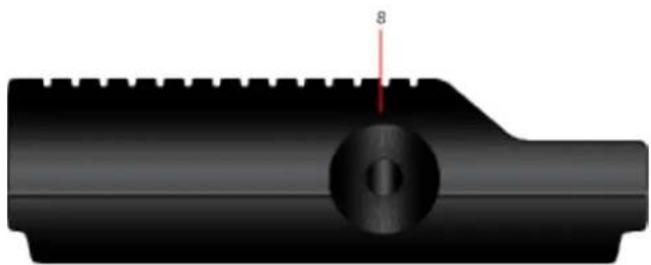
Side
natural_image
3D rendered mechanical part with a central circular feature and a red arrow labeled '8' pointing to it (no text or symbols beyond the number)- Volume dial
5686G-PRO User Guide
Step One: Prepare for Installaon
-
Uninstall all other modems * that are installed on your computer. For instrucons, refer to the documentaon for your previous modem or your computer's operang system.
-
Unplug all data, telephone, and power cords connected to your previous modem(s).
-
Shut down your computer and power it o.
-
Locate the serial port on the back of your computer. To find the serial port, look for a port labeled COM, MODEM, RS-232, [0][1], or SERIAL. Do not use the AUX, GAME, LPT, or PARALLEL ports.
Note: If your computer does not have a serial port, use a USB-to-serial cable that is compatible with your computer's operang system.
*If the previous modem was a USRobocs Courier 56K Business Modem, do not uninstall it. The Courier Lite 56K Business Modem uses the same driver as the Courier 56K Business Modem.
Step Two: Connect the Modem to the Computer
- Connect one end of the serial modem cable to modem and the other end to your computer's serial port.

natural_image
Illustration of a desktop computer tower connected to a black console unit via cable (no text or symbols visible)Step Three: Connect the Modem to an Analog Telephone Line
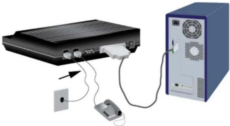
Cauon: The Courier Lite 56K Business Modem must be plugged in to an analog phone line only. Plugging your Courier Lite 56K Business Modem in to a digital phone line may damage the modem. Most oce phones are wired through digital lines. Be sure you know what type of line you have.
-
Plug one end of the telephone cord into the jack on the modem.
-
Plug the other end into an analog telephone wall jack.
natural_image
Illustration of a desktop computer setup with a monitor, tower, and telephone connected to a device (no text or symbols visible)- To connect a telephone through the modem, plug the telephone's cord into the modem's jack.
Step Four: Power Up the Modem
- Plug the power adapter into the power jack on the modem and the other end into an electrical outlet.

natural_image
Illustration of a server rack connected to a tower with power outlets and connections (no text or symbols)- Turn on the modem by switching the power switch on the top of the modem to ON. The CS LED should light.
5686G-PRO User Guide
If the CS LED does not light or if other LEDs light, make sure that only DIP switches (located on the back of the modem) 3, 5, and 8 are in the ON (down) position.

natural_image
Abstract 3D block structure with numbered blocks (1–8) on black background, no text or symbols present- Turn on your computer.
Step Five: Install the Modem Drivers
Windows operang systems should automatically install the modem driver. If the driver does not install automatically, or for other operang systems, visit http://www.usr.com/support.
Uninstallaon
Consult your computer's operang system documentaon for uninstallaon procedures.
Modem Upgrade
Upgrading your Modem
This secon contains informaon about:
- Checking your modem's software version
• Geng new operang soware
• Getting the Flash Loader application
• Use the Flash Loader application to send the new software to your modem - If the Flash Loader doesn't find your modem
- If your modem doesn't respond after flashing
- Remote ash
Checking Your Modem's Soware Version
Issuing the ATI7 command produces the following informaon to appear on your terminal screen.
| ATI7 | |
| USRobocs Courier Lite Conguraon Prole... | |
| Product type | US/Canada External |
| Product ID | 00568607 |
| Opons | V32bis,V.80,V.34+,V.90,V.92 |
| Fax Opons | Class 1,Class 2.0 |
| Clock Freq | 92.0Mhz |
| Flash ROM | 256k |
| Ram | 96k |
| Supervisor date | May 2 2018 |
| DSP date | May 2 2018 |
| Supervisor rev | V1.0.0 |
| DSP rev | OF |
| DAA rev | 3 |
| Serial Number | xxxxxxxxxxxxx |
| OK | |
Check the Supervisor and Digital Signal Processor (DSP) dates found in the screen display. These dates will determine which version of the soware your modem is using.
Geng New Operang Soware
To get the newest version of the Courier Lite 56K Business Modem's operating software, go to the customer support web site at hp://www.usr.com/support.
Geng the Flash Loader Applicaon
To ash new rmware into the Courier Lite 56K Business Modem, you must run the USRobocs Flash Loader applicaon on your computer.
To get the newest version of the Flash Loader applicaon, go to the customer support web site at hp://www.usr.com/support.
5686G-PRO User Guide
Use the Flash Loader Applicaon to Send the New Soware to Your Modem
Run the Flash Loader applicaon.
Navigate to the new soware le.
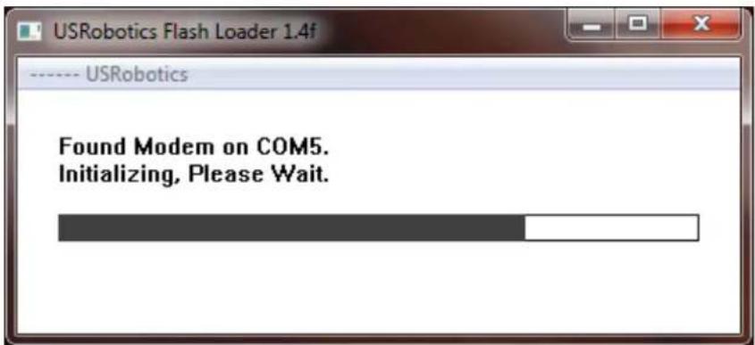
Aer you choose the soware le that you want to send, the Flash Loader will search your computer's COM ports for the Courier Lite 56K Business Modem.
Note: There must be no other active modems on any of your computer's COM ports.

5686G-PRO User Guide
Once the Flash Loader selects the COM port, it will send the le to the modem.


If the Flash Loader Doesn't Find Your Modem
If the Flash Loader doesn't nd your modem during the ash process:
- Check that your computer has no other active modems on any of its COM ports. Don't forget to disable any internal modems in your computer.
- Manually verify that the Courier Lite 56K Business Modem is active by using a serial terminal applicaon. (e.g. PuTTY, Tera Term, RealTerm, etc.) Select the COM port of the Courier Lite 56K Business Modem. Type AT and Enter. The modem should respond OK.
If the modem doesn't respond OK:
A. Check that you're using the correct COM port that your computer has assigned to the Courier Lite 56K Business Modem.
B. Check that the Courier Lite 56K Business Modem power is ON.
C. Check that the serial cable connecting the computer's serial port to the Courier Lite 56K Business Modem is wired with all the RS232 control signals. (i.e. DTR, DSR, CTS, RTS)
- Contact USR Technical Support.
If Your Modem Doesn't Respond Aer Flashing
If your modem doesn't respond after the flash process, the new software file may be corrupt. Try downloading it again from the USR support website. Then send that le to the Courier Lite 56K Business Modem using the Flash Loader.
If your modem sll doesn't respond, contact USR Technical Support.
Remote Flash
Flashing soware into a remote Courier Lite 56K Business Modem is not supported.
CONFIGURATION
Configuring DIP Switches
Locang DIP Switches
On the Courier Lite 56K Business Modem, the DIP switches are on the back of the unit. The default seng is DIP switches 3, 5, and 8 are ON (in the down posion).

Using DIP Switches to Congure your Courier Lite 56K Business Modem
| To do this | Set DIP Switch | To this seng |
| Set DTR to Normal | 1 | OFF (Default) |
| Ignore DTR | 1 | ON |
| Set verbal result code display | 2 | OFF (Default) |
| Set numeric result code display | 2 | ON |
| Disable result codes | 3 | OFF |
| Enable result codes | 3 | ON (Default) |
| Enable the echo in oine commands | 4 | OFF (Default) |
| Disable the echo in oine commands | 4 | ON |
| Enable auto answer | 5 | OFF |
| Disable auto answer | 5 | ON (Default) |
| Normal Carrier Detect | 6 | OFF (Default) |
| Carrier Detect always on | 6 | ON |
| Load Y0-Y4 conguraon that is stored in non-volale memory (NVRAM) | 7 | OFF (Default) |
| Load the &F0 conguraon from read-only memory (ROM) | 7 | ON |
| Disable AT commands | 8 | OFF |
| Enable AT commands | 8 | ON (Default) |
Accessing and Configuring the Modem Remotely
This secon contains informaon about:
• Seng Up Remote Access
- Accessing The Host
• Quing a Remote Access Session
Overview
You can set up the Courier Lite 56K Business Modem so other devices can view or change its conguraon remotely.
You should be familiar with these terms before you connue:
| Local | The device that is directly connected to the computer you are using. |
| Remote | The device at the other end of a telephone conncon. |
| Host | The Courier Lite 56K Business Modem that will be accessed and controlled by other devices. |
| Guest | The device that will access and control the host Courier Lite 56K Business Modem. |
Seng Up Remote Access
At the Host Courier Lite 56K Business Modem
- Prepare to send AT commands by putting your communications software in Terminal Mode.
- Enable remote access.
Set Register S41 for a value of 1 or greater. S41 sets the number of login aempts available to the remote user. A seng of zero allows no login aempts disabling remote access.
Example: Sending ATS41=1&W allows for 1 login attempt by a remote user.
- Set one or two remote-access passwords.
You can set two passwords to allow dierent levels of access to each Courier Lite 56K Business Modem.
| To allow guest users to | Use this command to assign a remote-access password |
| View the Courier Lite 56K Business Modem’s conguraon. | AT%P0=password |
| View and change the Courier Lite 56K Business Modem’s conguraon. | AT%P1=password |
Example: Sending AT%P1= wombat will allow a remote user to log in with the password "wombat." The user can view and change the Courier Lite 56K Business Modem's conguraon.
Note: Remote-access passwords can be up to eight alphanumeric characters long, and are not case-sensitive.
Other Remote-Access Commands
The table below is a list of remote-access conguraon commands.
| For your modem to | Command |
| Display a view-only password | AT%P0? |
| Display a view-and-change password | AT%P1? |
| Erase a view-only password | AT%P0= |
| Erase a view-and-change password | AT%P1= |
| Disable remote access enrely | ATS41=0 |
Example: Sending AT%P1= will erase the view and change password.
WARNING: If you erase the %P1 password without disabling remote access (using ATS41=0), anyone could access the Courier Lite 56K Business Modem and change its conguraon.
Accessing The Host at the Guest Device
The guest device requires no conguraon to access the host. Follow these steps:
- Be sure that the host device has enabled remote access and is set to auto-answer (ATS0=1). Know the password, if you will need one.
- Call the host device (although it doesn't matter which device originates the call).
- Aer a conncon is established, do this:
Pause 4 seconds.
Type 4 Ides: \~\~\~\~
Pause 4 seconds.
Note: The administrator of the host device can change the remote -access character using S-Register 42, and the pause duraon using S-Register 43. Refer to the S-Registers secon for more informaon.
5686G-PRO User Guide
- You should see a display similar to this:
U.S. Robocs Courier 56K Business Remote Access Session Serial Number 000000A000000001
Password (Ctrl-C to cancel)?
There is a three minute me limit for entering the password. If the number of unsuccessful login aempts exceeds the set limit, the host device returns online and refuses any further login aempts during the remainder of the conncon.
When the host accepts the password, the following message and prompt will appear on your screen:
Remote Access granted Remote->
Note: You may not be prompted for a password. If you aren't, password security is not active. The following prompt appears on your screen aer you type the four Ides:
Remote Access granted (query only) Remote->
Note: During a remote-access session, the maximum number of characters between carriage returns is 40.
Viewing and Changing the Host's Conguraon
Once you've gained guest access to a host, you can communicate with the host just as if you were entering commands from its aached computer.
Depending on your access privileges, you can use the regular set of Courier Lite 56K Business Modem AT commands.
| If you have this access privilege | You can use |
| View-only | Any of the inquiry (ATI) commands |
| View and Congure | Any of the Courier Lite 56K Business Modem commands, except those that cannot be used while online (for example, ATD or ATA). You can also use remote conguraon commands.See the next secon for examples. |
CAUTION: Be careful not to send ATZ or ATZ! or you will lose the connection!
Remote Conguraon Commands
There are special commands that can be used only during a remote-access session.
You can change the host Courier 56K Business Modem's serial port rate by using the AT%Bn command.
| To change the host Courier 56K Business Modem's serial port rate to | Command |
| 110 bps | AT%B0 |
| 300 bps | AT%B1 |
| 600 bps | AT%B2 |
| 1200 bps | AT%B3 |
| 2400 bps | AT%B4 |
| 4800 bps | AT%B5 |
| 9600 bps | AT%B6 |
| To change the host Courier 56K Business Modem's serial port rate to | Command |
| 19200 bps | AT%B7 |
| 38400 bps | AT%B8 |
| 57600 bps | AT%B9 |
| 76800 bps | AT%B10 |
| 115200 bps | AT%B11 |
| 230400 bps | AT%B12 |
Example: Sending AT%B6 will change the Courier 56K Business Modem's serial port rate to 9600 bps.
You can use the AT%Fn command to control the data format.
| To change the data format to | Command |
| No Parity (8 data bits) | AT%F0 |
| Mark parity (7 data bits) | AT%F1 |
| Odd Parity (7 data bits) | AT%F2 |
| Even parity (7 data bits) | AT%F3 |
You can use the AT%Cn command to control whether and when to apply changes to the conguraon.
| For your modem to | Command |
| Defer conguraon changes to when the call ends. | AT%C0(Default) |
| Restore the original conguraon.Use this command to cancel any changes made during remote access and restore the original conguraon. | AT%C1 |
| Force conguraon changes.Use this command to make conguraon changes take eect immediately. We do not recommend forcing changes unless it is absolutely necessary because an unreliable conncon, or even a loss of conncon, may result. | AT%C2 |
Example: Sending AT%C1 will cancel any changes made to the modem during a remote access session and restore it to the original conguraon.
Note: Even though, by default (%C0), the changes you make do not take eect until the next connection, the new configuration is reflected immediately in inquiry responses (ATIn). Commands that have been written to NVRAM (using &W) and forced congruraon changes (%C2) will not be restored to their previous sengs when you send the host AT%C1.
Aer you make changes to the host's conguraon, the remote-access prompt changes from Remote->to Remote+>.
If you restore the original conguraon using the AT%C1 command, the rst prompt is restored, assuring you the original conguraon is intact.
Quing A Remote Access Session
If you want to quit the remote access login before you have entered the password, return online by pressing
Aer you've entered the password, you can quit by sending one of these commands:
| To end the remote-access session | Command |
| And keep the conncon. | ATO |
| And end the conncon. | ATH |
| End the conncon, and reset the host modem. | ATZ |
Note: Before you disconnect, issue the ATI5 command to the remote modem and check its S41 seng. Make sure S41 is set for a value of 1 or greater. If S41 is set to 0, when you disconnect
you will not be able to access the remote modem again. To prevent this send ATS41=1&W before you disconnect.
Dial Security
This secon contains informaon about:
• Seng up Dial Security
- Maintaining Security Accounts
• What The Guest User Needs To Do
- Configuring Dial Security Remotely
• DTMF Security
Overview
Dial Security is designed to protect networks and data centers from unauthorized access.
You should be familiar with these terms before you connue:
| Local | The device that is directly connected to the computer you are using. |
| Remote | The device at the other end of a telephone conncon. |
| Host | The Courier Lite 56K Business Modem that will be accessed and controlled by other devices. |
| Guest | The device that will access and control the host Courier Lite 56K Business Modem. |
You can congure up to 5 accounts: one administrave account for you and four accounts for guest users. The account profiles are stored in the host Courier Lite 56K Business Modem's nonvolatile random access memory (NVRAM).
There are two forms of Dial Security; each will be explained later in this secon :
- Autopass
- Password Prompng
Seng up Dial Security
Here is a summary of the steps for seng up Dial Security:
- Set up an account for yourself
- Identify your account as the Administrave Account
- Set up guest-user accounts
- Enable local (host) security
- Choose a Dial Security method
- Enable Dial Security
- Acvate the Dial Security sengs
1. Set up an account for yourself
Use any of the 5 available accounts (numbered 0-4) for your account. Use the AT%An command to set up user accounts.
Note: The AT%An command is automatically written to NVRAM. It does not require you to send &W.

flowchart
graph LR
    A["Account number (0-4)"] --> B["%A command"]
    C["Password, 8 characters maximum, case-sensitive"] --> D["Password, y,y,n,5551000"]
    E["Dialback enabled? (y/n)"] --> F["Account enabled? (y/n)"]
    G["Prompt user for dialback number? (y/n)"] --> H["Specified dialback number (up to 37 ASCII characters)"]
WARNING: Do not insert spaces between commas or between elds and commas. Spaces will invalidate the command.
5686G-PRO User Guide
Dialback opons
You can set the Courier Lite 56K Business Modem to automacally dial back a certain number aer a guest modem dials in.
Note: Count your commas. There should always be at least four commas in the %A command. Do not insert spaces between commas or between elds and commas. Spaces will invalidate the command.
| To make the host Courier Lite 56K Business Modem | Command | Example |
| Hang up and then dial back a guest device at a specied number. Expect a pause of approximately 1.5 minutes before the modem dials back. You cannot alter the duraon of the pause. | AT%A0=password,y,y,n,1area code and phone number | AT%A0=wombat,y,y,n,1,8475555555 |
| Prompt you to enter a number at which to dial back a device, and then have the Courier Lite 56K Business Modem dial back the device at that number | AT%A0=password,y,y,y, | AT%A0=wombat,y,y,y, |
| Disable dialback | AT%A0=password,y,n,, | AT%A0=wombat,y,n,, |
Note: To enable Dialback, you must enable Dial Security with Prompng. See step 6.
2. Identify your account as the Administrave Account
| For your modem to | Command | Example |
| Idenfy your account as the Administrave Account | AT%L | AT%L=PW0This example sets account 0 as the Administrave Account. |
Once you set the administrave password, you cannot view or modify the guest account proles unless you enter the correct administrave password.
WARNING: Be sure to remember your administrave password. If you enable Dial Security and then forget your administrave password, you will be locked out of the Courier Lite 56K Business Modem's dial security features. You will need to restore the factory defaults by setting DIP switch 7 ON. This will erase ALL passwords and you will have to reconfigure all your accounts.
3. Set up guest-user accounts
Use the AT%An command to set up guest-user accounts in the same way you set up your administrave account. You can set up four guest accounts. Refer to the gure in step 1 regarding informaon about formang the AT%An command.
Aer you have enabled the guest accounts, make sure the guest users know their passwords and the log-in procedure.
Modifying accounts
Aer you have set up an account, you can modify each eld independently. If a eld is to remain unchanged from its original seng, just insert a comma as shown:
$$ \mathrm{AT} \% \mathrm{A1=,,,Y}, $$
The command above allows the guest user to supply a dialback number that is dierent from the one stored in the original account record.
4. Enable Local Security.
WARNING: If you do not enable Local Security, the Dial Security sengs will not be protected and other users will be able to change or erase them.
| For your modem to | Command |
| Protect the administrave password (local security enabled) | ATS53.2=1 |
Note: You must use the &W command to save the settings in NVRAM. If you don't, the next time you reset or power o the Courier Lite 56K Business Modem, Dial Security will be disabled.
5. Decide which Dial Security opon to use
You can choose from the two types of Dial Security: Autopass and Password Prompng.
Autopass
Autopass is the default form of password protecon. Autopass automates the process of logging in to the host modem, but it requires the guest and host devices to be U.S. Robocs Courier modems.
When a guest device aempts an Autopass conneccon, the guest includes the password in its V.42 error-control request. The host modem checks all the enabled passwords in its security accounts for a match.
Password Prompng
Password Prompng allows connecons with any guest device, as long as the guest user knows the correct password.
When the host has Password Prompng enabled, it asks guest users for a password. The host modem checks the received password against each of its active Security accounts.
5686G-PRO User Guide
The table below is a comparison between Autopass and Password prompting.
| When using Autopass Prompng | When using Password Prompng |
| Both the host and guest devices are made by U.S.Robocs and have Dial Security enabled. | Guest devices don’t have to support U.S.Robocs Dial Security. |
| The conncon between the Courier Lite 56K Business Modem or modems is under V.42 error control.(Refer to the Alphabec Command Summary secon for informaon about using AT&M4 or AT&M5.) | V.42 error-control conncons aren’t required. |
| If the guest includes an invalid password, the host sends an INVALID PASSWORD message and hangs up. | If the guest sends an invalid password, the host prompts twice more before disconnecng.If the guest does not send a password aer 60 seconds, the host disconnects. |
| If the guest includes a valid password, the host permits a secure conncon. | The host will sll always respond to a correct Autopass aempt. |
| If the guest did not enable Dial Security, the host will not accept the call unless prompng is enabled on the host Courier Lite 56K Business Modem. |
6. Enable Dial Security
WARNING: Before you enable Dial Security, you must set up an administrave account and password. See Steps 1 & 2.
| For your modem to enable | Command |
| Autopass Dial Security | ATS53.0=1 |
| Dial Security with Password Prompng(this also enables Autopass) | ATS53.0=1.1=1 |
| Dialback Security, enable Password Prompng and enable Dialback in each guest account | AT%An=password,y,y,y,phone numberwhere n is the account number. See the gure in previous secon, Seng Up Dial Security for more informaon. |
Example: Issuing AT%A3=wombat,y,y,y,5551234 to your modem will enable Password Prompng and Dialback for account 3, which has the password "wombat."
Note: You must use the &W command to save the sengs for Enabling Autopass Dial Security and Dial Security with Password Prompng. If you don't, the next me you reset or power o the Courier Lite 56K Business Modem, Dial Security will be disabled.
If you need a reference when seng these commands, you can use the ATI10 command. Refer to the Alphabec Command Summary secon for more informaon about the ATI10 command.
7. Send ATZ or ATZ! to acvate the Dial Security sengs.
Note: Make sure that DIP switch 7 is OFF, so the modem loads the sengs stored in NVRAM. If DIP switch 7 is ON, the sengs in ROM (&F0) are loaded, disabling dial security. You can retrieve the dial security sengs by seng DIP switch 7 OFF and reseng the Courier Lite 56K Business Modem using ATZ or by toggling the power of the modem.
Maintaining Security Accounts
Once the administrave password is set and Dial Security is enabled, the administrator is the on ly one who can access account informaon.
You can use the AT%S= and AT%E= commands to change and modify account informaon.
| For your modem to | Command |
| Access accounts by disabling local security | AT%S=administrave password |
| View account informaon, once access has been granted.Remote users may only use this command during remoteaccess sessions if local-access security is disabled. | ATI10 |
| Erase local-access password | AT%E=1 |
| Erase Autopass password | AT%E=2 |
| Erase passwords in accounts 0-4 | AT%E=3 |
| Erase phone numbers in accounts 0-4 | AT%E=4 |
| Disable Account, Dialback, and New Number elds inaccounts 0-4. | AT%E=5 |
| Edit or overwrite an individual account or an individualaccount eld | AT%An=where n is the account number.See the image in the Seng Up DialSecurity secon for more informaon. |
Example: Sending AT%E=3 erases passwords for accounts 0-4.
Note: When using the AT%S= command, the device echoes the administrave password, which is case-sensitive. Courier 56K Business Modems will accept an invalid password entry, but will lock out users from the security commands. For example, if the password is Green, but you enter GREEN, an OK is displayed. However, if you try to type a security command (for example, ATI10 to view accounts), an [ACCESS DENIED] message is displayed.
Remote Conguraon
Dial Security accounts may be configured remotely. (Refer to Configuring Dial Security Remotely at the end of this secon.)
What The Guest User Needs To Do
When guest users want to call in to the host (assuming you have enabled Dial Security by entering ATS53.0=1),
• They must know the password.
- If you have enabled Dialback, they must set their device to auto-answer.
- If the host has security enabled, get a password from the host's administrator. The password is case-sensitive, so be sure to copy it correctly.
If the host has prompting enabled and the host operator enables Dialback for your account, skip to Step 3.
- For guest users with Courier Lite 56K Business Modems (or I-Modems) only:
a) Create a security account using the password the host's administrator asked you to use. (See Seng Up Dial Security, earlier in this secon for instrucons.)
b) You need to assign the password as your Autopass password.
| For your modem to | Command |
| Assign the password as your Autopass password. | AT%V=PWn where n is the number of the account you set up. |
Example: Sending AT%V=PW3 will assign the password as an Autopass password for account 3.
c) Check to see that you set your Autopass password correctly by using the ATI10 command.
Your Autopass password appears beside AUTOPASS PASSWORD if you have done all the steps correctly.
d) Once the Autopass password is set, enable your Courier Lite 56K Business Modem's Dial Security.
| For your modem to | Command |
| Enable Dial Security | ATS53.0=1 |
CAUTION: If you do not follow an S-Register setting with &W, the setting will be retained only until the next reset or power o.
- If Dialback is enabled at the host Courier Lite 56K Business Modem's site, set your modem to answer the host Courier Lite 56K Business Modem when it dials back.
| For your modem to | Command |
| To answer the Dialback call | ATS0=1 |
- Call the host.
- Aer the call ends you can disable Auto Answer.
| For your modem to | Command |
| Disable Auto Answer | ATS0=0 |
Conguring Dial Security Remotely
The host administrator can congregate the host's security sengs remotely.
Note: At the host device, you must have previously enabled remote access and assigned a remote-access password that allows view-and-change privileges (Refer to the Accessing and Configuring the Modem Remotely section in this guide). You may want to use your administrative password as your remote-access password.
Dialing In From the Remote Site
- From the remote site, connect to the host using Dial Security. Once a connection is made, follow the instrucons for beginning a remote-access session as described in the Accessing and Conguring the Courier Lite 56K Business Modem Remotely.
- When remote access has been granted, use the AT%S= command to access the Dial Security accounts. Refer to the Maintaining Security Accounts part in this secon.
To view the security account informaon use ATI10.
- Make any configuration changes and execute them immediately by entering AT%C2.
- To end the remote session and reactivate Dial Security on the host, reset the host device by issuing ATZ.
WARNING: If you do not use the ATZ command to end a remote-access session, Dial Security will remain disabled at the host, and anyone dialing in to the host for remote access will have access to the ATI10 screen and all Dial Security accounts.
5686G-PRO User Guide
DTMF Security
DTMF (Dual Tone Mul-Frequency) Security requires a modem to go o hook when it receives a call but keep silent until it receives the valid DTMF password. Aer the modem receives the valid password, it will begin training. If the DTMF password is invalid, the modem will go on hook, and the DTE will never know there had been a call coming.
The DTMF security status and password are shown in the ATI10 screen.
DTMF security is enabled by seng the S53 bit 3, e.g. S53=8 or S53.3=1.
Using the %D command sets the DTMF security password (AT%D=PWn, n=0--4). Make sure to disable that account so no one can use the DTMF password as the Dial Security account. For example, to set local modem DTMF security password, you may use following command: AT%A0=123456,N,, then AT%D=PW0. You can change that security account later, if you like.
The DTMF password can be the combinaon of 0123456789*ABCD; the # is used as the password end sign. The maximum length of the DTMF password is eight characters.
The remote modem dial string should look like this: ATDT2625000@123456#. In this example, "123456" is the DTMF security password.
Testing the Connection
This secon contains informaon about:
• Testing the Courier Lite 56K Business Modem using AT&Tn
Overview
Your modem can perform local analog loopback and local digital loopback tests. You can use these tests to check the operations of the modem's transmitter and receiver, or to locate a problem with a remote device or a telephone line.
Testing is done by sending the AT&Tn command or by setting Register S16. Only one test can be performed at a given me. If you send a test command while the modem is in test mode, you will receive an ERROR message.
All loopback tesng conforms to ITU-T Recommendaon V.54.
Tesng the Courier Lite 56K Business Modem using AT&Tn
To perform local analog loopback and local digital loopback testing, use the AT&Tn command. You can type in your own data during tesng or use the modem's internal test paern and error detector. See the following seconds for more detailed informaon about each AT&Tn command.
| For your modem to | Command |
| End test | AT&T0 |
| Local analog loopback | AT&T1 |
| Local digital loopback | AT&T3 |
| Local analog loopback with test paern | AT&T8 |
Example: Sending AT&T3 to your Courier Lite 56K Business Modem will allow a remote user to test their conneccon to your modem.
Note: Disable error control (using the &M0 command, refer to the Alphabetic Command Summary) before tesng. If the modem is detectng errors and retransming the aected data, your results will be invalid.
Analog Loopback Tesng
Local loopback tesng checks the operaon of the Courier Lite 56K Business Modem's transmier and receiver.
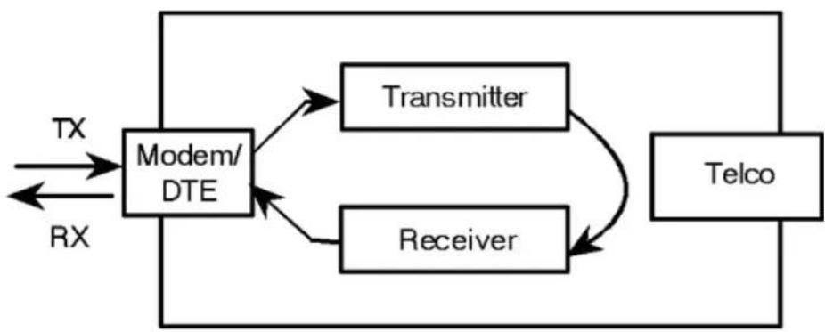
flowchart
graph TD
    A["Modem/DTE"] --> B["Transmitter"]
    A --> C["Receiver"]
    B --> D["Telco"]
    C --> D
    E["TX"] --> A
    F["RX"] --> A
Using AT&T1
- Send AT&M0&N3S14.0=0 to prepare the modem for testing.
This command disables error control, xes the conneccon rate at 2400 bps, and makes the modem return to command mode when you type +++.
5686G-PRO User Guide
- Send AT&T1 to the modem so it enters analog loopback mode. The CD status light will illuminate.
- Type any recognizable data. It will be looped back by your modem's transmitter for vericaon on your screen.
- When the test is completed, send +++ and then AT&TO to end the test.
Alternatively, you can end the test by sending ATH, or ATZ. Be careful, though, because ATZ resets the modem in addition to ending the test.
In either case, the modem responds with OK. If the modem sends an ERROR message, you have issued an invalid command.
- Send AT&M4, unless you used a reset command (ATZ).
Note: If the Courier Lite 56K Business Modem is in online command mode, sll connected to a remote modem, and you send AT&T1 or AT&T8, it drops the call, enters analog loopback mode, sends a CONNECT result, and waits for loopback characters.
Stopping a Test (AT&T0, ATS18)
To stop a test, send AT&T0 to the modem, or set Register S18 to a specified number of seconds (for example, ATS18=10). When the 10 seconds are up, the modem will stop the test automacally and return to Command Mode. Send ATH to the modem to hang up, or send ATZ to hang up and reset the modem to its defaults.
Note: If you use the S18 test timer, but in the process of testing you issue an ATZ command, S18 resets to zero and the mer is disabled. You cannot store a value for S18 in NVRAM; its power-on and reset default is always zero.
Using AT&T8
This analog loopback opon causes the Courier Lite 56K Business Modem to send an internal test paern to its transmier and loop it back to the receiver. An internal error detector counts any errors and, when the test is ended, sends the number of errors or 000 (no errors) to the screen.
Since you don't type anything during this test and the Courier Lite 56K Business Modem does not send anything to the screen, this opon veries only the Courier Lite 56K Business Modem. If there are no errors but your problem connues, it may be at the computer interface.
- Send AT&M0&N3S14.0=0 to the modem to prepare for testing.
This command disables error control, xes the conneccon rate at 2400 bps, and makes the Courier Lite 56K Business Modem return to command mode when you type +++.
- Send AT&T8 to begin the test.
The Courier Lite 56K Business Modem enters analog loopback (AL) mode, and sends a CONNECT message. The CD status light will illuminate. The modem then sends its internal test paern to the transmier, and loops the paern back to the receiver. You will not see any data on your screen.
- Send the escape code, +++, and then AT&T0 to end the test.
Alternatively, you can end the test with the S18 test mer or by sending ATH or ATZ. Be careful, because ATZ resets the modem in addition to ending the test.
In any case, the Courier Lite 56K Business Modem hangs up and returns a three-digit code, followed by OK.
| The code | Indicates |
| 000 | No errors were found |
| 255 | 255 or more errors |
| An ERROR message indicates that you issued an invalid command. | |
- Send AT&M4, unless you used a reset command (ATZ or ATZ!).
Digital Loopback Tesng (AT&T3)
This test can help you locate a problem with a remote device or with the telephone line. The gure below shows the data ow during Digital Loopback (DL) tesng.

flowchart
graph LR
    A["To DTE"] --> B["Transmitter"]
    A --> C["Receiver"]
    B --> D["Telco"]
    C --> D
    D --> E["Telco"]
    E --> F["Transmitter"]
    E --> G["Receiver"]
    F --> H["To DTE"]
    G --> H
    H --> I["TX"]
    H --> J["RX"]
    style A fill:#f9f,stroke:#333
    style I fill:#ccf,stroke:#333
    style J fill:#ccf,stroke:#333
- Send the command AT&M0&N3S14.0=0 to the modem to prepare for testing.
This command disables error control, xes the conneccon rate at 2400 bps, and makes the Courier return to command mode when you type +++.
-
Establish a conneccon with the remote device.
-
Send the Courier Lite 56K Business Modem the escape code, +++, to bring it back to Command mode.
-
Send AT&T3 to the modem to enter Digital Loopback mode.
5686G-PRO User Guide
- Have the remote user type a short message. It will be looped back by your Courier Lite 56K Business Modem's transmitter for verification on the remote user's screen. You will not see the message or any other data.
- When the remote user has completed the test, send the escape code, +++, and then AT&TO to end the test.
Alternatively, you can end the test with the S18 test mer or by sending ATH or ATZ. Be careful, because ATZ resets the modem in addition to ending the test.
In any case, the Courier Lite 56K Business Modem responds OK. If the modem sends an ERROR message, you have issued an invalid command.
- Send AT&M4, unless you used ATZ.
REFERENCE
S-Registers
Understanding Bit-Mapped S-Registers
A bit-mapped S-Register uses one number to describe a collecon of sengs. Bit -mapping allows us to pack a lot of informaon in a small space.
Bit-mapped registers are in the form of Sr.b=n, where r is the bit-mapped register; .b is the bit; n is 0 (o) or 1 (on).
The modem displays the value of an S-Register, as a decimal value between 0 and 255. The modem, however, understands the decimal value as a collecon of binary digits (bits).
How bits are mapped to decimal values
Bits can be mapped into decimal values. Each bit can be either on (1) or o (0). Eight bits create 256 unique combinaons of 1s and 0s. Each of the eight bits can be assigned a number corresponding to its posion:
b b b b b b b 7 6 5 4 3 2 1 0
Also, each bit can be assigned a value corresponding to its number (e.g., the value equals 2 to the power of the bit):
| Bit | Value |
| 7 | 128 |
| 6 | 64 |
| 5 | 32 |
| 4 | 16 |
| 3 | 8 |
| 2 | 4 |
| 1 | 2 |
| 0 | 1 |
Converng Bits to Decimal Values
Starng with a string of eight bits, assign each "1" bit a value based on its posion. Add the values to come up with the nal decimal value.
Here's an example of how bits are converted to decimal values:
01001111
| 0 | 1 | 0 | 0 | 1 | 1 | 1 | 1 |
| 0 | +64 | +0 | +0 | +8 | +4 | +2 | +1 = 79 |
Converng Decimal Values to Bits
Convert decimal values to bits by nding the largest decimal equivalent that is less than the decimal value. Subtract the decimal equivalent and mark the equivalent bit "1." Connue unl the decimal value is zero. See the example below.
113
113 - 64 = 49
01
49 -32 = 17
011
17 -16 = 1
0111
1 - 1 = 0
01110001
You can set bit-mapped S-Registers using either bits or decimal values. While it may be simpler for you to set the bits individually, your modem displays the S-Register sengs in decimal form.
Using Bits
Turning individual bits on and o is the more direct way to set bit -mapped S-Registers. To do this, specify the S-Register that you want to set and then indicate which bits you want to turn on (1) or o (0).
Example: ATS13.0=1.4=1.5=1, turns bits 0, 4, and 5 on for S -Register 13.
Using Decimal Values
An alternate way to set bit-mapped S-Registers is by adding the decimal values of the bits and entering the total.
This example, ATS13=49, sets the same value as the one in Using Bits above.
A complete list of S-Registers
| Register | Default | Funcon | ||
| S0 | 0 | Sets the number of rings on which to answer in Auto Answer mode. S0=0 disables Auto Answer. S0=1 enables Auto Answer and the Courier Lite 56K Business Modem answers on the rst ring. | ||
| S1 | 0 | Counts and stores the number of rings from an incoming call. | ||
| S2 | 43 | Stores the ASCII decimal code for the escape code character. Default character is “+”. A value of 128-255 disables the escape code. | ||
| S3 | 13 | Stores the ASCII decimal code for the Carriage Return character. Valid range is 0-127. | ||
| S4 | 10 | Stores the ASCII decimal code for the Line Feed character. Valid range is 0 -127. | ||
| S5 | 8 | Stores the ASCII decimal code for the Backspace character. A value of 128 -255 disables the Backspace key's delete funcon. | ||
| S6 | 0 | Set the number of seconds the Courier Lite 56K Business Modem waits for a dial tone. | ||
| S7 | 60 | Sets the number of seconds the Courier Lite 56K Business Modem waits for a carrier. May be set for much longer duraon if, for example, the Courier Lite 56K Business Modem is originang an internaonal conncon. | ||
| S8 | 2 | Sets the duraon, in seconds, for the pause (,) opon in the Dial command and the pause between command reexecuons (> and A> commands). | ||
| S9 | 6 | Sets the required duraon, in tenths of a second, of the remote device's carrier signal before recognition by the Courier Lite 56K Business Modem. | ||
| S10 | 14 | Sets the duraon, in tenths of a second, that the Courier Lite 56K Business Modem waits aer loss of carrier before hanging up. This guard me allows the Courier Lite 56K Business Modem to disnguish between a line hit, or other disturbance that momentarily breaks the conncon, and a true disconnect (hanging up) by the remote device. | ||
| S11 | 70 | Sets the duraon and spacing, in milliseconds, of dialed tones. | ||
| S12 | 50 | Sets the duraon, in ieths of a second, of the guard me for the escape code (+++) sequence. | ||
| S13 | 0 | Bit-mapped register. See the beginning of this secon for informaon about seng bit-mapped registers. | ||
| Bit | Value | Result | ||
| 0 | 1 | Reset when DTR drops. | ||
| 1 | 2 | Reverse normal Auto Answer operaon: On incoming RING, enter Originate Mode and look for an answer tone. | ||
| 2 | 4 | Add 250 ms pause before NO CARRIER display. | ||
| 3 | 8 | On DTR signal, autodial the number stored in NVRAM at posion 0. | ||
| 4 | 16 | At power-on/reset, autodial number stored in NVRAM at posion 0. | ||
| 5 | 32 | Reserved | ||
| 6 | 64 | Disable MNP Level 3 (used for tesng Level 2). | ||
| 7 | 128 | Hardware reset (works like powering o and then on). | ||
| S14 | 0 | Bit-mapped register (See the beginning of this secon for informaon about seng bit-mapped registers). | ||
| Bit | Value | Result | ||
| 0 | 1 | Disconnect on escape code. | ||
| 1 | 2 | Reserved | ||
| 2 | 4 | Reserved | ||
| 3 | 8 | Reserved | ||
| 4 | 16 | Reserved | ||
| 5 | 32 | Reserved | ||
| 6 | 64 | Reserved | ||
| 7 | 128 | Reserved | ||
| S15 | 0 | Bit-mapped register. ( See the beginning of this secon for informaon about seng bit-mapped registers). | ||
| Bit | Value | Result | ||
| 0 | 1 | Reserved | ||
| 1 | 2 | Reserved | ||
| 2 | 4 | Reserved | ||
| 3 | 8 | Reserved | ||
| 4 | 16 | Disable MNP Level 4; retransming the larger Lev el 4 data blocks may be a problem if you expect a great number of errors during a call. | ||
| 5 | 32 | Reserved | ||
| 6 | 64 | Some earlier 2400 bps MNP modems, not made by U.S. Robocs or Microcom, were not fully compatible with the MNP protocol. If you have diculty making a successful 2400 bps MNP conncon with a remote MNP modem, it may be because of this incompability. Set S15 to 64 and try again to make the conncon. | ||
| 7 | 128 | Reserved | ||
| S16 | 0 | Bit-mapped register. ( See the beginning of this secon for informaon about seng bit-mapped registers). For tesng, refer to theTesng the Conneconpart of the Conguraon secon. | ||
| Bit | Value | Result | ||
| 0 | 1 | Reserved | ||
| 1 | 2 | Dial Test. | ||
| 2 | 4 | Test paern. | ||
| 3 | 8 | Reserved | ||
| 4 | 16 | Reserved | ||
| 5 | 32 | Reserved | ||
| 6 | 64 | Reserved | ||
| 7 | 128 | Reserved | ||
| S18 | 0 | Test mer for soware-initiated loopback tesng (&Tn); disabled when S18 is set to 0. Used to set the duraon of tesng, in seconds, before the Courier Lite 56K Business Modem automacally mes out and terminates the test. | ||
| S19 | 0 | Sets the duraon, in minutes, for the Inacvity Timer. The mer acvates when there is no data acvity on the R232 interface, and at the meout the Courier Lite 56K Business Modem hangs up. S19=0 disables the mer. | ||
| S21 | 10 | Sets, in 10-millisecond units, the length of breaks sent from the Courier Lite 56K Business Modem to the computer or terminal. Applies to ARQ mode only. This command overwrites the current status of the +EB command, and is also overwritten by changes made by the +EB command. | ||
| S22 | 17 | Stores the ASCII code for the XON character. | ||
| S23 | 19 | Stores the ASCII code for the XOFF character. | ||
| S24 | 150 | Sets the duraon, in 20-millisecond units, between pulsed DSR signals when the Courier Lite 56K Business Modem is set to &S2 or &S3. The default is 3 seconds. | ||
| S25 | 5 | Sets DTR recognition me in 10-millisecond units. | ||
| S26 | 1 | Reserved | ||
| S27 | 0 | Bit-mapped register. ( See the beginning of this secon for informaon about seng bit-mapped registers). | ||
| Bit | Value | Result | ||
| 0 | 1 | Enable ITU-T V.21 modulaon at 300 bps for overseas calls. In V.21 mode, the Courier Lite 56K Business Modem answers both Bell 103 and V.21 calls, but only originates V.21 calls. | ||
| 1 | 2 | Reserved | ||
| 2 | 4 | Disable V.32 modulaon. | ||
| 3 | 8 | Reserved | ||
| 4 | 16 | See error control handshaking opons below. | ||
| 5 | 32 | See error control handshaking opons below. | ||
| 6 | 64 | Reserved | ||
| 7 | 128 | Unusual soware incompatibility. Some soware may not accept some result codes. This seng disables the codes and displays the 9600 code instead. The call's actual rate can be viewed on the ATI6 screen. | ||
| Error control handshaking opons: Select the total value of bits 4 and 5 | ||||
| Bit 4 | Bit 5 | Result | ||
| 0 | 0 | Complete handshaking sequence: V.42 Detecon, LAPM error control, MNP. | ||
| 16 | 0 | Disable MNP. | ||
| 0 | 32 | Disable V.42 Detecon and LAPM. | ||
| 16 | 32 | Disable Detecon phase, if you know that the remote Courier Lite 56K Business Modem does LAPM, but not the Detecon phase. | ||
| S28 | 8 | Sets the duraon in tenths of a second of the extra 3000/600 Hz answer tones sent during V.32 hand-shaking. This gives V.32 modems additional me to connect in V.32 mode before ming out.If there is diculty answering older, manually operated V.32 modems (for example, modems that require a buon to be pushed in order to dial), try lengthening the duraon of the extra tones. Seng S28 to zero eliminates the extra tones resuling in a faster connect me if, for example, the Courier Lite 56K Business Modem is set to use V.21 modulaon (300 bps) or V.23 modulaon (1200 bps). | ||
| S29 | 20 | Sets the duraon, in tenths of a second, of the V.21 answer tone. | ||
| S32 | 9 | Reserved | ||
| S34 | 0 | Bit-mapped register. See the beginning of this secon for informaon about seng bit-mapped registers. | ||
| Bit | Value | Result | ||
| 0 | 1 | Disable V.32 bis. Used for troublesomeong; Technical Support may ask you to disable V.32bis for tesng purposes. | ||
| 1 | 2 | Reserved | ||
| 2 | 4 | Reserved | ||
| 3 | 8 | Enable V.23. Required for some Brish conncons. | ||
| 4 | 16 | Reserved | ||
| 5 | 32 | Reserved | ||
| 6 | 64 | Reserved | ||
| 7 | 128 | Disable V.32 terbo. | ||
| S39 | 10 | Display transmit level in dBm with an implied minus sign. Read-only. | ||
| S41 | 0 | Sets the number of allowable remote-access login aempts, thus enabling or disabling remote access.The default seng of zero allows no remote login aempts, disabling remote access. A value of 1 or greater enables remote access. If the number of unsuccessful login aempts exceeds the limit set by this register, the Courier Lite 56K Business Modem returns online and any further login aempts during the remainder of that connecan are refused. | ||
| S42 | 126 | Stores the ASCII decimal code for the remote-access escape character. The default character is a lde (~). | ||
| S43 | 200 | Sets the duraon, in ieths of a second, of the guard me for the remote -access (~~~~) sequence. | ||
| S44 | 15 | Sets the duraon, in seconds, of the interval between losing carrier and reestablishing a connecan. | ||
| S51 | 0 | Bit-mapped register. See the beginning of this secon for informaon about seng bit-mapped registers. | ||
| Bit | Value | Result | ||
| 0 | 1 | Reserved | ||
| 1 | 2 | Reserved | ||
| 2 | 4 | Reserved | ||
| 3 | 8 | Reserved | ||
| 4 | 16 | Reserved | ||
| 5 | 32 | Reserved | ||
| 6 | 64 | Disable Selectve Reject | ||
| 7 | 128 | Reserved | ||
| S53 | 126 | Bit-mapped register. ( See the beginning of this secon for informaon about seng bit-mapped registers). | ||
| Bit | Value | Result | ||
| 0 | 1 | Dial security enabled. | ||
| 1 | 2 | Promptng enabled. | ||
| 2 | 4 | Local-access password protecon enabled. | ||
| 3 | 8 | DTMF security enabled. | ||
| 4 | 16 | Reserved | ||
| 5 | 32 | Reserved | ||
| 6 | 64 | Reserved | ||
| 7 | 128 | Reserved | ||
| S54 | 64 | Symbol rate bit-mapped register used primarily by Technical Support for debugging purposes. | ||
| Bit | Value | Result | ||
| 0 | 1 | Disable 2400 symbol rate. | ||
| 1 | 2 | Disable 2743 symbol rate. | ||
| 2 | 4 | Disable 2800 symbol rate. | ||
| 3 | 8 | Disable 3000 symbol rate. | ||
| 4 | 16 | Disable 3200 symbol rate. | ||
| 5 | 32 | Disable 3429 symbol rate. | ||
| 6 | 64 | Disable Call Indicate (CI). | ||
| 7 | 128 | Disable V.8. | ||
| S55 | 0 | Reserved | ||
| S56 | 0 | Bit-mapped register primarily used by Technical Support for debugging purposes. | ||
| Bit | Value | Result | ||
| 0 | 1 | Reserved | ||
| 1 | 2 | Reserved | ||
| 2 | 4 | Reserved | ||
| 3 | 8 | Reserved | ||
| 4 | 16 | Reserved | ||
| 5 | 32 | Disable V.34+ | ||
| 6 | 64 | Disable V.34. | ||
| 7 | 128 | Disable V.FC. | ||
| S58 | 0 | Bit-mapped register. (See the beginning of this secon for informaon about seng bit-mapped registers.) | ||
| Bit | Value | Result | ||
| 0 | 1 | Reserved | ||
| 1 | 2 | Reserved | ||
| 2 | 4 | Reserved | ||
| 3 | 8 | Reserved | ||
| 4 | 16 | Reserved | ||
| 5 | 32 | Enables/Disables V.90 | ||
| 6 | 64 | Disables V.92 funcons | ||
| 7 | 128 | Reserved | ||
| S59 | 0 | Reserved | ||
| S69 | 0 | Bit-mapped register. (See the beginning of this secon for informaon about seng bit-mapped registers). | ||
| Bit | Value | Result | ||
| 0 | 1 | Disable external Plug and Play | ||
| 1 | 2 | Enable Auto Redial | ||
| 2 | 4 | Reserved | ||
| 3 | 8 | Reserved | ||
| 4 | 16 | Reserved | ||
| 5 | 32 | Reserved | ||
| 6 | 64 | Reserved | ||
| 7 | 128 | Reserved | ||
| S70 | 0 | Bit-mapped Register. (See the beginning of this secon for informaon about seng bit-mapped registers.) | ||
| Bit | Value | Result | ||
| 0 | 1 | Enable recognition of Ring A | ||
| 1 | 2 | Enable recognition of Ring B | ||
| 2 | 4 | Enable recognition of Ring C | ||
| 3 | 8 | Enable recognition of Ring D | ||
| 4 | 16 | Enable recognition of Ring E | ||
| 5 | 32 | Reserved | ||
| 6 | 64 | Reserved | ||
| 7 | 128 | Reserved | ||
| S71 | 0 | RCID request delay (1/200 sec) | ||
| S72 | 0 | Bit-mapped Register. (See the beginning of this secon for informaon about seng bit-mapped registers.) | ||
| Bit | Value | Result | ||
| 0 | 1 | # of requests | ||
| 1 | 2 | # of requests | ||
| 2 | 4 | # of requests | ||
| 3 | 8 | Request duraon * 10 mS | ||
| 4 | 16 | Request duraon * 10 mS | ||
| 5 | 32 | Request duraon * 10 mS | ||
| 6 | 64 | Request duraon * 10 mS | ||
| 7 | 128 | Request duraon * 10 mS | ||
| S73 | 0 | Bit-mapped Register. (See the beginning of this secon for informaon about seng bit-mapped registers.) | ||
| Bit | Value | Result | ||
| 0 | 1 | Request level | ||
| 1 | 2 | Request level | ||
| 2 | 4 | Request level | ||
| 3 | 8 | Request pause * 10 mS | ||
| 4 | 16 | Request pause * 10 mS | ||
| 5 | 32 | Request pause * 10 mS | ||
| 6 | 64 | Request pause * 10 mS | ||
| 7 | 128 | Request pause * 10 mS | ||
Alphabetic Command Summary
This secon contains an alphabec lisng of the AT commands to which the modem will respond.
Default sengs are bold.
- Basic Command Set
- Ampersand (&) Command Set
• Percent (%) Command Set
• Octothorpe (#) Command Set
• V.80/V.250 Command Set
• Additional V.92 Commands
Basic Command Set
| Command | Funcon | |
| Display help for the Basic command set. | ||
| +++ | Escape code. Once your modem is online with another device, the only command it recognizes is an escape code of three typed plus signs, which forces the modem back to Command mode. Do the following when issuing the command:1. Wait 1 second aer sending the last item of data.2. Type +++3. Wait 1 second before typing any data.When you type +++, the modem will either hang up or stay on line, depending on how you set S14. | |
| > | Repeat command. If you include the repeat command in the Dial string, the modem will dial the number and wait 60 seconds for a carrier.If the line is busy, the modem will pause for 2 seconds and then redial. The modem makes a maximum of 10 aempts. | |
| A/ | Reexecute the last-issued command. DO NOT type AT or press ENTER. | |
| A> | Repeat the last-issued command unl canceled by pressing any key. DO NOT type AT or press Enter. | |
| AT | Aenon prex: informs a modem that a command is coming. AT must precede all commands except A/, A>, and +++. | |
| A | Force a modem to answer when it is not receiving an incoming call. | |
| Bn | Set handshaking opons. | |
| B0 | ITU-T V.25 answer sequence; required to answer all V.34-type and overseas calls. | |
| B1 | Bell answer tone; use if the modem is not required to answer V.34-type calls. | |
| With the excepon of the Dial opons, modem ignores any commands issued aer D in the same command string. | ||
| Dn | Dial a phone number and issue other oponal commands.The numbers 0-9 are accepted. The maximum number of characters allowed is 36, including the AT prex, punctuaon, and spaces. | |
| Oponal parameters: | ||
| P | Dial using pulses. | |
| T | Dial using tones. | |
| , | (Comma) Pause for 2 seconds (or the me in S-Register 8). | |
| ; | (Semicolon) Remain in Command mode aer dialing. | |
| " | Dial the leers that follow. Example, ATDT1800"DIAL USR" same as ATDT18003425877. | |
| W | Wait for a second dial tone before connuing to dial (with X3 or higher). | |
| @ | Wait for an answer (with X3, X4, or X7). | |
| / | Pause for 125 milliseconds. | |
| R | Reverse frequencies. Use this command when calling an originate-only modem. It forces the modem to dial out at the answer frequency. | |
| ! | Flash the switchhook (o hook 0.5 seconds, on hook 0.5 seconds, then o hook). Use ! when other modems share the line. | |
| L? | Display the last-dialed number. | |
| L | Dial the last-dialed number. | |
| Sn | Dial the number stored in memory at posion n, where n = 0-4. Store the number in memory using the &Z command. | |
| Display help for the dial commands. ATD | ||
| En | Command mode echo. Enables or disables the display of your typed commands. | |
| E0 | Command mode echo OFF. Your typing will not appear on the screen. | |
| E1 | Command mode echo ON. Your typing will appear on the screen. | |
| If double characters appear on the screen, both the modem's local echo and your soware's local echo are on. | ||
| Fn | Online local echo. If ON, a modem displays on your screen the data that it is transming to another modem. | |
| F0 | Online echo ON. (Somemes called half duplex.) | |
| F1 | Online echo OFF. (Somemes called full duplex.) | |
| Hn | Go on or o hook. | |
| H0 | Go on hook (hang up). | |
| H1 | Go o hook (pick up). | |
| In | Query the modem. | |
| I0 | Displays the product code. | |
| I1 | Displays checksum. | |
| I2 | Displays RAM TEST. | |
| I3 | Displays the banner (product name). | |
| I4 | Display current modem sengs. | |
| I5 | Display sengs stored in NVRAM. | |
| I6 | Display stascs for the last call. | |
| I7 | Display product conguraon. | |
| I8 | Lists phone numbers with redial restricons. | |
| I9 | Displays modem's Plug and Play ID. | |
| I10 | Display dial security account status informaon. | |
| I11 | Display link diagnoses report. | |
| I15 | Display caller ID informaon. | |
| I16 | Display channel probe report. | |
| Mn | Control when the speaker sounds | |
| M0 | The speaker is always o. | |
| M1 | The speaker is on unl the call is negoated. | |
| M2 | The speaker is always on. | |
| M3 | The speaker turns on aer the last digit is dialed and stays on unl the call is negoated. | |
| On | Return online. Use with the escape code (+++) to toggle between command and online modes. | |
| O0 | Return online (normal). | |
| O1 | Return online and retrain. Use O1 if there were errors in a non -ARQ data transfer. | |
| Qn | Enable or disable the display of result codes. | |
| Q0 | Display result codes. | |
| Q1 | Suppress result codes (quiet). | |
| Q2 | Suppress result codes when answering. | |
| S | Display help screens for the S-Registers. | |
| Sr=n | Set S-Register value: r is any S-Register; n must be a decimal number between 0 and 255. | |
| Sr.b=n | Set a bit-mapped register: r is the S-register, b is the bit, and n is 0 (o) or 1 (on). | |
| Sr? | Query contents of S-register r. | |
| Refer to the S-Registers secon for a lisng of all the S-Registers. | ||
| Vn | Display result codes in words or numbers. | |
| V0 | Display result codes in numeric form. | |
| V1 | Display result codes in verbal form. | |
| Xn | Control the amount of informaon displayed in the result codes. The default is X7 (all codes except 12/VOICE). The modem doesn’t try to detect signals if it isn’t set to report them.For more detailed informaon, refer to the Result Code Meanings and Sets secon of the appendix. | |
| X3 | Ignore Dial Tone | |
| X4 | Microso default | |
| X7 | Courier Lite 56K Business Modem default | |
| Yn | Control which user prole or factory prole is recalled when the modem is reset. | |
| Y0 | At reset use stored profile 0 | |
| Y1 | At reset use stored profile 1 | |
| Y2 | At reset use factory profile 0 (&F0) | |
| Y3 | At reset use factory profile 1 (&F1) | |
| Y4 | At reset use factory profile 2 (&F2) | |
| Zn | Soware reset. | |
| Z0 | If DIP Switch 7 is ON (factory sengs), recall the &F0 conguraon template (no ow control). If DIP switch 7 is OFF, recall the prole selected by the Y command. | |
| Z1 | Reset using stored profile 0 | |
| Z2 | Reset using stored profile 1 | |
| Z3 | Reset using factory profile 0 | |
| Z4 | Reset using factory profile 1 | |
| Z5 | Reset using factory profile 2 | |
| Z! | Complete hardware reset | |
Ampersand (&) Command Set
| Command | Funcon | |
| &$ | Display help for the ampersand (&) command set. | |
| &An | Enable or disable the display of additional result code subsets. (Also, see the Xn command.) | |
| &A0 | Do not display ARQ result codes. | |
| &A1 | Display ARQ result codes. | |
| &A2 | In addition to ARQ result codes, display V.32, V.FC, V.34, V.90, or V.92 modulaon indicator. | |
| &A3 | In addition to ARQ and modulaon indicators, display an error control indicator (LAPM, MNP, SYNC, or NONE) and a data compression type (V42 bis or MNP5). | |
| &Bn | Set the serial port rate to variable or xed. | |
| &B0 | Variable: The serial port rate adapts to match the speed of the conncon. | |
| &B1 | Fixed: The modem always communicates with your computer at the rate at which you have set, regardless of the conncon rate. | |
| &B2 | When answering calls, use the xed rate for ARQ calls and variable rates for non-ARQ calls. | |
| The serial port rate should be equal to or higher than the &Nn rate. | ||
| &Cn | Controls how the modem sends a Carrier Detect (CD) signal to your computer. | |
| &C0 | CD always ON, even if the modem is not on line. | |
| &C1 | Normal operaons. The modem sends a CD signal when it connects with another modem and drops the CD when it disconnects. | |
| &Dn | Control how the modem responds to Data Terminal Ready (DTR) signals. | |
| &D0 | DTR is always ON (ignored). | |
| &D1 | If issued before connecng with another device, the Courier Lite 56K Business Modem can enter online Command mode during a call by dropping DTR.&D1 funcons similarly to the escape code (+++).Return online with the On command, or hang up with the Hn command. | |
| &D2 | Normal DTR operaons. The modem will not accept commands unless your computer sends a DTR signal. Dropping DTR ends a call. | |
| &D3 | Modem resets with DTR toggle. | |
| &Fn | Load one of the three conguraon templates that are stored permanently in read-only memory. Refer to the Flow Control Template secon for the sengs for each template.To load a template into current memory, enter AT&Fn. To write a template to NVRAM, enter AT&Fn&W0 or AT&Fn&W1.If DIP switch 7 is ON, &F0 is always loaded into memory at power-on or reset. | |
| &F0 | Load No Flow Control template sengs. | |
| &F1 | Load Hardware Flow Control template sengs. | |
| &F2 | Load Soware Flow Control template sengs. | |
| &Gn | Set guard tones for internaonal calls. | |
| &G0 | No guard tone. Use this in the United States and Canada. | |
| &G1 | This sets a 550 Hz guard tone, and is used in some European countries. | |
| &G2 | This sets an 1800 Hz guard tone, and is used in the U.K. and some Commonwealth countries. &G2 requires the B0 seng. | |
| &Hn | Transmit data ow control. Prevents the modem's buer for data transmied to the modem by its aached computer from overowing. | |
| &H0 | Disable transmit data ow control. | |
| &H1 | Use hardware ow control. Requires that your computer and soware support Clear to Send (CTS) at the EIA-232 interface. | |
| &H2 | Use soware ow control. Requires that your soware support XON/XOFF signaling | |
| &H3 | Use both hardware and soware ow control. If you are unsure about what your equipment supports, select this opon. | |
| &In | Received data soware ow (XON/OFF) control. | |
| &I1 | The modem acts on your typed XON/XOFF commands, Ctrl-S or Ctrl-Q, and passes them to the remote device. | |
| &I2 | The modem acts on your XON/XOFF commands, but removes them from the data stream instead of passing them to the remote device. This is the recommended seng for ARQ mode. | |
| &Kn | Enable or disable data compression. This command overwrites the current status of the +DCS and +DS commands, and is also overwritten by changes made by the +DCS and +DS commands. | |
| &K0 | Disable data compression. | |
| &K1 | Use auto-enable/disable. The modem enables compression if the serial port rate is xed (&B1) and disables compression if the serial port rate follows the conncon rate (&B0) because compression oers no throughput advantage when the serial port and conncon rates are equal; in fact, compression may degrade throughput. | |
| &K2 | Always enable data compression. | |
| &K3 | Selectve data compression. The modem negoates only for V.42 bis compression, and disables MNP Level 5 (MNP5) compression. Use this seng to transfer compressed les. | |
| &Mn | Enable ARQ (error control) protocols. Both your modem and the remote device must use the same protocol. | |
| &M0 | Normal mode, no error control. Due to the nature of phone line channels, this is never recommended for calls above 2400 bps. | |
| &M4 | Normal/ARQ mode. If an ARQ conncon isn't made, the modem operates in Normal mode as though it were set to &M0. | |
| &M5 | ARQ asynchronous mode. The modem hangs up if an ARQ conncon cannot be made. | |
| Command | Funcon | ||
| &Nn | Sets highest xed link speed. | ||
| &Un | Sets lowest xed link speed. | ||
| n=0 | Variable rate. The modem negoates with the remote device for the highest possible connecon rate, depending on the capabilities of the remote device. | ||
| n=1-38 | Fixed rate. The modem connects only if the remote device is operang at the same rate or higher.The connecon rate should be lower than or equal to the serial port rate. | ||
| n=1 | 300 bps | ||
| n=2 | 1200 bps | ||
| n=3 | 2400 bps | ||
| n=4 | 4800 bps | ||
| n=5 | 7200 bps | ||
| n=6 | 9600 bps | ||
| n=7 | 12000 bps | ||
| n=8 | 14400 bps | ||
| n=9 | 16800 bps | ||
| n=10 | 19200 bps | ||
| n=11 | 21600 bps | ||
| n=12 | 24000 bps | ||
| n=13 | 26400 bps | ||
| n=14 | 28800 bps | ||
| n=15 | 31200 bps | ||
| n=16 | 33600 bps | ||
| n=17 | 28000 bps | ||
| n=18 | 29333 bps | ||
| n=19 | 30666 bps | ||
| n=20 | 32000 bps | ||
| n=21 | 33333 bps | ||
| n=22 | 34666 bps | ||
| n=23 | 36000 bps | ||
| n=24 | 37333 bps | ||
| n=25 | 38666 bps | ||
| n=26 | 40000 bps | ||
| n=27 | 41333 bps | ||
| n=28 | 42666 bps | ||
| n=29 | 44000 bps | ||
| n=30 | 45333 bps | ||
| n=31 | 46666 bps | ||
| n=32 | 48000 bps | ||
| n=33 | 49333 bps | ||
| n=34 | 50666 bps | ||
| n=35 | 52000 bps | ||
| n=36 | 53333 bps | ||
| n=37 | 54666 bps | ||
| n=38 | 56000 bps | ||
| &Pn | Enable pulse dial. | ||
| n=0 | Pulse dial disabled | ||
| n=1 | Austria, Czechoslovakia, Denmark, Finland, Germany, Italy, Netherlands, South Africa (Second opon for Asia, France, Korea, Norway, South Africa) | ||
| n=2 | Australia, Asia, Belgium, France, Ireland, Korea, Portugal, South Africa, Spain | ||
| n=3 | Norway | ||
| n=5 | Japan | ||
| n=6 | Sweden | ||
| n=7 | (Second opon for Australia) | ||
| &Rn | Received data (RTS) hardware ow control. | ||
| &R1 | Ignore RTS. This seng is required if your computer or terminal or soware does not support RTS. | ||
| &R2 | Enable hardware ow control of received data. The modem sends data to the computer only upon receipt of the RTS signal. | ||
| &Sn | Send the computer a Data Set Ready (DSR) signal via the EIA-232 interface. | ||
| &S0 | DSR is always ON (override). | ||
| &S1 | In Originate mode: Send DSR aer dialing, on detecon of the remote device's answer tone. In Answer mode: Send DSR aer sending an answer tone. | ||
| &S2 | When Carrier is lost, send a pulsed DSR signal with Clear to Send (CTS) following Carrier Detect (CD). This opon is for specialized equipment such as automac callback units. | ||
| &S3 | Same as &S2, but without the CTS signal. | ||
| &S4 | Send the computer DSR at the same me as CD. | ||
| &S5 | Send DSR normally, and follow CTS with CD. | ||
| &Tn | Test the modem. | ||
| &T0 | End tesng. | ||
| &T1 | Local analog loopback | ||
| &T3 | Local digital loopback | ||
| &T8 | Local analog loopback with test paern | ||
| &Wn | Write the current sengs to NVRAM. | ||
| &W0 | Store current conguraon to prole 0. | ||
| &W1 | Store current conguraon to prole 1. | ||
| &Yn | Break handling. This command lets you send a break to stop data transfer without disconnecng. This command overwrites the current status of the +EB command, and is also overwrien by changes made by the +EB command. | ||
| &Y0 | Enter on-line command mode. Returning to data mode sends break. | ||
| &Y1 | Destrucve, expedited. | ||
| &Y2 | Nondestructive, expedited. | ||
| &Y3 | Nondestructive, unexpedited; the modem sends a break-in-sequence with data received from your computer or terminal. | ||
| If the call is under data compression, destructive breaks cause both modems to reset their data compression tables. When transmission resumes, the modems build new tables, and the result is temporary lower-than-normal throughput. | |||
| &Zn=s | Store up to 5 numbers in NVRAM, where n is the position 0-4 in NVRAM, and s is the phone number string. The number string may be up to 36 characters long, including any Dial command opons.Example: AT&Z2=555-6789In the following example, &M0 (no error control) is inserted before the Dial command. Example: AT&M0 DS2 | ||
| This command funcons dierently when Dial Security is enabled.Also, do not include modem sengs in the &Zn string. If the call requires a special seng, insert it in the command string before the DSn command. | |||
| Command | Funcon |
| &Zn=L | Stores the last-dialed number in posion n. |
| &Zn? | Display the phone number stored in NVRAM at posion n (where n = 0 -4). |
Percent (%) Command Set
| Command | Funcon | |
| %$ | Display help for the percent (%) command set. | |
| %An | Create and configure security accounts. Refer to theDial Securitysection. | |
| %Bn | Remotely congregate a modem's serial port rate. | |
| %B0 | 110 bps | |
| %B1 | 300 bps | |
| %B2 | 600 bps | |
| %B3 | 1200 bps | |
| %B4 | 2400 bps | |
| %B5 | 4800 bps | |
| %B6 | 9600 bps | |
| %B7 | 19200 bps | |
| %B8 | 38400 bps | |
| %B9 | 57600 bps | |
| %B10 | 76800 bps | |
| %B11 | 115200 bps | |
| %B12 | 230400 bps | |
| %Cn | Remote congruraon control. | |
| %CO | Defer congruraon changes until the call is ended. Changes take eect for ensuing conncons. | |
| %C1 | Cancel congruraon changes and restore the original congruraon. | |
| Using %C1 will not reverse any changes that you wrote to NVRAM (with &W) or forced (with %C2). | ||
| %C2 | Force congruraon changes to take eect immediately. | |
| We recommend against forcing congruraon changes unless it is absolutely necessary. An unreliable conncon, or loss of conncon, may result. | ||
| %D= | Set a DTMF password. Refer to theDial Security secon. | |
| %E=n | Erase security sengs. | |
| %E=1 | Erase local-access password. | |
| %E=2 | Erase Autopass password. | |
| %E=3 | Erase passwords in accounts 0-4. | |
| %E=4 | Erase phone numbers in accounts 0-4. | |
| %E=5 | Disable Account, Dialback, and New Number elds in accounts 0-4. | |
| %Fn | Remotely congregate another device's data format. | |
| %F0 | No parity, 8 data bits. | |
| %F1 | Mark parity, 7 data bits. | |
| %F2 | Odd parity, 7 data bits. | |
| %F3 | Even parity, 7 data bits. | |
| %L= | Set a local-access password. Refer to theDial Security secon. | |
| %Pn= | Disable password security (n=0 or n=1) when no character follows the equal sign. | |
| %Pn=s | Set the following password (s) for viewing privileges only (n = 0), or view and conguraon privileges (n= 1). | |
| %Pn? | Display password n. | |
| %S=n | Access the security accounts. Does not disable security. | |
| %T | Enable the recognition of tone frequencies of analog dialing devices. %T is meant primarily for use with network applicaons, but may also be integrated into certain soware programs. For example, %T could be used in a security program to identify incoming tone security codes.To return the modem to Command mode, press any key or drop the computer's or terminal's DTR signal. The modem responds OK. | |
| %V=PWn | Assign the password in account n in your modem's security account as your Autopass password | |
Octothorpe (#) Command Set
| Command | Funcon | |
| #$ | Display the help panels for the octothorpe (#) command set. | |
| #CID=n | Controls the caller ID sengs. | |
| #CID=0 | Disable caller ID detecon and reporng. | |
| #CID=1 | Enable caller ID with formaed output. | |
| #CID=2 | Enable caller ID with unformaed output. | |
| #CID=3 | Enable caller ID with formaed output and name suppressed. | |
| #CID=4 | Enable caller ID but do not transmit the informaon to your computer - retain it in the modem's memory. | |
| #CID? | Display the current caller ID sengs. | |
| #CID=? | Display the caller ID acons that are available. | |
V.80/V.250 Command Set
| Command | Funcon | |
| +DCS=n,m | Use this command to congregate the available compression algorithms. The n parameter enables or disables V.42bis, and the m parameter enables or disables V.44. This command works in conjuncon with the &K command, and the result of either the &K command or the +DCS command replaces the current data compression conguraon. | |
| n=0 | Disable V.42bis. | |
| n=1 | Enable V.42bis. | |
| m=0 | Disable V.44. | |
| m=1 | Enable V.44. | |
| m=2 | Enable V.44 for V.92 servers only. | |
| +DCS? | Display current +DCS seng. | |
| +DCS=? | Display list of valid +DCS sengs. | |
| +DR=n | Use this command to enable or disable the compression report. If the compression report is enabled, the +DR:intermediate result code reports the current data compression type. It is issued aer the error control report (+ER) and before the nal result code (e.g., CONNECT). | |
| n=0 | Disable the compression report. | |
| n=1 | Enable the compression report. | |
| +DR? | Display current +DR seng. | |
| +DR=? | Display list of valid +DR sengs. | |
| +DS=n,m,l,k | Set V.42 compression method. This command overwrites the current status of the &K command, and is also overwritten by changes made by the &K command. | |
| n=0 | Do not negotiate V.42bis compression. | |
| n=3 | Modem accepts V.42bis compression in both direcon. | |
| m=0 | Don't disconnect if V.42 negoans fail. This parameter is always set to 0. | |
| l=2048 | Diconary size, always set to 2048. | |
| k=32 | String length, always set to 32. | |
| +DS? | Display current +DS seng. | |
| +DS=? | Display list of valid +DS sengs. | |
| +EB=n,m,l | Set break handling method. This command overwrites the current status of the &Y command and S21, and is also overwritten by changes made by the &Y command and S21. | |
| n=0 | Enter on-line command mode. Returning to data mode sends break. | |
| n=1 | Nonexpedited, nondestructive. | |
| n=2 | Expedited, nondestructive. | |
| n=3 | Expedited, destructive. | |
| m=0 | Break length is med. This parameter is always set to 0. | |
| l=10-90 | Set break length in 10 millisecond units, in steps of 10. | |
| +EB? | Display current +EB seng. Break length is displayed in milliseconds. | |
| +EB=? | Display list of valid +EB sengs. | |
| +ER=n | Set error control reporting. The +ER: intermediate result code reports the current error control type, issued aer the modulaon report and before the data compression report. | |
| n=0 | Disables the error control report. | |
| n=1 | Enables the error control report. | |
| +ER? | Display current +ER seng. | |
| +ER=? | Display list of valid +ER sengs. | |
| +ETBM=n,m,l | Set call terminaon buer management. 0,0,0 is the only valid combinaon, which means the modem discards all buered data when the call is terminated. | |
| n=0 | This parameter is always set to 0. | |
| m=0 | This parameter is always set to 0. | |
| l=0 | This parameter is always set to 0. | |
| +ETBM? | Display current +ETBM seng. | |
| +ETBM=? | Display list of valid +ETBM sengs. | |
| +ILRR=n | Set local rate reporg. Use this command to display or hide the local rate report result code. The rate report is an intermediate result code , transmied aer any modulaon, error control, or data compression reports, and before the nal result code (e.g., CONNECT). | |
| n=0 | Disables the local rate report. | |
| n=1 | Enables the local rate report. | |
| +ILRR? | Display current +ILRR seng. | |
| +ILRR=? | Display list of valid +ILRR sengs. | |
| +MR=n | Set modulaon reporg mode. Use this command to hide or display the modulaon report. The modulaon report is an intermediate result code, transmied aer the modulaon and the rate have been determined , and before any error control or data compression reports or the nal result code (e.g., CONNECT). | |
| n=0 | Turns o the modulaon report. | |
| n=1 | Turns on the modulaon report. | |
| +MR? | Display current +MR seng. | |
| +MR=? | Display list of valid +MR sengs. | |
| +MS=n,m,l,k,j,i | Set modulation selection. Use this command to set the modem's modulation, the maximum transmission and recepon rates, and the status of automac modulaon negoaoon. | |
| n=V92 | V.92 | |
| n=V90 | V.90 | |
| n=V34 | V.34 | |
| n=V32B | V.32bis | |
| n=V32 | V.32 | |
| n=V22B | V.22bis | |
| n=V.22 | V.22 | |
| n=Bell212A | Bell 212A | |
| n=V23C | V.23, constant carrier, asymmetric FDM | |
| n=V21 | V21 | |
| m=0 | Disable automac modulaon negoaoon. | |
| m=1 | Enable automatic modulation negotiation.If a value is specied for k, automac rate selecon is disabled and the modem aempts to connect at the specied rate. | |
| l=0 | Minimum transmission rate, always set to 0. | |
| k=0 | Use automac transmission rate selecon. | |
| k=300-33600 | Maximum transmission rate. Default=31200 | |
| V34: 2400-33600 in steps of 2400 | ||
| V32bis: 4800-19200 in steps of 2400 | ||
| V32: 4800-14400 in steps of 2400 | ||
| V22bis: 2400 | ||
| V22: 2200 | ||
| V23C, Bell212A: 1200 | ||
| V.21, Bell103: 300 | ||
| j=0 | Minimum recepon rate, always set to 0. | |
| i=0 | Use automac recepon rate selecon. | |
| i=300-56000 | Maximum recepon rate. Default=31200 | |
| +MS? | Display current +MS seng. | |
| +MS=? | Display list of valid +MS sengs. | |
+p Command Set (V.92 Commands)
| Command | Funcon | |
| +p$ | Display help for the +p command set. | |
| +pCW=n | Controls call waing. | |
| +pCW=0 | Process call waing | |
| +pCW=1 | Disconnect on call waing | |
| +pCW=2 | Ignore call waing | |
| +pIG=n | Controls PCM upstream. | |
| +pIG=0 | Enable PCM upstream | |
| +pIG=1 | Disable PCM upstream | |
| +pMH=n | Controls Modem on Hold. | |
| +pMH=0 | Enable Modem on Hold | |
| +pMH=1 | Disable Modem on Hold | |
| +pMHD | Send DTMF during MOH | |
| +pMHR | Request Modem on Hold. | |
| +pMHT? | Display Modem on Hold meout. | |
| +pQC=n | Controls phases of QC. | |
| +pQC=0 | Enable phase 1 and phase 2 of QC | |
| +pQC=1 | Disable phase 1 and enable phase 2 of QC | |
| +pQC=3 | Disable phase 1 and phase 2 of QC | |
| +pSS=n | Controls short sequences. | |
| +pSS=0 | Modem decides on short sequences | |
Flow Control Template
• Hardware Flow Control
- Soware Flow Control
- No Flow Control
Hardware Flow Control
The table below lists the Hardware flow control template. To load this template send AT&F1 to your modem.
| NVRAM Opons | Seng | Descripon |
| Handshake opon | B0 | ITU-T answer sequence |
| Command mode echo | E1 | Enabled |
| Online local echo | F1 | Disabled |
| Speaker control | M1 | ON during dial through connect |
| Result codes | Q0 | Enabled |
| Verbal or numeric result codes | V1 | Verbal result codes |
| Result code subset | X7 | Extended. Includes all codes except VOICE |
| Prole used at reset | Y0 | At reset use stored prole 0 |
| Protocol response codes | &A3 | Full protocol codes |
| Serial port rate select | &B1 | Serial port rate xed higher than connect rate |
| Guard tone | &G0 | U.S./Canada |
| Transmit data hardware ow control | &H1 | Hardware ow control |
| Received data soware ow control | &I2 | No pass-thru |
| Analog data compression | &K1 | Enabled |
| Error control/sync | &M4 | Normal/error control |
| Highest Link rate select | &N0 | Variable |
| Pulse dialing type | &P1 | U.S., Canada, and other countries |
| Received data hardware ow control | &R2 | Enabled |
| Data Set Ready | &S0 | Always on |
| Remote Digital Loopback (RDL) | &T5 | Deny RDL |
| Lowest Link rate select | &U0 | Variable |
| Break handling | &Y1 | Clear buer, send immediately |
| Caller ID | #CID=0 | Caller ID disabled |
| Set Compression Method | +DCS=1,0 | Enable V.42bis, Disable V.44 |
| Set Compression Report Mode | +DR=0 | Disable the report |
| Set V.42 Compression Method | +DS=3,0,2048,32 | Accept V.42bis, don’t disconnect if fail, 2048 diconary, 32 string |
| Set Break Handling Method | +EB=3,0,10 | Expedited, destrucve, 100mS |
| Set Error Control Reporng | +ER=0 | Disable the report |
| Set Call Terminaon Buer Management | +ETBM=0,0,0 | Flush all buers on call terminaon |
| Set Local Rate Reporng | +ILRR=0 | Disable the report |
| Set Modulaon Reporng Mode | +MR=0 | Disable the report |
| Set Modulaon Selecon | +MS=V92,1,0,31200,0,56000 | V.92, auto, auto, 31.2k max tx,56k max rx |
| Word length* | 8 | |
| Parity* | 0 | None |
| DTE rate* (Kbps) | 19.2 | - |
* Detected by each modem from the AT prefix of the &W command that writes your defaults to NVRAM. Set your software to the desired word length, parity, and serial port rate defaults before sending the modem the AT... &W string.
Soware Flow control
The table below lists the Software flow control template. To load this template send AT&F2 to the modem. Items in bold denote the changes to (or dierences from) the &F1 template.
| NVRAM Opons | Seng | Descripon |
| Handshake opon | B0 | ITU-T answer sequence |
| Command mode echo | E1 | Enabled |
| Online local echo | F1 | Disabled |
| Speaker control | M1 | ON during dial through connect |
| Result codes | Q0 | Enabled |
| Verbal or numeric result codes | V1 | Verbal result codes |
| Result code subset | X7 | Extended. Includes all codes except VOICE |
| Prole used at reset | Y0 | At reset use stored prole 0 |
| Protocol response codes | &A3 | Full protocol codes |
| Serial port rate select | &B1 | Serial port rate xed higher than connect rate |
| Guard tone | &G0 | U.S./Canada |
| Transmit data hardware ow control | &H2 | Soware ow control |
| Received data soware ow control | &I2 | No pass-thru |
| Analog data compression | &K1 | Enabled |
| Error control/sync | &M4 | Normal/error control |
| Highest Link rate select | &NO | Variable |
| Pulse dialing type | &P1 | U.S., Canada, and other countries |
| Received data hardware ow control | &R1 | Enabled |
| Data Set Ready | &S0 | Always on |
| Remote Digital Loopback (RDL) | &T5 | Deny RDL |
| Lowest Link rate select | &U0 | Variable |
| Break handling | &Y1 | Clear buer, send immediately |
| Caller ID | #CID=0 | Caller ID disabled |
| Set Compression Method | +DCS=1,0 | Enable V.42bis, Disable V.44 |
| Set Compression Report Mode | +DR=0 | Disable the report |
| Set V.42 Compression Method | +DS=3,0,2048,32 | Accept V.42bis, don't disconnect if fail, 2048 diconary, 32 string |
| Set Break Handling Method | +EB=3,0,10 | Expedited, destrucve, 100mS |
| Set Error Control Reporng | +ER=0 | Disable the report |
| Set Call Terminaon Buer Management | +ETBM=0,0,0 | Flush all buers on call terminaon |
| Set Local Rate Reporng | +ILRR=0 | Disable the report |
| Set Modulaon Reporng Mode | +MR=0 | Disable the report |
| Set Modulaon Selecon | +MS=V92,1,0,31200,0,56000 | V.92, auto, auto, 31.2k max tx,56k max rx |
| Word length* | 8 | |
| Parity* | 0 | None |
| DTE rate* (Kbps) | 19.2 | - |
* Detected by each modem from the AT prefix of the &W command that writes your defaults to NVRAM. Set your software to the desired word length, parity, and serial port rate defaults before sending the modem the AT... &W string.
No Flow Control
The table below lists the No Flow Control template. To load this template send AT&F0 to the modem. Items in bold denote the changes to (or differences from) the &F1 template.
| NVRAM Opons | Seng | Descripon |
| Handshake opon | B0 | ITU-T answer sequence |
| Command mode echo | E1 | Enabled |
| Online local echo | F1 | Disabled |
| Speaker control | M1 | ON during dial through connect |
| Result codes | Q0 | Enabled |
| Verbal or numeric result codes | V1 | Verbal result codes |
| Result code subset | X1 | Basic |
| Prole used at reset | Y0 | At reset use stored prole 0 |
| Protocol response codes | &A1 | ARQ protocol codes |
| Serial port rate select | &B0 | Variable serial port rate |
| Guard tone | &G0 | U.S./Canada |
| Transmit data hardware ow control | &H0 | Disabled |
| Received data soware ow control | &I2 | No pass-thru |
| Analog data compression | &K1 | Enabled |
| Error control/sync | &M4 | Normal/error control |
| Highest Link rate select | &N0 | Variable |
| Pulse dialing type | &P1 | U.S., Canada, and other countries |
| Received data hardware ow control | &R1 | Disabled |
| Data Set Ready | &S0 | Always on |
| Remote Digital Loopback (RDL) | &T5 | Deny RDL |
| Lowest Link rate select | &U0 | Variable |
| Break handling | &Y1 | Clear buer, send immediately |
| Set Compression Method | +DCS=1,0 | Enable V.42bis, Disable V.44 |
| Set Compression Report Mode | +DR=0 | Disable the report |
| Set V.42 Compression Method | +DS=3,0,2048,32 | Accept V.42bis, don’t disconnect if fail, 2048 diconary, 32 string |
| Set Break Handling Method | +EB=3,0,10 | Expedited, destrucve, 100mS |
| Set Error Control Reporng | +ER=0 | Disable the report |
| Set Call Terminaon Buer Management | +ETBM=0,0,0 | Flush all buers on call terminaon |
| Set Local Rate Reporng | +ILRR=0 | Disable the report |
| Set Modulaon Reporng Mode | +MR=0 | Disable the report |
| Set Modulaon Selecon | +MS=V92,1,0,31200,0,56000 | V.92, auto, auto, 31.2k max tx,56k max rx |
| Set Compression Method | +DCS=1,0 | Enable V.42bis, Disable V.44 |
| Word length* | 7 | |
| Parity* | 1 | Even |
| DTE rate* (Kbps) | 9600 | - |
* Detected by each modem from the AT prefix of the &W command that writes your defaults to NVRAM. Set your software to the desired word length, parity, and serial port rate defaults before sending the modem the AT... &W string.
Result Code Meanings and Sets
Result Code Meanings and Sets
• Result Code Meanings
• Result Codes Sets for Xn Values
- New Connect Messages
Result Code Meanings
| Result Code | Meaning |
| 0/OK | Command has been executed. |
| 1/CONNECT | Connecon with another device. |
| 2/RING | Incoming ring detected. |
| 3/NO CARRIER | Carrier Detect has failed, or carrier has been dropped due to disconnect. |
| 4/ERROR | Command is invalid. |
| 5/CONNECT 1200 | Connecon at reported rate. Same meaning for results of 2400 (10), 4800 (18), 7200 (20), 9600 (13), 12000 (21), 14400 (25), 16800 (43), 19200 (85), 21600 (91), 24000 (99), 26400 (103), 28800 (107), 31200 (151), 33600 (155), or 56000 (162) bps. |
| 6/NO DIAL TONE | Dial tone not detected during the default 2 seconds, set in Register S6. |
| 7/BUSY | Busy signal detect; modem hangs up. |
| 8/NO ANSWER | Aer waing 5 seconds for an answer, modem hangs up; returned instead of NO CARRIER when the @ opon is used. |
| 11/RINGING | The modem has dialed; remote phone line is ringing. |
| 12/VOICE | Voice answer at remote site; modem hangs up. |
| 170/RING A | Incoming disncve ring detected. |
| 171/RING B | Incoming disncve ring detected. |
| 172/RING C | Incoming disncve ring detected. |
| 173/RING D | Incoming disncve ring detected. |
| 174/RING E | Incoming disncve ring detected. |
| Wait for another Dial Tone (W) | Courier Lite 56K Business Modem connues dialing as soon as it detects another dial tone. Requires X3 or higher. |
| Wait for an answer (@) | Courier Lite 56K Business Modem connues dialing when it detects 5 seconds of silence on the line. Requires X3 or higher. |
Result Codes Sets for Xn Values
| Result Codes | X0 | X1 | X2 | X3 | X4 | X5 | X6 | X7 |
| 0/OK | x | x | x | x | x | x | x | x |
| 1/CONNECT | x | x | x | x | x | x | x | x |
| 2/RING | x | x | x | x | x | x | x | x |
| 3/NO CARRIER | x | x | x | x | x | x | x | x |
| 4/ERROR | x | x | x | x | x | x | x | x |
| 5/CONNECT 1200 | x | x | x | x | x | x | x | |
| 6/NO DIAL TONE | x | x | x | x | ||||
| 7/BUSY | x | x | x | x | x | |||
| 8/NO ANSWER | x | x | x | x | x | |||
| 10/CONNECT 2400 | x | x | x | x | x | x | x | |
| 11/RINGING | x | x | x | |||||
| 12/VOICE | x | x | ||||||
| 13/CONNECT 9600 | x | x | x | x | x | x | x | |
| 18/CONNECT 4800 | x | x | x | x | x | x | x | |
| 20/CONNECT 7200 | x | x | x | x | x | x | x | |
| 21/CONNECT 12000 | x | x | x | x | x | x | x | |
| 25/CONNECT 14400 | x | x | x | x | x | x | x | |
| 43/CONNECT 16800 | x | x | x | x | x | x | x | |
| 85/CONNECT 19200 | x | x | x | x | x | x | x | |
| 91/CONNECT 21600 | x | x | x | x | x | x | x | |
| 99/CONNECT 24000 | x | x | x | x | x | x | x | |
| 103/CONNECT 26400 | x | x | x | x | x | x | x | |
| 107/CONNECT 28800 | x | x | x | x | x | x | x | |
| 151/CONNECT 31200 | x | x | x | x | x | x | x | |
| 155/CONNECT 33600 | x | x | x | x | x | x | x | |
| 170/RING A | x | x | x | x | x | x | x | |
| 171/RING B | x | x | x | x | x | x | x | |
| 172/RING C | x | x | x | x | x | x | x | |
| 173/RING D | x | x | x | x | x | x | x | |
| 174/RING E | x | x | x | x | x | x | x | |
| Funcons | X0 | X1 | X2 | X3 | X4 | X5 | X6 | X7 |
| Wait for 2nd Dial Tone (W) | x | x | x | x | x | |||
| Wait for Answer (@) | x | x | x | x | x |
New Connect Messages
The table below includes all new connect messages.
| Message | # |
| 28000 | 256 |
| 28000/ARQ | 257 |
| 28000/V90 | 258 |
| 28000/ARQ/V90 | 259 |
| 29333 | 260 |
| 29333/ARQ | 261 |
| 29333/V90 | 262 |
| 29333/ARQ/V90 | 263 |
| 30666 | 264 |
| 30666/ARQ | 265 |
| 30666/V90 | 266 |
| 30666/ARQ/V90 | 267 |
| 32000 | 268 |
| 32000/ARQ | 269 |
| 32000/V90 | 270 |
| 32000/ARQ/V90 | 271 |
| 34666 | 272 |
| 34666/ARQ | 273 |
| 34666/V90 | 274 |
| 34666/ARQ/V90 | 275 |
| 36000 | 276 |
| 36000/ARQ | 277 |
| 36000/V90 | 278 |
| 36000/ARQ/V90 | 279 |
| 38666 | 280 |
| 38666/ARQ | 281 |
| 38666/V90 | 282 |
| 38666/ARQ/V90 | 283 |
| 40000 | 284 |
| 40000/ARQ | 285 |
| 40000/V90 | 286 |
| 40000/ARQ/V90 | 287 |
| 33333/V90 | 288 |
| 33333/ARQ/V90 | 289 |
| Message | # |
| 37333/V90 | 290 |
| 37333/ARQ/V90 | 291 |
| 41333/V90 | 292 |
| 41333/ARQ/V90 | 293 |
| 42666/V90 | 294 |
| 42666/ARQ/V90 | 295 |
| 44000/V90 | 296 |
| 44000/ARQ/V90 | 297 |
| 45333/V90 | 298 |
| 45333/ARQ/V90 | 299 |
| 46666/V90 | 300 |
| 46666/ARQ/V90 | 301 |
| 48000/V90 | 302 |
| 48000/ARQ/V90 | 303 |
| 49333/V90 | 304 |
| 49333/ARQ/V90 | 305 |
| 50666/V90 | 306 |
| 50666/ARQ/V90 | 307 |
| 52000/V90 | 308 |
| 52000/ARQ/V90 | 309 |
| 53333/V90 | 310 |
| 53333/ARQ/V90 | 311 |
| 54666/V90 | 312 |
| 54666/ARQ/V90 | 313 |
| 28000/V92 | 348 |
| 28000/ARQ/V92 | 349 |
| 29333/V92 | 350 |
| 29333/ARQ/V92 | 351 |
| 30666/V92 | 352 |
| 30666/ARQ/V92 | 353 |
| 32000/V92 | 354 |
| 32000/ARQ/V92 | 355 |
| 33333/V92 | 356 |
| 33333/ARQ/V92 | 357 |
| Message | # |
| 34666/V92 | 358 |
| 34666/ARQ/V92 | 359 |
| 36000/V92 | 360 |
| 36000/ARQ/V92 | 361 |
| 37333/V92 | 362 |
| 37333/ARQ/V92 | 363 |
| 38666/V92 | 364 |
| 38666/ARQ/V92 | 365 |
| 40000/V92 | 366 |
| 40000/ARQ/V92 | 367 |
| 41333/V92 | 368 |
| 41333/ARQ/V92 | 369 |
| 42666/V92 | 370 |
| 42666/ARQ/V92 | 371 |
| 44000/V92 | 372 |
| 44000/ARQ/V92 | 373 |
| 45333/V92 | 374 |
| 45333/ARQ/V92 | 375 |
| 46666/V92 | 376 |
| 46666/ARQ/V92 | 377 |
| 48000/V92 | 378 |
| 48000/ARQ/V92 | 379 |
| 49333/V92 | 380 |
| 49333/ARQ/V92 | 381 |
| 50666/V92 | 382 |
| 50666/ARQ/V92 | 383 |
| 52000/V92 | 384 |
| 52000/ARQ/V92 | 385 |
| 53333/V92 | 386 |
| 53333/ARQ/V92 | 387 |
| 54666/V92 | 388 |
| 54666/ARQ/V92 | 389 |
Technical Information
Your modem uses mulple standard data communicaons protocols and is also compatible with many nonstandard schemes. The following schemes are supported:
- Modulaon
- Fax
- Specicaons
- Serial Ports
• The EIA-232 Interface
• Wiring a DB-25 to DB-9 Cable
• Minimum Requirements
• Flow Control Requirements
• Error Control, Data Compression, and Testing
Modulaon
| This modulaon | Supports |
| V.90 and V.92 | ITU 56K standard, server capabilities. 56 through 28 kbps; Pulse Coded Modulaon (PCM). |
| ITU-T V.34 | 33.6/31.2/28.8/26.4/24/21.6/19.2/16.8/14.4/12 kbps; 9600/7200/4800 bps asynchronous Trellis Coded Modulaon (TCM) |
| V.FC | 28.8/26.4/24/21.6/19.2/16.8/14.4 kbps asynchronous TCM |
| V.32 terbo | 21.6/19.2/16.8/14.4/12 kbps; 9600/7200 bps asynchronous TCM; 4800 bp s asynchronous Quadrature Amplitude Modulaon (QAM) |
| ITU-T V.32 bis | 14.4/12 kbps; 9600/7200 bps asynchronous TCM; 4800 bps asynchronous QAM |
| ITU-T V.32 | 9600 bps asynchronous, TCM; 4800 bps asynchronous, QAM |
| ITU-T V.22 bis | 2400 bps asynchronous, QAM |
| Bell 212A | 1200 bps (also V.22) asynchronous, Dierenal Phase Shi Keying (DPSK) |
| ITU-T V.23 | 1200 bps asymmetrical with 75 bps back channel with Frequency Shi Keying (FSK), used by some U.K. and European phone systems. |
| Bell 103 | 300 bps (ITU-T V.21 oponal) asynchronous, Frequency Shi Keying (FSK) |
Error Control, Data Compression, and Tesng
| This modulaon | Supports |
| ITU-T V.42 | LAPM error control, 1200 bps and higher |
| MNP | Levels 2, 3 and 4 error control, level 5 data compression, 1200 bps and higher |
| ITU-T V.42 bis | Data compression, 1200 bps and higher |
| ITU-T V.54 | Digital loopback tesng |
Fax
Your Courier Lite 56K Business Modem provides Group III -compability when controlled by Class 1 or Class 2.0 fax soware. In addition, your Courier Lite 56K Business Modem adheres to the following standards:
| This modulaon | Supports |
| TIA/EIA-578 | Service Class 1 Asynchronous Facsimile DCE Control Standard |
| TIA/EIA-592 | Service Class 2.0 Asynchronous Facsimile DCE Control Standard |
| ITU-T V.17 | 14.4/12 kbps, 9600/7200 bps |
| ITU-T V.29 | 9600/7200 bps |
| ITU-T V.27 | ter 4800/2400 bps |
| ITU-T V.21 | 300 bps |
Specicaons
| This feature | Supports | ||
| Supported serial port rates | 230400, 115200, 57600, 38400, 19200, 9600, 4800, 2400, 1200, and 300 bps | ||
| Serial port connector | DB-25 | ||
| Communications channel | Full- or half- duplex on 2-wire phone lines; symmetrical speeds in V.32 bis. | ||
| Data format | Binary, serial; defaults to 8-bit word length, no parity, and 1 stop bit. | ||
| Word Length | Parity (1 Bit) | Stop Bits | |
| 7 | Even, odd, mark, space | 1 | |
| 7 | None | 2 | |
| 8 | None | 1 | |
| Flow Control Buers | Variable sizes | ||
| Command Buer | 60 characters, excluding the AT prex, Carriage Return, and spaces | ||
| Test Opons | Analog loopback, digital loopback, test paern, and dial test | ||
| Failed Call Timeout | 60 second default, programmable 2-255 sec. | ||
| Answer ToneTimeout | 60 seconds | ||
| Answer ToneDetector | 2080-2120 Hz | ||
| Loss of Carrier(Disconnect Timer) | 0.7 second default, programmable 0.2-25.5 sec. | ||
| Equalizaon | Adapve | ||
| Receive Sensitivity | -43 dBm + 2 dBm | ||
| Transmit Level | -9 dBm maximum | ||
| TransmierFrequency Tolerance | .01% | ||
| Cercaon | FCC approved (Part 15 Class B/Part 68)IC approvedUL listedCUL listedCE approved (Class B) | ||
| Ringer equivalence | 0.2B | ||
5686G-PRO User Guide
Serial Ports
Most computers provide a DB-25 or DB-9 port that conforms to the EIA-232 standard.
The EIA-232 Interface
Your modem's serial port is factory set to signal according to the EIA -232 standard.

Wiring a DB-25 to DB-9 Cable
DB-9 connectors for PCs should be wired at the computer end of the cable as shown below.

Minimum Requirements
Some computer/terminal equipment supports only a few of your modem's EIA -232 signals. The minimum required for your modem to operate asynchronously follows:
| DB-25 | DB-9 | Supports this signal |
| Pin | Pin | Funcon |
| 2 | 3 | Transmied Data |
| 3 | 2 | Received Data |
| 7 | 5 | Signal Ground |
| 20 | 4 | Data Terminal Ready |
Flow Control Requirements
If your computer and soware support Clear to Send and you wish to use Transmit Data hardware ow control (&H1), Pin 5 (DB-25) or Pin 8 (DB-9) is required.
If your computer and soware support Request to Send and you wish to use Received Data hardware ow control (&R2), Pin 4 (DB-25) or Pin 7 (DB-9) is required.
ASCII Chart
| Dec | Hex | Char |
| 00 | 00 | NUL |
| 01 | 01 | SOH |
| 02 | 02 | STX |
| 03 | 03 | ETX |
| 04 | 04 | EOT |
| 05 | 05 | ENQ |
| 06 | 06 | ACK |
| 07 | 07 | BEL |
| 08 | 08 | BS |
| 09 | 09 | HT |
| 10 | 0A | LF |
| 11 | 0B | VT |
| 12 | 0C | FF |
| 13 | 0D | CR |
| 14 | 0E | SO |
| 15 | 0F | SI |
| 16 | 10 | DLE |
| 17 | 11 | XON |
| 18 | 12 | DC2 |
| 19 | 13 | XOFF |
| 20 | 14 | DC4 |
| 21 | 15 | NAK |
| 22 | 16 | SYN |
| 23 | 17 | ETB |
| 24 | 18 | CAN |
| 25 | 19 | EM |
| Dec | Hex | Char |
| 32 | 20 | SP |
| 33 | 21 | ! |
| 34 | 22 | |
| 35 | 23 | # |
| 36 | 24 | $ |
| 37 | 25 | % |
| 38 | 26 | & |
| 39 | 27 | ë |
| 40 | 28 | ( |
| 41 | 29 | ) |
| 42 | 2A | * |
| 43 | 2B | + |
| 44 | 2C | ' |
| 45 | 2D | - |
| 46 | 2E | . |
| 47 | 2F | / |
| 48 | 30 | 0 |
| 49 | 31 | 1 |
| 50 | 32 | 2 |
| 51 | 33 | 3 |
| 52 | 34 | 4 |
| 53 | 35 | 5 |
| 54 | 36 | 6 |
| 55 | 37 | 7 |
| 56 | 38 | 8 |
| 57 | 39 | 9 |
| Dec | Hex | Char |
| 64 | 40 | @ |
| 65 | 41 | A |
| 66 | 42 | B |
| 67 | 43 | C |
| 68 | 44 | D |
| 69 | 45 | E |
| 70 | 46 | F |
| 71 | 47 | G |
| 72 | 48 | H |
| 73 | 49 | I |
| 74 | 4A | J |
| 75 | 4B | K |
| 76 | 4C | L |
| 77 | 4D | M |
| 78 | 4E | N |
| 79 | 4F | O |
| 80 | 50 | P |
| 81 | 51 | Q |
| 82 | 52 | R |
| 83 | 53 | S |
| 84 | 54 | T |
| 85 | 55 | U |
| 86 | 56 | V |
| 87 | 57 | W |
| 88 | 58 | X |
| 89 | 59 | Y |
| Dec | Hex | Char |
| 96 | 60 | ` |
| 97 | 61 | a |
| 98 | 62 | b |
| 99 | 63 | c |
| 100 | 64 | d |
| 101 | 65 | e |
| 102 | 66 | f |
| 103 | 67 | g |
| 104 | 68 | h |
| 105 | 69 | i |
| 106 | 6A | j |
| 107 | 6B | k |
| 108 | 6C | l |
| 109 | 6D | m |
| 110 | 6E | n |
| 111 | 6F | o |
| 112 | 70 | p |
| 113 | 71 | q |
| 114 | 72 | r |
| 115 | 73 | s |
| 116 | 74 | t |
| 117 | 75 | u |
| 118 | 76 | v |
| 119 | 77 | w |
| 120 | 78 | x |
| 121 | 79 | y |
| 26 | 1A | SUB |
| 27 | 1B | ESC |
| 28 | 1C | FS |
| 29 | 1D | GS |
| 30 | 1E | RS |
| 31 | 1F | US |
| Dec | Hex | Char |
| 58 | 3A | : |
| 59 | 3B | ; |
| 60 | 3C | < |
| 61 | 3D | = |
| 62 | 3E | > |
| 63 | 3F | ? |
| Dec | Hex | Char |
| 90 | 5A | Z |
| 91 | 5B | [ |
| 92 | 5C | \ |
| 93 | 5D | ] |
| 94 | 5E | à |
| 95 | 5F | _ |
| Dec | Hex | Char |
| 122 | 7A | z |
| 123 | 7B | { |
| 124 | 7C | | |
| 125 | 7D | } |
| 126 | 7E | ~ |
| 127 | 7F | DEL |
Fax Information for Programmers
• Fax Service Class 1 Commands
• Fax Service Class 2.0 Commands
• Fax Mode Flow Control Seng
- FCC Noce
- Notes
Fax Service Class 1 Commands
| +FCLASS? | What mode is in use Data or Fax? |
| +FCLASS=n (0,1,2,2.0,2.1) | Class idencaon and control. |
| +FCLASS=? | What Fax class is in use? |
| +FTS=n (0,255) | Stop transmission and pause, 10 ms. |
| +FRS=n (0,255) | Wait for silence, 10 ms. |
| +FTM=n (3,24,48,72,73,74,96,121,122,145,146) | Transmit data with carrier. |
| +FRM=n (3,24,48,72,73,74,96,121,122,145,146) | Receive data with carrier. |
| +FTH=n (3,24,48,72,73,74,96,121,122,145,146) | Transmit HDLC data with carrier. |
| +FRH=n (3,24,48,72,73,74,96,121,122,145,146) | Receive HDLC data with carrier. |
Fax Service Class 2.0 Commands
In addition to the standard Class 2.0 fax commands, U.S. Robocs implements the following oponal Class 2.0 fax commands:
| +FNS=0,1 | Pass-through, non-standard negoaon byte string |
| +FCR=0,1 | Capability to receive. |
| +FAA=0,1 | Adapve Answer mode. |
| +FCT=0-255 sec. | Phase C Timeout |
| +FHS=0-255 | Hangup Status Code, read only. |
| +FMS=0-3 | Minimum Phase C Speed. |
| +FBS?=500,100 | Buer size, read only. |
Fax Mode Flow Control Seng
Many facsimile soware products use soware ow control when the modem is in Fax mode. Throughout our documentaon, we recommend that you use hardware ow control for Data mode (factory seng). However, to allow compatibility with soware products that use soware ow control by default, U.S. Robocs fax modems automacally change to soware ow control when entering Fax mode.
FCC Noce
FCC part 68, rules regarding fax operaon, has been amended as follows:
Telephone facsimile machines idencaon of the sender of the message: It shall be unlawful for any person within the United States to use a computer or other electronic device to send any message via a telephone facsimile machine unless such a message clearly contains, in a margin at the top or boom of each transmied page or on the rst page of the transmission, the date and me it is sent and an idencaon of the business, other enty, or individual sending the message and the telephone number of the sending machine or of such business, other enty, or individual. Telephone facsimile machines manufactured on and aer December 20, 1992 must clearly mark such idenf ying informaon on each transmied page.
Notes
If you want to know more about the supported Class 1 fax commands, refer to the standard for the Service Class 1 fax protocol:
TIA/EIA-578-1990 (EIA-578)
Asynchronous Facsimile DCE Control Standard - Service Class 1
November 1990 Revision: B
5686G-PRO User Guide
For more informaon on Class 2.0, refer to the standard for the Service Class 2.0 fax protocol:
TIA/EIA-592-1998 (EIA-592)
Asynchronous Facsimile DCE Control Standard - Service Class 2
April 1998 Revision: A
You can obtain copies of these standards by contacng Global Engineering Documents at (800) 854 - 7179.
Viewing LEDs
This secon explains how to view the seven LEDs on the top of your Courier Lite 56K Business Modem.

| This LED | Status | Means your Courier Lite 56K Business Modem |
| AA | On | Is ready to accept calls |
| Blinking | Has detected an incoming call | |
| Off | Is not ready to accept calls | |
| CD | On | Has detected a carrier from a remote device or carrier detect has been forced on (using DIP switch 6 or the &C0 command) |
| Off | Has not detected a carrier | |
| RD | Flashing | Is sending data to your computer |
| Off | Is idle | |
| SD | Flashing | Is receiving data from your computer |
| Off | Is idle | |
| TR | On | Has received a Data Terminal Ready (DTR) signal from your computer, or DTR is forced on (using DIP switch 1 or the &D0 command) |
| Off | Has not detected DTR | |
| CS | On | Is sending your computer the Clear to Send (CTS) signal |
| Off | Is not sending your computer the CTS signal | |
| ARQ/FAX | On | Is using V.42 bis error correcon |
| Flashing | Is retransming data to the remote modem | |
| Blinking | Is in fax mode | |
| Off | Is not using error control, not retransming data, and not faxing |
WARRANTY
U.S. Robocs Corporaon Two (2) Year Limited Warranty
1.0 GENERAL TERMS:
1.1 This Limited Warranty is extended only to the original end -user purchaser (CUSTOMER) and is not transferable.
1.2 No agent, reseller, or business partner of U.S. Robocs Corporaon (U.S. ROBOTICS) is authorized to modify the terms of this Limited Warranty on behalf of U.S. ROBOTICS.
1.3 This Limited Warranty expressly excludes any product that has not been purchased as new from U.S. ROBOTICS or its authorized reseller.
1.4 This Limited Warranty is only applicable in the country or territory where the product is intended for use (As indicated by the Product Model Number and any local telecommunicao n approval sckers axed to the product).
1.5 U.S. ROBOTICS warrants to the CUSTOMER that this product will be free from defects in workmanship and materials, under normal use and service, for TWO (2) YEARS from the date of purchase from U.S. ROBOTICS or its authorized reseller.
1.6 U.S. ROBOTICS sole obligaon under this warranty shall be, at U.S. ROBOTICS sole discreon, to repair the defective product or part with new or reconditioned parts; or to exchange the defective product or part with a new or reconditioned product or part that is the same or similar; or if neither of the two foregoing opons is reasonably available, U.S. ROBOTICS may, at its sole discreon, provide a refund to the CUSTOMER not to exceed the latest published U.S. ROBOTICS recommended retail purchase price of the product, less any applicable service fees. All products or parts that are exchanged for replacement will become the property of U.S. ROBOTICS.
1.7 U.S. ROBOTICS warrants any replacement product or part for NINETY (90) DAYS from the date the product or part is shipped to Customer.
1.8 U.S. ROBOTICS makes no warranty or representa on that this product will meet CUSTOMER requirements or work in combina on with any hardware or soware products provided by third pares.
1.9 U.S. ROBOTICS makes no warranty or representaon that the operaon of the soware products provided with this product will be uninterrupted or error free, or that all defects in soware products will be corrected.
1.10 U.S. ROBOTICS shall not be responsible for any soware or other CUSTOMER data or informaon contained in or stored on this product.
2.0 CUSTOMER OBLIGATIONS:
2.1 CUSTOMER assumes full responsibility that this product meets CUSTOMER speciaons and requirements.
2.2 CUSTOMER is specifically advised to make a backup copy of all soware provided with this product.
2.3 CUSTOMER assumes full responsibility to properly install and congure this product and to ensure proper installaon, conguraon, operaon and compatibility with the operang environment in which this product is to funcon.
2.4 CUSTOMER must furnish U.S. ROBOTICS a dated Proof of Purchase (copy of original purchase receipt from U.S. ROBOTICS or its authorized reseller) for any warranty claims to be authorized.
3.0 OBTAINING WARRANTY SERVICE:
3.1 CUSTOMER must contact U.S. ROBOTICS Technical Support or an authorized U.S. ROBOTICS Service Center within the applicable warranty period to obtain warranty service authorizaon.
3.2 Customer must provide Product Model Number, Product Serial Number and dated Proof of Purchase (copy of original purchase receipt from U.S. ROBOTICS or its authorized reseller) to obtain warranty service authorizaon.
3.3 For informaon on how to contact U.S. ROBOTICS Technical Support or an authorized U.S. ROBOTICS Service Center, please see the U.S. ROBOTICS corporate Web site at: www.usr.com
3.4 CUSTOMER should have the following informaon / items readily available when contacng U.S. ROBOTICS Technical Support:
• Product Model Number
• Product Serial Number
- Dated Proof of Purchase
- CUSTOMER contact name & telephone number
- CUSTOMER Computer Operating System version
• U.S. ROBOTICS Installaon CD-ROM
• U.S. ROBOTICS Installaon Guide
4.0 WARRANTY REPLACEMENT:
4.1 In the event U.S. ROBOTICS Technical Support or its authorized U.S. ROBOTICS Service Center determines the product or part has a malfuncon or failure aributable directly to faulty workmanship and/or materials; and the product is within the TWO (2) YEAR warranty term; and the CUSTOMER will include a copy of the dated Proof of Purchase (original purchase receipt from U.S. ROBOTICS or its authorized reseller) with the product or part with the returned product or part, then
5686G-PRO User Guide
U.S. ROBOTICS will issue CUSTOMER a Return Material Authorizaon (RMA) and instrucons for the return of the product to the authorized U.S. ROBOTICS Drop Zone.
4.2 Any product or part returned to U.S. ROBOTICS without an RMA issued by U.S. ROBOTICS or its authorized U.S. ROBOTICS Service Center will be returned.
4.3 CUSTOMER agrees to pay shipping charges to return the product or part to the authorized U.S. ROBOTICS Return Center; to insure the product or assume the risk of loss or damage which may occur in transit; and to use a shipping container equivalent to the original packaging.
4.4 Responsibility for loss or damage does not transfer to U.S. ROBOTICS until the returned product or part is received as an authorized return at an authorized U.S. ROBOTICS Return Center.
4.5 Authorized CUSTOMER returns will be unpacked, visually inspected, and matched to the Product Model Number and Product Serial Number for which the RMA was authorized. The enclosed Proof of Purchase will be inspected for date of purchase and place of pur chase. U.S. ROBOTICS may deny warranty service if visual inspecon of the returned product or part does not match the CUSTOMER supplied informaon for which the RMA was issued.
4.6 Once a CUSTOMER return has been unpacked, visually inspected, and tested U.S. ROBOTICS will, at its sole discretion, repair or replace, using new or reconditioned product or parts, to whatever extent it deems necessary to restore the product or part to operang condion.
4.7 U.S. ROBOTICS will make reasonable eort to ship r epaired or replaced product or part to CUSTOMER, at U.S. ROBOTICS expense, not later than TWENTY ONE (21) DAYS aer U.S. ROBOTICS receives the authorized CUSTOMER return at an authorized U.S. ROBOTICS Return Center.
4.8 U.S. ROBOTICS shall not be liable for any damages caused by delay in delivering or furnishing repaired or replaced product or part.
5.0 LIMITATIONS:
5.1 THIRD-PARTY SOFTWARE: This U.S. ROBOTICS product may include or be bundled with third-party soware, the use of which is governed by separate end-user license agreements provided by third-party soware vendors. This U.S. ROBOTICS Limited Warranty does not apply to such third-party soware. For the applicable warranty refer to the end-user license agreement governing the use of such soware.
5.2 DAMAGE DUE TO MISUSE, NEGLECT, NON-COMPLIANCE, IMPROPER INSTALLATION, AND/OR ENVIRONMENTAL FACTORS: To the extent permied by applicable law, this U.S. ROBOTICS Limited Warranty does not apply to normal wear and tear; damage or loss of data due to interoperability with current and/or future versions of operang system or other current and/or future soware and hardware; alteraons (by persons other than U.S. ROBOTICS or authorized U.S. ROBOTICS Service Centers); damage caused by operator error or non-compliance with instrucons as set out in the user documentaon or other accompanying documentaon; damage caused by acts of nature such as
lightning, storms, oods, res, and earthquakes, etc. Products evidencing the product serial number has been tampered with or removed; misuse, neglect, and improper handling; damage caused by undue physical, temperature, or electrical stress; counterfeit products; damage or loss of data caused by a computer virus, worm, Trojan horse, or memory content corrup on; failures of the product which result from accident, abuse, misuse (including but not limited to improper installaon, connecan to incorrect voltages, and power points); failures caused by products not supplied by U.S. ROBOTICS; damage cause by moisture, corrosive environments, high voltage surges, shipping, abnormal working conditions; or the use of the product outside the borders of the country or territory intended for use (As indicated by the Product Model Number and any local telecommunicaon approval sckers axed to the product).
5.3 TO THE FULL EXTENT ALLOWED BY LAW, THE FOREGOING WARRANTIES AND REMEDIES ARE EXCLUSIVE AND ARE IN LIEU OF ALL OTHER WARRANTIES, TERMS, OR CONDITIONS, EXPRESS OR IMPLIED, EITHER IN FACT OR BY OPERATION OF LAW, STATUTORY OR OTHERWISE, INCLUDING WARRANTIES, TERMS, OR CONDITIONS OF MERCHANTABILITY, FITNESS FOR A PARTICULAR PURPOSE, SATISFACTORY QUALITY, CORRESPONDENCE WITH DESCRIPTION, AND NON -INFRINGEMENT, ALL OF WHICH ARE EXPRESSLY DISCLAIMED. U.S. ROBOTICS NEITHER ASSUMES NOR AUTHORIZES ANY OTHER PERSON TO ASSUME FOR IT ANY OTHER LIABILITY IN CONNECTION WITH THE SALE, INSTALLATION, MAINTENANCE, WARRANTY, OR USE OF ITS PRODUCTS.
5.4 LIMITATION OF LIABILITY. TO THE FULL EXTENT ALLOWED BY LAW, U.S. ROBOTICS ALSO EXC LUDES FOR ITSELF AND ITS SUPPLIERS ANY LIABILITY, WHETHER BASED IN CONTRACT OR TORT (INCLUDING NEGLIGENCE), FOR INCIDENTAL, CONSEQUENTIAL, INDIRECT, SPECIAL, OR PUNITIVE DAMAGES OF ANY KIND, OR FOR LOSS OF REVENUE OR PROFITS, LOSS OF BUSINESS, LOSS OF INFO RMATION OR DATA, OR OTHER FINANCIAL LOSS ARISING OUT OF OR IN CONNECTION WITH THE SALE, INSTALLATION, MAINTENANCE, USE, PERFORMANCE, FAILURE, OR INTERRUPTION OF ITS PRODUCTS, EVEN IF U.S. ROBOTICS OR ITS AUTHORIZED RESELLER HAS BEEN ADVISED OF THE POSSIBILITY OF SUCH DAMAGES, AND LIMITS ITS LIABILITY TO REPAIR, REPLACEMENT, OR REFUND OF THE PURCHASE PRICE PAID, AT U.S. ROBOTICS OPTION. THIS DISCLAIMER OF LIABILITY FOR DAMAGES WILL NOT BE AFFECTED IF ANY REMEDY PROVIDED HEREIN SHALL FAIL OF ITS ESSENTIAL PURPOSE.
6.0 DISCLAIMER:
Some countries, states, territories or provinces do not allow the exclusion or limitaon of implied warranes or the limitaon of incidental or consequential damages for certain products supplied to consumers, or the limitaon of liability for personal injury, so the above limitaons and exclusions may be limited in their applicaon to CUSTOMER. When the implied warranes are not allowed by law to be excluded in their enrety, they will be limited to the TWO (2) YEAR duraon of this written warranty. This warranty gives CUSTOMER specic legal rights, which may vary depending on local law.
5686G-PRO User Guide
7.0 GOVERNING LAW:
This Limited Warranty shall be governed by the laws of the State of Illinois, U.S.A. excluding its conicts of laws principles and excluding the United Naons Convenon on Contracts for the Internaonal Sale of Goods.
U.S. Robocs Corporaon
1300 E. Woodeld Road
Suite 506
Schaumburg, Illinois
60173
U.S.A.
REGULATORY

Declaraon of Conformity
U.S. Robocs Corporaon
1300 E. Woodeld Rd. Suite 506
Schaumburg, IL 60173
U.S.A.
declares that this product conforms to the FCC's specicaons:
Part 15, Class B
Operaon is subject to the following conditions:
1) this device may not cause harmful electromagnec interference, and
2) this device must accept any interference received including interference that may cause undesired operaons.
This equipment complies with Part 15 for Home and Oce use.
Cauon to the User: Any changes or modicaons not expressly approved by the party responsible for compliance could void the user's authority to operate the equipment.
Radio and Television Interference:
This equipment has been tested and found to comply with the limits for a Class B digital device, pursuant to Part 15 of the FCC Rules. These limits are designed to provide reasonable protecon against harmful interference in a residential installaon. This equipment generates, uses and can radiate radio frequency energy. If this equipment is not installed and used in accordance with the manufacturer's instrucons, it may cause harmful interference to radio communicaons. However, there is no guarantee that interference will not occur in a particular installaon. If this equipment does cause harmful interference to radio or television recepon, which can be determined by turning the equipment o and on, the user is encouraged to try to correct the interference by one or more of the following measures:
- Reorient or relocate the receiving antenna.
- Increase the separaon between the equipment and receiver.
- Connect the equipment to an outlet on a circuit different from that to which the receiver is connected.
- Consult the dealer or an experienced radio/TV technician for help.
FCC Part 68 Registraon
Customer Informaon
This equipment complies with Part 68 of the FCC rules and the requirements adopted by the ACTA. On the boom of this equipment is a label that contains, among other informaon, a product idener in the format US: AAAEQ##TXXXX. If requested, this number must be provided to the telephone company.
This equipment uses the following Universal Service Order Code (USOC) jacks: RJ11C.
A plug and jack used to connect this equipment to the premises wiring and telephone network must comply with the applicable FCC Part 68 rules and requirements adopted by the ACTA. A compliant telephone cord modular plug is provided with this product. It is designed to be connected to a compatible modular jack that is also compliant. See this document for details.
The REN is used to determine the number of devices that may be connected to a telephone line. Excessive RENs on a telephone line may result in the devices not ringing in response to an incoming call. In most but not all areas, the sum of RENs should not exceed d ve (5.0). To be certain of the number of devices that may be connected to a line, as determined by the total RENs, contact the local telephone company. For products approved aer July 23, 2001, the REN for this product is part of the product idener that has the format US: AAAEQ##TXXXX. The digits represented by ## are the REN without a decimal point (e.g., 03 is a REN of 0.3).
If this equipment causes harm to the telephone network, the telephone company will nofy you in advance that temporary disconnuance of service may be required. But if advance noce is not
5686G-PRO User Guide
praccal, the telephone company will nofy the customer as soon as possible. Also, you will be advised of your right to le a complaint with the FCC if you believe it is necessary.
The telephone company may make changes in its facilities, equipment, operaons or procedures that could act the operaon of the equipment. If this happens, the telephone company will provide advance noce in order for you to make necessary modicaons to maintain uninterrupted service.
If the equipment is causing harm to the telephone network, the telephone company may request that you disconnect the equipment until the problem is resolved.
There are no serviceable parts in this equipment.
If your home has specially wired alarm equipment connected to the telephone line, ensure the installaon of this equipment does not disable your alarm equipment. If you have quesons about what will disable alarm equipment, consult your telephone company or a qualified installer.
UL Lisng/CUL Lisng:
If you use your own telephone cable, you must use a minimum No. 26 AWG and FCC compliant telephone cable.
This product is intended to have power supplied by a Listed Direct Plug-in Power Adapter marked Class 2 and rated 9V DC or 15V DC, 1000 mA.
This informaon technology equipment is UL Listed and C-UL Listed for both the US and Canadian markets respectively for the uses described in the User Guide. Use this product only with UL Listed Informaon Technology Equipment (ITE).
Fax Branding:
The Telephone Consumer Protecon Act of 1991 makes it unlawful for any person to use a computer or other electronic device, including fax machines, to send any message unless such message clearly contains in the margin at the top or boom of each transmied page or on the rst page of the transmission, the date and me it is sent, an idencaon of the business or other enty, or other individual sending the message, and the telephone number of the sending machine or of such business, other enty, or individual. (The telephone number provided may not be a 900 number or any other number for which charges exceed local or long -distance transmission charges.) In order to program this informaon into your modem, refer to the documentaon of your third-party fax sware.
5686G-PRO User Guide
For Canadian Modem Users
Industry Canada (IC)
This digital apparatus does not exceed the Class B limits for radio noise emissions from digital apparatus set out in the interference-causing equipment standard entled Digital Apparatus, ICES-003 of Industry Canada.
Customer Informaon
Noce: This equipment meets the applicable Industry Canada Terminal Equipment Technical Specicaons. This is conrmed by the registraon number. The abbreviaon, IC, before the registraon number signies that registraon was performed based on a Declaraon of Conformity indicang that Industry Canada technical specicaons were met. It does not imply that Industry Canada approved the equipment.
Notice: The Ringer Equivalence Number (REN) for this terminal equipment is 0.2B. The REN assigned to each terminal equipment provides an indication of the maximum number of terminals allowed to be connected to a telephone interface. The termination on an interface may consist of any combinaon of devices subject only to the requirement that the sum of the Ringer Equivalence Numbers of all the devices does not exceed ve.

CE Compliance
Declaraon of Conformity
We, U.S. Robocs Corporaon of 1300 E. Woodeld Rd. Suite 506, Schaumburg, Illinois, 60173 -5446 USA, declare under our sole responsibility that the product, USRobocs Courier Lite 56K Business Modem, Model 5686G-PRO, to which this declaraon relates, is in conformity with the following standards and/or other normave documents.
EN60950-1
EN55022
EN55024
EN61000-3-2
EN61000-3-3
We hereby declare that the above named product is in conformity with the essenal requirements and other relevant provisions of Direcve 1999/5/EC.
5686G-PRO User Guide
The conformity assessment procedure referred to in Arcle 10(3) and detailed in Annex II of Directive 1999/5/EC has been followed.
An electronic copy of the original CE Declaraon of Conformity is available at the U.S. Robocs website: www.usr.com
Network Compatibility Declaraon
This equipment is designed to work sasfactorily on all European Union PSTN (Public Switching Telephone Network) networks.
This equipment is supplied with a suitable PSTN connector for the country in which it was supplied. If it is required to use this equipment on a dierent network to the one for which it was supplied, the user is advised to contact the vendor for guidance regarding conncon.
COPYRIGHT
U.S. Robocs Corporaon
1300 E. Woodeld Rd., Suite 506
Schaumburg, Illinois
60173-5446
USA
No part of this documentaon may be reproduced in any form or by any means or used to make any derivative work (such as a translaon, transformaon, or adaptaon) without written permission from U.S. Robocs Corporaon. U.S. Robocs Corporaon reserves the right to revise this documentaon and to make changes in the products and/or content of this document from me to me without obligaon to provide nocaon of such revision or change. U.S. Robocs Corporaon provides this documentaon without warranty of any kind, either implied or expressed, including, but not limited to, implied warranties of merchantability and tness for a particular purpose. If there is any soware on removable media described in this documentaon, it is furnished under a license agreement included with the product as a separate document, in the hard copy documentaon, or on the removable media in a directory named LICENSE. If you are unable to locate a copy, please contact U.S. Robocs and a copy will be provided to you.
UNITED STATES GOVERNMENT LEGEND If you are a United States government agency, then this documentaon and the soware described herein are provided to you subject to the following:
All technical data and computer soware are commercial in nature and developed solely at private expense. Soware is delivered as “Commercial Computer Soware” as denied in DFARS 252.227 - 7014 (June 1995) or as a “commercial item” as defined in FAR 2.101(a) and as such is provided with only such rights as are provided in U.S. Robocs standard commercial license for the Soware. Technical data is provided with limited rights only as provided in DFAR 252.227 -7015 (Nov 1995) or FAR 52.227-14 (June 1987) whichever is applicable. You agree not to remove or deface any poron of any legend provided on any licensed program or documentaon contained in, or delivered to you in conjuncon with, this User Guide.
Copyright © 2018 U.S. Robocs Corporaon. All rights reserved. U.S. Robocs and the U.S. Robocs logo are registered trademarks of U.S. Robocs Corporaon. Other product names are for idencaon purposes only and may be trademarks of their respective companies. Product specicaons subject to change without noce.


- USR® Courier® Lite Business Modem User Guide
- 5686G-PRO User Guide
- Contents
- INTRODUCTION ....3
- INSTALLATION....4
- CONFIGURATION....11
- REFERENCE 32
- WARRANTY 85
- REGULATORY 89
- COPYRIGHT 94
- INTRODUCTION
- Product Features
- Everything Technology
- Dial and Dialback Security
- Remote Manageability
- INSTALLATION
- Modem Installation
- Physical Features
- Top
- Back
- Side
- Step One: Prepare for Installaon
- Step Two: Connect the Modem to the Computer
- Step Three: Connect the Modem to an Analog Telephone Line
- Step Four: Power Up the Modem
- Step Five: Install the Modem Drivers
- Uninstallaon
- Modem Upgrade
- Upgrading your Modem
- Checking Your Modem's Soware Version
- Geng New Operang Soware
- Geng the Flash Loader Applicaon
- Use the Flash Loader Applicaon to Send the New Soware to Your Modem
- If the Flash Loader Doesn't Find Your Modem
- If Your Modem Doesn't Respond Aer Flashing
- Remote Flash
- CONFIGURATION
- Configuring DIP Switches
- Locang DIP Switches
- Accessing and Configuring the Modem Remotely
- Overview
- Seng Up Remote Access
- At the Host Courier Lite 56K Business Modem
- Other Remote-Access Commands
- Accessing The Host at the Guest Device
- Viewing and Changing the Host's Conguraon
- Remote Conguraon Commands
- Quing A Remote Access Session
- Dial Security
- Seng up Dial Security
- Set up an account for yourself
- Dialback opons
- Identify your account as the Administrave Account
- Set up guest-user accounts
- Modifying accounts
- Enable Local Security.
- Decide which Dial Security opon to use
- Autopass
- Password Prompng
- Enable Dial Security
- Send ATZ or ATZ! to acvate the Dial Security sengs.
- Maintaining Security Accounts
- Remote Conguraon
- What The Guest User Needs To Do
- Conguring Dial Security Remotely
- Dialing In From the Remote Site
- DTMF Security
- Testing the Connection
- Tesng the Courier Lite 56K Business Modem using AT&Tn
- Analog Loopback Tesng
- Using AT&T1
- Stopping a Test (AT&T0, ATS18)
- Using AT&T8
- Digital Loopback Tesng (AT&T3)
- REFERENCE
- S-Registers
- Understanding Bit-Mapped S-Registers
- How bits are mapped to decimal values
- Converng Bits to Decimal Values
- Converng Decimal Values to Bits
- 113
- Using Bits
- Using Decimal Values
- Alphabetic Command Summary
- Flow Control Template
- Hardware Flow Control
- Soware Flow control
- No Flow Control
- Result Code Meanings and Sets
- New Connect Messages
- Technical Information
- Fax
- Serial Ports
- The EIA-232 Interface
- Wiring a DB-25 to DB-9 Cable
- Minimum Requirements
- Flow Control Requirements
- Fax Information for Programmers
- Fax Service Class 2.0 Commands
- Fax Mode Flow Control Seng
- FCC Noce
- Notes
- Viewing LEDs
- WARRANTY
- U.S. Robocs Corporaon Two (2) Year Limited Warranty
- GENERAL TERMS:
- CUSTOMER OBLIGATIONS:
- OBTAINING WARRANTY SERVICE:
- WARRANTY REPLACEMENT:
- LIMITATIONS:
- DISCLAIMER:
- GOVERNING LAW:
- REGULATORY
- Declaraon of Conformity
- Part 15, Class B
- Radio and Television Interference:
- FCC Part 68 Registraon
- Customer Informaon
- UL Lisng/CUL Lisng:
- Fax Branding:
- For Canadian Modem Users
- Industry Canada (IC)
- CE Compliance
- Network Compatibility Declaraon
- COPYRIGHT
Brand : USRobotics
Model : Courier Lite
Category : Modem