AE-200AN - Sewing machine JUKI - Free user manual and instructions
Find the device manual for free AE-200AN JUKI in PDF.

User questions about AE-200AN JUKI
0 question about this device. Answer the ones you know or ask your own.
Ask a new question about this device
Download the instructions for your Sewing machine in PDF format for free! Find your manual AE-200AN - JUKI and take your electronic device back in hand. On this page are published all the documents necessary for the use of your device. AE-200AN by JUKI.
USER MANUAL AE-200AN JUKI
- Features....3
- Specifications ....3
IV. INSTALLATION......4
- Table height....4
- Auxiliary table ....5
- Assembling the sewing machine table and auxiliary table....5
- Installing the operation panel mounting plate 5
- Connecting the operation panel....6
- Lubrication ....8
- Installing the thread stand....8
- Removing the covers .... 10
- Threading the machine head .... 11
- Adjusting the stitch length....12
- Fitting a needle....12
- Loading the bobbin....13
- Connecting and adjusting the air source 13
V. INSTALLING THE OPTIONAL DEVICES....14
- Installing the 2-pedal unit....14
- Installing the stacker....15
- Installing and adjusting the bobbin winder....24
3-1. Assembling the bobbin winder .....24
3-2. Installing and threading the bobbin winder 24
3-3. Winding and adjusting the bobbin....25
- Assembling the thread breakage detecting device and setting of the operation panel 26
- Installing the bobbin thread remaining amount detecting device ....30
5-1. Setting the bobbin thread remaining amount detection....30
5-2. Adjusting procedure of the sensor position....32
5-3. Installing the bobbin thread remaining amount detecting devices.... 33
5-4. Sewing....36
5-5. For proper operation of the bobbin thread remaining amount detecting device....37
VI. OPERATION SECTION (WITH REGARD TO THE PANEL)....38
- Explanation about switches on the operation panel....38
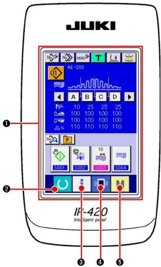
1-1.Name of each section of IP-420....38
1-2. Buttons to be used in common....39
- Basic operation of the sewing machine ....40
- LCD display section at the time of independent sewing....42
3-1.Data input screen 42
3-2.Sewing screen 44
- Selecting a pattern....46
4-1. Selection on the data input screen....46
4-2. Selection by means of the PATTERN DIRECT button....47
-
Naming the pattern....48
-
Sewing data editing function....49
-
Winding a bobbin....51
7-1. Bobbin winding procedure....51
7-2. Adjusting the bobbin thread amount....51
7-3. Adjusting the bobbin winder ....52
- Using counter....53
8-1. Setting procedure of the counter....53
8-2. Count-up releasing procedure 55
8-3. Method for changing the value of the counter during sewing....55
- Using the TEMPORARY STOP button....56
- Changing sewing data....57
- Registering a new sewing pattern....59
- Sewing data list....60
- Copying sewing pattern....69
- Registering the direct pattern....71
14-1. Registration procedure....71
14-2. State of registration at the time of purchase 72
- Registering the sewing data with the CUSTOMIZATION button....73
15-1. Registration procedure....73
15-2. State of registration at the time of purchase 74
-
Changing sewing mode....75
-
On the LCD display for cycle sewing....76
17-1. Data input screen ....76
17-2. Sewing screen ....77
- Performing the cycle sewing....79
18-1. Selection of cycle data....79
18-2. Editing procedure of the cycle sewing....80
18-3. Editing the currently-selected sewing data in cycle data....82
18-4. Method for deleting the cycle data ....83
18-5. Method for deleting a step of the cycle data....84
-
Changing the memory switch data 85
-
List of memory switch data 87
20-1. Level 1 ....87
20-2. Level 2....90
- Setting the upper shirring....91
- Setting the manipulator pressure....92
- Using the teaching....93
23-1. Start teaching....93
23-2. Finish teaching 95
- Using check program....96
24-1. Displaying the check program screen....96
24-2. Adjusting the feed pitch....97
24-3. Correcting the bottom feed amount readout potentiometer 98
24-4. Replacing the main shaft motor belt 99
24-5. Performing sensor check ....100
24-6.Performing LCD check....102
24-7. Performing touch panel compensation....103
-
Error code list ....107
-
Using communication function 111
26-1. Handling possible data 111
26-2. Performing communication by using the media 112
26-3. Carrying out communication with a USB thumb drive 113
26-4. Performing formatting of the media 115
26-5. Take-in of the data....117
- Information function....120
27-1. Observing the maintenance and inspection information .... 121
27-2. Inputting the inspection time ....124
27-3. Releasing procedure of the warning 125
27-4. Observing the production control information....126
27-4-1. When displaying from the information screen ....126
27-4-2. When displaying from the sewing screen....128
27-5. Performing setting of the production control information....129
27-6. Observing the working measurement information 132
- Performing keylock ....136
- Displaying version information....138
- Communication screen of maintenance personnel level 140
30-1. Data which are possible to be handled....140
30-2. Displaying maintenance personnel level....141
- Information screen of the maintenance personnel level 142
31-1. Display of error record....142
31-2. Display of the cumulative working information....144
VII. HANDLING AND ADJUSTING THE PARTS....145
- Adjusting the material slippage and manipulator pressure 145
- Material auxiliary feed air blow....149
2-1. Material blowing air nozzles....149
2-2. Adjusting the air blow-off pressure 149
- Hand switch....149
- Material end sensor....150
- Adjusting the seam allowance....150
- Adjusting height of the upper manipulator roller 151
- Pin tuck device S200 for AE-200A, AE-200AN 152
7-1. Specifications .... 152
7-2. Adhering a scale....152
7-3. Replacing the upper manipulator sensor and cloth guide....153
7-4. Installing the ruler ....155
VIII. ADJUSTING THE SEWING MACHINE....159
- Adjusting the presser foot lifting lever 159
- Thread tension 159
- Thread take-up spring....160
-
Presser foot lifting lever....160
-
Adjusting the presser foot pressure....160
- Adjusting the walking foot pressure....161
- Adjusting the thread take-up amount by thread take-up lever....161
- How to adjust the amount of oil (oil splashes) in the hook 162
- Needle-to-hook relation....164
- Counter knife....165
- Adjusting the feed timing....165
- Inclination of the feed dog 166
- Height of the feed dog....166
- Lateral position of the feed dog 166
- Precautions to be taken when correcting the longitudinal position of the walking foot....167
IX. MAINTENANCE AND INSPECTION....168
- Draining the filter regulator....168
- Cleaning the sensor....168
- Lubricating the manipulator roller section....168
- Replacing the fuse....169
- List of optional parts for AE-200AN 169
- Disposal of batteries ....170
- Setting data recording paper for AE-200AN....172
Following items have to be checked every working day before the operation of the machine and before the start of work hours.
- Ascertain that the oil pan is filled with the predetermined amount of oil.
- Never operate the machine unless the oil pan has been filled up with oil.
- Ascertain that the pressure gauge indicates the designated air pressure of 0.5 MPa.
* (This is necessary particularly when the compressor is stopped for a lunch break or the like.)
If the compressed air pressure is equal to or less than the designated value, troubles such as interference between the parts can occur. It is therefore necessary to carefully check the compressed air pressure.
-
Check whether the needle thread/bobbin thread need to be replenished.
-
To perform sewing immediately after turning ON the power switch, perform trial stitching first, then proceed with sewing of actual products after the test sewing.
-
In order to prevent the sensor from showing a detecting failure, be sure to clean thread waste around the sensor using an air gun once or more times a day.
1. Precautions for use
- For a wider material, fold the material toward you and sew it while putting your hand on it. If you don't guide the fabric by hand during sewing, the material may warp at the end of sewing.
- When sewing some patterns, it is also necessary to put your hand on the material at the end of sewing.
- Setscrew for the presser bar base

text_image
Technical diagram of a mechanical assembly with labeled component '1'1) Never loosen setscrew ① in the presser bar base. If it is loosened, the walking foot movement timing will change from the correct one.
2) When it is really necessary to loosen setscrew ①, it should be loosened when the walking foot comes down to contact the throat plate surface.
II. CONFIGURATION OF THE MACHINE

text_image
Technical diagram of a sewing machine with labeled parts from O to J, showing structural components and wiring connections.A Machine head (DLU-5498N-7)
B Start switch
© Operation panel
Thread stand
E Upper manipulator
F Auxiliary table
G Sewing machine table
Power switch
(also used as the emergency stop switch)
Control box
J T stand
K Bobbin winder
Air blow SC (Speed controller)
M T stand
N SS52 Stacker device (optional)
Safety bar (optional)
Air valve switch
Material end sensor
R 2-pedal unit (optional)
S Bobbin winder (optional)
Air gun
III. OVERVIEW
This automatic machine consists of a bottom & variable top-feed, lockstitch machine with an automatic thread trimmer, auto-lifter, upper and lower manipulators which control the material end with accuracy, control box which controls the whole system, operation panel and auxiliary table.
(The sewing machine head is DLU-5498N-7 specifically developed for AE-200A, AE-200AN.)
Stacker device (SS52), 2-pedal unit, bobbin winder and bobbin thread remaining amount detecting device are provided as options.
1. Features
1) Easy operation requiring no skill (Even an inexperienced operator is able to carry out work equivalent to that by a skilled operator.)
2) Increased efficiency is promised. (Re-arrangement of two pieces of fabric is required during manual work. This machine eliminates such a re-arrangement, thereby shortening the time required for sewing.)
3) High-quality is ensured to improve reliability. (The sewing machine sews the materials with a consistent seam allowance, thereby producing uniform products.)
4) The sewing machine permits the operator to operate it from its side face automatically or manually by means of the pedal either standing or sitting.
5) The 2-pedal unit ensures accurate placement of the material on the sewing machine.
6) Seam allowance can be set in the range of 1 and 30 mm.
7) Uneven material feed can be adjusted with ease.
2. Specifications
| 1 S | speed of stitch 200 to 3,500 sti/min | |
| 2 St | titch length 0 to 4 mm | |
| 3 Top feed amount 8 mm (Max.) | ||
| 4 Presser foot lift (max.) 10 mm (Air-driven) | ||
| 5 Seam allowance 1 to 30 mm | ||
| 6 Needle to be used DBx1 #9 to #18 | (Standard: #11) | |
| 7 | Sewing conditionA) Curve sewingB) Material sizeC) Number of plies of materials | 100 mm R or more1,500 (length) x 500 (width) or less2 or 1 |
| 8 Power consumption 280VA | ||
| 9 Power source | 3-phase 200 to 240 VSingle-phase 200 to 240 V | |
| 10 Table height Adjustable between 820 to 1,020 mm (Standard: 917 mm) | ||
| 11 | Sewing machine dimensions 2,375 (length) x 1,200 (width) x 1,150 (height) (mm)Auxiliary table Standard: 1,200 (length) x 550 (width) mm | |
| 12 Stacker SS52 Workpiece constant-retaining type | ||
| 13 2-pedal unit | Provided with the presser foot up/down switch and 2-step start switch; high/low speed changeover | |
| 14 Weight 135 kg (when all options are installed) | ||
| 15 Noise | - Equivalent continuous emission sound pressure level ( L_pA ) at the workstation:A-weighted value of 80 dB; (Includes K_pA = 2.5 dB); according to ISO 10821-C.6.3 -ISO 11204 GR2, at sewing cycle: 4 s ON and 7 s OFF. | |
IV. INSTALLATION
1. Table height

CAUTION :
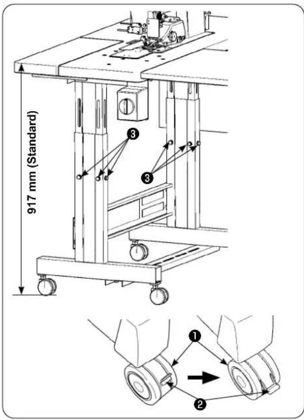
Be sure not to lift the table by one worker but to lift it with four or more workers for supporting each of the four corners of the table when adjusting the table height.
text_image
917 mm (Standard) ① ② ③ ④The table height can be adjusted in the range of 820 and 1,020 mm. The standard height is 917 mm.
1) Install the table stand on a flat place.
2) Casters ① are secured by lowering levers ②.
3) Loosen six bolts ③ mounted on the right and left legs of the table stand to adjust the table height.
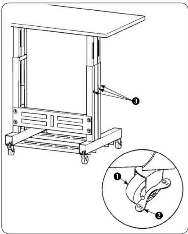
[Table height of the auxiliary table]
text_image
Technical diagram of a mechanical device with labeled parts and an inset showing a close-up of the component.1) Install the table stand on a flat place.
2) Casters ① are secured by lowering the ON side of levers ②.
3) Loosen six bolts ③ mounted on the right and left legs of the table stand to adjust the table height.
2. Auxiliary table

CAUTION :
When installing the auxiliary table, the related parts may drop off or the table may fall causing personal injury. To prevent this, be sure to carry out the installation of the auxiliary table with two workers. One of them has to support the table. When installing the auxiliary table to the sewing machine table, take care not to allow your hands, fingers, etc. to be caught between them.
natural_image
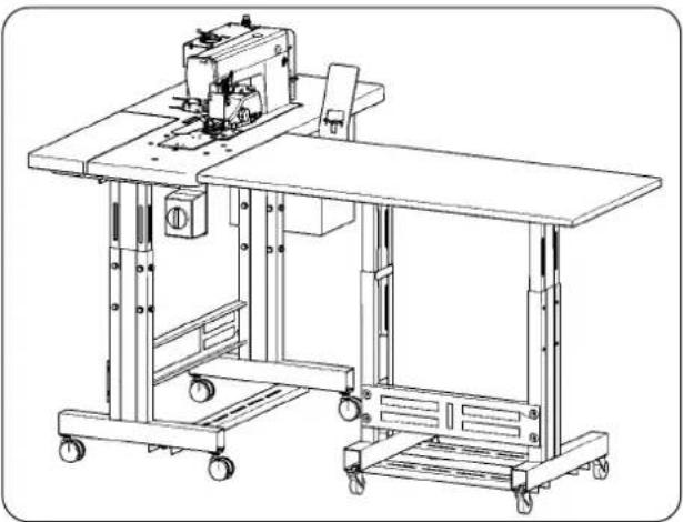
Technical line drawing of a mechanical sewing machine with wheels and a cutting board (no text or symbols)Adjust the auxiliary table height to the sewing machine table height.
3. Assembling the sewing machine table and auxiliary table

CAUTION :
When using tools, take care to prevent parts from dropping resulting in personal injury. Take also care not to get injured with the tool.

text_image
Technical diagram of a mechanical assembly with numbered components for identificationFix spacer ① and auxiliary table joint bracket ④ with three wood screws ② on auxiliary table ③. Then, mount the joint bracket onto table ⑦ with thumb screw ⑤ and washer ⑥.
4. Installing the operation panel mounting plate

CAUTION :
When using tools, take care to prevent parts from dropping resulting in personal injury. Take also care not to get injured with the tool.
text_image
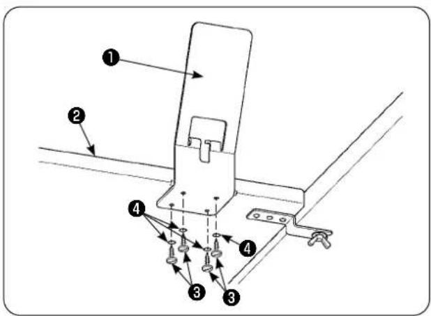
Technical diagram of a mechanical assembly with numbered components and directional arrows indicating assembly steps.Install panel mounting plate ① on auxiliary table ② with four wood screws ③ and four washers ④.
5. Connecting the operation panel

CAUTION :
To avoid possible accident due to abrupt start of the sewing machine, turn off the power to the machine beforehand.

text_image
Technical diagram showing rope routing and hanging components with numbered labels1) Remove cable clip band ② of operation panel cable ① bound to the air hose.
* The cable clip band you have removed will be used in the later procedure.

natural_image
Technical line drawing of a mechanical component with a labeled part (1), showing no text or symbols beyond the label.2) Draw out operation panel cable ① up to the operator side.

text_image
Technical diagram of a cable or cable connector with labeled parts 1, 2, and 33) In the aforementioned state, secure operation panel cable ① you have removed in step 1) to operation panel mounting plate ③ with cable clip band ② as shown in the figure.
flowchart
graph TD
    A["Hairpin Knot"] --> B["Step 1"]
    B --> C["Step 2"]
    C --> D["Step 3"]
    D --> E["Step 4"]
    E --> F["Step 5"]
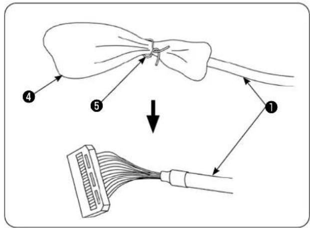
4) Remove bag ④ and plastic band ⑤ that cover the connector of operation panel cable ①.

text_image
JUKI IP-420 IP-420 ① ⑥ ⑦5) Connect connector ⑦ of operation panel cable ① to operation panel ⑥.

text_image
Technical diagram of a device with numbered parts labeled 1, 2, and 6 pointing to different components.6) Bring operation panel cable ① extending between operation panel ⑥ and cable clip band ② under the table.
6. Lubrication

CAUTION :
When tilting or re-raising the sewing machine, take care not to allow your fingers or any other part of your body to be caught.
text_image
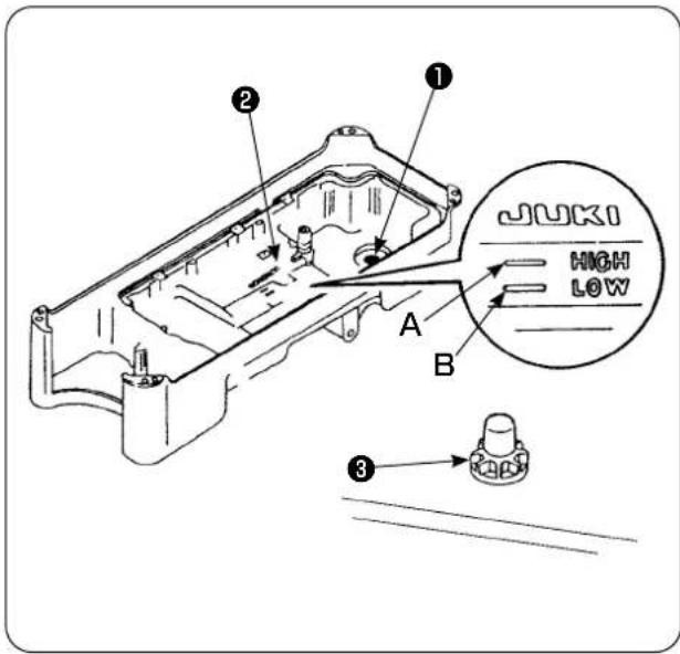
JUKI HIGH LOW A B ① ② ③Before operating the sewing machine
1) Put magnet ① supplied with the unit in the waste oil screw section.
2) Fill oil pan ② with JUKI New Defrix Oil No. 1 until HIGH mark (A) is reached.
3) When the oil level lowers below LOW mark (B), re-fill the oil pan with the specified oil.
4) When you operate the sewing machine after lubrication, you will see splashing of oil through oil sight window ③ if the lubrication is normal.
5) Note that the amount of the splashing oil does not represent the amount of oil in the oil pan.

-
When operating a newly installed sewing machine or a machine which has not been used a long period, be sure to run the sewing machine for approximately 10 minutes for the purpose of break-in using the bobbin winding key mounted on the operation panel.
-
Be sure to use JUKI's genuine oil. If any other oil is used, a trouble may be caused.
7. Installing the thread stand

text_image
Technical diagram of a mechanical assembly with numbered components, likely for assembly or maintenance instructions.1) Assemble the thread stand unit. Then, insert the assembled thread stand into the hole in the table.
2) Tighten locknut ① to fix the thread stand.
3) When ceiling wiring is possible, pass the power cord through spool rest rod ②.

Be sure to install intermediate thread guide ③ to the thread stand without exceptions.
text_image
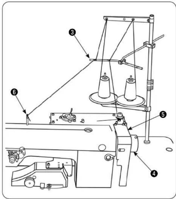
Technical diagram of a sewing machine with numbered components for identification4) Place the thread stand so that its spool holder disks are brought to the rear side of the sewing machine in order to prevent the thread from getting in and caught between handwheel ④ and belt cover ⑤ of the sewing machine. In addition, use intermediate thread guide ③ of the thread stand to minimize the length of thread extending from that guide to thread guide ⑥ of the sewing machine.
Check the following items to make sure that the thread will neither get into nor be entangled in handwheel ④ of the sewing machine.
- Be sure to use intermediate thread guide ③ and pass the thread through it when threading the machine head in order to prevent the thread from getting into handwheel ④.
- The thread drawn from the thread stand may slack and get caught in the handwheel due to the effects of wind (direction). Check the direction, etc. of wind.
- Be aware that, in the case you have tilted the sewing machine for maintenance, the thread drawn from the thread stand may slack and get entangled in handwheel ④ when you raise the sewing machine after the completion of maintenance.
text_image
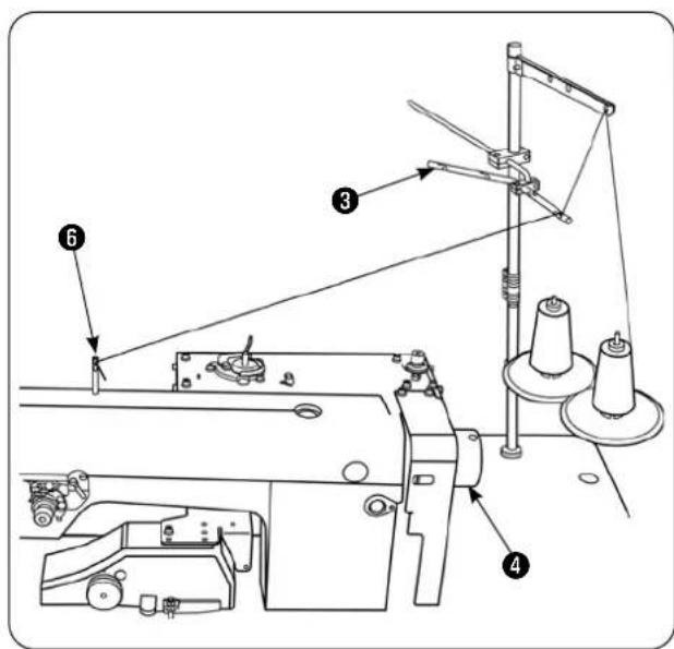
Technical diagram of a sewing machine with numbered components and labeled parts5) As an example of poor installation of the thread stand, if the thread stand is installed so that its spool holder disks are brought to handwheel ④ side, the thread extending from intermediate thread guide ③ of the thread stand to thread guide ⑥ of the sewing machine passes above handwheel ④ during sewing. In this case, the thread is likely to slack and may be entangled in handwheel ④.
8. Removing the covers

natural_image
Technical line drawing of a sewing machine mechanism (no text or symbols)1) Remove upper manipulator roller cover ①.
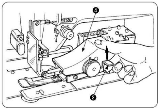
text_image
Technical diagram showing hands operating a mechanical device with numbered parts labeled 1, 2, and 4.2) Putting your finger on lever ②, lift the lever to release the upper manipulator ④.

natural_image
Technical line drawing of a mechanical assembly with no visible text or symbols3) Rotate the upper manipulator to remove lower manipulator roller cover ③.
After the removal of the upper and lower manipulator roller covers, replace the upper manipulator ④ back to its position.

text_image
Technical diagram of a sewing machine with numbered parts and directional arrows indicating assembly steps4) To rotate upper manipulator ④ back to its home position, rotate upper manipulator ④ until it comes in contact with stopper screw ⑤ , then press upper manipulator ④ downward ⑥ .

If you press the upper manipulator downward ⑥ while rotating it, the underside of sensor ⑦ can come in contact with the machine table and the top plate of the bed, resulting a failure.
9. Threading the machine head

CAUTION :
To avoid possible accident due to abrupt start of the sewing machine, turn off the power to the machine beforehand.

text_image
Technical diagram of a sewing machine with numbered parts and close-up insets showing mechanical assembly details.Thread the machine head in the order as illustrated in the figure.
Drive thread guide pin A in the hole on the top surface of the machine arm before threading it.
10. Adjusting the stitch length
text_image
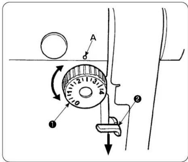
Diagram of a mechanical device with labeled parts and directional arrows indicating motion or movement.Bottom feed length
1) Turn stitch dial ① in the direction of the arrow until a desired numeral is aligned with marker dot (A) on the machine arm.
2) The numerals are given in millimeters (mm).
3) To change the feed length from a larger value to a smaller value, turn stitch dial ① while pressing feed lever ② in the direction of the arrow.
Top feed length
Refer to "VI-24-3. Correcting the bottom feed amount readout potentiometer" p.98 for how to adjust the top feed length.
11. Fitting a needle

CAUTION :
To avoid possible accident due to abrupt start of the sewing machine, turn off the power to the machine beforehand.

text_image
Technical diagram of a mechanical assembly with labeled parts and directional arrows indicating movement or force.Turn off the power to the motor.
Use DBx1 (DPx1 for the DP type sewing machine) needle.
1) Turn the handwheel to move the needle bar up to its highest position.
2) Loosen needle clamping screw ②. Hold needle ① so that its scarf (A) faces exactly to the right (B).
3) Insert the needle fully into the hole in the needle bar in the direction of the arrow until it goes no further.
4) Securely tighten needle clamping screw ②.
5) Check to be sure that slot ( C) in the needle faces just left (D) direction.
12. Loading the bobbin
text_image
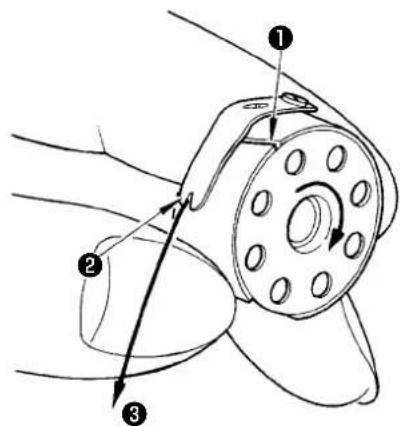
Technical diagram of a mechanical component with numbered parts and directional arrows indicating motion or assembly.1) Holding the bobbin so that thread inside the bobbin spins clockwise, put it in the bobbin case.
2) Pass the thread through slot ① in the bobbin case. Draw the thread in toward thread opening ②, and it will appear from thread opening ② through under the tension spring.
3) Check to be sure that the bobbin rotates in the direction of the arrow when drawing bobbin thread ③.
13. Connecting and adjusting the air source

CAUTION :
To avoid possible accident due to abrupt start of the sewing machine, turn off the power to the machine and make sure that the machine does not run even when you depress the start pedal.
text_image
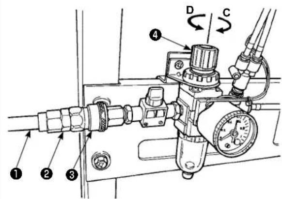
Technical diagram of a pressure regulator with labeled components and directional arrows indicating flow or movement.1) Insert air hose ① into one-touch utility joint ② supplied with the unit.
2) Insert one-touch utility joint ② into joint ③ until it clicks.
3) Adjust the air pressure to 0.5 MPa (5 kgf/cm ^2 ).
If the pressure is inadequate, lift knob ④ and turn it clockwise (in direction C).
If the pressure is too high, turn the knob counterclockwise (in direction D).
When the air presser is set at 0.5 MPa (5 kgf/cm²), lower knob ④ and fix it.
V. INSTALLING THE OPTIONAL DEVICES
1. Installing the 2-pedal unit

CAUTION :
Be sure to turn off the power to the sewing machine before installation of the 2-pedal unit in order to protect the electric parts from being damaged.

text_image
Technical diagram showing a mechanical device with labeled parts and an inset view of its assembly with numbered components.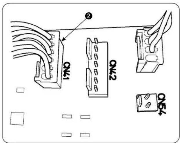
text_image
Q4-1 Q4-2 Q4-31) Pass 2-pedal unit cord ② through the cord through-hole in control box ①.
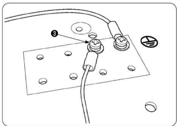
2) Connect the 2-pedal unit cord ② to the CN41 on the main PCB in the electrical control box ①. In addition, connect the ground wire to ground wire setscrew ③ located on the undersurface of the electrical control box ①.
text_image
Technical diagram showing a circuit board with labeled components and numbered parts, including a numbered marker '3' pointing to a component.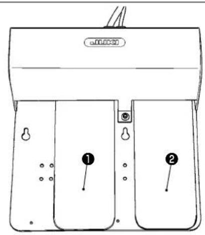
text_image
a000030 ① ②2. Installing the stacker

CAUTION :
Be sure to turn off the power to the sewing machine before installation of the 2-pedal unit in order to protect the electric parts from being damaged.

text_image
Stacker solenoid valve① Left pedal, 2-step pedal (manual start, pause)
1) Place the material on the machine under the manual start mode. The LED at the hand switch section flashes on and off. When you depress the pedal to the first step, the presser foot of the sewing machine comes down. When you depress the pedal to the second step with the presser foot of the sewing machine remained in the lowest position, the sewing machine starts running.
When you depress the pedal to the fist step and release it with the presser foot of the sewing machine remained in the lowest position, the presser foot of the sewing machine goes up.
2) When you depress the pedal during sewing, the sewing machine pauses. When you depress the pedal again, the machine re-starts sewing.
② Right pedal (changeover of speed between high and low)
1) When you depress the pedal during sewing, the speed of stitch changes over from high speed to low speed.
2) When you depress the pedal during pause, the thread trimmer actuates to trim the thread and the sewing machine stops.
text_image
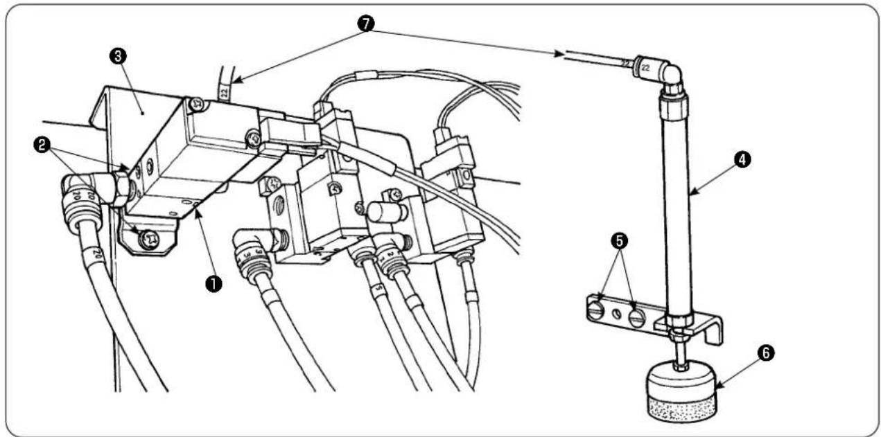
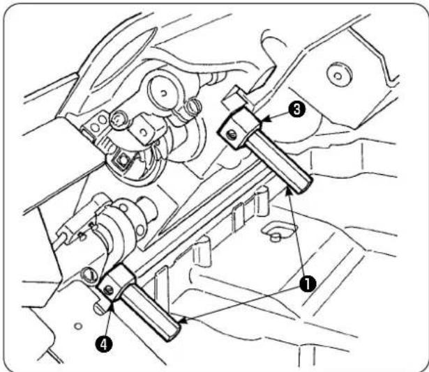
Technical diagram of a mechanical assembly with numbered components and labeled parts1) Install solenoid valve asm. ① on solenoid valve mounting plate ③ with setscrews ②.
2) Place material presser cylinder asm. ④ on the side of the machine head with setscrews ⑤ . At this time, extend top end ⑥ of the cylinder to make sure that the cylinder lightly holds the material.
3) Pass 4 air pipe ⑦ of solenoid valve asm. through the hole in the table and connect to cylinder ④.
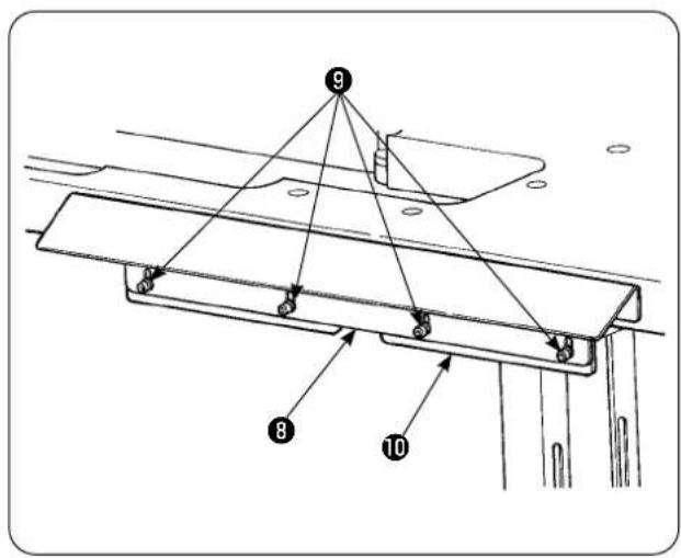
text_image
9 8 104) Place table bracket ⑩ on support plate ⑧ with screws ⑨.
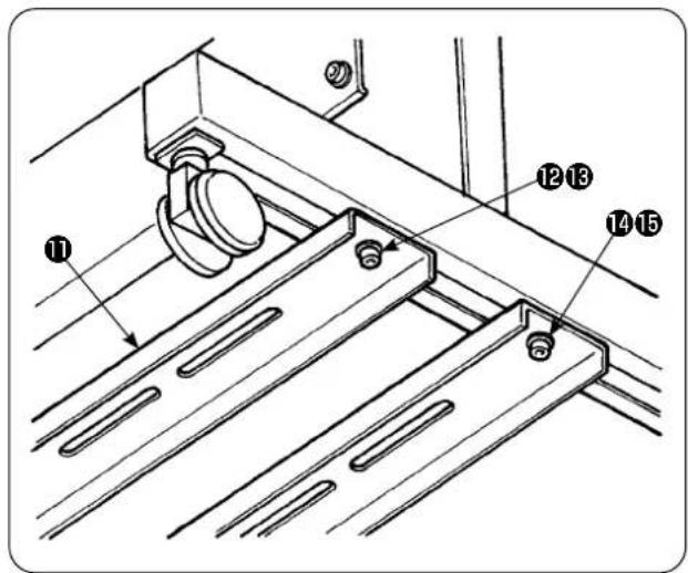
text_image
Technical diagram of a mechanical assembly with numbered components labeled 1, 2, 3, 4, and 5.5) Temporarily place lower support strut ⑪ on the table stand with screw nuts ⑫ and ⑬. Then, loosen screw nuts ⑭ and ⑮.

text_image
16 17 186) Secure the main body of the stacker on lower support strut ⑪ with screw washer nuts ⑯, ⑰ and ⑱.

text_image
8 19 Place inside7) Move the main body of the stacker so that garment body wiper ⑲ is placed inside support plate ⑧. Then, securely tighten ⑫ to ⑮ which have been temporarily tightened in step 5).

text_image
Technical diagram of an electrical component with numbered parts labeled 20 and 218) Branch the air pipe of the air gun. Connect the air pipe to 6 air coupling 21 coming from stacker solenoid valve 20. (See the air piping diagram.)
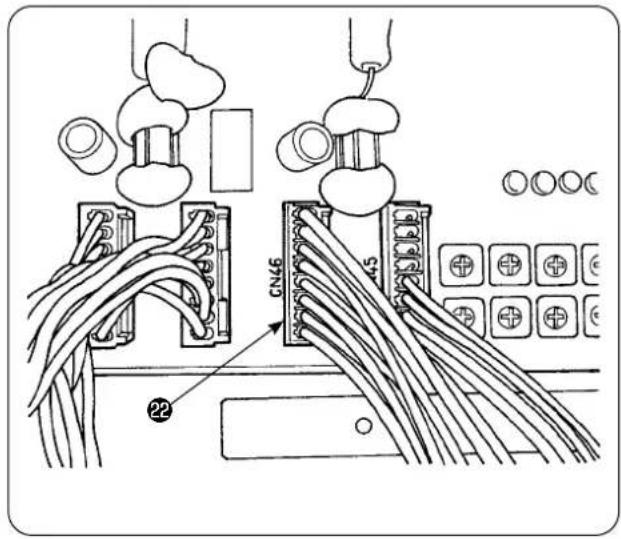
text_image
CN46 229) Connect the cable of stacker solenoid valve 22 to CN46 mounted inside the control box.

text_image
BOX side PCB CN59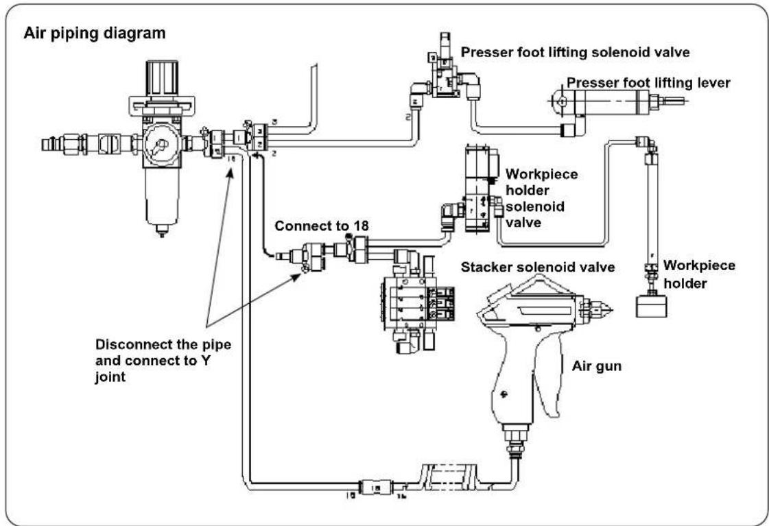
flowchart
graph TD
    A["Air gun"] --> B["Stacker solenoid valve"]
    B --> C["Workpiece holder"]
    C --> D["Presser foot lifting lever"]
    D --> E["Presser foot lifting solenoid valve"]
    E --> F["Connect to 18"]
    F --> G["Connect to 18"]
    G --> H["Disconnect the pipe and connect to Y joint"]
    H --> I["Air piping diagram"]
    style A fill:#f9f,stroke:#333
    style I fill:#ccf,stroke:#333
- Adjusting the workpiece holder

CAUTION :
To avoid possible accident due to abrupt start of the sewing machine, turn off the power to the machine and make sure that the machine does not run even when you depress the start pedal. In addition, take care not to allow your fingers to be caught under the stacker workpiece holder since it comes down.

text_image
JUKI ① ②1) Adjust the pressure of workpiece holder ① to the standard value so that the workpiece holder lightly holds two plies of material and allows them to smoothly come off when the stacker cloth wiper bar actuates. (Clearance (A))
2) To adjust the pressure, loosen workpiece holder locknut ② and turn the workpiece holder counterclockwise to decrease the pressure or clockwise to increase it.

text_image
Clockwise Counterclockwise A B3) Sponge ( B) is a consumable part. When it has worn out, replace it with a new one. (Part number: 18072603)
• Installing the stacker safety bar

CAUTION :
Be sure to securely mount parts and firmly tighten screws and bolts since parts may come off resulting in personal injury.
Install the safety bar on the sewing machine table.
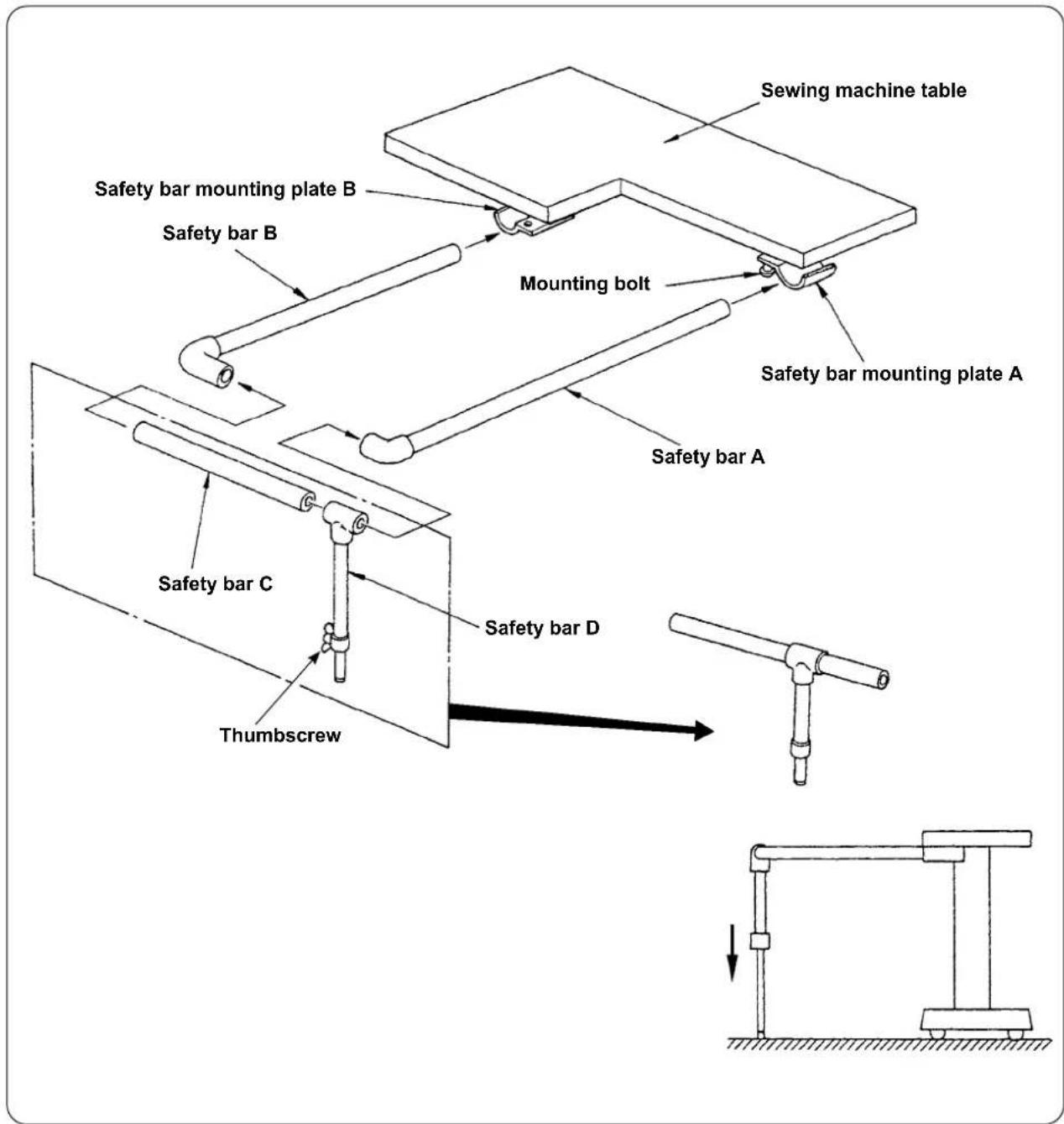
text_image
Sewing machine table Safety bar mounting plate B Safety bar B Mounting bolt Safety bar mounting plate A Safety bar A Safety bar C Thumbscrew Safety bar D1) Loosen safety bar mounting plates A and B to such an extent that safety bars A and B can be inserted.
2) Combine the respective safety bars and insert them respectively into mounting plates A and B, then, secure with mounting bolts.
3) Bring safety bar D down to reach the floor surface and secure with the thumbscrew.
- Adjusting the stacker timing

CAUTION :
To avoid possible accident due to abrupt start of the sewing machine, turn off the power to the machine and make sure that the machine does not run even when you depress the start pedal.
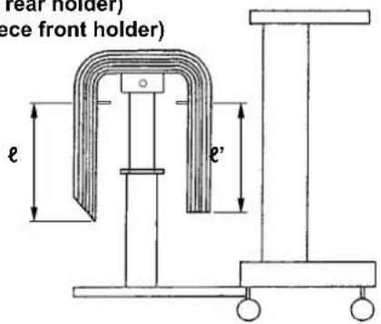
ℓ (Workpiece rear holder)
÷ ' (Workpiece front holder)
text_image
ear holder) ce front holder) e e'1) Adjust the stacker timing so that the workpieces are stacked symmetrically on the cloth receiving table with respect to the longitudinal direction of the workpiece so that the workpieces are stacked with stability.
text_image
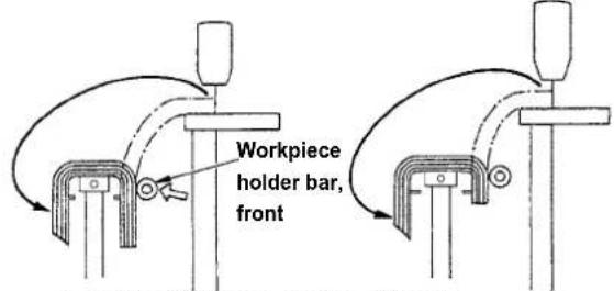
Workpiece holder bar, frontLength: 650mm Length: 500mm
For shorter workpieces length of which is 650 mm or less, adjust the number of stitches on the operation panel so that the workpiece holder bar front actuates simultaneously with the sewing machine finishes sewing.

text_image
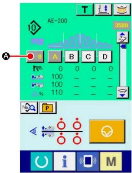
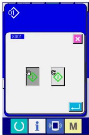
AE-200 A B C D 0 0 0 0 100 100 100 100 100 100 100 100 110 110 110 110 S001 S002 S003 S004 A i MOperation panel setting procedure
① Displaying the data input screen.
Only on the data input screen (blue), the sewing data can be changed. In the case the sewing screen (green) is displayed, press READY key

to display the data input screen (blue).
② Calling up the sewing data screen.
When you press SEWING DATA button

(A), the sewing data screen is displayed.

text_image
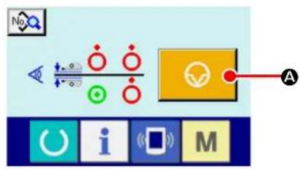
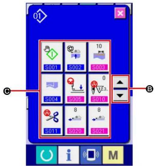
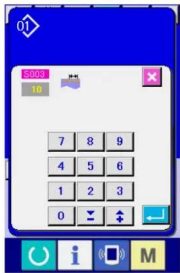
01 100 C S097 0 S088 100 D S089 100 D S090 0 S091 1500 S120 C S130 0 S131 1 S132 B i M③ Selecting the operating position of the stacker.

text_image
When you select STACKER OPERAT- ING POSITION button S131 UP/DOWN SCROLL button S131 change screen is displayed.
text_image
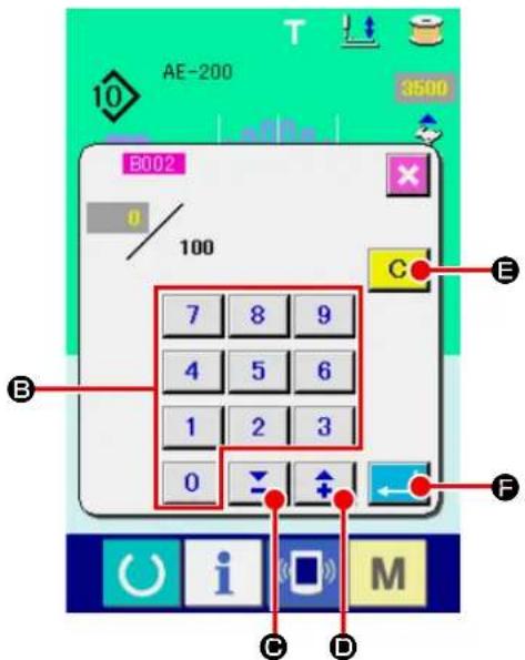
S131 0 7 8 9 4 5 6 1 2 3 0 ↕ ↑ EEnter the number of stitches ( D ) to be sewn before the workpiece holder bar, front operates in accordance with the length of material.
After you have entered the number of stitches, press ENTER button ( ) to save the setting.

text_image
Workpiece holder bar, rear2) To take out the stacked workpieces, change over the air valve switch.
After having taken out the workpieces, return the air valve switch to its previous position.

flowchart
graph TD
    A["Air valve switch"] --> B["Workpiece holder bar"]
    B --> C["To set the workpiece holder bar"]
    style A fill:#f9f,stroke:#333
    style B fill:#ccf,stroke:#333
    style C fill:#cfc,stroke:#333
text_image
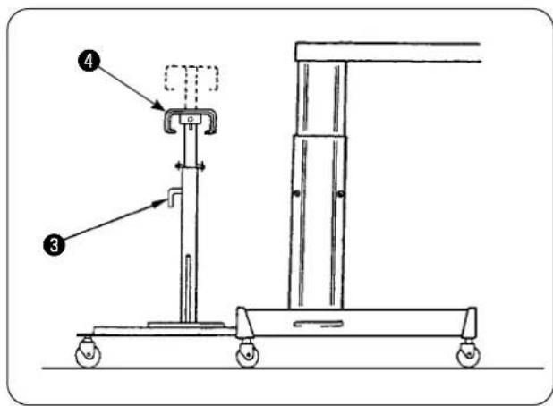
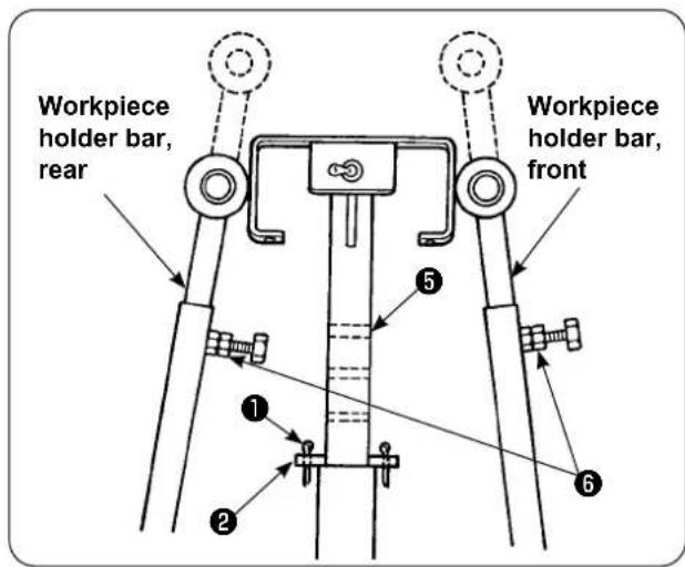
Technical diagram of a mechanical lifting device with labeled parts 3 and 43) To increase the number of workpieces to be stacked on the cloth receiving table, change the position of the table.
① Remove split cotter pin ①, pull out table check pin ②, loosen handle ③ and lower cloth receiving table ④.
② Lower cloth receiving table ④ to a desired height. Insert table check pin into hole ⑤ in the cloth receiving table pipe, insert split cotter pin ① into table lock pin ② , and secure with handle ③ .
③ Loosen bolts ⑥ in the workpiece folder bars, front and rear, and align the bar rubber sections of those bars with the center of cloth receiving table ④, and secure the workpiece holder bars by tightening bolts ⑥.
text_image
Workpiece holder bar, rear Workpiece holder bar, front ① ② ③ ④ ⑤3. Installing and adjusting the bobbin winder

CAUTION :
Securely fix parts by firmly tightening screws with a larger screwdriver and spanner since the parts may come off resulting in personal injury.
3-1. Assembling the bobbin winder
text_image
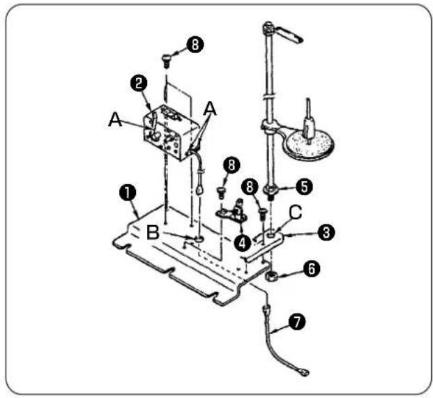
Labeled diagram of a laboratory apparatus with numbered components for identification1) Fix bobbin winder ② on bobbin winder mounting plate ① with two setscrews ⑧. In addition, pass the bundle wires of bobbin winder ② through hole (B) in bobbin winder mounting plate ① and connect them to bobbin winder junction bundle wires ⑦. Insert the other end of ⑦ into CN61 on the main PCB.
2) Place thread stand mounting plate ③ on bobbin winder mounting plate ① with four setscrews ⑧. Mount thread stand asm. ⑤ in hole (C) in ③ and secure with nut ⑥.
3) Install tension regulator ④ on bobbin winder mounting plate ① with two setscrews ⑧.
3-2. Installing and threading the bobbin winder

text_image
550mm 30mm A B C ① ②1) Install the bobbin winder on the auxiliary table with setscrews ① and ② so that the dimensions shown in the sketch at left are obtained.
2) Place thread on spool holder ( B) and pass it through take-up thread guide arm ( A ), then through tension regulator ( C ) and wind on the bobbin.
3) Secure take-up thread guide arm (A) and spool holder (B) so that spool holder (B) does not interfere with thread path when routing the thread from guide asm. (A) to tension regulator (C).
3-3. Winding and adjusting the bobbin

text_image
White engraved marker dot ⑤ ③ F E ① G ⑥ ⑦ D ④ ⑧ ②1) Fit bobbin ① over bobbin winder spindle ②
2) Wind thread on the bobbin by four or five turns in the direction of arrow (D).
3) Bobbin winding starts by pressing bobbin winder stop latch ③ against the bobbin (in the direction of arrow (E)) (breaker ⑤ is in the ON state (where the white engraved marker dot is visible)) and automatically stops when the bobbin has been wound with a predetermined amount of thread (80 to 90 % of the outside diameter of the bobbin).
4) Loosen locknut ④ of the bobbin winder stop latch boss and adjust the amount of thread to be wound on the bobbin by changing the position of bobbin winder stop latch boss ⑧. (When the boss is moved in direction (F), the amount of thread to be wound on the bobbin increases.) (The amount of thread to be wound on the bobbin increases by moving the latch in the direction of arrow (F).)
5) Adjust the thread tension applied by the tension regulator, when winding the bobbin, to 0.4 N to 0.5 N by means of knob ⑦.
6) Loosen screw ⑥ and adjust the position of the tension regulator by moving it in direction (G) (to the right or left) so that thread is wound round the center of bobbin.

-
Even when breaker ⑤ is in the ON state (where the white engraved marker dot is visible), the bobbin winder may fail to operate. In this case, the breaker ⑤ is internally in the OFF state. The bobbin winder should be used after turning OFF and ON the breaker ⑤ in order to avoid such a trouble.
-
Be sure to use JUKI's genuine bobbin and bobbin case.
4. Assembling the thread breakage detecting device and setting of the operation panel

CAUTION :
Securely fix parts by firmly tightening screws with a larger screwdriver and spanner since the parts may come off resulting in personal injury.
text_image
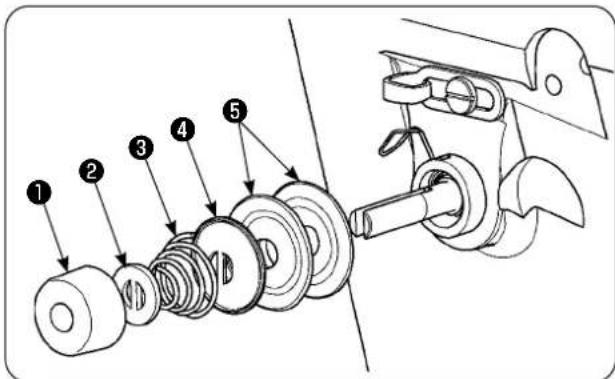
Technical diagram showing exploded view of mechanical components with numbered parts labeled 1 to 51) Loosen tension regulating nut ① of tension regulator asm. No. 2. Remove parts ① to ⑤.

text_image
Technical diagram of a mechanical assembly with numbered components labeled 6, 7, and 82) Place sensor plate mounting plate ⑥ with screws ⑦ and ⑧. Secure the ring crimp contact of the thread breakage detecting plate cable asm. also with screw ⑦.
natural_image
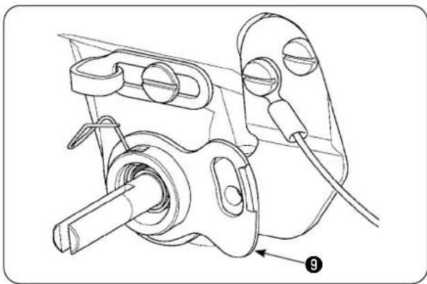
Technical line drawing of a mechanical assembly with no visible text or symbols3) Put thread breakage detecting guide ⑨ over thread tension spring to position as illustrated in the sketch at left.

text_image
Technical diagram of a mechanical assembly with numbered components labeled 10, 11, and 124) Temporarily secure thread breakage detecting plate cable asm. ⑩ and thread breakage detecting plate guide bushing ⑪ with thread breakage detecting plate setscrew ⑫.
text_image
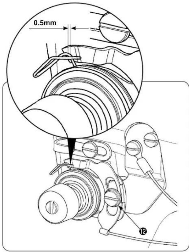
0.5mm 125) Re-assemble parts ① to ⑤ which have been removed in step 1).
6) Turn the thread breakage detecting plate to the position where the pressing amount of the detecting plate against the thread take-up spring is 0.5 mm or less. Then, tighten screw 12.

text_image
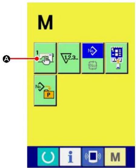
M A 1 R L2.3.. No No POperation panel setting procedure
① Displaying the MEMORY switch list screen.
When you press key, the current screen is
changed over to the mode changeover screen
on which the MEMORY switch button

A)
is displayed. When you press this button, the MEMORY switch data list screen is displayed.

text_image
1 U022 U023 U024 U025 U027 日本語 U500 B C② Selecting the thread breakage detection operation selection.
When you select THREAD BREAKAGE
DETECTION OPERATION SELECT button

(B) by pressing UP/DOWN SCROLL
button (▲▼) and press the former, the thread breakage detection operation selection screen is displayed.

text_image
U023 DSelect the "ENABLE" of the thread breakage detection.
After you have set the status of the thread
breakage detection, press ENTER

D)
button to save the setting.
text_image
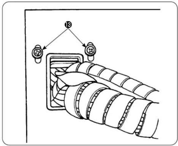
137) Loosen setscrews 13 of the cord keep plate located on the side face of the electrical control box. Lift the cord keep plate and pass the cord of thread breakage detecting plate cable asm. 10 through the hole.
text_image
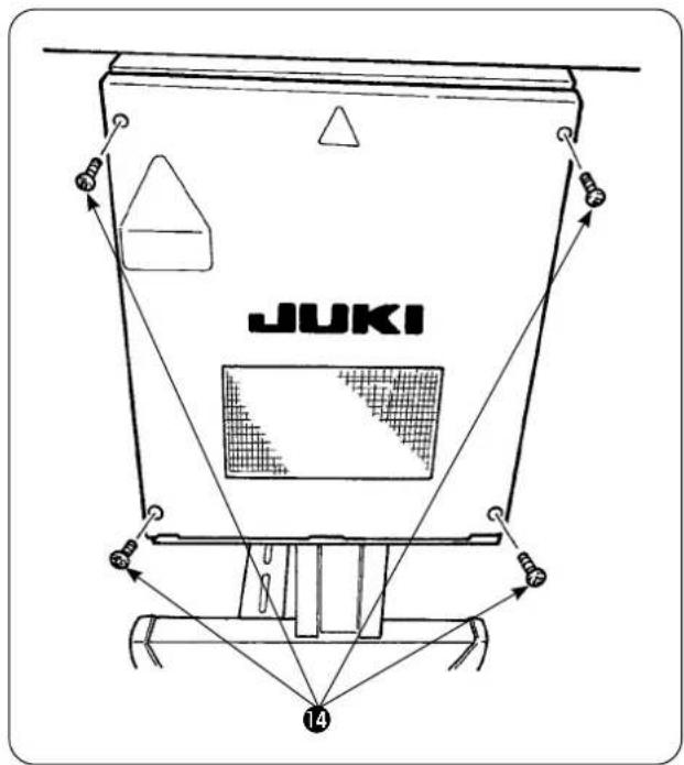
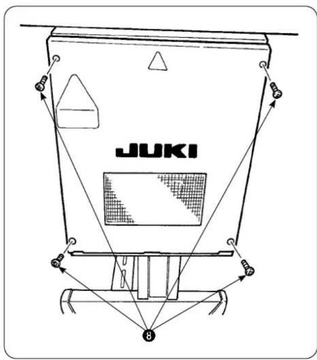
JUKI 14Remove four screws ⑭ which are used to secure the electrical box cover. Open the cover.
8) Insert the connector of thread breakage detecting plate cable asm. 10 into CN60 (3P, yellow) on the main PCB inside the control box.
9) Secure the electrical box cover, lower the cord keep plate and secure the cover with the screws.
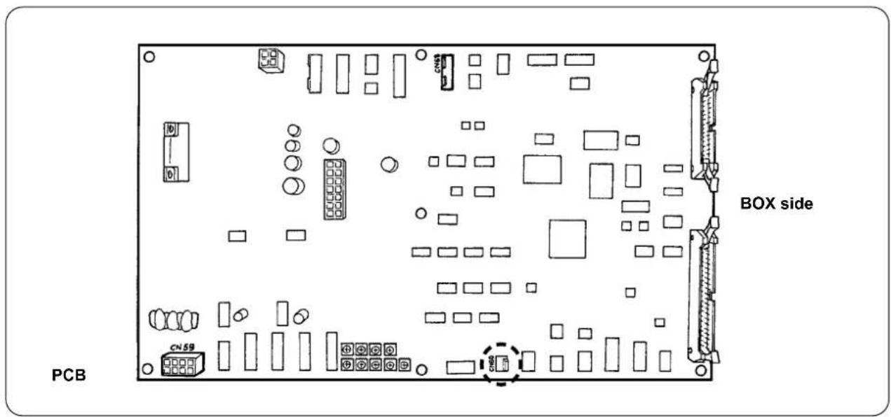
text_image
PCB BOX side CN595. Installing the bobbin thread remaining amount detecting device
5-1. Setting the bobbin thread remaining amount detection
text_image
M 1 A 1.2.3.. No No No P① Displaying the MEMORY switch list screen.
When you press key, the current screen is changed over to the mode changeover screen
on which the MEMORY switch button

A)
is displayed. When you press this button, the MEMORY switch data list screen is displayed.

text_image
800 2000 U016 U017 3000 4000 U018 3500 5000 U019 1 1.2 U020 U021 C B i M② Setting with/without the bobbin thread remaining amount detection.
Select WITHOUT OF BOBBIN THREAD REMAINING AMOUNT DETECTION

(B) by pressing UP/DOWN
SCROLL button


screen is displayed.

text_image
U021 OK ← ←On the with/21 out bobbin thread re- maining amount detection selection screen, set the bobbin thread remaining amount detection to "WITH"
text_image
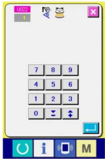
U022 1 7 8 9 4 5 6 1 2 3 0 ↓ ↑③ Setting the number of times of detection of the remaining amount of bobbin thread.
When you select NUMBER OF TIMES OF BOBBIN THREAD REMAINING AMOUNT
DETECTION button by pressing UP/
DOWN SCROLL button (▲▼) on the
MEMORY switch data list screen, num-
ber of times of bobbin thread remaining amount detection setting screen is displayed.
The value you set in this step determines the number of times of bobbin thread remaining amount detection at which the bobbin thread runout warning message is displayed on the sewing machine (to prevent the sewing machine from proceeding to the next sewing). If the amount of bobbin thread remaining on the bobbin is still sufficient for continuing sewing when the bobbin thread runout warning message is displayed on the sewing machine, adjust by increasing the number of times of bobbin thread remaining amount detection. The setting range is 0 (zero) to 19.
If the number of times of bobbin thread remaining amount detection is set to 0 (zero), the bobbin thread remaining amount detection will be temporarily placed in the OFF state. If the bobbin thread remaining amount detecting function does not work, firstly check the set value of this data item.
5-2. Adjusting procedure of the sensor position
Two sensors are used in the bobbin thread remaining amount detecting device. The device does not work properly unless those sensors are correctly positioned.

text_image
Technical diagram of a mechanical assembly with numbered components and directional arrows indicating movement or assembly.1. Home position sensor ①
The one of the two sensors, which is located at the lower side of the device is the home position sensor ①. Check to be sure that the light of the sensor goes out when the detecting rod hides in the hook and lights up when it comes back.
2. Detecting sensor ②
Detecting sensor ②, which is located at the upper side of the device, detects the remaining amount of bobbin thread. The remaining length of thread is changed by moving up or down the mounting position of the sensor. Be sure to adjust the position of the sensor according to the type of bobbin thread to be used and sewing length specified for the process.
1) Uniformly wind the bobbin thread to be actually used for sewing on the bobbin.
The winding length of the thread is roughly as described below.
Example) When the sewing length is 0.5 m:
| 0.5 m | × | 5 | + | 1.5 m | = | 4m |
| (Length of thread for each detection) | (Number of times of detection) | (Bobbin thread remaining length at the time of detection) | ||||
2) Fit the bobbin in the bobbin case (exclusive). Put the bobbin case in the hook.
3) Slightly loosen two detecting sensor fixing screws ③.
4) Turn eccentric pin ⑤ to lower detecting sensor ② little by little from its highest position, while pressing down solenoid arm ④ with one hand.
5) Lower detecting sensor ② until its monitor lamp lights up.
6) Carefully moving the solenoid arm up and down, check to be sure that the monitor lamp of detecting sensor ② flashes on and off.
7) The position at which the monitor lamp lights up and the position at which it goes out are not the same. It is therefore necessary to check the above at the former position.
8) Once the correct position of the sensor is found, securely tighten detecting sensor fixing screw ③. At this time, carefully tighten the screw while preventing the sensor from being displaced.
5-3. Installing the bobbin thread remaining amount detecting devices

Be sure to install the driving device which has already been adjusted. If not, the sewing machine can fail.
text_image
Technical diagram of a mechanical assembly with numbered components and directional arrows indicating assembly or connection.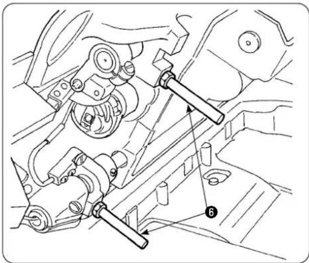
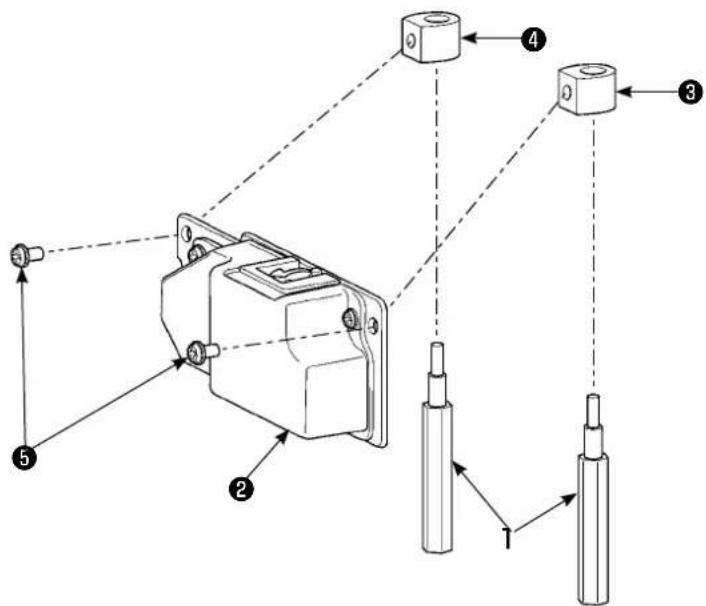
natural_image
Technical line drawing of mechanical components and assembly (no text or symbols)1) Remove two front bed struts ⑥ from the sewing machine to which the bobbin thread remaining amount detecting device is to be installed.
text_image
Technical diagram showing mechanical assembly with numbered components, likely for vehicle maintenance or repair instructions.2) Install base plate stator ③, ④ to the bed with placed between bed struts ① supplied with the unit.
There are two types of base plate stators ③ and ④, one for the left side and the other for the right side. Be sure to install them correctly.
| Base plate stator for the left side (far side) | Area of flat section Small | 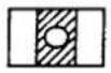 |
| Base plate stator for the right side (Operator side) | Area of flat section Large |  |
text_image
Technical diagram of a mechanical assembly with numbered components, likely illustrating a valve or clamp mechanism.3) Secure driving device ② on right and left base plate stators ③ and ④ with screws ⑤ supplied with the unit. At this time, carefully secure driving device ② so that the detecting rod correctly faces the center of inside of the hook.

text_image
Diagram showing a mechanical assembly with labeled components, including a numbered arrow pointing to component 7.4) Loosen setscrews ⑦ of the cord keep plate located on the side face of the electrical control box. Lift the cord keep plate and pass the sole-noid cord and sensor cord through the hole.
text_image
JUKI 8Remove four screws ⑧ which are used to secure the electrical box cover. Open the cover.
PCB

text_image
BOX side CN59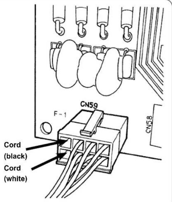
text_image
CN59 F-1 CN58 Cord (black) Cord (white)5) Insert the pins coming out from the solenoid into vacant receptacles of CN59 on the board. Insert the black pin into No. 8 and the white pin into No. 4.
Insert the sensor connector into CN68.
6) Close the electrical box cover. Clamp the cords coming out from the electrical box with the cord keep plate. Now, the installation of the bobbin thread remaining amount detecting sensor. Do not forget to tighten the screws in the cover.
7) Turn ON the power to the sewing machine. Set the bobbin thread remaining amount detection. (Refer to "V-5-5-1. Setting the bobbin thread remaining amount detection" p.30 for the setting procedure.)
About errors
- If the error display [E998] appears on the operation panel, turn OFF the power to the sewing machine once and check that the connectors are fully inserted into the board.
- Remove the cover from the driving device for cleaning. In particular, the sensor and driving section should be carefully cleaned.
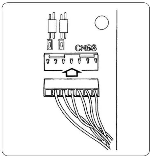
text_image
CN685-4. Sewing

text_image
U022 1 7 8 9 4 5 6 1 2 3 0 ↓ ↑① U022 Set the number of times of detection of the remaining amount of bobbin thread to "1". Refer to "V-5-5-1- ③ Setting the number of times of detection of the remaining amount of bobbin thread." p.31 for the method for setting the number of times of detection of the remaining amount of bobbin thread.
text_image
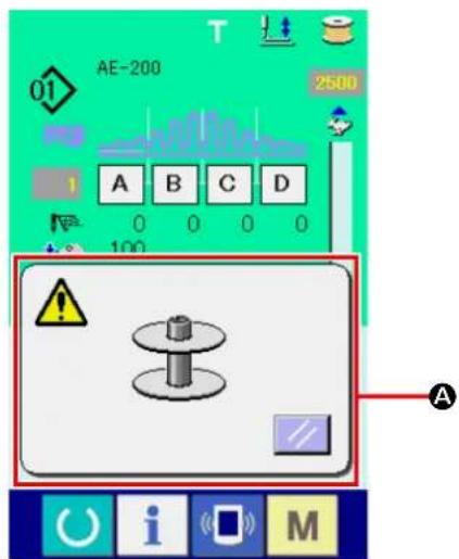
01 AE-200 2500 A B C D 0 0 0 0 100 A ! i M② Start the normal sewing. (For test sewing, specify the sewing length which is same as that for actual process.)
③ If you continue sewing and carry out thread trimming in repetition, the error popup screen (A) will be displayed and the buzzer will sound when the remaining amount of bobbin thread is detected.
④ At this time, observe the actual length of bobbin thread remaining on the bobbin and adjust the counter value appropriately.
⑤ The remaining length of bobbin thread when its runout has been detected by the sensor varies more or less even under the most favorable conditions. This variation is caused by the type of thread or sewing length. As a guide, the remaining length of bobbin thread varies by approximately three turns of thread around the bobbin.
At this time, the length of thread is as shown in the following example.
Adjust the counter so that bobbin thread remains by "a half of variation in length + 0.5 m."
[Example of thread length equivalent to three-turns of thread on the bobbin.]
 | Spun thread #60, #80 | Approximately 2.5 m for three turns around the bobbin |
| Tetoron thread #60, #80 | Approximately 3 m for three turns around the bobbin | |
| Spun thread, Tetoron thread #30 | Approximately 2 m for three turns around the bobbin |
⑥ If the counter value is increased by one, the remaining length of bobbin thread will be shortened by one sewing length.
⑦ Due to the aforementioned variation in the remaining length of bobbin thread, the bobbin thread may completely run out during sewing depending on the adjustment of the counter value. Adjust the counter to the set value which ensures that the bobbin thread will never run out during sewing in accordance with sewing conditions for each sewing process.
⑧ If the bobbin thread runs out during sewing even when the bobbin thread remaining amount adjustment counter at "1," or, to the contrary, if the remaining length of bobbin thread is still too long even when it is set at "19," the position of the detecting sensor has to be adjusted. (Refer to "V-5-5-2. Adjusting procedure of the sensor position" p.32 for the adjusting procedure.)
In the case the bobbin thread runs out → Lower the position of the detecting sensor.
In the case the remaining length of bobbin thread is too long → Raise the position of the detecting sensor.
5-5. For proper operation of the bobbin thread remaining amount detecting device
This device mechanically detects the remaining amount of bobbin thread. Since the device performs detection after thread trimming, the remaining amount of bobbin thread varies by a certain degree. The variation in the remaining amount of bobbin thread can be minimized by paying attention to the following.
1. How the bobbin is wound with thread
The bobbin thread remaining amount detecting device detects the thread amount by directly touching the thread wound on the bobbin with its detecting rod. It is therefore important that the bobbin is uniformly wound with thread. In particular, carefully check how the thread is wound on the bobbin at the beginning of winding.


2. Sewing length
Since the device performs detection after thread trimming, the degree of variation in the remaining amount of bobbin thread differs according to the sewing length of one sewing operation.
In general, the shorter the sewing length of one sewing operation is set, the smaller the variation in the remaining amount of bobbin thread becomes small. In the case multiple processes are combined for sewing where the sewing length differs by process, the variation can become larger.

ength of thread when wound on the bobbin by three turns
| Spun thread #60, #80 Approx. 2 to | 2.5 m |
| Tetoron thread #60, #80 Approx. 3 | m |
| Spun thread, Tetoron thread #30 | Approx. 2 m |
VI. OPERATION SECTION (WITH REGARD TO THE PANEL)
1. Explanation about switches on the operation panel
1-1.Name of each section of IP-420
(Front)
text_image
JUKI AE-200 10 25 25 25 100 100 100 100 100 100 100 100 110 110 110 110 S001 S002 S003 S004 IF-420 Intelligent panel(Right side)
text_image
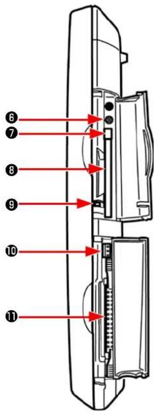
Diagram of a device rear panel with numbered red arrows pointing to internal components6 Brightness control
⑦ CompactFlash (TM) eject button
8 CompactFlash (TM) slot
9 Cover detection switch
10 Connector for external switch
⑪ Connector for control-box connection
Changeover of the data input screen and the sewing screen can be performed.
Changeover of the data input screen and the information screen can be performed.
Changeover of the data input screen and the communication screen can be performed.
Changeover of the data input screen and the mode changeover screen which performs various detail settings can be performed.
1-2. Buttons to be used in common
The buttons which perform common operations in each screen of IP-420 are as follows :

CANCEL button → This button closes the pop-up screen. In case of the data change screen, the data being changed can be cancelled.

ENTER button → This button determines the changed data.

UP SCROLL button → This button scrolls the button or the display in the upward direction.

DOWN SCROLL button → This button scrolls the button or the display in the downward direction.

RESET button → This button performs the release of error.

NUMERAL INPUT button → This button displays ten keys and input of numerals can be performed.

SEWING DATA DISPLAY button → To be used to display the sewing data list corresponding to the currently-selected sewing pattern No.

CHARACTER INPUT button → This button displays the character input screen.

PRESSER FOOT LOWERING button→ Presser is lowered, and the presser lowering screen is displayed. To lift presser, press presser lift button displayed in the presser lowering screen.

BOBBIN WINDING button → Bobbin thread winding is performed.
2. Basic operation of the sewing machine

text_image
U500 Language changeover 日本語 English 中文简体字 Español Tiếng Việt ▲ ▼ i M
text_image
AE-200 10 25 25 25 100 100 100 100 100 100 100 100 110 110 110 110 S001 S002 S003 S004 i M① Turn ON the power switch.
When you turn ON the power to the sewing machine for the first time after purchase, the language selection screen is displayed. Set the language to the one you want to use. (The language setting can be changed with the MEMORY switch "U500".)
* If you exit from the language selection screen with CANCEL button or ENTER button without selecting the language, the language selection screen will be displayed every time you turn ON the power to the sewing machine until you select the language you want to use.
② Select the pattern No. you want to sew.
When you turn ON the power to the sewing machine, the data input screen is displayed. Currently-selected PATTERN No. button (1) (B) is displayed on the upper part of the screen. You can select a pattern No. by pressing that button. Refer to "VI-4. Selecting a pattern" p.46 for the method for selecting a pattern No.
In the purchased state, pattern Nos. 1 to 3 as described in "VI-10. Changing sewing data" p.57 have been factory-registered. Select one from those three pattern numbers. (The number to which no pattern has been registered will not be displayed.)
* Refer to "VI-3-1.Data input screen" p.42 for detailed explanation of this screen.

text_image
Mobile device interface screenshot showing a hand cursor clicking a button with icons for function keys and a stop symbol.
text_image
AE-200 01 3500 0 A B C D 0 0 0 0 100 - 100 - 110 - - - - No i M
text_image
Technical diagram of a mechanical assembly with numbered components, likely for assembly or maintenance instructions.③ Bring the sewing machine into the sewing ready state.
When you press READY key ( Ⓤ), the
power OFF prohibition screen is displayed. The sewing machine prepares for sewing while this screen is displayed. Once the sewing machine is ready for sewing, the background color of the LCD changes to green and the presser foot of the sewing machine goes up.
④ Start sewing.
When you set a sewn product under the presser foot, LED ① blinks. When you press START button ② , the sewing machine starts sewing.
* The pedal switch can be optionally selected for starting sewing instead of the START button.
* Refer to "VI-3-2.Sewing screen" p.44 for detailed explanation of this screen.
Because of the characteristics of the manipulator sensor, the sensor's detection status will be unstable if you turn ON the power to the sewing machine with a material placed on the sewing machine. To prevent the sensor from becoming unstable, carry out placement of the material as described below.

-
Be sure to press the READY key for the first time after turning ON the power to the sewing machine with no material placed on the sensor.
-
If LED ① blinks at a high speed or irregularly, remove the material from the sensor once. Then, re-place the material on the sensor to use the sewing machine.
3. LCD display section at the time of independent sewing
3-1.Data input screen

text_image
A B C D E F No No OOC T F AE-200 G O H N I A B C D 10 25 25 25 100 100 100 100 100 100 100 100 110 110 110 110 K P M L S001 S002 S003 S004| Button and display Description | ||
| A | NEW PATTERN REGISTRATION button | To be used to display the new pattern No. registration screen.→ Refer to "VI-11. Registering a new sewing pattern" p.59. |
| B | PATTERN COPY button To be used to display the pattern copy (copy source selection) screen.→ Refer to "VI-13. Copying sewing pattern" p.69. | |
| C | PATTERN NAME SETTING button | To be used to display the sewing pattern name input screen.→ Refer to "VI-5. Naming the pattern" p.48. |
| D | TEACHING button To be use to display the teaching screen.→ Refer to "VI-23. Using the teaching" p.93. | |
| E | PRESSER FOOT LOWERING button | To be used to display the presser foot lowering screen.If you want to lift the presser foot, press the PRESSER FOOT LIFTING button displayed on the presser foot lowering screen. |
| F | BOBBIN WINDING button To be used to display the bobbin winding screen.Thread can be wound on a bobbin.→ Refer to "VI-7. Winding a bobbin" p.51. | |
| G | PATTERN SELECT button | To be used to display the currently-selected pattern No. on the button. If you press this button, the pattern No. change screen will be displayed.→ Refer to "VI-4. Selecting a pattern" p.46. |
| H | "S04" "Number of plies of material to be sewn" mode display | To be used to display the currently-set "number of plies of material to be sewn" mode |
| I | RIGHT/LEFT SCROLL buttons | When these buttons are pressed, the section display is changed over in sequence. |
| J | Sewing data display To be used to | display the content of the currently-selected pattern data.The displays from top to bottom are:Number of stitches for sectionUpper manipulator pressureLower manipulator pressureUpper shirring amount |
| K | SEWING DATA EDIT button To be | used to display the sewing data list screen.→ Refer to "VI-10. Changing sewing data" p.57. |
| L | CUSTOMIZE buttons | It is possible to assign the sewing data you use frequently to these four buttons. When you press one of these four buttons, the sewing data change screen for the sewing data assigned to that button is displayed.→ Refer to "VI-15. Registering the sewing data with the CUSTOMIZATION button" p.73. |
| M | PATTERN DIRECT button | To be used to display the pattern No. list screen that shows the pattern No. that are registered with the PATTERN DIRECT button.→ Refer to "VI-14. Registering the direct pattern" p.71. |
| N | SEWING DATA SECTION EDIT button | To be used to display the sewing data section editing screen.→ Refer to "VI-6. Sewing data editing function" p.49. |
| O | Patten name display | The name entered in the currently-selected sewing pattern is displayed in this field. |
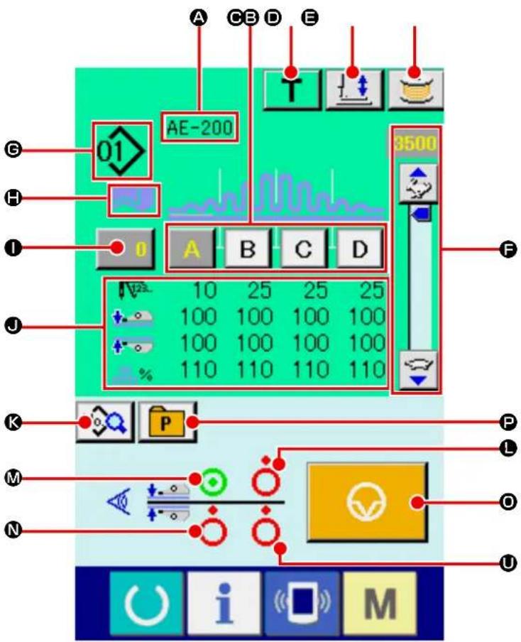
3-2.Sewing screen
text_image
A C B D E 01 AE-200 3500 10 25 25 25 100 100 100 100 100 100 100 100 110 110 110 110 K P L M O N U | The state where the sensor detects a material |
 | The state where the sensor does not detect a material |
 | Currently-sewn section status |
| Button and display Description | ||
| A | Patten name display | The name entered in the currently-selected sewing pattern is displayed in this field. |
| B | SEWING DATA SECTION EDIT button | To be used to display the sewing data section editing screen. |
| C | TEACHING button To be use to display the teaching screen. | |
| D | PRESSER FOOT LOWERING button | To be used to display the presser foot lowering screen.If you want to lift the presser foot, press the PRESSER FOOT LIFTING button displayed on the presser foot lowering screen.* Sewing is completed by pressing this button while the sewing machine is at rest during sewing. |
| E | BOBBIN WINDING button To be used to display the bobbin winding screen.Thread can be wound on a bobbin. | |
| F | SPEED VARIABLE RESISTOR The number of revolutions of the sewing machine can be changed with this variable resistor. | |
| G | PATTERN No. display To be used to display the currently-sewn pattern No.. | |
| H | "S04" "Number of plies of material to be sewn" mode display | To be used to display the currently-set "number of plies of material to be sewn" mode |
| 1 | COUNTER VALUE CHANGE button | The current counter value is displayed on this button. When you press this button, the counter value change screen is displayed. |
| 2 | Sewing data display The currently-sewn pattern data is displayed in this field.• Number of stitches for section• Pressure values of the upper and lower manipulators• Upper shirring amount | |
| 3 | SEWING DATA EDIT button To be used to display the sewing data list screen. | |
| 4 | Presence/absence of material detection status of the upper manipulator outer sensor | State of the sensor is displayed. |
| 5 | Presence/absence of material detection status of the lower manipulator outer sensor | State of the sensor is displayed. |
| 6 | Presence/absence of material detection status of the upper manipulator inner sensor | State of the sensor is displayed. |
| 7 | TEMPORARY STOP button To be used to display the temporary stop screen. | |
| 8 | PATTERN DIRECT button | To be used to display the pattern No. list screen that shows the pattern No.s that are registered with the PATTERN DIRECT button. |
| 9 | Presence/absence of material detection status of the lower manipulator inner sensor | State of the sensor is displayed. |
4. Selecting a pattern
4-1. Selection on the data input screen

text_image
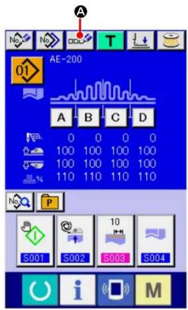
AE-200 A B C D 0 0 0 0 100 100 100 100 100 100 100 100 110 110 110 110 S001 S002 S003 S004 M No P① Display the data input screen.
The pattern No. can be selected only on the data input screen (blue). In the case the sewing screen (green) is displayed, press READY key

to display the data input screen (blue).
② Calling up the pattern No. selection screen.
When you press PATTERN No. SELECT button

(A), the pattern No. selection screen is
displayed. Currently-selected pattern No. and its content are displayed on the upper part of the screen. The list of the registered PATTERN No. buttons is displayed on the lower part of the screen.
text_image
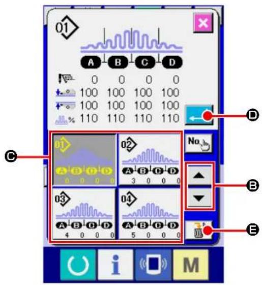
01 A B C D 0 0 0 0 100 100 100 100 100 100 100 100 110 110 110 110 D C 02 No. B 03 04 4 0 0 0 5 0 0 0 E O U i M③ Select a pattern.
When you press UP or DOWN SCROLL button

▼ (B), the registered PATTERN No.
button (☐) is changed over in sequence. Content of the sewing data entered to the pattern No. is displayed on the button. In this state, press the PATTERN No. button (☐) you want to select.
④ Determine the pattern No.
When you press ENTER button (←→), the pattern No. selection screen is closed to terminate the pattern No. selection procedure.
* If you want to delete a registered pattern, press DELETE button ( ) . It should be noted, however, the patterns that are registered with continuous sewing or cycle sewing cannot be deleted.
4-2. Selection by means of the PATTERN DIRECT button
It is possible to register a desired pattern No. with the DIRECT button.
Once you have registered the pattern with the DIRECT button, you can select the pattern with ease only by pressing the DIRECT button.
→ Refer to "VI-14. Registering the direct pattern" p.71.
text_image
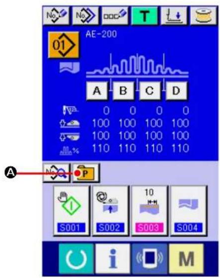
No. No. OOC T AE-200 01 A B C D 0 0 0 0 100 100 100 100 100 100 100 100 110 110 110 110 A S001 S002 S003 S004 i M① Displaying the DIRECT button selection screen.
Press PATTERN DIRECT button (P) on the data input screen (blue) to display the PATTERN DIRECT button selection screen.
* If you have selected "Display" of the DIRECT button with the MEMORY switch (level 2) "Display/non-display of the DIRECT button", you can use the DIRECT button even on the sewing screen.
→ Refer to "VI-14. Registering the direct pattern" p.71.
text_image
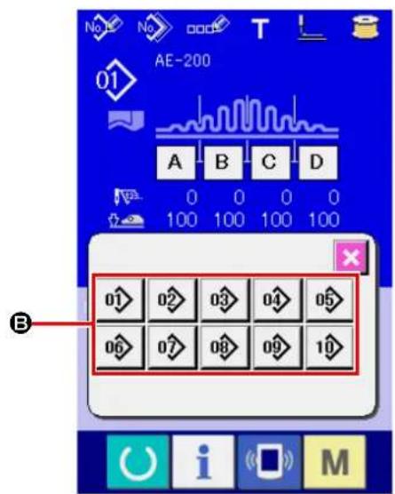
AE-200 01 A B C D 0 0 0 0 100 100 100 100 B 01 02 03 04 05 06 07 08 09 10② Select the pattern No.
It is possible to select the pattern No. registered with the DIRECT button. When you press the PATTERN No. button (B) you want to select, the DIRECT button selection screen is closed and the pattern No. you have selected is displayed.
5. Naming the pattern
As many as 14 characters can be entered to each pattern.
text_image
AE-200 A B C D 0 0 0 0 100 100 100 100 100 100 100 100 110 110 110 110 S001 S002 S003 S004 i M① Display the data input screen.
The pattern No. can be selected only on the data input screen (blue). In the case the sewing screen (green) is displayed, press READY key

to display the data input screen (blue).

text_image
01 AE-200 A B C D E F G H I J K L M N O P Q R S T U V W X Y Z . 1 2 3 4 5 6 7 8 9 0 + - / # B C D E② Calling up the character input screen.
When you press CHARACTER INPUT button

(A), the character input screen is dis-
played.
1) Input the character.
Characters can be entered by pressing the CHARACTER button (B) corresponding to the character you want to input. Characters (A to Z, 0 to 9) and symbols (+, -, /, #, etc.) can be input. As many as 14 characters can be input. The cursor can be moved with CURSOR LEFT
MOVE button

©) or CURSOR RIGHT
MOVE button

(D). If you want to delete
the character you have entered, bring the cursor to the target character and press DELETE
button

E).
2) Finish inputting the character.
When you press ENTER button (←→F), the character input procedure is terminated. After you have exited from the character input screen, the characters you have input are displayed on the upper part of the data input screen.
6. Sewing data editing function

text_image
AE-200 A B C D 0 0 0 0 100 100 100 100 100 100 100 100 110 110 110 110 S001 S002 S003 S004 M① Displaying the sewing data section editing screen.
When you press the SEWING DATA SECTION EDIT button (A) on the individual sewing editing screen (blue), the sewing data section editing screen is displayed.

text_image
01 A S082 0 S080 100 S081 100 S040 110 S041 3500 S042 0 B C D E② Using the sewing data section editing screen.
The target editing section can be changed by pressing RIGHT or LEFT SCROLL button (B).
It is possible to change the sewing data value for each editing unit using -/+ button (●). When you press ENTER button (☐), the setting you have made is confirmed and the screen returns to the individual sewing editing screen.
When you press the SEWING DATA EDIT button (E), the sewing data input screen is displayed.
text_image
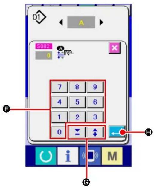
01 S082 7 8 9 4 5 6 1 2 3 0 H i M G③ Using the sewing data input screen.
If you want to change the value you have input, change it with the numeric keypad (F) or -/+ button 📋 ↑ (G).
When you press ENTER button (←→), the sewing data is confirmed and the screen returns to the sewing data section editing screen.
7. Winding a bobbin
7-1. Bobbin winding procedure

text_image
Technical diagram showing mechanical assembly steps with labeled components and directional arrows
text_image
No No DOC T AE-200 01 A T AE-200 3500
text_image
Diagram showing a clock, hourglass, and spool with a blue circular motion indicator, alongside a toolbar with icons for function keys and a labeled point B.① Set a bobbin.
Fit a bobbin over the bobbin winder spindle until it will go no further. Route thread as illustrated and wind thread on the bobbin. Then, press bobbin winding lever ① in the direction of the arrow.
-
When winding the bobbin thread, start the winding in the state that the thread between the bobbin and thread tension disk ④ is tense.
-
When winding the bobbin thread in the state that sewing is not performed, remove the needle thread from the thread path of thread take-up and remove the bobbin from the hook.
-
If you want to wind a bobbin without carrying out sewing, lift the presser foot with the hand lifter and wind the bobbin. Refer to "VIII-4. Presser foot lifting lever" p.160
-
There is the possibility that the thread pulled out from the thread stand is loosened due to the influence (direction) of the wind and may be entangled in the handwheel. Be careful of the direction of the wind.
② Displaying the bobbin winding screen.
When you press BOBBIN WINDING button

(A) on the data input screen (blue) or on
the sewing screen (green), the bobbin winding screen is displayed.
③ Start winding the bobbin.
When you press the start switch, the sewing machine runs to start winding the bobbin.
④ Stop the sewing machine.
Once the bobbin is wound with a predetermined amount of thread, bobbin winding lever ① will
be released. Then, press STOP button or the START switch to stop the sewing machine. After the sewing machine has stopped, remove the bobbin from the bobbin winder spindle and trim the thread by means of thread trimmer retaining plate ③.
- When you press STOP button (B), the sewing machine stops and returns to the normal mode.
- When you press the start switch, the sewing machine stops in the bobbin winding mode. It is recommended to use the start switch when you wind two or more bobbins continuously.
7-2. Adjusting the bobbin thread amount
To adjust the amount of thread to be wound round a bobbin, loosen screw ②, move bobbin winding lever ① in direction A or B for adjustment, and tighten setscrew ②.
Direction A: The amount of bobbin thread is decreased.
Direction B: The amount of bobbin thread is increased.
7-3. Adjusting the bobbin winder

text_image
Technical diagram of a mechanical device with numbered components and labeled parts① Adjust the take-up thread guide tension to 0.5 N to 0.8 N (maximum) by means of tension regulating knob ①.
② Loosen bobbin winder stop latch lever setscrew ② and adjust so that thread is wound uniformly round a bobbin by 80 to 90 % of its diameter and bobbin winding operation stops by moving bobbin winder stop latch lever ③ to the right or left.
③ The bobbin winder can be used with the position of bobbin thread presser ④ changed. To re-position the bobbin thread presser, remove bobbin thread presser setscrew ⑤ and re-position it to the location of tap ⑥.

If an excessive amount of thread wound round a bobbin, thread may wind on the bobbin winder spindle, causing a failure.
8. Using counter
8-1. Setting procedure of the counter
text_image
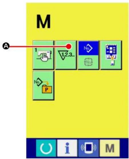
M A 1 1.2.3.. No No P① Display the counter setting screen.

text_image
When you press key.M COUNTER SET- TING button (1.2.3.. A) is displayed. When youpress this button, the counter setting screen is displayed.
text_image
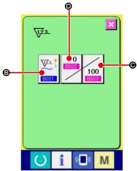
12.3.. B 0 B002 100 B001 B003 C D E i M② Selection of the kinds of counters.
When you press COUNTER TYPE button

(B), the counter type selection screen is
displayed. Select the type of counter you want to use from among the counter types described below.
※ Counter types
No. of pcs. UP counter :

Every time one cycle or one continuous sewing is carried out, the current value on the counter increases. When the current value reaches the set value, the count-up screen is displayed.
No. of pcs. DOWN counter :

Every time one cycle or one continuous sewing is carried out, the current value on the counter decreases. When the current value reaches 0 (zero), the count-up screen is displayed.
Counter unused :


text_image
12.3.. B001 12.3.. 12.3.. 12.3..
text_image
12.3.. B003 0 100 7 8 9 4 5 6 1 2 3 0 ↓ ↑ ←③ Change of counter set value.
When you press COUNTER SETTING button

(©), the counter set value input screen
is displayed.
Input a set value on this screen. If you set the set value to 0 (zero), the count-complete screen will not be displayed.
text_image
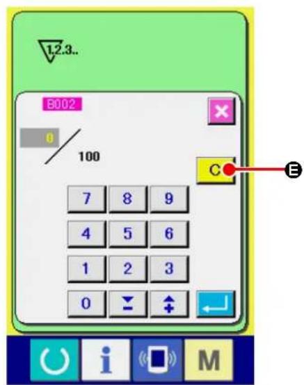
1.2.3.. B002 0 100 7 8 9 4 5 6 1 2 3 0 E④ Change of counter existing value.
When you press COUNTER SETTING button

(D), the current value input screen is
displayed.
On this screen, input the current value.
If you want to clear the counter value, press
CLEAR button (C E).
8-2. Count-up releasing procedure

text_image
AE-200 10 3500 100 A B C D 0 0 0 0 100 12.3. 100 / 100 C EIf the count-complete condition is reached during sewing work, the count-complete screen is displayed and the buzzer sounds. When you press CLEAR button (C E), the counter is reset and the screen returns to the sewing screen. On the sewing screen, the counter starts counting again.
8-3. Method for changing the value of the counter during sewing
text_image
AE-200 3500 A 0 A B C D 0 0 0 0 100 100 110 No P① Displaying the counter value change screen. If you want to correct the counter value due to a stitching failure or the like during sewing work, press COUNTER VALUE CHANGE button (A) on the sewing screen. Then, the counter value change screen is displayed.
② Changing the value on the counter. Input a desired value with numeric keypad ( B ) and -/+ buttons 🚱️ ⬆ (C, D).
text_image
AE-200 B002 0 100 7 8 9 4 5 6 1 2 3 0 C E F C D M③ Confirming the value on the counter. When you press ENTER button (←→), the data you have input is confirmed. If you want to clear the counter value, press CLEAR button C (E).
9. Using the TEMPORARY STOP button
text_image
Diagram showing a control interface with icons for signal processing, display, and function buttons labeled A and M.When you press TEMPORARY STOP button

(A) on the teaching screen, individ-
ual sewing screen or cycle sewing screen, the sewing machine stops and the temporary stop screen "E050" is displayed.

text_image
E050 Temporary stop switch is pressed. BWhen you press RESET button ( B) on
the temporary stop screen, the sewing machine performs thread trimming and the screen returns to the individual sewing editing screen (or the cycle sewing editing screen in the case of cycle sewing).
10. Changing sewing data

text_image
No. No. OOC T AE-200 01 A B C D 10 25 25 25 100 100 100 100 100 100 100 100 110 110 110 110 A P S001 S002 S003 S004 i M① Display the data input screen.
Only on the data input screen (blue), the sewing data can be changed. In the case the sewing screen (green) is displayed, press READY key

to display the data input screen (blue).
② Call the sewing data screen.
When you press SEWING DATA button

(A), the sewing data screen is displayed.
text_image
S001 S002 10 S003 S004 S005 S010 8 8 S011 S020 S021③ Select the sewing data to be changed.
Select the SEWING DATA ITEM button ( Ⓐ) you want to change by pressing UP or DOWN SCROLL button (▲ ▼ B). Be aware that
the data items that are not used because of the sewing pattern shape and that are set to "No function" are not displayed.
text_image
01 S001④ Display the data input screen.
There are two types of sewing data such as the data item the value of which is to be changed and the data item a pictograph for which is to be selected. For the data item the value of which is to be changed is attached with the number, highlighted in pink, as S13
set value can be changed with the +/- buttons displayed on the change screen. For the data item a pictograph for which is to be selected is attached with the number, highlighted in blue, as SFOThis type of data item, you can select one from the pictographs displayed on the change screen.
text_image
01 S003 10 7 8 9 4 5 6 1 2 3 0 ↓ ↑11. Registering a new sewing pattern

text_image
A AE-200 01 10 25 25 25 100 100 100 100 100 100 100 100 110 110 110 110 S001 S002 S003 S004 No P 10 i M① Display the data input screen.
Only on the data input screen (blue), the sewing data can be changed. In the case the sewing screen (green) is displayed, press READY key to display the data input screen (blue).
② Calling up the new pattern registration screen.
When you press NEW PATTERN REGISTRATION button (No. A), the new sewing pattern registration screen is displayed.

text_image
7 8 9 4 5 6 1 2 3 0 B E C D M③ Input the pattern No.
Input a pattern No. you want to newly register with the numeric keypad (B). If you input the pattern No. that has already been registered, the information on that pattern No. will be displayed on the upper part of the screen. Select a pattern No. that is not yet registered and no pattern information is displayed on the screen. It is prohibited to newly register sewing data with the already-registered pattern No.. It is also possible to retrieve an unregistered pattern No. with -/+ buttons (C, D).
④ Determine pattern No.
When you press ENTER button (←→), the pattern No. you have specified is registered and the screen returns to the individual sewing editing screen. If you have entered the already-registered pattern No. and press the ENTER button, the error screen will be displayed.
12. Sewing data list
| No. Item Setting ange Unit Initial value | ||||
| S001 | Start mode | — | — | Manual start |
Manual start  | Selection | |||
Auto start (Once the material is placed on the sewing machine, the machine starts sewing after a preset period of time.)  | ||||
| S002 | Automatic material alignment | — | — | With automatic material alignment |
Without automatic material alignment  | Selection | |||
With automatic material alignment  | ||||
| S003 | Sewing end distance  | 0 to 15 mm | 10 | |
| S004 | Changeover of No. of plies | — | — | Upper and lower materials 2 plies sewing |
Upper and lower materials 2 plies sewing  | Selection | |||
1 piece sewing  | ||||
| S005 | Changeover of upper/lower position of presser foot at stop during sewing | — | — | Presser foot stops at lower position at stop during sewing |
Presser foot stops at lower position at stop during sewing  | Selection | |||
Presser foot stops at upper position at stop during sewing  | ||||
| S006 | Changeover of sewing end | — | — | Sewing ends when all materials move away from the manipulator |
Sewing ends when all materials move away from the manipulator  | Selection | |||
Sewing ends when 1 pc. of material moves away from the manipulator  | ||||
| S010 | Stop after total number of stitches  | 0 to 9999 | Number of stitches | 0 |
| S011 | Stop state after total number of stitches | — | — | Stop after thread trimming |
Stop after thread trimming  | SelectionStop with the needle down | |||
 | ||||
Stop with the needle down and one stitch is additionally sewn  | ||||
| S020 | Upper scrape-out speed of manipulator  | 0 to 9 No unit 8 | ||
| S021 | Upper draw-in speed of manipulator  | 0 to 9 No unit 8 | ||
| S022 | Lower scrape-out speed of manipulator  | 0 to 9 No unit 8 | ||
| S023 | Lower draw-in speed of manipulator  | 0 to 9 No unit 8 | ||
| S024 | Cloth fluff detection level  | 0 to 10 No unit | 0: Cloth fluff detection is not performed. | |
| S025 | Setting of manipulator-pressure intermittent-adjustment section | - | - | No setting of manipulator-pressure intermittent-adjustment section |
No setting of manipulator-pressure intermittent-adjustment section  | ||||
A section setting  | ||||
B section setting  | ||||
C section setting  | ||||
D section setting  | ||||
E section setting  | ||||
F section setting  | ||||
G section setting  | ||||
H section setting  | ||||
I section setting  | ||||
J section setting  | ||||
| S026 | Number of stitches for intermittent interval of upper manipulator pressure [SX6A] | 0 to 10 | Number of stitches | 5The initial value is not displayed when [S25] manipulator presser intermittent adjustment section setting is set to "No setting." |
| S027 | Number of stitches for intermittent interval of lower manipulator pressure  | 0 to 10 | Number of stitches | 5The initial value is not displayed when [S25] manipulator presser intermittent adjustment section setting is set to "No setting." |
| S028 | A speed of machine (rabbit)  | 200 to 3500 sti/min 3500 | ||
| S029 | B speed of machine (turtle)  | 200 to 3500 sti/min 1500 | ||
| S030 | Sewing start - Selection of back tack | — | — | Without reverse feed stitching |
Without reverse feed stitching  | ||||
With reverse feed stitching  | ||||
| S031 | Sewing start - Number of back tack stitches - A  | 0 to 8 | Number of stitches | 4The initial value is not displayed when [S30] reverse feed stitching at the start of sewing is set to "Without reverse feed stitching." |
| S032 | Sewing start - Number of back tack stitches - B  | 0 to 8 | Number of stitches | 4The initial value is not displayed when [S30] reverse feed stitching at the start of sewing is set to "Without reverse feed stitching." |
| S033 | Sewing start - State of back tack manipulator | — | — | Without manipulator |
Without manipulator  | ||||
With manipulator  | ||||
| S034 | Sewing end - Selection of back tack | — | — | Without reverse feed stitching |
Without reverse feed stitching  | ||||
With reverse feed stitching  | ||||
| S035 | Sewing end - Number of back tack stitches - C  | 0 to 8 | Number of stitches | 4The initial value is not displayed when [S34] reverse feed stitching at the end of sewing is set to "Without reverse feed stitching." |
| S036 | Sewing end - Number of back tack stitches - D  | 0 to 8 | Number of stitches | 4The initial value is not displayed when [S34] reverse feed stitching at the end of sewing is set to "Without reverse feed stitching." |
| S037 | Sewing end - State of back tack manipulator | — | — | Without manipulator |
Without manipulator  | ||||
With manipulator  | ||||
| No. Item Setting ange Unit Initial value | |||||
| S040 | Section A - Shirring amount |  | 0 to 8.0 mm | 2.5 Displayed when "absolute value display" is selected in [U06] Shirring display. | |
| Section A - Shirring ratio |  | 0 to 200 Percent | 110 Displayed when "absolute value display" is selected in [U06] Shirring display. | ||
| S041 | Machine head section speed A |  | 200 to 3500 sti/min 3500 | ||
| S042 | Shirring changeover position A (number of stitches) |  | 0 to 9999 | Number of stitches | 0 |
| S043 | Section B - Shirring amount |  | 0 to 8.0 mm | 2.5 Displayed when "absolute value display" is selected in [U06] Shirring display. | |
| Section B - Shirring ratio |  | 0 to 200 Percent | 110 Displayed when "percentage display" is selected in [U06] Shirring display. | ||
| S044 | Machine head section speed B |  | 200 to 3500 sti/min 3500 | ||
| S045 | Shirring changeover position B (number of stitches) | 0 to 9999 | Number of stitches | 0 | |
| S046 | Section C - Shirring amount |  | 0 to 8.0 mm | 2.5 Displayed when "absolute value display" is selected in [U06] Shirring display. | |
 | |||||
| Section C - Shirring ratio | %  | 0 to 200 Percent | 110 Displayed when "percentage display" is selected in [U06] Shirring display. | ||
| S047 | Machine head section speed C | 200 to 3500 sti/min 3500 | |||
| S048 | Shirring changeover position C (number of stitches) |  | 0 to 9999 | Number of stitches | 0 |
| S049 | Section D - Shirring amount |  | 0 to 8.0 mm | 2.5 Displayed when "absolute value display" is selected in [U06] Shirring display. | |
| Section D - Shirring ratio |  | 0 to 200 Percent | 110 Displayed when "percentage display" is selected in [U06] Shirring display. | ||
| S050 | Machine head section speed D |  | 200 to 3500 sti/min 3500 | ||
| No. Item Setting ange Unit Initial value | ||||
| S051 | Shirring changeover position D (number of stitches)  | 0 to 9999 | Number of stitches | 0When the number of stitches is set at 0 (zero), data items [S52] to [S69] are not displayed. |
| S052 | Section E - Shirring amount  | 0 to 8.0 mm | 2.5Displayed when "absolute value display" is selected in [U06] Shirring display. | |
Section E - Shirring ratio  | 0 to 200 Percent | 110Displayed when "percentage display" is selected in [U06] Shirring display. | ||
| S053 | Machine head section speed E  | 200 to 3500 sti/min | ||
| S054 | Shirring changeover position E (number of stitches)  | 0 to 9999 | Number of stitches | 0When the number of stitches is set at 0 (zero), data items [S55] to [S69] are not displayed. |
| S055 | Section F - Shirring amount  | 0 to 8.0 mm | 2.5Displayed when "absolute value display" is selected in [U06] Shirring display. | |
Section F - Shirring ratio  | 0 to 200 Percent | 110Displayed when "percentage display" is selected in [U06] Shirring display. | ||
| S056 | Machine head section speed F  | 200 to 3500 sti/min | ||
| S057 | Shirring changeover position F (number of stitches)  | 0 to 9999 | Number of stitches | 0When the number of stitches is set at 0 (zero), data items [S58] to [S69] are not displayed. |
| S058 | Section G - Shirring amount  | 0 to 8.0 mm | 2.5Displayed when "absolute value display" is selected in [U06] Shirring display. | |
Section G - Shirring ratio  | 0 to 200 Percent | 110Displayed when "percentage display" is selected in [U06] Shirring display. | ||
| S059 | Machine head section speed G  | 200 to 3500 sti/min | ||
| No. Item Setting ange Unit Initial value | |||||
| S060 | Shirring changeover position G (number of stitches) |  | 0 to 9999 | Number of stitches | 0When the number of stitches is set at 0 (zero), data items [S61] to [S69] are not displayed. |
| S061 | Section H - Shirring amount |  | 0 to 8.0 mm | 2.5Displayed when "absolute value display" is selected in [U06]Shirring display. | |
| Section H - Shirring ratio |  | 0 to 200 Percent | 110Displayed when "percentage display" is selected in [U06]Shirring display. | ||
| S062 | Machine head section speed H |  | 200 to 3500 sti/min | ||
| S063 | Shirring changeover position H (number of stitches) |  | 0 to 9999 | Number of stitches | 0When the number of stitches is set at 0 (zero), data items [S64] to [S69] are not displayed. |
| S064 | Section I - Shirring amount |  | 0 to 8.0 mm | 2.5Displayed when "absolute value display" is selected in [U06]Shirring display. | |
| Section I - Shirring ratio |  | 0 to 200 Percent | 110Displayed when "percentage display" is selected in [U06]Shirring display. | ||
| S065 | Machine head section speed I |  | 200 to 3500 sti/min | ||
| S066 | Shirring changeover position I (number of stitches) |  | 0 to 9999 | Number of stitches | 0When the number of stitches is set at 0 (zero), data items [S67] to [S69] are not displayed. |
| S067 | Section J - Shirring amount |  | 0 to 8.0 mm | 2.5Displayed when "absolute value display" is selected in [U06]Shirring display. | |
| Section J - Shirring ratio |  | 0 to 200 Percent | 110Displayed when "percentage display" is selected in [U06]Shirring display. | ||
| S068 | Machine head section speed J |  | 200 to 3500 sti/min | ||
| S069 | Shirring changeover position J (number of stitches) | [J] | 0 to 9999 | Number of stitches | 0 |
| S080 | Section A - Upper manipulator pressure |  | 0 to 200 No | unit 100 | |
| S081 | Section A - Lower manipulator pressure |  | 0 to 200 No | unit 100 | |
| S082 | Upper/lower manipulator pressure change-over position A (number of stitches) |  | 0 to 9999 | Number of stitches | 0 |
| S083 | Section B - Upper manipulator pressure |  | 0 to 200 No | unit 100 | |
| S084 | Section B - Lower manipulator pressure |  | 0 to 200 No | unit 100 | |
| S085 | Upper/lower manipulator pressure change-over position B (number of stitches) |  | 0 to 9999 | Number of stitches | 0 |
| S086 | Section C - Upper manipulator pressure |  | 0 to 200 No | unit 100 | |
| S087 | Section C - Lower manipulator pressure |  | 0 to 200 No | unit 100 | |
| S088 | Upper/lower manipulator pressure change-over position C (number of stitches) |  | 0 to 9999 | Number of stitches | 0 |
| S089 | Section D - Upper manipulator pressure |  | 0 to 200 No | unit 100 | |
| S090 | Section D - Lower manipulator pressure |  | 0 to 200 No | unit 100 | |
| S091 | Upper/lower manipulator pressure change-over position D (number of stitches) |    | 0 to 9999 | Number of stitches | 0When the number of stitches is set at 0 (zero), data items [S92] to [S109] are not displayed. |
| S092 | Section E - Upper manipulator pressure | [4DSG] | 0 to 200 No | unit 100 | |
| S093 | Section E - Lower manipulator pressure |  | 0 to 200 No | unit 100 | |
| S094 | Upper/lower manipulator pressure change-over position E (number of stitches) |    | 0 to 9999 | Number of stitches | 0When the number of stitches is set at 0 (zero), data items [S95] to [S109] are not displayed. |
| S095 | Section F - Upper manipulator pressure |  | 0 to 200 No | unit 100 | |
| S096 | Section F - Lower manipulator pressure |  | 0 to 200 No | unit 100 | |
| S097 | Upper/lower manipulator pressure change-over position F (number of stitches) |    | 0 to 9999 | Number of stitches | 0When the number of stitches is set at 0 (zero), data items [S98] to [S109] are not displayed. |
| S098 | Section G - Upper manipulator pressure |  | 0 to 200 No | unit 100 | |
| S099 | Section G - Lower manipulator pressure |  | 0 to 200 No | unit 100 | |
| S100 | Upper/lower manipulator pressure change-over position G (number of stitches) |  | 0 to 9999 | Number of stitches | 0When the number of stitches is set at 0 (zero), data items [S101] to [S109] are not displayed. |
| S101 | Section H - Upper manipulator pressure |  | 0 to 9999 | Number of stitches | 0When the number of stitches is set at 0 (zero), data items [S101] to [S109] are not displayed. |
| S102 | Section H - Lower manipulator pressure |  | 0 to 9999 | Number of stitches | 0When the number of stitches is set at 0 (zero), data items [S101] to [S109] are not displayed. |
| S103 | Upper/lower manipulator pressure change-over position H (number of stitches) |  | 0 to 9999 | Number of stitches | 0When the number of stitches is set at 0 (zero), data items [S104] to [S109] are not displayed. |
| S104 | Section I - Upper manipulator pressure |  | 0 to 200 No | unit 100 | |
| S105 | Section I - Lower manipulator pressure |  | 0 to 200 No | unit 100 | |
| S106 | Upper/lower manipulator pressure change-over position I (number of stitches) |  | 0 to 9999 | Number of stitches | 0When the number of stitches is set at 0 (zero), data items [S107] to [S109] are not displayed. |
| S107 | Section J - Upper manipulator pressure |  | 0 to 200 No | unit 100 | |
| S108 | Section J - Lower manipulator pressure |  | 0 to 200 No | unit 100 | |
| S109 | Upper/lower manipulator pressure changeover position J (number of stitches) |  | 0 to 9999 | Number of stitches | 0 |
| S120 | Speed of stitch of the machine head after the detection of material end |  | 200 to 3500 sti/min 1500 | ||
| S130 | Selection of stacker operation | — | — | StopThis item is not dis-played when MEMO-RY switch [U10] is set to "Without stacker." | |
| Stop |  | ||||
| Operate |  | ||||
| No. Item Setting ange Unit Initial value | ||||
| S131 | Stacker operating position  | 0 to 999 No unit | 0This item is not displayed when MEMORY switch [U10] is set to "Without stacker." | |
| S132 | Selection of the number of times of stack-er operation  | 1 to 10 No unit | 1This item is not displayed when MEMORY switch [U10] is set to "Without stacker." | |
13. Copying sewing pattern
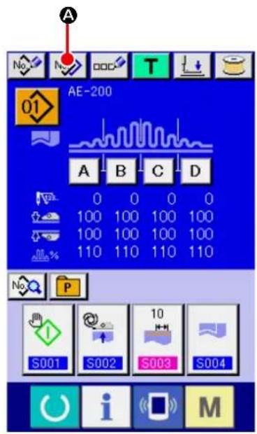
text_image
A No N OOC T 01 AE-200 A B C D 0 0 0 0 100 100 100 100 100 100 100 100 110 110 110 110 S001 S002 S003 S004 M S004It is possible to copy the sewing data of the already-registered pattern No. to an unregistered pattern No. Copy of the sewing pattern by overwriting is prohibited. If you want to overwrite the existing pattern data, erase that pattern first. Then, carry out overwriting.
→ Refer to "VI-4. Selecting a pattern" p.46.
① Display the data input screen.
Only on the data input screen (blue), the sewing data can be changed. In the case the sewing screen (green) is displayed, press READY key to display the data input screen (blue).
② Calling up the pattern copy screen.
When you press PATTERN COPY button

(A), the pattern copy (copy source selection) screen is displayed.
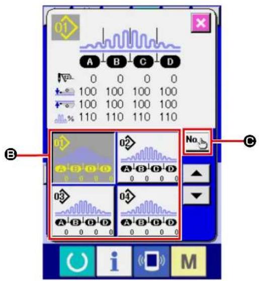
text_image
01 A B C D 0 0 0 0 100 100 100 100 100 100 100 100 110 110 110 110 B 02 No C A B C D 03 A B C D 04 A B C D 0 0 0 0 0 0 0 0 0 0 0 0 0 0 0 0 0 0 0 0 0 0 0 0 0 0 0 0 0 0 0 0 0 0 0 0 0 0 0 0 0 0 0 0 0 0 0 0 0 0 0③ Select the source pattern No. for copying.
Select a source pattern No. from PATTERN LIST buttons (B). Then, press COPY DESTINATION INPUT button (No.h) to display the copy destination input screen.
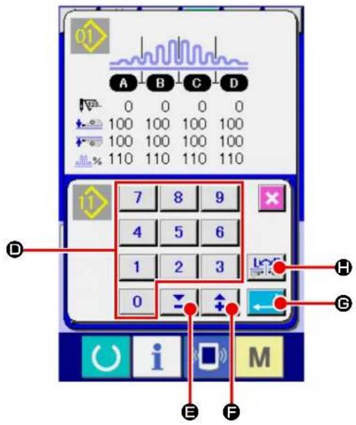
text_image
01 A B C D 0 0 0 0 100 100 100 100 100 100 100 100 110 110 110 110 7 8 9 4 5 6 1 2 3 0 H G E F M④ Input the pattern No. of copy destination.
Input a copy destination pattern No. with the numeric keypad (ID). It is possible to retrieve an unused pattern No. with -/+ buttons
(E, F). It is possible to select whether or not the data is copied with its right and left portions changed over with RIGHT/LEFT CHANGE-OVER key
⑤ Start copying.
When you press ENTER button (←→), copying is started. Approximately two seconds later, the screen returns to the pattern copy (copy source selection) screen while displaying the copied pattern No. in the selected state. If you have input the existing pattern No. and press the ENTER button, the error screen will be displayed.
14. Registering the direct pattern
It is recommended to register the pattern No. you use frequently with the PATTERN DIRECT button. Once you have registered a pattern No. with the PATTERN DIRECT button, you can select the pattern No. with ease only by pressing that button.
14-1. Registration procedure
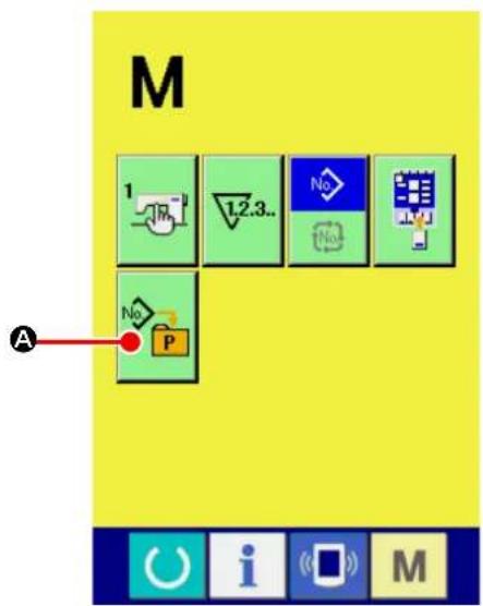
text_image
M 1 L2.3.. No No A No P① Displaying the direct pattern registration screen. When you press key, DIRECT PATTERN REGISTRATION button (A) is displayed on the screen. The direct pattern registration screen is displayed by pressing this button.

text_image
No P B 01 02 03 04 05 06 07 08 09 10② Selecting the button to be used for registration. As many as 10 direct patterns can be registered. Ten direct patterns (B) are displayed on the screen. When you press the button displayed at a desired location on the screen, the pattern No. list screen is displayed.

text_image
No P 02 A B C D 3 0 0 0 03 A B C D 4 0 0 0 04 A B C D 5 0 0 0 05 A B C D 6 0 0 0 06 A B C D 7 0 0 0 No E D F i M③ Selecting the pattern No. to be registered.
Select the pattern No. you want to register from among the PATTERN No. buttons (●). If you press the PATTERN No. button you have selected again, your selection will be canceled. The PATTERN No. button (●) will be changed over in sequence by pressing the UP/DOWN SCROLL buttons (●).
When you press PATTERN No. INPUT button No (E), the pattern No. input screen is displayed. Select the pattern you want to register. Then, press ENTER button (F) to register the pattern you have selected.
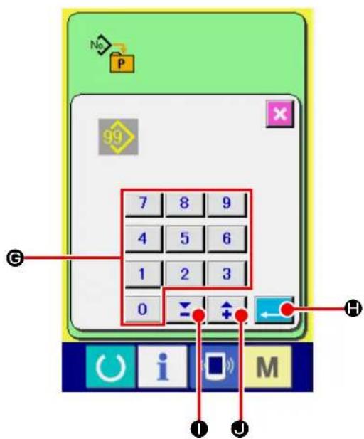
text_image
No P 99 7 8 9 4 5 6 1 2 3 0 ← H i M I J④ Input the pattern No.
When you press PATTERN No. INPUT button (E), the pattern No. input screen is displayed. On this screen, you can directly input the number you want to select with the numeric keypad. Input the pattern No. with numeric keypad (G). It is also possible to retrieve an existing pattern No. with -/+ buttons ( \boxed{\boxed{\boxed{\boxed{\boxed{\boxed{\boxed{\boxed{\boxed{\boxed{\boxed{\boxed{\boxed{\boxed{\boxed{\boxed{\boxed{\boxed{\boxed{\boxed{\boxed{\boxed{\boxed{\boxed{\boxed{\boxed{\boxed{\boxed{\boxed{\boxed{\boxed{\boxed{\boxed{\boxed{\boxed{\boxed{\boxed{\boxed{\boxed{\boxed{\boxed{\boxed{\boxed{\boxed{\boxed{\boxed{\boxed{\boxed{\boxed{boxed{\boxed{boxed{\boxed{boxed{\boxed{boxed{\boxed{boxed{\boxed{boxed{\boxed{boxed{\boxed{boxed{\boxed{boxed{\boxed{boxed{\boxed{boxed{\boxed{boxed{\boxed{boxed{\boxed{boxed{\boxed{boxed{\boxed{boxed{\boxed{boxed{\boxed{boxed{\boxed{boxed{\boxed{boxed{\boxed{boxed{\boxed{boxed{\boxed{boxed{\boxed{boxed{\boxed{boxed{\boxed{\boxed{boxed{\boxed{boxed{\boxed{boxed{\boxed{boxed{\boxed{boxed{\boxed{boxed{\boxed{boxed{\boxed{boxed{\boxed{boxed{\boxed{boxed{\boxed{boxed{\boxed{boxed{\boxed{boxed{\boxed{boxed{\boxed{boxed{\boxed{boxed{\boxed{boxed{\boxed{boxed{\boxed{boxed{\boxed{boxed{\boxed{boxed{\boxed{boxed{\boxed{boxed{\boxed{boxed}{(\underline{{}}}}}}}}}}}}}}}}}}}}}}}}}}}}}}}}}}}}}}}}}}}}}}}}}}}}}}}}}}}}}}}}}}}}}}}}}}}}}}}}}}}}}}}}}}}}}}}}}}}}}}}}}}}}}}}}}}}}}}}}}}}}}}}}}}}}}}}}}}}}}}}}}}}}}}}}}}}}}}}}}}}}}}}}}}}}}}}}}}}}}}}}}}}}}}}}}}}}}}}}
When you press ENTER button (←→), the pattern No. you have specified is selected. If you have input unregistered pattern No. and press the ENTER button, the error screen will be displayed.
14-2. State of registration at the time of purchase
Pattern Nos. 1 to 3 have been factory-registered at the time of purchase.
15. Registering the sewing data with the CUSTOMIZATION button
It is recommended to register the parameter you use frequently with the CUSTOMIZATION button.
Once you have registered a parameter with the CUSTOMIZATION button, you can call up the change screen for the registered parameter only by pressing that button on the data input screen.
15-1. Registration procedure

text_image
M 1 No A No P① Displaying the customization pattern registration screen.
When you press key, the CUSTOMIZA-
TION PATTERN REGISTRATION button

(A) is displayed on the screen. The customization pattern registration screen is displayed by pressing this button.

text_image
A B C D 0 0 0 0 100 100 100 100 100 100 100 100 110 110 110 110 S001 S002 S003 S004 B i M② Selecting the button to be used for registration.
As many as four CUSTOMIZATION buttons can be registered. Four CUSTOMIZATION REG-ISTRATION buttons (B) are displayed on the screen. When you press the button displayed at a desired location on the screen, the sewing data list screen is displayed.

text_image
S001 S002 S003 S004 S005 S010 8 8 S011 S020 S021③ Selecting the sewing data to be registered.
Select the sewing data you want to register by means of the SEWING DATA button (☑). If you press the button you have selected again, you selection will be cancelled.
④ Registering the sewing data with the CUS-TOMIZATION button.
When you press ENTER button (←→D), registration of the sewing data is completed and the CUSTOMIZATION button registration screen is displayed. The sewing data you have registered is displayed on the CUSTOMIZATION button.
15-2. State of registration at the time of purchase
At the time of purchase, the following four parameters have been factory-registered in the order from left to right.
S001
Start mode
S002
Automatic material alignment
S003
Sewing end distance
S004
Changeover of the number
of plies of material


16. Changing sewing mode

text_image
M A 1.2.3.. No P① Displaying the sewing mode selection screen.
When you press key, SEWING MODE
SELECT button (A) is displayed on the upper part of the screen. The sewing mode selection screen is displayed by pressing this button.
The appearance of the SEWING MODE SELECT button differs with the currently-selected sewing mode.
Independent sewing button :

In the case cycle sewing is selected :

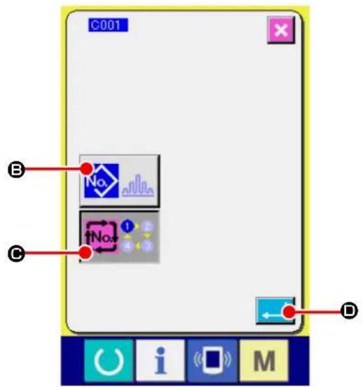
text_image
C001 No. No. D B C D i M② Select the sewing mode.
Select the sewing mode you want to use for sewing.
Independent sewing button (B):

In the case cycle sewing is selected (©):

③ Determine the sewing mode.
When you press ENTER button (←→), the sewing mode changing procedure is terminated. When you press key, the data input screen is displayed under the sewing mode you have selected.
17. On the LCD display for cycle sewing
This sewing machine is able to carry out two or more pieces of sewing pattern data cyclically in sequence. As many as 30 patterns can be input. Use the cycle sewing when you sew several patterns that differ in shape on a sewing product. In addition, as many as 20 cycles can be registered. Register a new sewing pattern or copy an existing sewing pattern as appropriate.
→ Refer to "VI-11. Registering a new sewing pattern" p.59 and "VI-13. Copying sewing pattern" p.69.
17-1. Data input screen
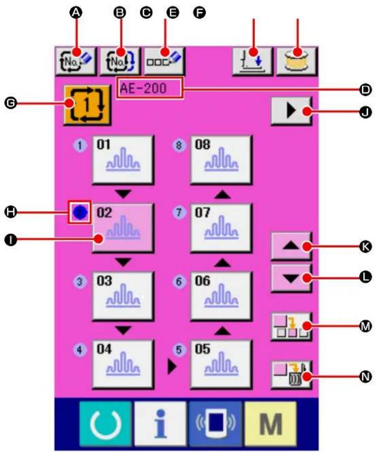
flowchart
graph TD
    A["No."] --> B["No."]
    B --> C["DOC"]
    C --> D["AE-200"]
    D --> E["D"]
    D --> F["J"]
    D --> G["G"]
    H["1"] --> I["01"]
    I --> J["02"]
    J --> K["03"]
    K --> L["04"]
    L --> M["05"]
    M --> N["06"]
    N --> O["07"]
    O --> P["08"]
    P --> Q["End"]
| Button and display Description | ||
| A | NEW CYCLE DATA REGISTRATION button | To be used to display the new cycle data No. registration screen. |
| B | CYCLE DATA COPY button To be | used to display the cycle data No. copy screen. |
| C | CYCLE DATA NAME INPUT button | To be used to display the cycle data name input screen.→ Refer to "VI-5. Naming the pattern" p.48 . |
| D | Cycle data name display | The name entered to the currently-selected cycle data is displayed in this field. |
| E | PRESSER DOWN button To be used to display the presser foot lowering screen. The needle is moved to the right.To raise the presser, press the presser up button displayd in the presser down screen.* When performing threading in this state, turn OFF the power before performing. | |
| F | BOBBIN WINDING button Bobbin thread can be wound.→ Refer to "VI-7. Winding a bobbin" p.51 . | |
| G | CYCLE DATA No. SELECT button | To be used to display the currently-selected cycle data number on the button. When this button is pressed, the cycle data No. change screen is displayed. |
| H | Sewing order display The sewing order of the pattern data you have input is displayed. The pattern to be sewn firstly after the screen is changed over to the sewing screen is displayed in blue.* The button and display H and I are displayed by the number of patterns you have input. | |
| I | PATTERN SELECT button | The pattern No. and type of pattern you have registered are displayed on the button according to the "H: Sewing order display". When this button is pressed, the pattern selection screen is displayed.* The button and display H and I are displayed by the number of patterns you have input. |
| J | NEXT PAGE DISPLAY button This button is displayed in the case the number of patterns registered with the cycle data is eight or more. | |
| K | UP SCROLL button To be used to select the one previous pattern No. | |
| L | DOWN SCROLL button To be used to select the next pattern No. | |
| M | STEP INSERT button To be used to insert a step just before the currently-selected pattern No. | |
| N | STEP DELETE button To be used to delete the currently-selected step. | |
17-2. Sewing screen
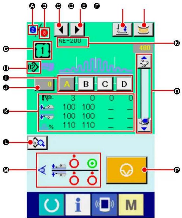
text_image
A B C D E F 2 8 AE-200 400 G H 02 I J 0 A B C D 3 0 0 0 100 100 100 100 110 110 K L M P O i M| Button and display Description | |
| A | Sewing order display The sewing order of the currently-sewn pattern is displayed in this field. |
| Button and display Description | ||
| B | Total number of registered pat-tens display | The total number of patterns registered with the currently-sewn cycle num-ber is displayed. |
| C | SEWING ORDER RETURN button | To be used to display the cycle data name input screen.→ Refer to "VI-5. Naming the pattern" p.48 . |
| D | SEWING ORDER PROCEED button | To be used to proceed the pattern to be sewn |
| E | PRESSER DOWN button Presser | down screen is displayed and the needle moves to the right side. To raise the presser, press the presser up button display in the presser down screen.* When performing threading in this state, turn OFF the power before per-forming. |
| F | BOBBIN WINDING button Bobbin | thread can be wound.→ Refer to "VI-7. Winding a bobbin" p.51 . |
| G | Cycle data No. display The cycle | data number that is currently sewn is displayed in this field. |
| H | Pattern No. display The pattern No. | that is currently sewn is displayed in this field. |
| I | PATTERN SECTION button The | pattern data that is currently sewn.→ Refer to "VI-6. Sewing data editing function" p.49 . |
| J | COUNTER VALUE CHANGE button | To be used to display the current counter value on the button. The counter value change screen is displayed by pressing this button.→ Refer to "VI-8. Using counter" p.53 . |
| K | Sewing data display The currently-sewn pattern data is displayed in this field.• Number of stitches for section• Pressure values of the upper and lower manipulators• Upper shirring amount | |
| L | SEWING DATA CHANGE button | To be used to display the sewing data change screen for the pattern data that is input at the cursor position. |
| M | Manipulator sensor status The manipulator sensor status during sewing is displayed. | |
| N | Cycle data name display | The name input in the currently-sewn cycle data is displayed in this field. |
| O | SPEED VARIABLE RESISTOR | The number of revolutions of the sewing machine can be changed with this variable resistor. |
| P | TEMPORARY STOP button | To be pressed to stop the sewing machine. |
18. Performing the cycle sewing
Firstly, change the sewing mode to the cycle sewing mode before starting setting of the cycle sewing data. Refer to "VI-16. Changing sewing mode" p.75.
18-1. Selection of cycle data

flowchart
graph TD
    A["1"] --> B["01"]
    B --> C["02"]
    C --> D["03"]
    D --> E["04"]
    E --> F["05"]
    F --> G["06"]
    G --> H["07"]
    H --> I["08"]
    I --> J["1"]
    style A fill:#f9f,stroke:#333
    style J fill:#ccf,stroke:#333
① Display the data input screen.
The cycle data number can be selected only on the data input screen (pink). In the case the sewing screen (green) is displayed, press READY key to display the data input screen (pink).
② Calling up the cycle No. selection screen.
When you press CYCLE DATA No. button

(A), the cycle data No. selection screen is displayed. The currently-selected cycle data number and its content are displayed on the upper part of the screen. Other CYCLE DATA No. buttons that you have registered are displayed on the lower part of the screen.
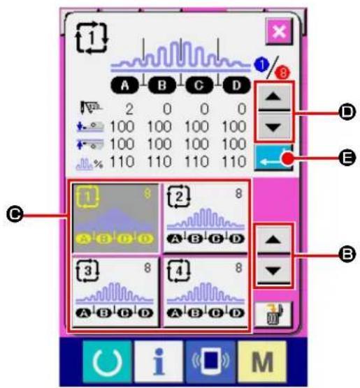
text_image
Screenshot of a digital audio workstation interface with labeled controls and waveform displays③ Selecting the cycle data number.
When you press UP/DOWN SCROLL buttons

text_image
(B), the registered CYCLE DATA No. button (C) is changed over in sequence.In this state, press CYCLE DATA No. button ( © ) you want to select.
When you press STEP CHECK button

(D), the stitch shape or other data on the sewing pattern you have registered with cycle data is changed over and displayed in sequence.
④ Confirming the cycle data number.
When you press ENTER button (←→), the cycle data No. selection screen is closed to terminate the cycle data number selection procedure.
18-2. Editing procedure of the cycle sewing
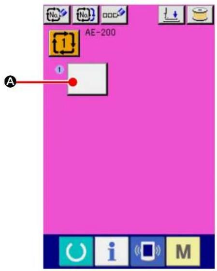
text_image
AE-200 A① Display the data input screen.
Cycle data can be input only on the data input screen (pink). In the case the sewing screen
(green) is displayed, press READY key

to display the data input screen (pink).
In the initial state of the sewing machine, no pattern No. has been registered. Therefore, the first PATTERN SELECT button is displayed in blank.
② Calling up the cycle No. selection screen.
When you press PATTERN SELECT button
(A), the pattern No. selection screen is displayed.
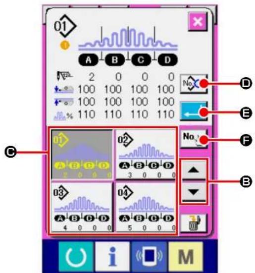
text_image
01 A B C D 2 0 0 0 100 100 100 100 100 100 100 100 110 110 110 110 C 02 A B C D 3 0 0 0 03 04 A B C D A B C D 4 0 0 0 5 0 0 0 D E F B i M③ Selecting the cycle data number.
When you press UP/DOWN SCROLL buttons

(B), the registered PATTERN No.
button (C) is changed over in sequence.
It is also possible to display the pattern No. input screen with NUMERIC INPUT button

(⑤) and directly enter a pattern No.. The
content of the pattern data is displayed o the button. In this state, press the PATTERN No. button you want to select.
④ Editing sewing data of the pattern.
When you press SEWING DATA EDIT button

(D), the sewing data screen is displayed
to allow you to edit sewing data of the currently-selected pattern.
⑤ Editing sewing data of the pattern.
When you press ENTER button (←→), the pattern No. selection screen is closed to terminate the pattern No. selection procedure.
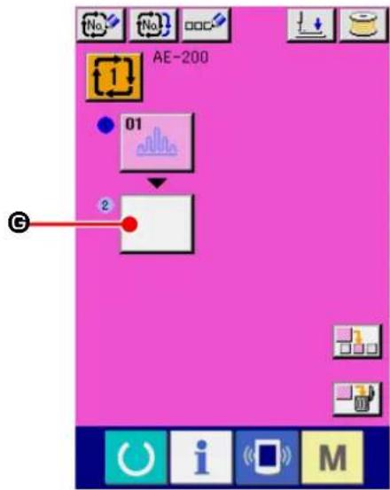
text_image
AE-200 01 2⑥ Repeating steps ② to ④ by the number of cycle patterns you want to register.
Upon completion of registration of the first cycle pattern, second PATTERN SELECT button

(G) is displayed.
Repeat steps ② to ④ by the number of cycle patterns you want to register.

text_image
AE-200 01 8 08 02 7 07 3 03 6 06 4 04 5 05 K J H I⑦ Selecting the cycle data number.
You can select the PATTERN No. button by pressing UP/DOWN SCROLL buttons

(H). The PATTERN No. button you
have selected is displayed in pink as

When you press PATTERN No. INSERT button

(1), a step is inserted before the current-
ly-selected pattern No. (displayed in pink).
If you press the currently-displayed PATTERN
No. button (J) to select another pattern No., the pattern No. will be changed over.
In the case the cycle data you have created extends to multiple screens, the next screen can be displayed with SCREEN SCROLL button
▶ (K).
18-3. Editing the currently-selected sewing data in cycle data

text_image
01 S001 S002 10 S003 S004 S005 S010 8 8 S011 S020 S021 A B i M① Calling up the cycle data No. selection screen.
Carry out steps ① to ④ as described in "VI-18-2. Editing procedure of the cycle sewing" p.80 to display the screen for editing the pattern sewing data.
② Selecting the sewing data to be changed.
Press UP/DOWN SCROLL buttons

(B) to select DATA ITEM button (A) you want to change. Be aware that the data item that is not used because of the sewing pattern shape and that is set to "No function" are not displayed.
③ Changing the data.
There are two types of sewing data such as the data item the value of which is to be changed and the data item a pictograph for which is to be selected. For the data item the value of which is to be changed is attached with the number, highlighted in pink, as S Its set value can be changed with the +/- button displayed on the change screen. For the data item a pictograph for which is to be selected is attached with the number, highlighted in blue, as S For this type of data item, you can select one from the pictographs displayed on the change screen.
→ Refer to "VI-12. Sewing data list" p.60 for details of the sewing data.
18-4. Method for deleting the cycle data

text_image
1 A B C D 2 0 0 0 100 100 100 100 100 100 100 100 110 110 110 110 B 3 8 4 8 A B D D A B D D A B D D A B D D① Calling up the cycle data No. selection screen.
Carry out steps ① to ③ as described in "VI-18-1. Selection of cycle data" p.79 to display the screen for editing the pattern sewing data.
② Deleting the cycle data.
When you press DATA DELETE button

(A), the cycle data deletion confirmation popup appears on the screen.
When you press ENTER button (←) in this state, the cycle data step you have selected is deleted.
If you press CANCEL button ( ✗ Ⓓ), the screen will return to the cycle data selection screen without deleting the cycle data you have selected.

text_image
1 A B C D 2 0 0 0 100 100 100 100 100 100 100 100 110 110 110 110 ? No. C D C U I S M18-5. Method for deleting a step of the cycle data
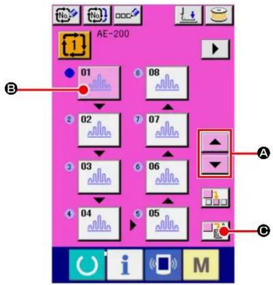
text_image
AE-200 01 08 02 07 03 06 04 05 A B C① Selecting the cycle data No. selection screen.
Carry out steps ① to ② as described in "VI-18-1. Selection of cycle data" p.79 to place the cycle data that contains the step you want to delete in the selected state.
② Displaying the pattern No. selection screen.
Press UP/DOWN SCROLL buttons

(A) to place the PATTERN SELECT button for the step you want to delete in selected state

(B). In this state, the data step deletion is displayed by pressing STEP DELETE (☐).
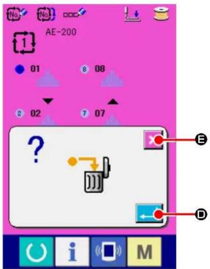
text_image
No. No. DDC AE-200 1 01 8 08 2 02 7 07 ? E D U i (M)③ Deleting the step in the selected cycle data.
When you press ENTER button (←→), the cycle data step you have selected is deleted.
If you press CANCEL button ( ✗ E), the screen will return to the cycle data selection screen without deleting the cycle data you have selected.
19. Changing the memory switch data

text_image
M A 1 2.3.. No No No P① Display the data input screen.
When you press key, MEMORY switch

(A) is displayed on the screen.
When you press this button, the memory switch data list screen is displayed.
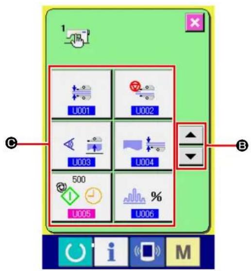
② Selecting the MEMORY switch button you want to change.
Press UP/DOWN SCROLL button

(B)
to select the DATA ITEM button (©) you want to change.
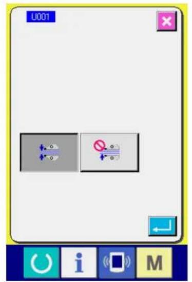
text_image
U001 + - + - + -③ Changing the MEMORY switch data. There are two types of MEMORY switch data such as the data item the value of which is to be changed and the data item a pictograph for which is to be selected. For the data item the value of which is to be changed is attached with the number, highlighted in pink, as \$005 Its set value can be changed with the +/- button displayed on the change screen. For the data item a pictograph for which is to be selected is attached with the number, highlighted in blue, as LFor this type of data item, you can select one from the pictographs displayed on the change screen.

text_image
U005 500 7 8 9 4 5 6 1 2 3 0 ↕ ↑→ Refer to "VI-20. List of memory switch data" p.87 for details of the MEMORY switch data.
20. List of memory switch data
20-1. Level 1
Memory switch data (Level 1) are the operation data shared by sewing machines. They are common to all sewing patterns.
| No. Item Setting range Unit Initial value | |||||
| U001 | Selection of the manipulator operation | — | — | Manipulator is operative | |
Manipulator is operative  | |||||
Manipulator is inoperative  | |||||
| U002 | Selection of the operation at sewing end | — | — | Standard operation | |
Standard operationSewing machine finishes sewing regard-less of the material end sensor  | |||||
When no lower cloth remains on the sewing machine though the material end sensor is detecting the material, the sewing machine stops after thread trimming without sewing back tack stitches.  | |||||
| U003 | Selection of the material placement condition | — | — | The sensor assumes that the material is placed on the sewing machine only when the material is inserted under the sensor until it will go no further. | |
The sensor assumes that the material is placed on the sewing machine only when the material is inserted under the sensor until it will go no further.  | |||||
| The sensor assumes that the material is placed on the sewing machine when the material is placed just before the sensor. [ZKZB] | |||||
| U004 | Selection of one piece sewing mode | — | — | Lower manipulator | |
Lower manipulator (normal)  | |||||
| One piece of material is sewing using the upper manipulator. [BT3D] | |||||
| U005 | Automatic starting time  | 100 to 500 msec 500 | |||
| U006 | Changeover of shirring display | — | — | Displayed in percent figures | |
| Absolute value displayShirring amount (mm) is displayed using sewing data items [S40, S43, S46, S49, S52, S55, S58, S61, S64 and S67]. The shirring amount does not change even if the bottom feed amount is changed by means of the dial. [AB43] | |||||
Percentage display (with respect to the bottom feed amount)Shirring ratio (%) is displayed using sewing data items [S40, S43, S46, S49, S52, S55, S58, S61, S64 and S67]. If the bottom feed amount is changed by means of the dial, the shirring amount will be automatically changed to the value corresponding to the preset ratio (%).  | |||||
| U007 | Selection of the material presser operation | — | — | The material press-er operates. | |
The material presser operates when the stacker operates.  | |||||
The material presser operation is prohibited when the stacker operates.  | |||||
| U010 | Implementation/type of the stacker | — | — | Without stackerWhen "Without stacker" is selected, the sewing data items [S130], [S131] and [S132] are not displayed. | |
| Without stacker [XASD] | |||||
Air stacker is implemented  SS51 SS51 | |||||
Standard bar stacker is implemented  | |||||
| U011 | Stacker timer 1  [1] [1] | 0.0 to 9.9 0.1 sec | 0.5This item is not displayed when the stacker is set to "Without stacker." | ||
| U012 | Stacker timer 2  [2] [2] | 0.0 to 9.9 0.1 sec | 0.5This item is not displayed when the stacker is set to "Without stacker." | ||
| U013 | Stacker timer 3  [3] [3] | 0.0 to 9.9 0.1 sec | 1.5This item is not displayed when the stacker is set to "Without stacker." | ||
| U015 | Soft start speed setting for the 1st stitch  [4] [4] | 200 to 3500 sti/min | 800 | ||
| U016 | Soft start speed setting for the 2nd stitch  [4] [4] | 200 to 3500 sti/min | 800 | ||
| U017 | Soft start speed setting for the 3rd stitch  [4] [4] | 200 to 3500 sti/min | 2000 | ||
| U018 | Soft start speed setting for the 4th stitch  [4] [4] | 200 to 3500 sti/min | 3000 | ||
| U019 | Soft start speed setting for the 5th stitch  [4] [4] | 200 to 3500 sti/min | 3500 | ||
| U020 | Counter updating unit [4HEX] [1.2] | 1 to 30 | No unit 1 | ||
| U021 | Selection of with/without the bobbin thread remaining amount detection  | — | — | Without the bobbin thread remaining amount detecting device | |
Without the bobbin thread remaining amount detecting device  [4] [4] | |||||
The bobbin thread remaining amount detecting device is implemented.  [4] [4] | |||||
| U022 | Number of times of bobbin thread re-maining amount detection | 0 to 19 | Number of times | 1In the case the bobbin thread re-maining amount detecting function is disabled, the error popup screen will not be displayed. | |
| U023 | Selection of thread breakage detecting operation | — | — | Without the bobbin thread remaining amount detecting device | |
| Without the bobbin thread remaining amount detecting device | |||||
| The bobbin thread remaining amount de- tecting device is implemented. | |||||
| U024 | Lowering of needle at the material placement | — | — | Material placement with the needle lift-ed | |
| Material placement with the needle lifted | |||||
| Material placement with the needle low- ered (*1) If you press the START button before placement of the material on the sewing machine, the needle bar will come down. | |||||
| U025 | Selection of section | — | — | Shirring amount section and manip- ulator pressure sec-tion are identical. | |
| Shirring amount section and manipulator pressure section are identical. | |||||
| Shirring amount section and manipulator pressure section are separate. | |||||
| U027 | Selection of the material presser timing | The material press- er operates after the sewing machine has sewn the pre-determined number of stitches or after the sewing machine stops and carries out thread trimming. | |||
| The material presser operates after the sewing machine has sewn the predeter-mined number of stitches or after the sew-ing machine stops and carries out thread trimming. | |||||
| The material presser operates when the material has moved out of the material sensor. | |||||
| U500 | Language selection | 日本語 | Japanese | Not selected (dis-played in English) | |
| English | English | ||||
| 中文简体字 | Simplified Chinese | ||||
| Español | Spanish | ||||
| Tiếng Việt | Vietnamese | ||||
(*1) It is possible to place the material on the sewing machine using the needle bar as reference with the needle bar lowered. Since the needle bar stops when it has passed its lowest point, adjust the upper position of the presser foot. (Refer to "VIII-1. Adjusting the presser foot lifting lever" p.159.) When you press the START button after having place the material on the sewing machine, the sewing machine starts sewing.
20-2. Level 2
Memory switch data (level 2) can be edited when pressing MODE switch for as long as 6 seconds.
| No. Item Setting range Unit Initial value | ||||
| K002 | Setting of max. limited speed  | 200 to 3500 st/min 3500 | ||
| K004 | Waiting time for coming-down of the presser foot  | 0 to 100 msec 50 | ||
| K005 | Manipulator pressure upper correction value  | -30 to 30 | — | 0 |
| K006 | Manipulator pressure lower correction value  | -30 to 30 | — | 0 |
| K007 | Setting of manipulator sensor type  | 0 to 3 | — | 0 |
| K008 | Start of sewing - Machine head rotating speed for back tacking  | 200 to 1900 st/min 800 | ||
| K009 | End of sewing - Machine head rotating speed for back tacking  | 200 to 1900 st/min 800 | ||
| K010 | Number of correction stitches A for reverse-feed stitching at the start of sewing  | 0 to 5 | Number of times | 0 |
| K011 | Number of correction stitches B for reverse-feed stitching at the start of sewing  | 0 to 5 | Number of times | 0 |
| K012 | Number of correction stitches C for reverse-feed stitching at the end of sewing  | 0 to 5 | Number of times | 0 |
| K013 | Number of correction stitches D for reverse-feed stitching at the end of sewing  | 0 to 5 | Number of times | 0 |
| K014 | Correction angle A for back-tack sole-noid output at the start of sewing  | -36 to 36 | ×10 degrees | 0 |
| K015 | Correction angle B for back-tack sole-noid output at the start of sewing  | -36 to 36 | ×10 degrees | 0 |
| K016 | Correction angle D for back-tack sole-noid output at the start of sewing  | -36 to 36 | ×10 degrees | 0 |
| K017 | Set value for the needle bar stopping position  | -50 to 50 Degrees 0 | ||
21. Setting the upper shirring
The upper shirring amount can be selected with MEMORY switch "U06" between two different methods; i.e., "Specify the top feed amount" (indicated in mm) and "Specify the percentage with respect to the bottom feed amount" (indicated in %).
It is possible to divide the upper shirring section into as many as 10 sections and specify the shirring amount for the respective sections separately.
At the same time, the machine head speed can be set separately for those sections.
Example: In the case only one section of a seam is shirred shirring
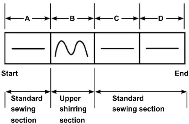
text_image
A B C D Start End Standard sewing section Upper shirring section Standard sewing sectionFor the shirring amount, the "absolute value display" is to be selected in the data item "U06" and four sections A to D are to be used.
| Number | Setting item Set value Remarks | ||
| S40 | Section A - Shirring amount 2.5 Top feed amount | should be set at | 2.5 mm. |
| S41 | Machine head section speed A 2500 | The machine head speed should be set at 2,500 sti/min. | |
| S42 | Upper shirring changeover position A (the number of stitches) | 40 40-stitches section | |
| S43 | Section B - Shirring amount 3.7 Top feed amount | should be set at | 3.7 mm. |
| S44 | Machine head section speed B 2500 | The machine head speed should be set at 2,500 sti/min. | |
| S45 | Upper shirring changeover position B (the number of stitches) | 40 40-stitches section | |
| S46 | Section C - Shirring amount 2.5 Top feed amount | should be set at | 2.5 mm. |
| S47 | Machine head section speed C 2500 | The machine head speed should be set at 2,500 sti/min. | |
| S48 | Upper shirring changeover position C (the number of stitches) | 20 20-stitches section | |
| S49 | Section D - Shirring amount 2.5 Top feed amount | should be set at | 2.5 mm. |
| S50 | Machine head section speed D 3500 | The machine head speed should be set at 3,500 sti/min. | |
| S51 | Upper shirring changeover position D (the number of stitches) | 0 | To the end |

When the upper shirring changeover position (the number of stitches) is set at "0" the upper shirring section continues to the end. The sewing machine does not move to the next section.
22. Setting the manipulator pressure
One seam can be divided into 10 upper/lower manipulator pressure section subsections at the maximum. The pressure value can be separately set for the respective sections.
Example: In the case one seam is sewn with the one same pressure
| Number Setting item Set value Remarks | |||
| S80 Section A - Upper manipulator pressure 85 | The material is clamped with the pressure value 85. | ||
| S81 Section A - Lower manipulator pressure 98 | The material is clamped with the pressure value 98. | ||
| S82 | Manipulator pressure changeover position A (the number of stitches) | 0 The section up to the end of sewing | |
| S83 Section B - Upper manipulator pressure xxx Any value will do | |||
| S84 Section B - Lower manipulator pressure xxx Any value will do | |||
| S85 | Manipulator pressure changeover position B (the number of stitches) | xxx Any value will do | |
| S86 Section C - Upper manipulator pressure xxx Any value will do | |||
| S87 Section C - Lower manipulator pressure xxx Any value will do | |||
| S88 | Manipulator pressure changeover position C (the number of stitches) | xxx Any value will do | |
| S89 Section D - Upper manipulator pressure xxx Any value will do | |||
| S90 Section D - Lower manipulator pressure xxx Any value will do | |||
| S91 | Manipulator pressure changeover position D (the number of stitches) | xxx Any value will do | |

When the manipulator changeover position (the number of stitches) at "0," the manipulator pressure section continues to the end. The sewing machine does not move to the next section.
Example: In the case one seam is divided into five sections and those section are respectively sewn with different pressure values.
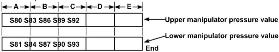
text_image
A B C D E S80 S83 S86 S89 S92 Upper manipulator pressure value Lower manipulator pressure value S81 S84 S87 S90 S93 End| Number Setting item Set value Remarks | |||
| S80 Section A - Upper manipulator pressure 85 | The material is clamped with the pressure value 85. | ||
| S81 Section A - Lower manipulator pressure 98 | The material is clamped with the pressure value 98. | ||
| S82 | Manipulator pressure changeover position A (the number of stitches) | 10 10-stitches section | |
| S83 Section B - Upper manipulator pressure 80 | |||
| S84 Section B - Lower manipulator pressure 90 | |||
| S85 | Manipulator pressure changeover position B (the number of stitches) | 10 10-stitches section | |
| S86 Section C - Upper manipulator pressure 0 Manipulator is raised. | |||
| S87 Section C - Lower manipulator pressure 0 Manipulator is raised. | |||
| S88 | Manipulator pressure changeover position C (the number of stitches) | 5 5-stitches section | |
| S89 Section D - Upper manipulator pressure 80 | |||
| S90 Section D - Lower manipulator pressure 90 | |||
| S91 | Manipulator pressure changeover position D (the number of stitches) | 30 30-stitches section | |
| S92 Section E - Upper manipulator pressure 85 | |||
| S93 Section E - Lower manipulator pressure 98 | |||
| S94 | Manipulator pressure changeover position E (the number of stitches) | 0 Section up to the end of sewing | |

When the manipulator changeover position D (the number of stitches) [S91] is set to some number of stitches (one or more), sections E [S92] to [S94] are displayed. When the manipulator changeover position (the number of stitches) at "0" the manipulator pressure section continues to the end. The sewing machine does not move to the next section.
23. Using the teaching
The teaching function is the function that enables checking of sewing by actually operating the sewing machine while changing the upper shirring amount and the upper/lower manipulator pressure.
The upper shirring amount and the upper/lower manipulator pressure according to which the sewing machine operated can be recorded on a section-by-section of the number of stitches basis.

text_image
01 AE-200 T 3500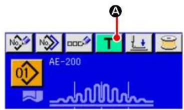
text_image
A No No DOC T AE-200 01① Select the target pattern number for teaching.
Select the pattern No. to be used for teaching on the pattern selection screen.
② Displaying the teaching screen.
When you press TEACHING button ( T A)
on the individual sewing editing screen (blue) or individual sewing screen (green), the teaching screen is displayed.
Because of the characteristics of the manipulator sensor, the sensor's detection status will be unstable if you turn ON the power to the sewing machine with a material placed on the sewing machine. To prevent the sensor from becoming unstable, carry out placement of the material as described below.

- Be sure to press the TEACHING button(A) for the first time after turning ON the power to the sewing machine with no material placed on the sensor.
- If LED blinks at a high speed or irregularly, remove the material from the sensor once. Then, re-place the material on the sensor to use the sewing machine.
23-1. Start teaching.
The teaching screen shown below is displayed. The backlight of the LCD display is green.
The number of stitches for all sections is 0 (zero).
Data on the upper/lower manipulator pressure value and the upper shirring amount which have already been recorded for the pattern selected for teaching are displayed.
The absolute value display and the percentage display can be changed over by selecting the shirring amount display. When you press the START button after having placed the material on the sewing machine,
the sewing machine head starts rotating and the number of stitches sewn in the relevant section is added. After the sensor detects the material end to allow the sewing machine to finish sewing, the number of stitches in the relevant section is cleared to "0" (zero).

text_image
A B 01 A D S042 0 3500 E S080 100 E S081 100 E S040 110 F H C J G U i M| Button and display Description | ||
| A | pattern No. display To be used to display the target pattern No. for teaching. | |
| B | Section name displayRIGHT/LEFT SCROLL buttons | To be used to display the target section for editing.The target section for editing can be selected by pressing these buttons. |
| C | PLUS buttonMINUS button | The sewing data value can be changed by pressing these buttons. |
| D | CANCEL button When you press this button, the teaching screen is closed and the screen returns to the individual sewing screen. | |
| E | SPEED VARIABLE RESISTOR The number of revolutions of the sewing machine can be changed with this variable resistor. | |
| F | ENTER button | When you press this button, the changed value in the sewing data list can be saved. Then, the teaching screen is closed and the screen returns to the individual sewing screen. |
| G | TEMPORARY STOP button The sewing machine can be stopped by pressing this button. | |
| H | SEWING DATA EDIT button | To be used to display the sewing data value.When you press this button, the sewing data input screen is displayed. |
| I | Sewing data number display To be used to display the sewing data number and pictographs. | |
| J | Sensor status display To be used to display the sensor status. | |
23-2. Finish teaching
When you press ENTER button (J F), thread trimming is carried out, the respective data are confirmed and the teaching is terminated. If the teaching is terminated though the material end sensor does not detect that the material has moved out of the sensor (teaching is terminated by stopping the sewing machine during sewing), the total number of stitches for sections [A] to [J] will be set for sewing parameter S010 (Stop after total number of stitches).
When you press CANCEL button (✗), the sewing machine terminates the teaching after performing thread trimming and discarding the setting you have made.
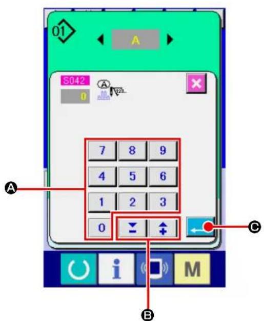
text_image
01 S042 7 8 9 4 5 6 1 2 3 0 B A C i M[Using the sewing data screen]
When you want to change the teaching sewing data value, input a desired value with the numeric keypad (A).
It is possible to change the input value for each editing unit using -/+ button (B).
When you press ENTER button (←), the teaching input data value is confirmed and the screen returns to the teaching screen.
24. Using check program
24-1. Displaying the check program screen

text_image
M 1 L2.3.. No No P Ver. APress key for three seconds, and CHECK PROGRAM button (A) is displayed on the screen. When this button is pressed down, the check program screen is displayed.
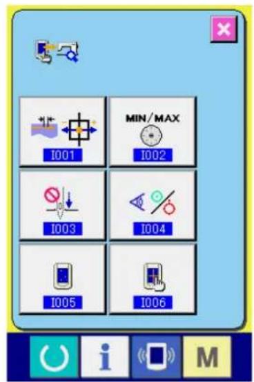
text_image
I001 MIN/MAX I002 I003 I004 I005 I006There are six check program items as described below.
Adjustment of the feed pitch
→ Refer to"VI-24-2. Adjusting the feed pitch" p.97.
Correction of the potentiometer for reading the bottom feed amount
→ Refer to"VI-24-3. Correcting the bottom feed amount readout potentiometer" p.98.
Main shaft motor belt replacement
→ Refer to "VI-24-4. Replacing the main shaft motor belt" p.99.
Sensor check
→ Refer to"VI-24-5. Performing sensor check" p.100.
LCD check
→ Refer to"VI-24-6.Performing LCD check" p.102.
Touch panel compensation
→ Refer to "VI-24-7. Performing touch panel compensation" p.103.
24-2. Adjusting the feed pitch

text_image
MIN/MAX I001 I002 I003 I004 I005 I006① Displaying the feed pitch adjustment screen.
When you press TOP FEED PITCH ADJUST-
MENT button (A) on the check program screen, the feed pitch adjustment screen is displayed.

text_image
1001 B C D i M② Adjusting the feed pitch.
Feed pitch adjustment range : -10 to 10
Initial value of the feed pitch adjustment : 0
It is possible to change the input value for each
editing unit with -/+ button ⏻ (B). If you
press CANCEL button (✗), the adjustment
value you have entered is discarded and the screen returns to the check program screen.
When you press ENTER button (← Ⓑ),
the feed pitch adjustment value is confirmed and the screen returns to the check program screen.
24-3. Correcting the bottom feed amount readout potentiometer
A potentiometer is used to read the bottom feed amount of the machine head. This potentiometer requires correction so as to compare its readout value with the actual feed amount.

text_image
I001 MIN/MAX I002 I003 I004 I005 I006 A① Displaying the bottom feed amount reading potentiometer correction screen.
When you press CORRECTION button

(A) for the bottom feed amount reading potentiometer on the check program screen, the correction screen for the top and bottom feed amount reading potentiometer is displayed.
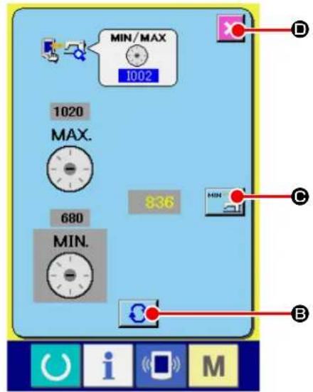
text_image
MIN/MAX 1002 1020 MAX. 680 MIN. 836 MIN B O U i S M② Correcting the bottom feed amount reading potentiometer.
Select [MIN] or [MAX] by pressing CHANGE-
OVER button

B).
* When "MIN" is selected : Pictograph of the COMMUNICATION button (C) : Set the feed amount to [0] (zero) by turning the BOTTOM FEED dial. Then, press COMMUNICATION button (C) to record the bottom feed amount.
* When "MAX" is selected :
Pictograph of the COMMUNICATION button (©) :

Set the feed amount to [4] by turning the BOT-TOM FEED dial. Then, press COMMUNICATION button (MIN) to record the bottom feed amount.
It is possible to exit from the setting screen by pressing CANCEL button ( )D).
24-4. Replacing the main shaft motor belt

text_image
I001 MIN/MAX I002 I003 I004 I005 I006 A① Displaying the main shaft motor belt replacement screen.
When you press MAIN SHAFT MOTOR BELT
REPLACEMENT button

(A) on the
check program screen, the main shaft motor belt replacement screen is displayed.

text_image
1003 B② Replacing the main shaft motor belt.
When you press CANCEL button ( ✗ B), the screen returns to the check program screen.
24-5. Performing sensor check
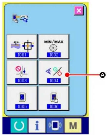
text_image
I001 MIN/MAX I002 I003 I004 I005 I006 A① Display the sensor check screen.
When SENSOR CHECK button ( A ) on the check program screen is pressed, the sensor check screen is displayed.
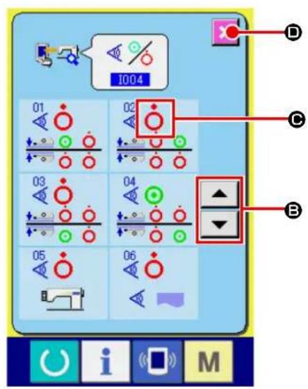
text_image
I004 01 02 C B 03 04 05 06 U i S M② Perform the sensor check screen.
Input status of the various sensors can be checked on the sensor check screen.
Input status of each sensor is displayed as ( C ). The display of ON status/OFF status is displayed as below.

: ON status

: OFF status
Press UP or DOWN button ( ▲ ▼ B) and display the sensor which has been checked.
When you press CANCEL button ( ✗, the screen returns to the check program screen.
14 kinds of sensors below are displayed.
| No. Pictograph Description of sensor | ||
 |  | Upper cloth inner (material end) sensor |
 | [5YXB] | Upper cloth outer sensor |
 | [H0GT] | Lower cloth inner (material end) sensor |
 |  | Lower cloth outer sensor |
 | [2H5Z] | Start switch |
 |  | Material detection sensor |
 |  | Top feed pitch origin sensor |
 |  | Machine head tilting switch |
| [ZW02] |  | SDET sensor |
| [DSWC] | [A036] | Starting pedal sensor 1 (Start) |
 | [HH3S] | Starting pedal sensor 2 (Presser foot) |
 |  | Starting pedal sensor 3 (Machine head speed changeover) |
 | [K40S] | Bobbin thread remaining amount detection, origin |
 | [20A8] | Bobbin thread remaining amount detection, no thread |
24-6. Performing LCD check
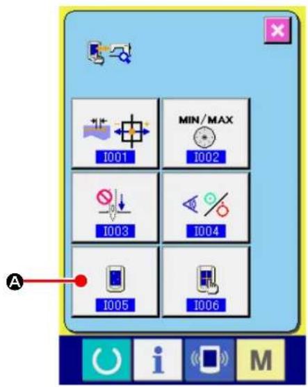
text_image
I001 MIN/MAX I002 I003 I004 I005 I006 A① Display the LCD check screen.
When LCD CHECK button ( [icon] A) on the check program screen is pressed, the LCD check screen is displayed.

text_image
Desktop screen with icons for power, info, app, and monitor on a blue background② Performing LCD check.
The screen of LCD check screen is displayed by one color only. Check in this state whether any dot is omitted or not.
After checking, press a proper place on the screen.
The LCD check screen is closed and the check program screen is displayed
24-7. Performing touch panel compensation

text_image
I001 MIN/MAX I002 I003 I004 I005 I006 A① Display the touch panel compensation screen.
When TOUCH PANEL COMPENSATION button

(A) on the check program screen is
pressed, the touch panel compensation screen is displayed.
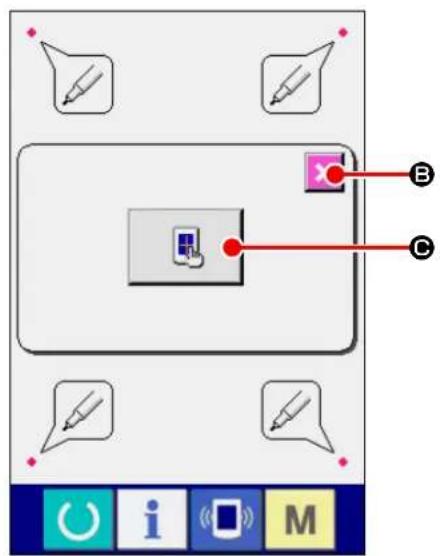
text_image
Screenshot of a software interface showing a toolbar with icons and labeled points A, B, C pointing to a device.② Pressing the TOUCH PANEL CORRECTION button.
If you want to start the correction of the touch panel, press TOUCH PANEL button (图标)
On that screen, the touch position can be checked. Press red dot on the screen. ON state/OFF state is displayed as shown below.

: OK state

: NG state
When you press CANCEL button ✗ (B), the screen returns to the previous screen.
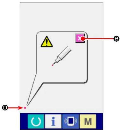
text_image
Diagram showing a speech bubble with warning symbols and labeled points A, B, D, likely illustrating a warning or error message.③ Press the lower left position.
Press red circle ( ◆ D) located at the lower left position on the screen.
When finishing the compensation, press CAN- CEL button ( C B ).
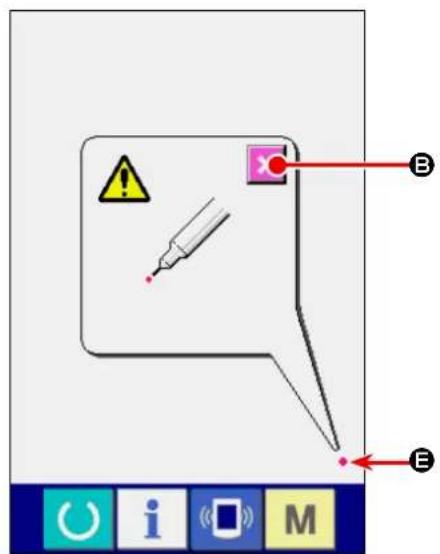
text_image
Diagram showing a warning icon with a syringe and labeled points B and E, alongside a toolbar with icons for O, i, M.④ Press the lower right position.
Press red circle ( ◆ E) located at the lower right position on the screen.
When finishing the compensation, press CAN- CEL button ( B ).

text_image
F B i M⑤ Press the upper left position.
Press red circle ( ◆ F) located at the upper left position on the screen.
When finishing the compensation, press CAN- CEL button ( C B ).
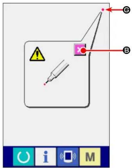
text_image
Diagram showing a warning symbol and labeled points (B, E) with a syringe and magnifying glass, likely from a software interface.⑥ Press the upper right position.
Press red circle ( ◆ G) located at the upper right position on the screen.
When finishing the compensation, press CAN- CEL button ( B ).
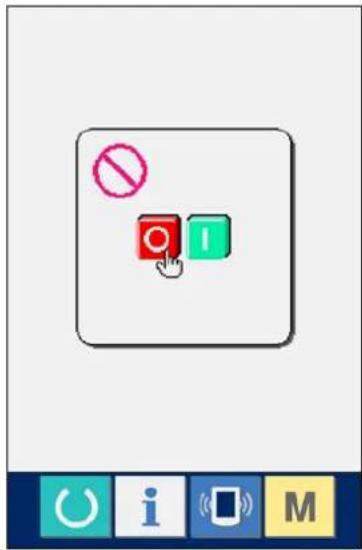
text_image
No I O i M⑦ Store the data.
When 4 points have been pressed, the screen showing power-OFF prohibition is displayed since the compensation data are to be stored.
Do not turn OFF the power while this screen is being displayed.
When the power is turned OFF, the compensated data are not stored.
When storing is finished, the check program screen is automatically displayed.
25. Error code list
| Error code | Description of error | How to recover | Place of recovery | |
| E001 |  | Notification of initialization of EEP-ROM on main control PCBNotifies that the EEP-ROM has been automatically initialized since no data was written on the EEP-ROM or the data written on it was broken | Turn OFF the power. | |
| E007 |  | Main shaft motor lockWhen the material which gives a high resistance to needle has been sewn | Turn OFF the power. | |
| E030 |  | Displacement of needle bar from upper positionWhen the needle fails to stop at its upper position even if you have tried to stop the sewing machine with its needle up at the startup of the sewing machine | Possible to re-enter after reset | Standard screen |
| E031 |  | Air pressure drop | Possible to re-enter after reset | |
| E050 |  | Stop switchWhen the stop switch has been pressed at the time of startup of the sewing machine | Possible to re-enter after reset | Standard screen |
| E052 |  | Thread breakage detectionWhen the needle thread has broken | Possible to re-enter after reset | |
| E061 |  | Memory switch data errorWhen the memory switch data is broken or revision update is necessary | Turn OFF the power. | |
| E062 |  | Sewing data errorWhen the sewing data is broken or revision update is necessary | Turn OFF the power. | |
| E072 |  | Motor lock error (during thread trimming) | Turn OFF the power. | |
| E302 |  | Machine head tilt confirmationWhen the machine head tilt sensor in the OFF state | Possible to re-enter after reset | Standard screen |
| E303 |  | Main shaft Z-phase sensor errorAbnormal Z-phase sensor for the encoder of the sewing machine motor | Turn OFF the power. | |
| E401 |  | When you have input the pattern No. that has already been registered | Possible to re-enter after reset | Copy destination pattern No. input screen |
| E402 |  | When you have tried to delete the pattern registered with cycle sewing | Possible to re-enter after reset | Pattern deletion screen |
| E403 |  | When you have input the pattern No. that has already been registered | Possible to re-enter after reset | New pattern No. registration screen |
| E404 |  | When you have tried to select an unregistered pattern | Possible to re-enter after reset | Pattern No. selection screen |
| E435 |  | When the set value exceeds the setting range | Possible to re-enter after reset | Data item input screen |
| E499 |  | Faulty setting of lower manipulator pressureWhen the bottom feed pitch is 2.5 mm or more, an error occurs if the lower manipulator pressure is set at 65 or less. | Possible to re-enter after reset | Standard screen |
| E703 |  | Operation panel connection to unexpected sewing machine (model error)When the model codes of the systems do not match during initial communication | Turn OFF the power. | |
| E704 | R-V-L | System version disagreementWhen the software versions of the systems software do not match during initial communication | Turn OFF the power. | |
| E730 |  | Malfunction or open-phase of main shaft motor encoderWhen the encoder of the sewing machine motor is abnormal | Turn OFF the power. | |
| E731 |  | Faulty main shaft motor hole sensor or position sensorWhen the hole sensor or the position sensor for the sewing machine motor is defective | Turn OFF the power. | |
| E733 |  | Main shaft motor reverse rotationWhen the sewing machine motor has rotated in the reverse direction | Turn OFF the power. | |
| E801 |  | Open-phase of power sourceWhen the input power source has an open phase | Turn OFF the power. | |
| E802 |  | Instantaneous power interruption detectionWhen the input power source has been interrupted instantaneously | Turn OFF the power. | |
| E811 |  | Over-voltageWhen the input power source voltage has increased to 280 V or more | Turn OFF the power. | |
| E813 |  | Low voltageWhen the input power source voltage has decreased to 150 V or less | Turn OFF the power. | |
| E901 |  | Abnormal main motor IPMWhen the IPM of servo-control PCB is abnormal | Turn OFF the power. | |
| E902 |  | Main shaft motor over-currentWhen an excessive current has flown in the sewing machine motor | Turn OFF the power. | |
| E903 |  | Abnormal stepping-motor power sourceWhen the power source of the stepping motor for servo control PCB fluctuates by ±15 % or more | Turn OFF the power. | |
| E904 |  | Abnormal solenoid power sourceWhen the power source of the solenoid for servo control PCB fluctuates by ±15 % or more | Turn OFF the power. | |
| E915 |  | Abnormal communication between operation panel and main CPUWhen difficulties in data communication have occurred | Turn OFF the power. | |
| E916 |  | Abnormal communication between main CPU and main shaft CPUWhen difficulties in data communication have occurred | Turn OFF the power. | |
| E943 |  | Faulty EEP-ROM on main control PCBWhen data cannot be written on the EEP-ROM | Turn OFF the power. | |
| E946 |  | Faulty writing on serial EEP-ROMWhen data cannot be written on the serial EEP-ROM | Possible to re-enter after reset | |
| E998 |  | Bobbin thread remaining amount detecting device origin error | Turn OFF the power. | |
| E999 |  | Upper shirring origin error | Possible to re-enter after reset |
26. Using communication function
The communication function is able to download the sewing data created with other sewing machines to you sewing machine. In addition, it is possible to upload the aforementioned data onto a memory medium or personal computer.
To enable communication, memory media and USB port are available.
* It should be noted that SU-1 (data server utility) is required to download/upload the data from/onto the personal computer.
26-1. Handling possible data
Handling possible sewing data are two kinds below. The respective data formats are as described below.
| Data name Extension Description of data | |||
| Parameter data AE00×××. | EPD  | Dedicated sewing data for the AE model created by the sewing machine | |
xxx : file NO.
If you want to save data to a memory medium, use the below-stated directory structure for saving. If the data file is not saved in the correct folder, the file cannot be read.

flowchart
graph TD
    A["Media drive"] --> B["AE200"]
    B --> C["AE00xxx.EPD"]
    B --> D["AE00xxx.EPD"]
    B --> E["AE00xxx.EPD"]
    B --> F["Save parameter data (AE only)"]
26-2. Performing communication by using the media
■ Memory medium insertion direction

① Turn the label side of the CompactFlash(TM) to this side (place the notch of the edge to the rear.) and insert the part that has a small hole into the panel.
② After completion of setting of the media, close the cover. By closing the cover, it is possible to access. If the media and the cover come in contact with each other and the cover is not closed, check the following matters.
- Check that the media is securely pressed until it goes no further.
- Check that the inserting direction of the media is proper.

- When the inserting direction is wrong, panel or media may be damaged.
- Do not insert any item other than the CompactFlash (TM).
- The media slot in the IP-420 accommodates to the CompactFlash (TM) of 2 GB or less.
The media slot in the IP-420 supports the FAT16 which is the format of the CompactFlash (TM). FAT32 is not supported.
- Be sure to use the CompactFlash (TM) which is formatted with IP-420. For the formatting procedure of the CompactFlash (TM), see "VI-26-4. Performing formatting of the media" p.115.
■ Method for removing a memory medium

text_image
Technical diagram showing a hand holding a device with labeled parts ① and ②, indicating a mechanical or electrical component assembly.① Hold the panel by hand, open the cover, and press the media ② removing lever ①. The media is eject.

When the lever ① is strongly pressed, the media ② may be broken by protruding and falling.
② When the media ② is drawn out as it is, removing is completed.
26-3. Carrying out communication with a USB thumb drive
■ Inserting a device into the USB port
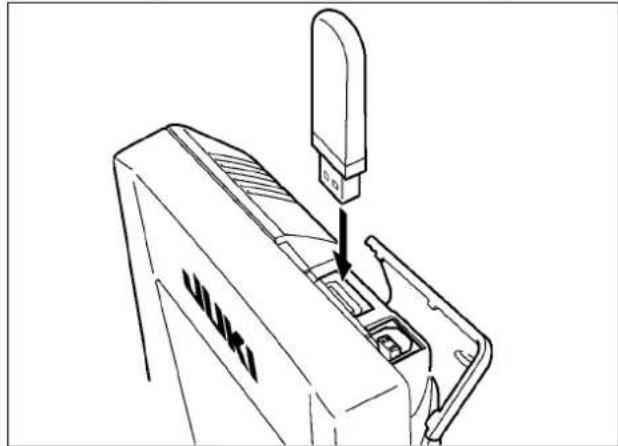
natural_image
Line drawing of a mechanical device with a downward arrow indicating a process or assembly (no text or symbols present)Slide the top cover and insert the USB device into the USB port. Then, copy data to be used from the USB device onto the main body.
After completion of copying the data, remove the USB device.
■ Disconnecting a device from the USB port
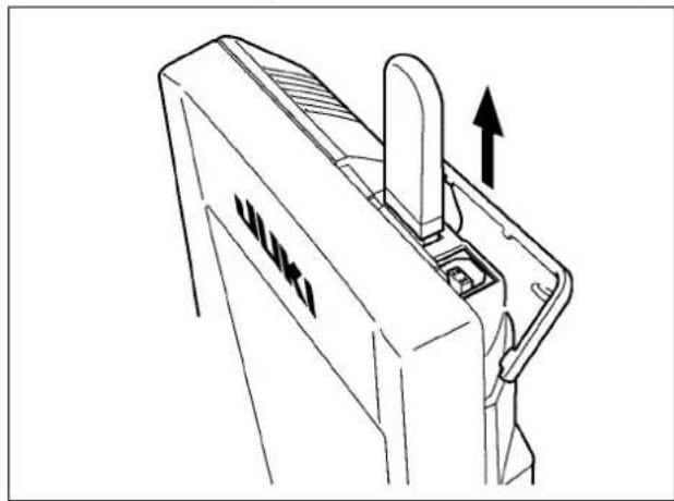
natural_image
Technical line drawing of a mechanical component with an upward arrow indicating motion (no text or symbols)Remove the USB device. Put the cover back in place.

Precautions for the use of CompactFlash (TM):
- Do not wet or touch it with wet hands. Fire or electric shock will be caused.
- Do not bend, or apply strong force or shock to it.
- Never perform disassembling or remodeling of it.
- Do not put the metal to the contact part of it. Data may be disappeared.
- Avoid storing or using it in the places below.
Place of high temperature or humidity / Place of dew condensation /
Place with much dust / Place where static electricity or electrical noise is likely to occur
① Precautions to be taken when handling USB devices
- Do not leave the USB device or USB cable connected to the USB port while the sewing machine is in operation. The machine vibration can damage the port section resulting in loss of data stored on the USB device or breakage of the USB device or sewing machine.
- Do not insert/remove a USB device during reading/writing a program or sewing data.
It may cause data breakage or malfunction.
- When the storage space of a USB device is partitioned, only one partition is accessible.
- Some type of the USB device may not be properly recognized by this sewing machine.
- JUKI does not compensate for loss of data stored on the USB device caused by using it with this sewing machine.
- When the panel displays the communication screen or pattern data list, the USB drive is not recognized even if you insert a medium into the slot.
- For USB devices and media such as CF cards, only one device/medium should be basically connected/inserted to/into the sewing machine. When two or more devices/media are connected/inserted, the machine will only recognize one of them. Refer to the USB specifications.
- Insert the USB connector into the USB terminal on the IP panel until it will go no further.
- Do not turn the power OFF while the data on the USB flash drive is being accessed.
② USB specifications
- Conform to USB 1.1 standard
- Applicable devices * 1____ Storage devices such as USB memory, USB hub, FDD and card reader
- Not-applicable devices__CD drive, DVD drive, MO drive, tape drive, etc.
- Format supported ____FD (floppy disk) FAT 12 Others (USB memory, etc.), FAT 12, FAT 16, FAT 32
- Applicable medium size_FD (floppy disk) 1.44MB, 720kB Others (USB memory, etc.), 4.1MB \~ (2TB)
- Recognition of drives __For external devices such as a USB device, the device which is recognized first is accessed. However, when a medium is connected to the built-in media slot, the access to that medium will be given the highest priority. (Example: If a medium is inserted into the media slot even when the USB memory has already been connected to the USB port, the medium will be accessed.)
- Restriction on connection _ Max. 10 devices (When the number of storage devices connected to the sewing machine has exceeded the maximum number, the 11th storage device and beyond will not be recognized unless they are once disconnected and re-connected.)
- Consumption current ____The rated consumption current of the applicable USB devices is 500 mA at the maximum.
*1: JUKI does not guarantee operation of all applicable devices. Some device may not operate due to a compatibility problem.
26-4. Performing formatting of the media
To re-format a medium, the IP-420 has to be used. The IP-420 is not able to read any medium which is formatted on a personal computer.

text_image
M 1 1.2.3.. No No P Ver A i M① Display the media format screen.
When key is held pressed for three
seconds, MEDIA FORMAT button → (A) is displayed on the screen. When this button is pressed, the media format screen is displayed

text_image
M542 Formatting is performed. OK ? B② Start formatting of the media.
Set the media you desire to format to the media slot, close the cover, press ENTER button (B) and formatting starts. Save necessary data in the media to the other media before formatting. When formatting is performed, the inside data are deleted.
When two or more media are connected to the sewing machine, the medium to be formatted is determined by the predetermined priority order.
High ← Low

CF(TM) slot ← USB device 1 ← USB device 2 ← ....
When a CompactFlash (TM) is inserted in the CF(TM) slot, the CompactFlash (TM) will be formatted according to the priority order as shown above.
Refer to the USB specifications for the priority order of access.
[Prohibitions concerning handling of the electronic medium]
① The memory medium is a precision electronic device. Do not bend or give an impact to the memory medium.
② It is recommended to periodically store the data you have saved to a memory medium on other memory medium as security against accidents.
③ If you want to initialize the data, firstly make sure that the memory card does not contain any necessary data. If the memory card is initialized, the data stored on the memory card will be totally erased.
④ Avoid the use and storage of memory media in a hot and humid place.
⑤ Avoid the use of memory media near heat generating and/or combustible materials.
⑥ If contact parts of a memory medium are stained, contact failures will be caused. To avoid contact failures, do not touch them with hands. In addition, keep the contact parts clean by protecting them against dirt, dust, oil and other foreign matters. Carefully handle memory media also to protect against static electricity, etc. since static electricity can destroy internal elements.
⑦ Memory media have a limited life. After a long time of use, writing or deletion failures will occur. If such a phenomenon occurs, replace the memory medium with a new one.
26-5. Take-in of the data

flowchart
graph TD
    A["Device 001"] --> B["Network Component 11"]
    C["No EPD"] --> B
    D["Interface Icon"] --> B
    E["Device 11"] --> B
    F["Device 001"] --> G["Network Component 11"]
    H["Device 11"] --> G
    I["Interface Icon"] --> J["Network Component 11"]
    K["Device 001"] --> L["Network Component 11"]
    M["Device 11"] --> L
    N["Interface Icon"] --> O["Network Component 11"]
    P["Device 001"] --> Q["Network Component 11"]
    R["Device 11"] --> Q
    S["Interface Icon"] --> T["Network Component 11"]
    U["Device 001"] --> V["Network Component 11"]
    W["Device 11"] --> V
    X["Interface Icon"] --> Y["Network Component 11"]
    Z["Device 001"] --> AA["Network Component 11"]
    AB["Device 11"] --> AA
    AC["Interface Icon"] --> AD["Network Component 11"]
    AE["Device 001"] --> AF["Network Component 11"]
    AG["Device 11"] --> AF
    AH["Interface Icon"] --> AI["Network Component 11"]
    AJ["Device 001"] --> AK["Network Component 11"]
    AL["Device 11"] --> AK
    AM["Interface Icon"] --> AN["Network Component 11"]
    AO["Device 001"] --> AP["Network Component 11"]
    AQ["Device 11"] --> AP
    AR["Interface Icon"] --> AS["Network Component 11"]
    AT["Device 001"] --> AU["Network Component 11"]
    AV["Device 11"] --> AU
    AW["Interface Icon"] --> AX["Network Component 11"]
    AY["Data Icon"] --> AZ["A"]
① Display the communication screen.
When communication key ( A ) of switch seat part is pressed in the data input screen, the communication screen is displayed.
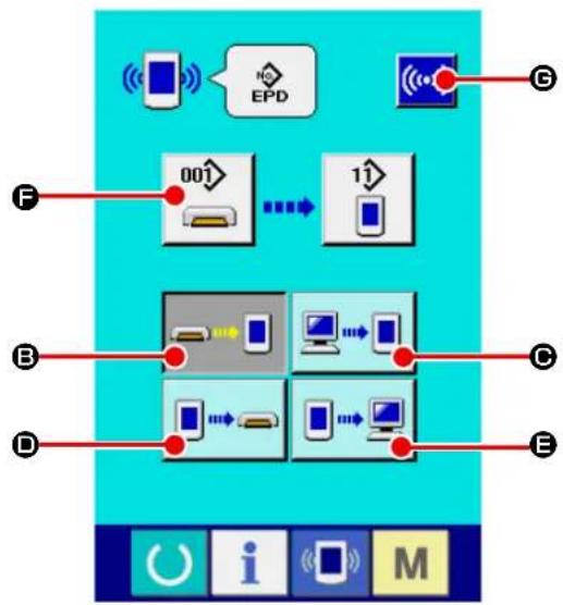
flowchart
graph TD
    A["Smart Phone"] --> B["EPD"]
    B --> C["Network"]
    D["Device 001"] --> E["Mobile Device"]
    E --> F["11"]
    G["Device 1"] --> H["Mobile Device"]
    H --> I["11"]
    J["Device 2"] --> K["Mobile Device"]
    K --> L["11"]
    M["Device 3"] --> N["Mobile Device"]
    N --> O["11"]
    P["Device 4"] --> Q["Mobile Device"]
    Q --> R["11"]
    S["Device 5"] --> T["Mobile Device"]
    T --> U["11"]
② Select the communication procedure.
There are four communication procedures as described below.
(B) Writing data from media to panel
(C) Writing data from personal computer (server) to panel
(D) Writing data from panel to media
(E) Writing data from panel to personal computer (server)
Select the button of communication procedure you desire.

text_image
EPD 7 8 9 4 5 6 1 2 3 0 +③ Select the data No.
When you press ( 🔍 F ), the writing file selection screen is displayed.
Input the file number of the data you want to write. Input the numerical digits corresponding to the "xxx" portion of the file name "AE00***. EPD".
It is also possible to specify the pattern No. to be written in the destination medium. If you want to write data on the operation panel, an unregistered pattern No. will be displayed.
④ Determine the data No.
When ENTER button (←→) is pressed, the data No. selection screen is closed and the selection of the data No. has been completed.

text_image
M670 Data is being written.⑤ Start communication.
When COMMUNICATION START button

(©) is pressed, the data communication starts.

Do not open the cover during reading the data. Data may not be read in.
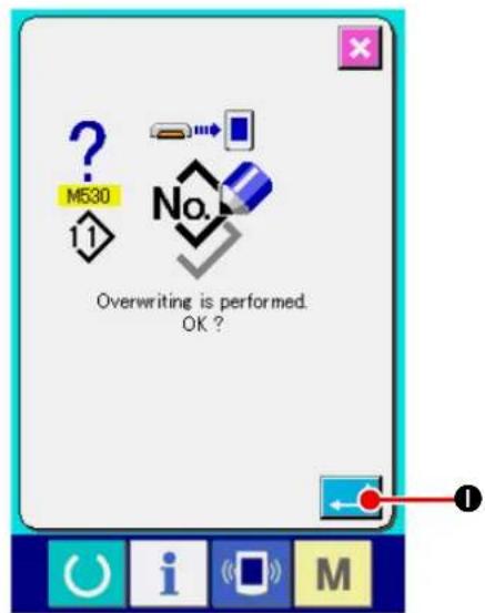
text_image
? M530 11 No. Overwriting is performed. OK?* If you want to write data on the existing pattern No., the overwrite confirmation screen will be displayed before executing writing. If you want to overwrite the existing pattern No., press ENTER button (●).
27. Information function
There are three functions below in the information function.
- Oil replacement time, needle replacement time, cleaning time, etc. are designated and the warning notice is performed when the designated time has passed.
→ Refer to and "VI-27-1. Observing the maintenance and inspection information" p.121. and "VI-27-2. Inputting the inspection time" p.124. - Speed can be checked at a glance and the target achieving consciousness as a line or group is increased as well by the function to display the target output and the actual output.
→ Refer to and "VI-27-4. Observing the production control information" p.126. and "VI-27-5. Performing setting of the production control information" p.129. - Information on machine working ratio, pitch time, machine time and machine speed can be displayed from the working state of the sewing machine.
→ Refer to and "VI-27-6. Observing the working measurement information" p.132.
27-1. Observing the maintenance and inspection information
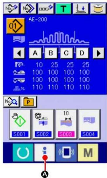
text_image
AE-200 10 25 25 25 100 100 100 100 100 100 100 100 110 110 110 110 S001 S002 S003 S004 A① Display the information screen.
When you press INFORMATION key ( i A)
displayed on the switch seat part of the data input screen, the information screen is displayed.

text_image
i B② Display the maintenance and inspection information screen.
Press maintenance and inspection information screen display button 📋) in the information screen.
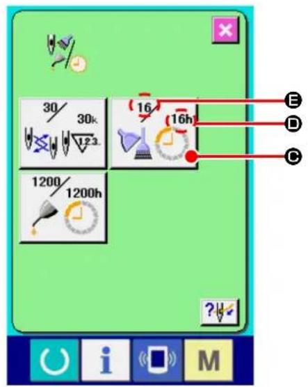
text_image
30/ 30k 123 16 16h 1200/ 1200h E D C ?Information on the following three items is displayed in the maintenance and inspection information screen.
- Needle replacement :

(1,000 stitches)
- Cleaning time (hour) :

- Oil replacement time (hour) :

The interval to inform of the inspection for each item in button (C) is displayed at (D), and remaining time up to the replacement is displayed at (E). In addition, remaining time up to the replacement can be cleared.
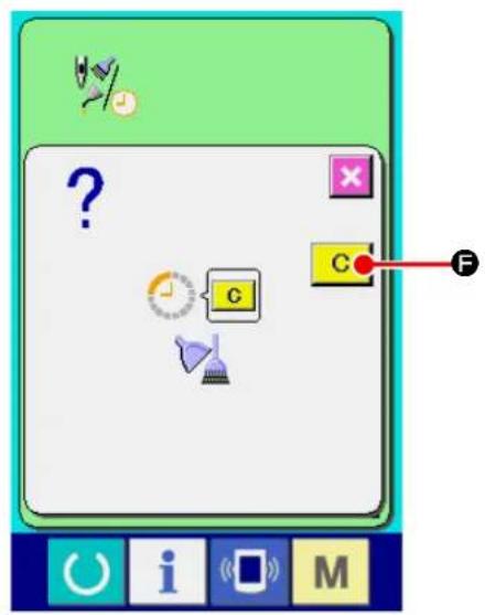
text_image
Game interface screenshot showing a character input with icons and a labeled button C, marked with letter F.③ Perform clearing remaining time up to the replacement.
When you press the ITEM button ( C) you want to clear, the replacement clear screen is displayed. When you press CLEAR button C (F), the remaining time before replacement is cleared.
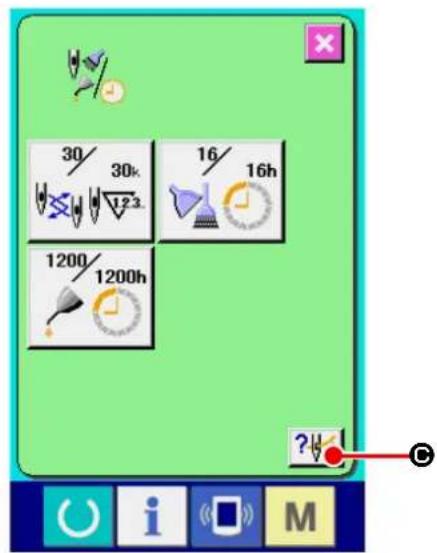
text_image
30/ 30k 123 16/ 16h 1200/ 1200h ?④ Display the threading diagram.
When threading button ( ? ) displayed in the maintenance and inspection screen is pressed, the needle thread threading diagram is displayed. Observe it when performing threading.

text_image
Technical diagram of a sewing machine with labeled parts and directional arrows indicating motion or operation27-2. Inputting the inspection time
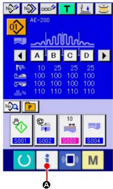
text_image
AE-200 10 25 25 25 100 100 100 100 100 100 100 100 110 110 110 110 S001 S002 S003 S004 A M
text_image
Screenshot of a software interface with icons and labeled point B, likely from an older application or tool set.① Display the information screen (maintenance personnel level).
When you keep INFORMATION key ( i A)
displayed on the switch seat part of the data input screen held pressed for approximately three seconds, the information screen (maintenance personnel level) is displayed. In the maintenance personnel level, the color of the pictograph displayed at the upper left on the screen changes from blue to orange. In addition, five buttons are displayed.
② Display the maintenance and inspection information screen.
Press maintenance and inspection information screen display button (B) in the information screen.
* Refer to "VI-31. Information screen of the maintenance personnel level" p.142 for the two buttons displayed on the lower column of the screen.

text_image
30/ 30k 123. 16/ 16h 1200/ 1200h ?The same information as that in the normal maintenance and inspection information screen is displayed in the maintenance and inspection information screen.
When button (16 10b) of the item you desire to change the inspection time is pressed, the inspection time input screen is displayed.
③ Input the inspection time.
Input an inspection time.
When the inspection time is set to "0", the warning function stops.
When clear button ( C D) is pressed, the value returns to the initial value.
The initial values of the inspection time of respective items are as follows.
- Needle replacement : 0 (1,000 stitches)
· Cleaning time : 0 (hour)
· Oil replacement time : 200 (hour)
When ENTER button ( ← Ⓑ) is pressed, the inputted value is determined.
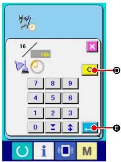
text_image
16 16h 7 8 9 4 5 6 1 2 3 0 C D E27-3. Releasing procedure of the warning

text_image
Game interface screenshot showing a character input with question mark, clock, and function buttons labeled G, C, F, and O, i, M.When the designated inspection time is reached, the warning screen is displayed.
In case of clearing the inspection time, press CLEAR button (C F). The inspection time is cleared and the pop-up is closed. In case of not clearing the inspection time, press CANCEL button (X G) and close the pop-up. Every time one sewing is completed, the warning screen is displayed until the inspection time is cleared.
Warning Nos. of the respective items are as follows.
It is possible to designate the start, display the number of pieces of production from the start to the existing time, display the number of pieces of production target, etc. in the production control screen.
There are two kinds of display ways for the production control screen.
27-4-1. When displaying from the information screen

text_image
AE-200 10 25 25 25 100 100 100 100 100 100 100 100 110 110 110 110 S001 S002 S003 S004 A i M① Display the information screen.
When you press INFORMATION key ( i A)
displayed on the switch seat part of the data input screen, the information screen is displayed.

text_image
i B② Display the production control screen.
Press production control screen display button

(B) in the information screen. The pro-
duction control screen is displayed.
Information on the following 5 items is displayed in the production control screen.
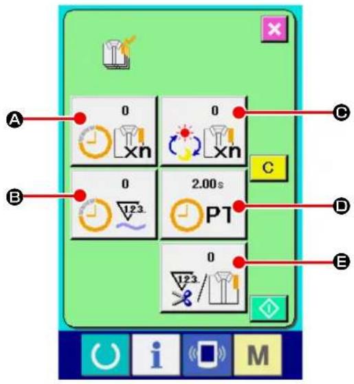
text_image
A 0 0 C B 0 2.00s C D E 123 P1 0 123/123/123/123A : Existing target value
Number of pieces of the target of products at the present time is automatically displayed.
B: Actual results value
Number of pieces of the sewn products is automatically displayed.
©: Final target value
Number of pieces of the final target of products is displayed.
Input the number of pieces referring to "VI-27-5. Performing setting of the production control information" p.129.
☐ : Pitch time
Time (second) required for one process is displayed.
Input the time (unit : second) referring to "VI-27-5. Performing setting of the production control information" p.129.
E : Number of times of thread trimming
Number of times of thread trimming per process is displayed.
Input the number of times referring to "VI-27-5. Performing setting of the production control information" p.129.
27-4-2. When displaying from the sewing screen

text_image
S001 S002 S003 S004 A① Displaying the sewing screen.
When press READY key ( Ⓗ A) on the switch seat part of the data input screen, the sewing screen is displayed.
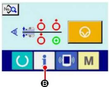
text_image
Diagram showing a control interface with icons for signal processing, display, and function buttons labeled O, i, M, and B.② isplay the production control screen.
When you press INFORMATION key ( i ⑧)
on the switch seat part of the sewing screen, the product management screen is displayed.

text_image
0 xn 0 2.00s PT 0 i MThe contents of display and the functions are common to "VI-27-4-1. When displaying from the information screen" p.126.
27-5. Performing setting of the production control information

text_image
A 0 0 C B 0 2.00s C D E 0 1/23/ 1/23/ i M① Display the production control screen.
Display the production control screen referring to "VI-27-4. Observing the production control information" p.126.
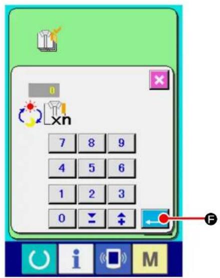
text_image
0 xn 7 8 9 4 5 6 1 2 3 0 F② Input the final target value.
Firstly, input the production target number of pieces for the process you want to carry out sewing. When you press FINAL TARGET VAL-

©), the final target value
input screen is displayed. Input a desired value with the numeric keypad or the UP/DOWN buttons. After you have completed input of the target value, press ENTER button ( )
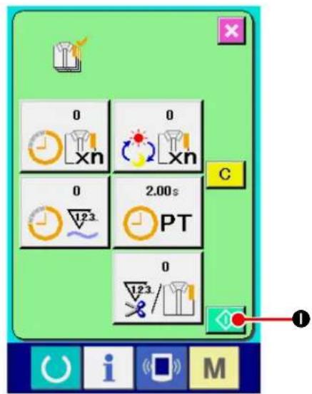
text_image
0 xn 0 2.00s PT 0 1/23/1/23 C I M③ Start the count of number of pieces of production.
When START button ( ◇ ①) is pressed, the count of number of pieces of production is started.
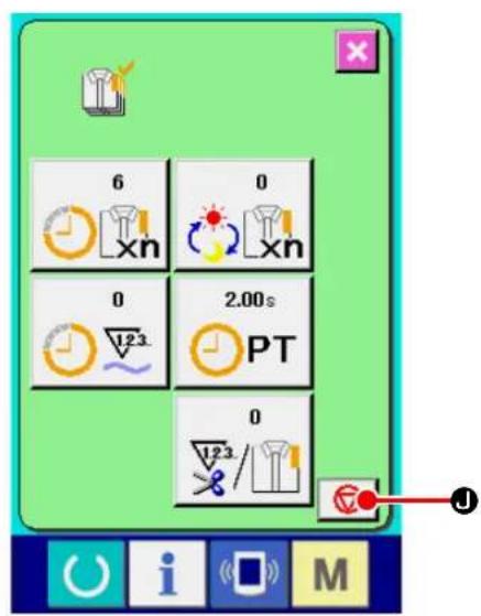
text_image
6 0 0 2.00s PT 0④ Stop the count.
Display the production control screen referring to "VI-27-4. Observing the production control information" p.126.
When the count is being performed, STOP button (i) is displayed. When STOP button (ii) is pressed, the count is stopped.
After the stop, START button is displayed at the position of STOP button. When continuing the count, press START button again. The counted value is not cleared until CLEAR button is pressed.

text_image
0 xn 0 xn 0 2.00s PT 0 123/ L M C K⑤ Clear the counted value.
When clearing the counted value, set the count to the stop state and press CLEAR button C (K).
The value to be cleared is the present target value (L) and actual results value (M) only.
( Note : CLEAR button is displayed only in case of stop state. )
When CLEAR button ( C K) is pressed, the clear confirmation screen is displayed.

text_image
Game interface screenshot showing a checklist with a question mark, a checkmark, and a highlighted 'C' button labeled 'N'When CLEAR button ( C N) is pressed in the clear confirmation screen, the counted value is cleared.
27-6. Observing the working measurement information

text_image
AE-200 10 25 25 25 100 100 100 100 100 100 100 100 110 110 110 110 S001 S002 S003 S004 A i M① Display the information screen.
When you press INFORMATION key ( i A)
displayed on the switch seat part of the data input screen, the information screen is displayed.
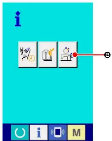
text_image
i B C i M② Display the working measurement screen.
Press working measurement screen display
button (B) in the information screen. The working measurement screen is displayed.

text_image
0.00% 0sti/min 0.00s 0.00s PT MT 0 A B C D E
text_image
0 7 8 9 4 5 6 1 2 3 0 ← ↑ FInformation on the following 5 items are displayed in the working measurement screen.
A: The information is automatically displayed from the time of start of measuring the working ratio.
B: The information is automatically displayed from the time of start of measuring the machine speed.
C: The information is automatically displayed from the time of start of measuring the pitch time.
D: The information is automatically displayed from the time of start of measuring the machine time.
E : Number of times of thread trimming is displayed.
Input the number of times referring to the next
③
③ Input the number of times of thread trimming.
In the next step, input the number of times of thread trimming for one process.
When you press NUMBER OF TIMES OF
THREAD TRIMMING button

E) dis-
played on the previous page, the number of times of thread trimming input screen is displayed.
Input a desired value with the numeric keypad or the UP/DOWN buttons. After you have completed input of the desired value, press ENTER button (↓ F).
* When the input value is 0, count of the number of times of thread trimming is not performed. Use this function by connecting the external switch.
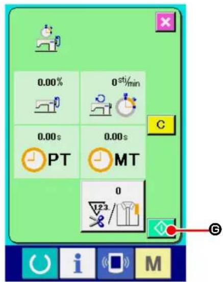
text_image
0.00% 0 sti/min 0.00s 0.00s PT MT 0 123 G④ Start the measurement.
When START button ( ◆ ©) is pressed, measurement of each data is started.
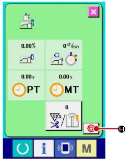
text_image
0.00% 0 sti/min 0.00s 0.00s PT MT 0 123 H i M⑤ Stop the count.
Display the working measurement screen referring to ① and ② of "VI-27-6. Observing the working measurement information" p.132.
STOP button ( □ H) is displayed when the measurement is being performed. When STOP button ( □ H) is pressed, the measurement is stopped.
After the stop, START button is displayed at the position of STOP button. To continue measuring, press START button again. The measured value is not cleared until CLEAR button is pressed.

text_image
0.00% 0sti/min 0.00s 0.00s PT MT 0 123 i M⑥ Clear the counted value.
When clearing the counted value, set the count to the stop state and press CLEAR button C (①).
( Note : CLEAR button is displayed in case of the stop state only. )
When CLEAR button ( C ①) is pressed, the clear confirmation screen is displayed.

text_image
Screenshot of a simple computer interface with icons, a question mark, and a labeled button 'C' pointing to it.When CLEAR button ( C ⓚ) is pressed in the clear confirmation screen, the counted value is cleared.
28. Performing keylock

text_image
M 1 I2.3.. No Ver A① Display the key lock screen.
When you keep key held pressed for
three seconds, KEYLOCK button

A) is
displayed on the screen.
When you press this button, the keylock screen is displayed. The current keylock setting state is displayed on the button.
: The state where keylock is not set
: The state where keylock is set
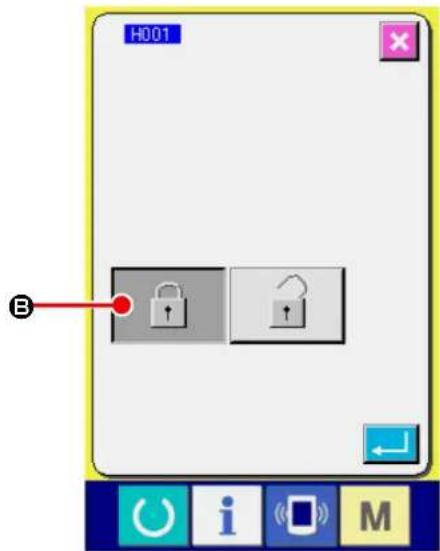
text_image
H001 B② Select and determine the key lock state.
Select the key lock state button ( 🔍 Ⓑ) in the
key lock setting screen, and press . Then the key lock setting screen is closed and the key lock state is set.
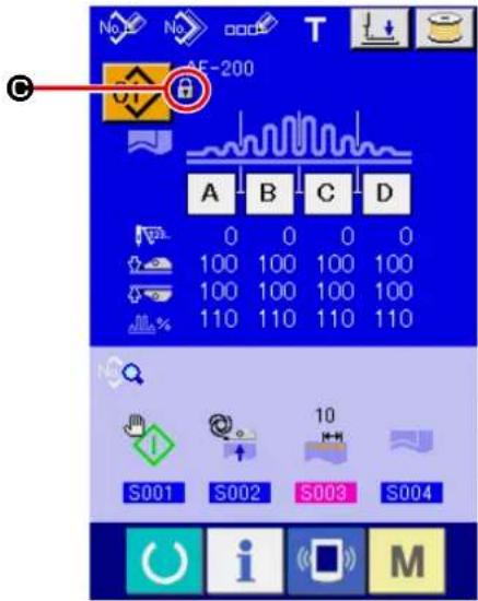
text_image
No No OOO T AE-200 A B C D 0 0 0 0 100 100 100 100 100 100 100 100 110 110 110 110 S001 S002 S003 S004 i M③ Closing the mode screen to display the data input screen.
When you close the mode screen to display the data input screen, the pictograph (©) that indicates the keylock status is displayed on the right side of the pattern No. display. In addition, the buttons that can be used even under the keylock state are displayed.
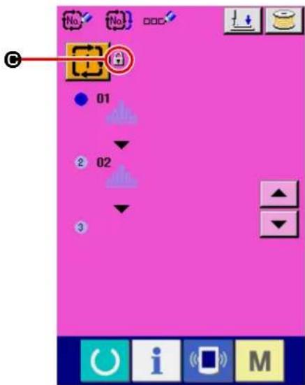
text_image
No No 01 2 02 329. Displaying version information

text_image
M 1 12.3.. No No P Ver A① Displaying the version information display screen.
When you keep key held pressed for three seconds, VERSION INFORMATION DISPLAY button (A) is displayed on the screen. When you press this button, the version information screen is displayed.
On the version information screen, the version information on your sewing machine is displayed to allow you to confirm it.
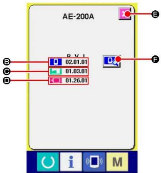
text_image
AE-200A B V I 02.01.01 01.03.01 01.26.01 B C D F O i MB : Version information on panel program
© : Version information on main program
☐ : Version information on servo program
When CANCEL button ( ✗ E) is pressed, the version information screen is closed and the mode screen is displayed.

text_image
MODULE R.V.L SUM IPMAINPRGM 02.01.01-00 DCA2 IPMAINIMG 02.01.01- B00D IPMAINLANIMG1 02.01.01- C7DF IPMAINLANIMG2 02.01.01- 1EB3 IPL 01.01.07-00 _______________________________ _______________________________ _______________________________ _______________________________ _______________________________ _______________________________ _______________________________ _______________________________ _______________________________ _______________________________ _______________________________ _______________________________ _______________________________ _______________________________ _______________________________ _______________________________ _______________________________ _______________________________ _______________________________ _______________________________ _______________________________ _______________________________ _______________________________ _______________________________ _______________________________ ______________________________① Displaying the operation panel program version details screen.
When you press OPERATION PANEL VER-
SION DETAILS button 📄, the operation panel version details screen is displayed.
On the operation panel version details screen, details of the operation panel program version are displayed to allow you to confirm them.
When you press CANCEL button ( ✗ Ⓑ), the operation panel version details screen is closed and the screen returns to the version information screen.
30. Communication screen of maintenance personnel level
For the communication screen, the level which is normally used and the one which is used by the maintenance personnel are different in the kinds of data to be handled.
30-1. Data which are possible to be handled
In case of the maintenance personnel level, it is possible to use 5 different kinds of data in addition to the normal two kinds.
| Data name Extension Description of data | |||
| Adjustment data |  | Model name+00×××.MSWExample) AE00001.MSW | Data of memory switches 1 and 2 |
| All sewing machine data |  | Model name+00×××.MSPExample) AE00001.MSP | All data which are held by sewing machine |
| Panel program data(*) |  | Folder BP+RVL (6 digits)(5 files) | Program data and display data of panel |
Main program data(*) MA+RVL(  PRG Program data of main PRG Program data of main | |||
Servo program data(*) MT+RVL  .PRG Program data of servo .PRG Program data of servo | |||
xxx: File No.
* Refer to the Setup Manual for the IP-420 for the operation panel program data, main program data and servo program data.
30-2. Displaying maintenance personnel level
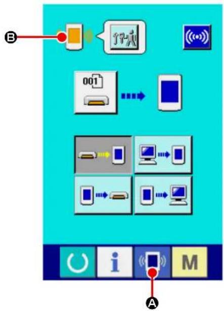
flowchart
graph TD
    A["Input Data"] --> B["Device 001"]
    B --> C["Device 002"]
    C --> D["Device 003"]
    D --> E["Output"]
    style A fill:#f9f,stroke:#333
    style E fill:#bbf,stroke:#333
① Display the communication screen of the maintenance personnel level.
When key (A) is pressed as long as three seconds, the image located at the upper left position is changed to orange color (B) and the communication screen of the maintenance personnel level is displayed.
For the operating procedure, refer to "VI-26-5. Take-in of the data" p.117.

flowchart
graph TD
    A["Mobile Device"] -->|Data| B["001 Interface"]
    C["Smartphone"] -->|Data| B
    D["Computer"] -->|Data| B
    E["Desktop Computer"] -->|Data| B
    F["Mobile Device"] -->|Data| B
    G["Desktop Computer"] -->|Data| B
    H["Desktop Computer"] -->|Data| B
* If you have selected the adjustment data or all sewing machine data, the display on the screen will be as shown in the figure on the left. In this case, it is not necessary to specify the number on the operation panel side.
31. Information screen of the maintenance personnel level
31-1. Display of error record
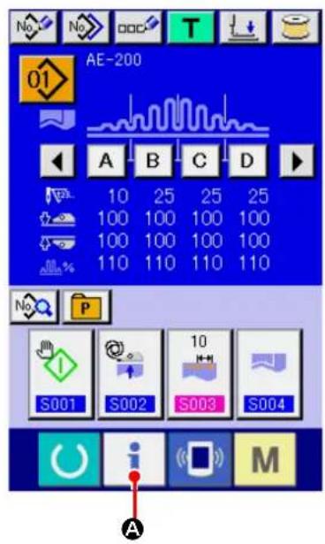
text_image
AE-200 10 25 25 25 100 100 100 100 100 100 100 100 110 110 110 110 S001 S002 S003 S004 A i M① Display the information screen of the maintenance personnel level.
When INFORMATION key ( i A) of switch
seat part is pressed for approximately three seconds in the data input screen, the information screen of the maintenance personnel level is displayed. In case of the maintenance personnel level, the pictograph located at the upper left position changes from blue color to orange color, and 5 buttons are displayed.
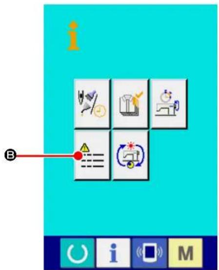
text_image
i B② Displaying the error history screen.
Press ERROR HISTORY SCREEN DISPLAY
button ⬆) on the information screen.
Then, the error history screen is displayed.

text_image
20 E11 428 19 E915 385 18 E916 342 17 E917 299 16 E918 257 15 E943 214 14 E946 171 G E AError record of the sewing machine you use is displayed in the error record screen, and you can check the error.
© : Order that error has occurred
D : Error code
E : Cumulative current-carrying time (hour) at the time of occurrence of error
When CANCEL button (K) is pressed, the error record screen is closed and the information screen is displayed.
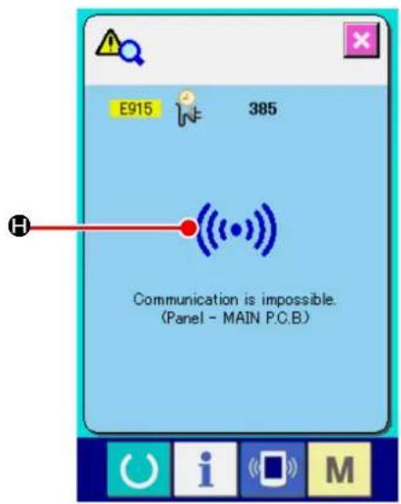
text_image
E915 385 H Communication is impossible. (Panel - MAIN P.C.B.)③ Display the error record screen.
When you desire to know the details of error, press ERROR button (19 E915 385 F) you desire to know. The error detail screen is displayed.
Pictograph ( H) corresponding to the error code is displayed in the error detail screen.
→ Refer to "VI-25. Error code list" p.107.
31-2. Display of the cumulative working information
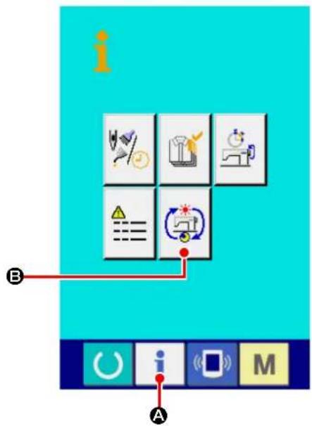
text_image
Screenshot of a software interface with labeled icons and labels A and B, showing icons for data analysis, optimization, and system control.① Display the information screen of the maintenance personnel level.
When INFORMATION key ( i A) of switch seat part is pressed for approximately three seconds in the data input screen, the information screen of the maintenance personnel level is displayed. In case of the maintenance personnel level, the pictograph located at the upper left position changes from blue color to orange color, and 5 buttons are displayed.
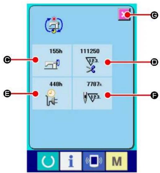
text_image
155h 111250 448h 7787k 12.3. 12.3. E G D F i M② Display the cumulative working information screen.
Press CUMULATIVE WORKING INFORMA-
TION SCREEN DISPLAY button (B) of
the information screen. The cumulative working information screen is displayed.
Information on the following 4 items are displayed in the cumulative working information screen.
● : Cumulative working time (hour) of the sewing machine is displayed.
D : Number of cumulative times of thread trimming is displayed.
E : Cumulative current-carrying time (hour) of the sewing machine is displayed.
F : Number of cumulative stitches is displayed.
(Unit : X1,000 stitches)
When CANCEL button ( ✗ Ⓔ) is pressed, the cumulative working information screen is closed and the information screen is displayed.
VII. HANDLING AND ADJUSTING THE PARTS
1. Adjusting the material slippage and manipulator pressure
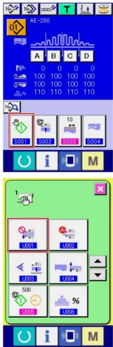
text_image
AE-200 A B C D 0 0 0 0 100 100 100 100 100 100 100 100 110 110 110 110 S001 S002 S003 S004 i M U001 U002 U003 U004 500 U005 % U006 i M① Displaying the data input screen.
The set contents can be changed only on the data input screen (blue). In the case the sewing screen (green) is displayed, press READY key

to display the data input screen.
② Setting the start mode to the manual mode.
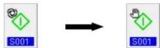
(Set the start mode referring to "VI-10. Changing sewing data" p.57.)
③ Stopping the manipulator operation.

(Set the manipulators referring to "VI-19. Changing the memory switch data" p.85.)
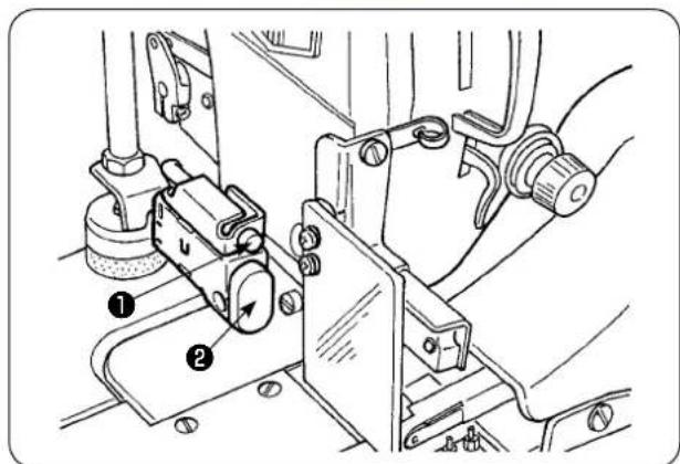
text_image
Technical diagram of a mechanical assembly with numbered components, likely for assembly or maintenance instructions.④ Displaying the sewing screen.
When you press the READY key on the data input screen, the sewing screen is displayed, the presser foot of the sewing machine goes up and LED ① flashes on and off.
⑤ Rotate upper manipulator ③ to enable adjustment without the manipulator.
After having adjusting the bottom feed length (refer to "IV-10. Adjusting the stitch length" p.12 for the adjusting procedure), place two plies of material ④ for trial stitching which have been cut into same dimensions under the presser foot of the sewing machine. Press START switch ② to start the sewing machine. Continue sewing until material end ⑤ is reached. Then, re-press START switch ② to stop the sewing machine.
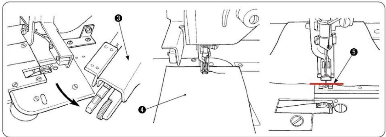
text_image
Technical diagram of sewing machine components with numbered parts and directional arrows indicating assembly steps
text_image
Diagram showing two labeled parts (A and B) with arrows pointing to different surface behaviors or materials.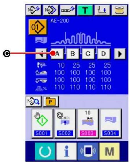
text_image
No. No. T AE-200 01 A B C D 10 25 25 25 100 100 100 100 100 100 100 100 110 110 110 110 S001 S002 S003 S004 No. P M i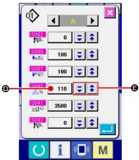
text_image
S082 0 S080 100 S081 100 S040 110 S041 3500 S042 0⑥ Adjust the shirring amount in accordance with the slippage between the two plies of material after trial stitching.
In the case of ( A ), select the sewing parameter [S40] "section A-shirring amount." Decrease the shirring amount.
In the case of ( B ), select the sewing parameter [S40] "section A-shirring amount." Increase the shirring amount.
⑦ Operation for changing the shirring amount
When you press SECTION A button (A Ⓒ)
on the data input screen, the sewing data change screen is displayed.
Change the percentage value ( D) in shirring
section A data field with -/+ button
(①). Then, carry out trial stitching
again by pressing READY key to adjust the slippage between two plies of material. Repeat trial stitching and adjustment until the ends of the two plies of material are aligned.
⑧ Adjusting the upper/lower manipulator pressure
After you have adjusted the slippage between two plies of material, adjust the pressure of the upper and lower manipulators.
Select the MEMORY switch screen. Enable [U01] manipulator operation.
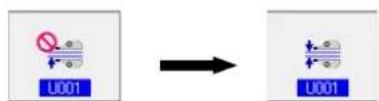
(Set the manipulators referring to "VI-19. Changing the memory switch data" p.85.)
When you press the READY key , the
sewing screen (green) is displayed, the presser foot of the sewing machine goes up and LED ① flashes on and off to inform you that the sewing machine is brought to the set-ready state for sewing.
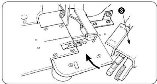
text_image
Technical diagram of a sewing machine mechanism with labeled parts and directional arrows indicating motion or assembly.
text_image
Technical diagram of a sewing machine with numbered parts labeled 6 and 7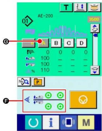
text_image
AE-200 3500 G A B C D 0 0 0 0 100 100 110 No P F
text_image
Technical diagram showing mechanical assembly with numbered components and directional arrows indicating motion or movement.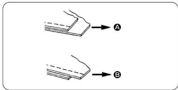
text_image
Diagram showing two labeled components A and B with arrows indicating direction or flow, likely illustrating a physical or engineering concept.Rotate upper manipulator ③ back to its home position.
Place the materials on the cloth guide with the material ends aligned with material alignment line 6.
Once you have placed the material on the sewing machine, the sensor display on the sewing screen changes its status to ON state(F) and LED① flashes on and off. When you press the START switch ②, the sewing machine starts running while manipulators ⑦ work to align the material ends. At the end of sewing, the sewing machine automatically performs thread trimming and stops.
⑨ If the material ends are not aligned with each other at the end of sewing, change the upper/lower manipulator pressure to align the material ends at the end of sewing.
In the case of ( A ), select sewing parameter [S80] section A - upper manipulator presser and decrease the upper manipulator pressure value.
In the case of ( B ), select sewing parameter [S81] section B - lower manipulator presser and decrease the lower manipulator pressure.

If the manipulator pressure is excessively decreased, width of seam allowances will not be consistent.
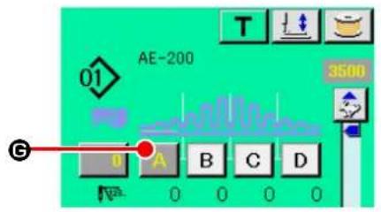
text_image
AE-200 3500 01 G A B C D N 0 0 0 0
text_image
S082 0 S080 100 S081 100 S040 110 S041 3500 S042 0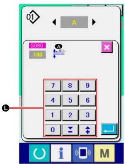
text_image
01 A S080 100 7 8 9 4 5 6 1 2 3 0 ↓ ↑ L⑩ Operation for changing the upper manipulator pressure
When you press SECTION A button ( A G ), the sewing data change screen is displayed.
Changing the upper manipulator pressure data
Change the pressure value ( Ⓗ) of the upper manipulator in upper manipulator pressure
S080 field with -/+ buttons (▼ + ⬤).
In this state, place the material on the sewing machine. Then, start the sewing machine to carry out sewing.
At the time when the sewing machine performs thread trimming at the end of sewing, the upper manipulator pressure value (H) you have changed is determined.
⑪ Operation for changing the lower manipulator pressure
When you press SECTION A button ( A G ), the sewing data change screen is displayed.
Changing the lower manipulator pressure data
Change value ( ①) of the lower manipulator pressure to lower manipulator pressure using -/+ button (▼ + K) or numeric keypad (L).
At the time when the sewing machine performs thread trimming at the end of sewing, the upper manipulator pressure value (①) you have changed is determined.
Recommended manipulator pressure (for linear patterns)
| Light-weight materials Medium-weight materials Heavy-weight materials | ||
| Upper manipulator pressure 65 | to 85 90 to 110 120 to 130 | |
| Lower manipulator pressure 70 | to 90 100 to 120 140 to 160 | |

If the lower manipulator pressure is set to 65 when the bottom feed pitch is set at 2.5 mm or more, error [E499] will displayed to disable sewing.
2. Material auxiliary feed air blow
2-1. Material blowing air nozzles
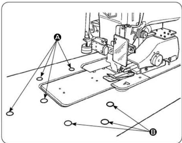
text_image
Technical diagram of a sewing machine with labeled points A and B, showing alignment lines and connection points.2-2. Adjusting the air blow-off pressure
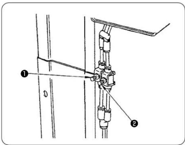
text_image
Technical diagram showing mechanical assembly with labeled parts 1 and 2, likely for assembly or maintenance instructions.3. Hand switch

CAUTION :
When you press the start switch, the presser foot of the sewing machine comes down. Be careful not to allow your fingers to be caught under the presser foot.
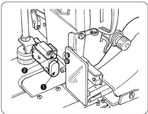
text_image
Technical diagram of a mechanical assembly with numbered components, likely for assembly or maintenance instructions.1) Air nozzles are provided at seven locations on the table. Air nozzles (A) are provided at four locations in front of the needle center and those (B) are provided at three locations behind the needle center.
2) Adjust the speed controllers for (A) and (B) in accordance with the type of material, shape and size of the workpiece. (Refer to "2-2. Adjusting the air blow-off pressure" p.149.) Adjust the speed controllers to increase the air blow-off pressure for large and heavy workpieces or to decrease it for small and light ones.

Do not move your face near the blow-off air outlet.
1) Adjust the air blow-off pressure by means of speed controllers ① and ②.
2) Speed controller ① is used for adjusting the blow-off pressure of (A), and speed controller ② is used for adjusting the blow-off pressure of (B).
4. Material end sensor
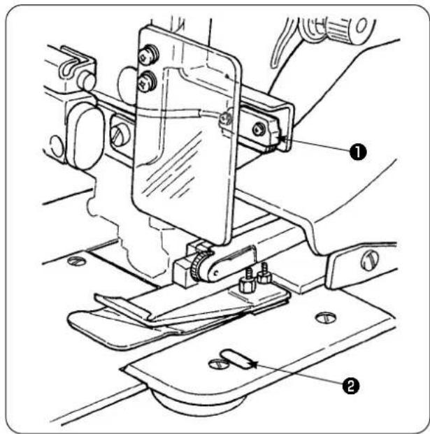
text_image
Technical diagram of a sewing machine with numbered parts labeled ① and ②1) When material end sensor ① detects the end of material, the speed of stitch drops to 1,500 sti/min if the machine runs at 1,500 sti/min or more. (The factory-set value is 1,500 sti/min.)
2) When reflecting strip ② does not reflect light sufficiently, a malfunction can be caused. If any malfunction has occurred, replace the reflecting strip with a new one. (Part number: 40088020)
3) The initial value of the speed of stitch of the machine head after detection of the material end has been factory-set to 1,500 sti/min. However, it can be changed to 200 to 3,500 sti/min in accordance with process on the operation panel.
5. Adjusting the seam allowance

natural_image
Technical line drawing of a sewing machine with mechanical components and directional arrows indicating motion (no text or symbols)1) Seam allowance is changed by turning seam allowance adjusting knob ①. It is adjustable from 1 mm to 30 mm.

text_image
Technical diagram of a sewing machine with labeled component and directional arrow indicating movement or assembly.2) Check to be sure that swing arm ② smoothly moves up and down by pressing it with fingers.
6. Adjusting height of the upper manipulator roller
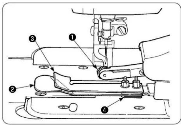
text_image
Technical diagram of a sewing machine with numbered parts labeled 1 to 4
text_image
Technical diagram of a mechanical assembly with numbered components, likely for assembly or maintenance instructions.1) When you have replaced the sensor and cloth guide asm. ④ (refer to pages 153 and 154 for how to replace them), it is necessary to adjust the clearance between roller ① and separation plate ②.
2) Loosen setscrew ⑤ and move roller ① up and down to adjust so that the roller height matches cloth guide asm. ④ . It is necessary to adjust the height of roller ① so that its underside (out periphery) does not project from the bottom face of cloth guide ③ . Then, secure the roller with setscrew ⑤ .
Secure the roller with the end face of upper manipulator shaft ⑥ aligned with the end face of manipulator driving arm ⑦.
7. Pin tuck device S200 for AE-200A, AE-200AN

CAUTION :
To avoid possible accident due to abrupt start of the sewing machine, turn off the power to the machine and make sure that the machine does not run even when you depress the start pedal.
7-1. Specifications

text_image
Height of pin tuck crest Interval- Pin tuck size
Height of pin tuck crest: 1 to 30 mm
Interval: 4 to 25 mm
* The possible combination of specifications is "Height of crest + Interval = 50 mm" or less.
- Speed of stitch: The best suited speed of stitch is 2,000 to 2,500 sti/min.
7-2. Adhering a scale

natural_image
Technical line drawing of a sewing machine needle and measuring tool (no text or symbols)When the pink tuck device is retrofitted to the sewing machine, the scale label supplied with the unit should be adhered on the sewing machine.
Adhere the scale label on the sewing machine with its 0 (zero) position aligned with the needle entry line as illustrated in the sketch at left.
7-3. Replacing the upper manipulator sensor and cloth guide
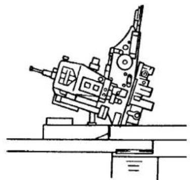
natural_image
Technical line drawing of a mechanical device with no visible text or symbols1) To replace the sensor, tilt the sewing machine and swing the upper manipulator.

Be careful not to allow the upper manipulator to fall when you swing the upper manipulator.

natural_image
Mechanical assembly diagram showing a bracket with labeled parts (no text or symbols present)2) Remove two sensor holder setscrews ①. Remove the sensor holder.

text_image
Technical diagram of a mechanical assembly with numbered component annotations3) Remove two sensor setscrews ②. Remove the sensor. Change the standard sensor with the exclusive pin tuck sensor (part number: 40084103).

When securing the manipulator, adjust so that the sensor does not come in contact with the slots in the throat plate by means of two sensors ②.
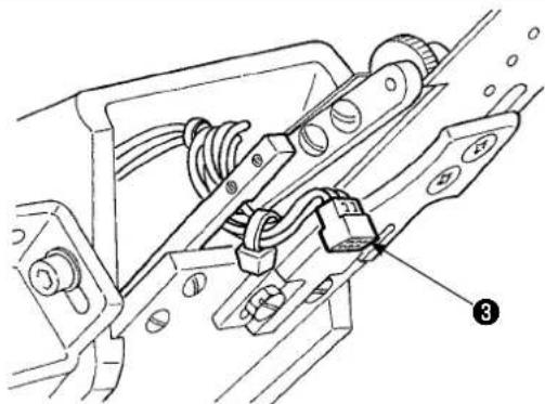
natural_image
Technical line drawing of a mechanical assembly with no visible text or symbols4) Remove sensor connector ③ from the sensor. At this time, be sure to handle the connector section since it is very thin.

When installing the sensor connector, carefully check the orientation of the connector. (Align with the connector mark.)
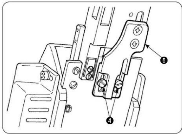
text_image
Technical diagram of a mechanical clamp or bracket assembly with numbered parts labeled 4 and 55) Remove two cloth guide setscrews ④. Remove cloth guide ⑤.
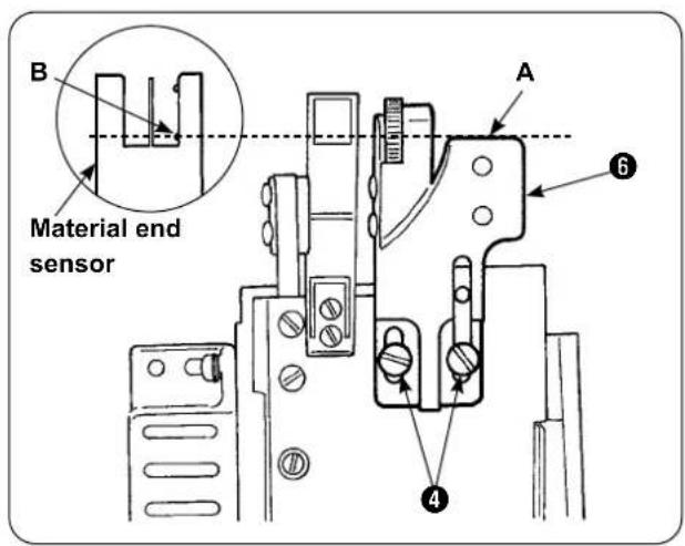
text_image
B Material end sensor A ④ ⑥6) Install tucking ruler base plate ⑥ with two cloth guide setscrews ④. Adjust tucking ruler base plate ⑥ so that face (A) of tucking base plate ⑥ is flush with section (B) of material end sensor (B).

text_image
Technical diagram of a mechanical device with numbered parts labeled 6, 7, and 87) Mount tucking ruler ⑦ on tucking ruler base plate ⑥ with tucking ruler setscrews ⑧.
7-4. Installing the ruler
For the location of main-body ruler related parts, place the mounting base at the location shown in Fig. 1 and Fig. 2.
Fig. 1 Mounting location of the ruler with respect to widthwise direction
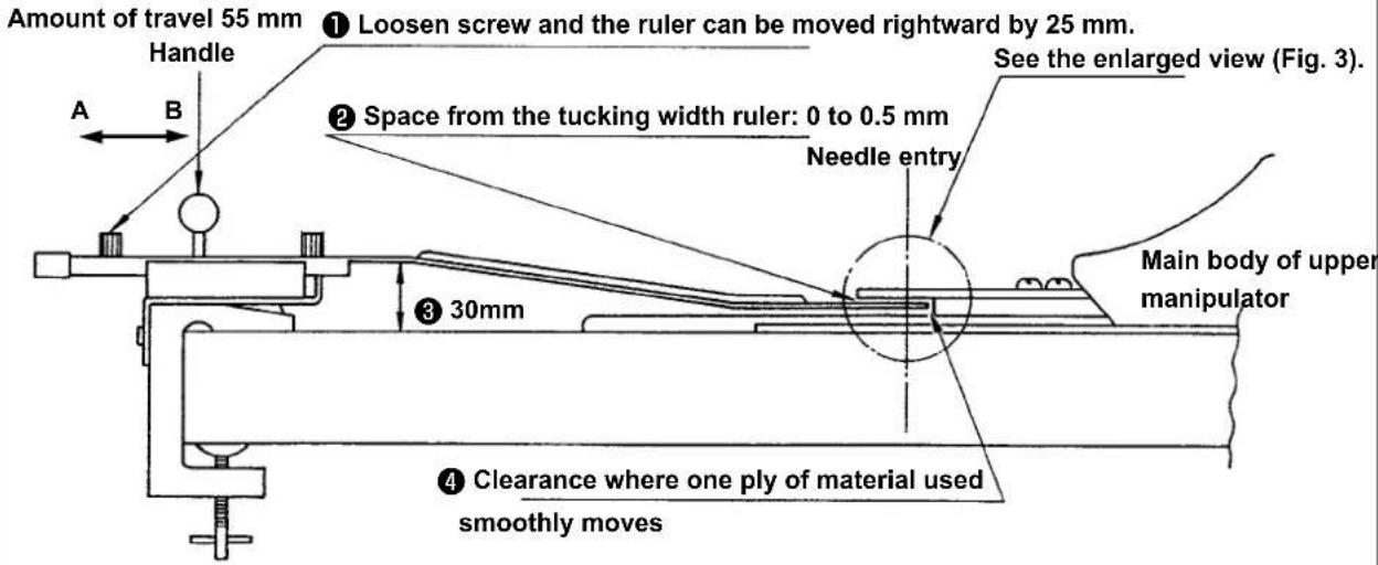
text_image
Amount of travel 55 mm Handle A B ① Loosen screw and the ruler can be moved rightward by 25 mm. See the enlarged view (Fig. 3). ② Space from the tucking width ruler: 0 to 0.5 mm Needle entry Main body of upper manipulator 30mm ③ Clearance where one ply of material used smoothly movesInstall the mounting base on the leftmost table, and set the pin tuck ruler at the location which satisfies conditions ② and ④.
Fig. 2 Mounting location of the ruler with respect to lengthwise direction
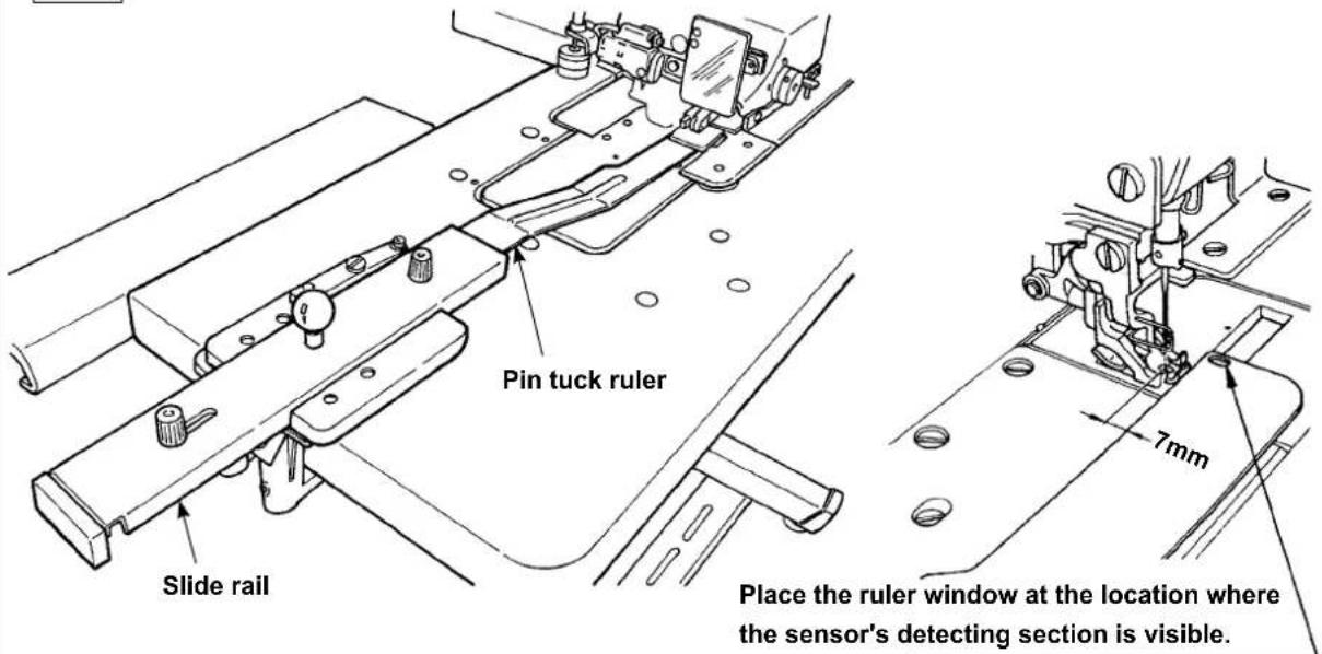
text_image
Pin tuck ruler Slide rail Place the ruler window at the location where the sensor's detecting section is visible. 7mmWith respect to the face plate, install the mounting base on the machine table so that the front end of pin tuck ruler is spaced 7 mm from the needle entry (in parallel to the red line). At this time, place the ruler at the location where two sensor detecting sections under the base are visible.
Fig. 3 Sewing position
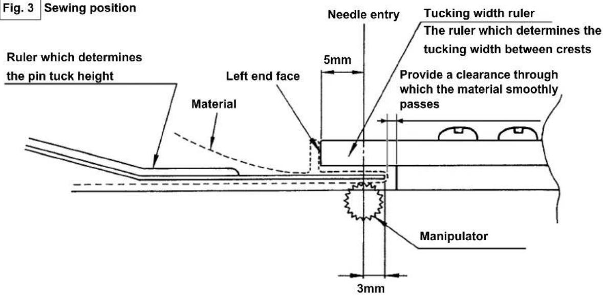
text_image
Fig. 3 Sewing position Ruler which determines the pin tuck height Material Left end face Needle entry 5mm Tucking width ruler The ruler which determines the tucking width between crests Provide a clearance through which the material smoothly passes Manipulator 3mmFig. 4 Example of use

text_image
3mm 5mmFor sewing pin tucks of 5 mm in tucking width and 3 mm in height, the mounting location of the ruler is as illustrated in Fig. 3. The finished pin tucks are as illustrated in Fig. 4.
Fig. 5 Needle entry

text_image
Sew the first pin tuck with pressed against the tucking width ruler while guiding the material by hand.Sewing procedure
Select "without automatic material alignment" in [S02] "automatic material alignment" on the operation panel. Select "one piece sewing" in [S04] "changeover of No. of pieces to be sewn" [S04].

Sewing of the first pin tuck is most important since it is used as reference. Extremely careful when sewing the pin tuck. Note that the manipulator pressure should be set to a relatively lower value for sewing the first piece of material.
■ Method for setting the operation panel
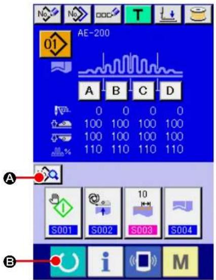
text_image
AE-200 A B C D 0 0 0 0 100 100 100 100 100 100 100 100 110 110 110 110 A S001 S002 S003 S004 B i M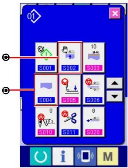
text_image
01 S001 S002 10 S003 S004 S005 S006 0 8 S010 S011 S020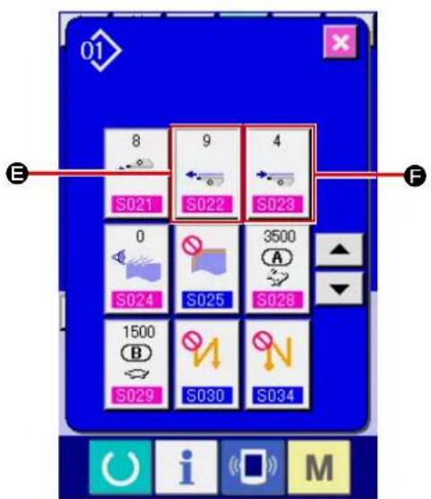
text_image
8 9 4 S021 S022 S023 0 S024 S025 3500 A S028 1500 B S029 S030 S034 E F i M① Displaying the data input screen.
The set contents can be changed only on the data input screen (blue). In the case the sewing screen (green) is displayed, press READY key

(B) to display the data input screen.
② Displaying the sewing data editing screen.
When press SEWING DATA EDIT button

(A) on the data input screen, the sewing data screen is displayed. On this screen, the sewing data of the currently-selected pattern can be edited.
③ Changing the sewing data.
Select [S02] "Automatic material alignment
"(©). Select "Without automatic material alignment".

Select [S04] "Changeover of number of pieces to be sewn" (D). Select "One piece sewing".
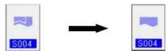
Select [S22] "Manipulator lower rake-out speed" (E). Change the set value from 8 to 9.
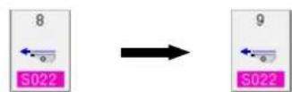
Select [S23] "Manipulator lower pull-in speed" (F). Change the set value from 8 to 4.

After you have completed the setting procedure, press the READY key (O) to bring the sewing machine back to the set-ready state for sewing. Then, run the sewing machine.
Fig. 6
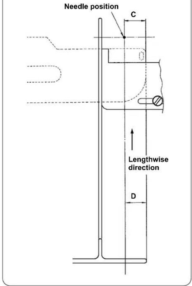
text_image
Needle position C Lengthwise direction D1) Draw the handle of the pin tuck ruler in direction (A) as shown in Fig. 1. When you have brought the ruler away from the material, fold the material into two (at the dotted line) as shown in Fig. 5 and sew the material with pressed against the guide. For the first piece of material, it is recommended to fold the material into two with an iron or the like beforehand to make a reference line to be used to fold it on the sewing machine.
2) Put the first piece of material onto the left end face of the tucking width ruler (see Fig. 3), move the handle in direction (B) in such a way as to insert the pin tuck ruler under the material (see Fig. 1), and secure the slide rail with the magnet (see Fig. 2). Place the top end of the material with respect to the direction of sewing at the needle entry position, press the start switch or depress the pedal to start sewing. It is recommended to guide the material with your right or left hand during sewing to achieve neat finish.
3) Set the lower manipulator pressure at 90 to 120 first. Then, adjust it in accordance with the material to be used. The best-suited speed of stitch is 2,000 to 2,500 sti/min.
4) If the crests of pin tucks warp, adjust the top feed amount.
5) The tucking width ruler comes in four different types, S, A, B, and C. The S type ruler is for pin tucks with a lower crest. The C type ruler is for pin tucks with a higher crest. Change the ruler according to the pin tuck specifications.
6) As shown in Fig. 1, the clearance provided between the pin tuck ruler and the tucking width ruler greatly affects the finish quality of pin tucks. When you place the material on the machine, be sure to check that the material moves smoothly. If the material does not move smoothly, bend the pin tuck ruler by hand to correct it appropriately.
7) For sewing conditions where pin tucks crest height (C) of which is more than 15 mm as shown in Fig. 6, set (D) section of the material firstly to the same width as C in the figure, then start sewing.
VIII. ADJUSTING THE SEWING MACHINE
1. Adjusting the presser foot lifting lever
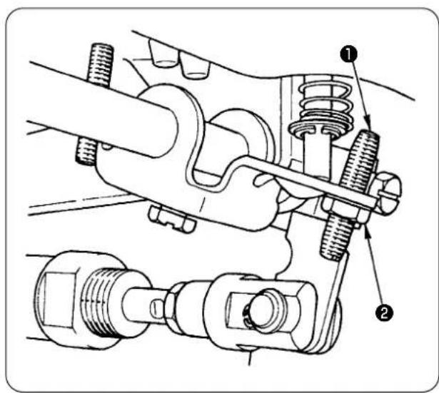
text_image
Technical diagram of a mechanical assembly with numbered components, likely illustrating engine or coupling mechanism.1) The maximum lift of the presser foot by means of the presser foot lifting lever is 10 mm.
2) The presser foot lift can be adjusted by means of presser foot lifting lever adjusting screw ①.
3) To increase the presser foot lift, re-adjust it by loosening nut ② and adjusting screw ①.

If you start the sewing machine with presser foot ③ raised by presser foot lifting lever, the needle bar may hit against walking foot ④. So, be careful.
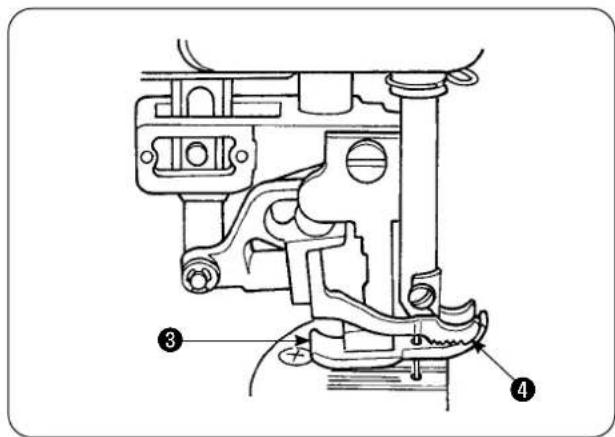
text_image
Technical diagram of a mechanical assembly with numbered parts labeled 3 and 4When you have changed the setting of [U25] to "Material placement with the needle lowered" as described in "VI-20-[U24] Material placement with the needle lowered" p.89 lower the presser foot height by the presser foot lifting lever.
If it is not adjusted, the needle bar will come in contact with the presser foot and the walking foot when the needle bar comes down by pressing the START button. It is therefore necessary to adjust the presser foot height.
2. Thread tension
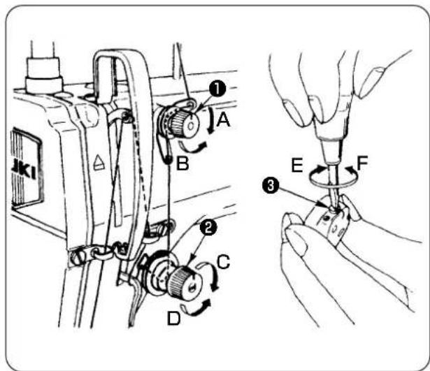
text_image
Technical diagram showing mechanical assembly steps with labeled components A, B, C, D and numbered parts 1, 2, 3, E, F1. Adjusting the needle thread tension
1) The length of thread remaining at the needle after thread trimming is shortened by turning tension regulating nut No. 1 ① clockwise (A).
2) The aforementioned thread length is lengthened by turning the tension regulating nut No. 1 counterclockwise (B).
3) The needle thread tension is increased by turning tension regulating nut ② clockwise (C).
4) The tension is decreased by turning the tension regulating nut counterclockwise (D).
2. Adjusting the bobbin thread tension
1) The bobbin thread tension is increased by turning bobbin thread tension regulating spring ③ clockwise (E).
2) The tension is decreased by turning the thread tension regulating spring counterclockwise (F).
3. Thread take-up spring
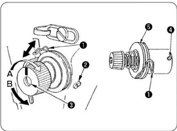
text_image
Technical diagram of a mechanical assembly with labeled parts and directional arrows indicating motion or movement.4. Presser foot lifting lever
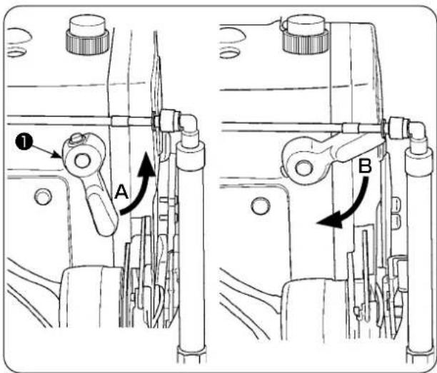
text_image
Technical diagram showing mechanical assembly with labeled parts A and B, including directional arrows and numbered annotations.5. Adjusting the presser foot pressure

CAUTION :
To avoid possible accident due to abrupt start of the sewing machine, turn off the power to the machine beforehand.

text_image
A B ① h ②- To change the stroke of thread take-up spring ①
1) Loosen setscrew ② in the tension post socket.
2) The stroke is increased by turning tension post ③ clockwise (A).
3) The stroke is decreased by turning the tension post counterclockwise (B).
- To change the pressure of thread take-up spring ①
1) Loosen setscrew ②, and remove thread tension regulator (asm.) ⑤.
2) Loosen setscrew ④ in the tension post.
3) The pressure of the thread take-up spring is increased by turning tension post ③ clockwise (A).
4) The tension is decreased by turning the thread tension regulating spring counterclockwise (B).
1) To stop the presser foot at the raised position, turn presser foot lifting lever ① in direction (A).
2) The presser foot goes up by 5 mm and stops. The presser foot returns to its home position by turning presser foot lifting lever downward in direction (B).
3) The presser foot can be raised up to approximately 10 mm by means of the presser foot lifting lever.
1) Loosen nut ②. The pressure foot pressure is increased by turning presser spring regulator ① clockwise (A).
2) The tension is decreased by turning the tension regulating nut counterclockwise (B).
3) After the adjustment, tighten nut ②.
4) For general fabric, standard height ( h) of the presser spring regulator is approximately 45 mm.

If the presser foot pressure and walking foot pressure are excessively high, the presser foot may fail to go up to its highest position when the auto-lifter is used.
6. Adjusting the walking foot pressure

CAUTION :
To avoid possible accident due to abrupt start of the sewing machine, turn off the power to the machine beforehand.
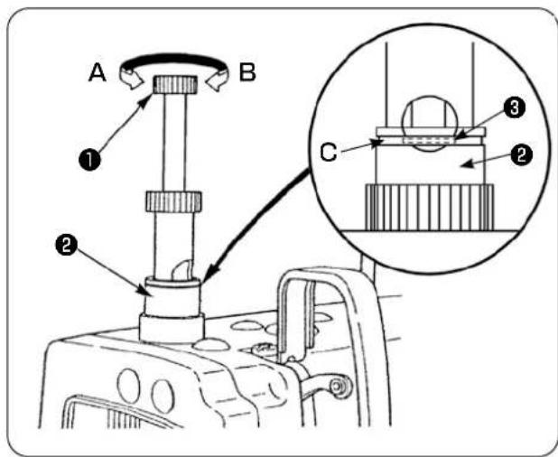
text_image
A B ① ② C ③ ②1) The walking foot pressure is increased by depressing walking foot pressure regulating knob ① and turning it clockwise (A), or decreased by turning it counterclockwise (B).
(Be sure to turn the walking foot pressure regulating stud with securely depressed.)
2) The standard pressure of the working foot is obtained when snap ring ③ (silver) located inside the circular hole in the pressure regulator spring is aligned with the white line (C) on pressure regulating nut ② when walking foot pressure regulating stud ① is depressed.
3) Adjust the walking foot pressure according to the type of material and process referring to the standard value obtained as described above.

If the walking foot pressure is excessive or the presser foot pressure is lower than the walking foot pressure, the presser foot may rise above the standard position. In this case, the presser foot may not provide adequate efficiency of feed or may damage the material. So be careful.
7. Adjusting the thread take-up amount by thread take-up lever

CAUTION :
To avoid possible accident due to abrupt start of the sewing machine, turn off the power to the machine beforehand.

text_image
A B 1 C1) When sewing a heavy-weight material, increase the thread take-up amount by moving take-up thread guide ① leftward (A).
2) When sewing a light-weight material, decrease the thread take-up amount by moving take-up thread guide ① rightward (B).
3) The standard position of needle thread guide ① is obtained by aligning marker line (C) with the center of the screw.
8. How to adjust the amount of oil (oil splashes) in the hook

CAUTION :
The hook rotates at a high speed since the oil amount is to be checked while the machine is in operation. Be extremely careful when you adjust the oil amount in order to protect against personal injury.
① Oil amount (oil splashes) confirmation paper
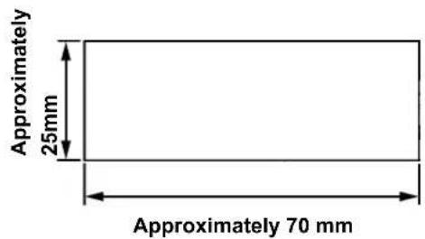
text_image
Approximately 25mm Approximately 70 mm*Use any paper available regardless of the material.
② Position to confirm the oil amount (oil splashes)

text_image
Hook driving shaft front bushing Approximately 3 to 10 mm Oil splash confirmation paper Oil reservoir Closely fit the paper against the side face of the bed. Bed* Place the oil amount (oil splashes) confirmation paper under the hook.

CAUTION :
When checking the amount of oil (oil splashes) in the hook, be extremely careful not to allow your fingers to come in contact with the hook.
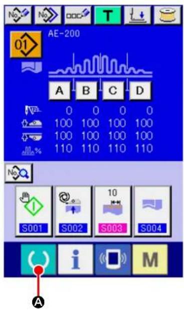
text_image
AE-200 01 A B C D 0 0 0 0 100 100 100 100 100 100 100 100 110 110 110 110 S001 S002 S003 S004 A i M
text_image
Technical diagram of a mechanical assembly with numbered components, likely for assembly or maintenance instructions.① Turning ON the power to the sewing machine.
When you turn ON the power to the sewing machine, the initial screen is displayed to allow you to change the set contents.
② Setting the start mode to the manual mode.
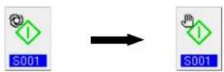
(Set the start mode referring to ing sewing data" p.57.)
"VI-10. Chang-
③ Stopping operation of the manipulators.
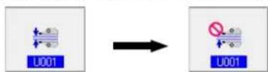
(Set the manipulators referring to "VI-19. Changing the memory switch data" p.85.)
④ When you press the READY key ( A ), the sewing screen is displayed, presser foot of the sewing machine goes up and LED ① flashes on and off.

text_image
A B* If the machine head is not sufficiently warm, idle the machine for approximately three minutes. (Moderate intermittent operation)
* Place the oil amount (oil splashes) confirmation paper under the hook while the sewing machine is in operation.
* Check to be sure that the oil level in the oil reservoir is between HIGH and LOW.
* The length of time required for checking the oil amount (oil splashes) is five seconds. (Check the length of time with a watch.)
• Sample showing the appropriate amount of oil

text_image
Splashes of oil from the hook Approximately 1mm Appropriate amount of oil (small) Splashes of oil from the hook Approximately 2mm Appropriate amount of oil (large)1) The appropriate amount of oil shown in the sample at left has to be finely adjusted to increase or decrease in accordance with the sewing process. Be extremely careful not to excessively increase or decrease the oil amount.
• Excessively small amount of oil =
The hook will be seized (the hook will be hot).
- Excessively large amount of oil =
The product will be stained with oil.
2) Check the oil amount (oil splashes) three times (with three sheets of paper). Adjust the oil amount so that it does not change among three times of checking.
- Adjusting the amount of oil (oil splashes) in the hook

text_image
A B1) The oil amount (oil splashes) in the hook is increased by turning the oil amount adjustment screw mounted on the hook driving shaft front bushing in direction (A) (toward “+”), or decreased by turning it in direction (B) (toward “-”).
2) After the adjustment of the oil amount in the hook with the oil amount adjustment screw, idle the sewing machine for approximately 30 seconds. Then, check the oil amount (oil splashes).

CAUTION :
To avoid possible accident due to abrupt start of the sewing machine, turn off the power to the machine beforehand.
- Adjustment of the oil amount in the frame

text_image
C B A ① ②1) Adjust the amount of oil supplied to the thread take-up lever and needle bar crank section ② by turning oil amount adjust pin ①.
2) The oil amount supplied is minimized when marker dot (A) on the adjust pin is brought near needle bar crank ② by turning the adjust pin in direction (B).
3) The oil amount supplied is maximized when marker dot A on the adjust pin is brought to the direct opposite position of needle bar crank ② by turning the adjust pin in direction (C).
9. Needle-to-hook relation

CAUTION :
To avoid possible accident due to abrupt start of the sewing machine, turn off the power to the machine beforehand.

text_image
Technical diagram of a sewing machine with labeled parts and exploded viewsAdjust the timing between the needle and the hook as follows:
1) Turn the handwheel to bring the needle bar down to the lowest point of its stroke. Loosen needle bar connection setscrew ①.
2) Determine the needle bar height.
[For DB needle]
Align marker line ( A ) on needle bar ^② with the bottom end of needle bar lower bushing ^③ , and tighten needle bar connection setscrew ^① . [For DA needle]
Align marker line ( C ) on needle bar ② with the bottom end of needle bar lower bushing ③ , and tighten needle bar connection setscrew ① .
3) Determine the mounting position of hook ⓐ. [For DB needle]
Loosen three setscrews in the hook. Turn the handwheel to align marker line (B) with the bottom end of needle bar lower bushing ③ while needle bar ② is going up.
[For DA needle]
Loosen three setscrews in the hook. Turn the handwheel to align marker line (D) with the bottom end of needle bar lower bushing ③ while needle bar ② is going up.
4) In the aforementioned state, align hook blade point ⑤ with the center of needle ④. Adjust so that a clearance of 0.04 to 0.1 ~mm (reference value) is provided between the needle and hook, then securely tighten the hook setscrews.
![JUKI AE-200AN - [For DA needle] - 1](/content/2026/06/1214279/images/a2dc248ba71d417a6b4033e360866d20e0c0548d982c7330b08f6250f28d6cab.jpg)
If the aforementioned clearance is smaller than the specified value, the hook blade point will be damaged. If the clearance is larger than the specified value, stitch skipping will result.
* The part number of the hook used is 11038650. Replace the hook with a hook with the same part number when necessary.
10. Counter knife

CAUTION :
- To avoid possible accident due to abrupt start of the sewing machine, turn off the power to the machine beforehand.
• To prevent personal injury or death, keep your hands and fingers away from the knife blade. - To prevent accidents caused by the worker's unfamiliarity to the machine or by improper adjustment, the sewing machine shall be maintained by a maintenance technician who is familiar to the sewing machine and has been trained in maintenance.
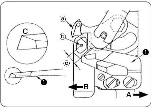
text_image
Technical diagram of a mechanical assembly with labeled parts and directional arrows, including sectional view and component annotations.1) When the knife has become blunt, re-sharpen counter knife ① as illustrated in Fig. (C) and re-install it properly.
2) When the counter knife is moved rightward ( A ) from the standard mounting position, the length of thread remaining after thread trimming becomes longer than the standard length by the length of move of the knife.
3) When the counter knife is moved leftward ( B ), the length of thread becomes shorter than the standard length by the length of move of the knife.
a Moving knife
b Center of needle
© Standard: 4.0 mm
11. Adjusting the feed timing

CAUTION :
To avoid possible accident due to abrupt start of the sewing machine, turn off the power to the machine beforehand.
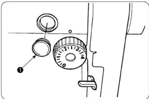
text_image
Diagram of a washing machine dial with numbered adjustment knob and labeled component1) Remove rubber plug ① and carry out adjustment.

After completion of the adjustment, apply sealing agent to rubber plug 1 and mount it back to its position.
2) Loosen setscrews ③ and ④ in feed eccentric cam ② and move the feed eccentric cam in the direction of the arrow or the opposite direction of the arrow for adjustment. Then, securely tighten the setscrews.
3) To adjust to the standard timing, adjust so that the top face of the feed dog and top end of the needle eyelet are aligned with the top face of the throat plate when the feed dog comes down under the throat plate.
4) To advance the feed timing for the purpose of prevention of uneven material feed, move the feed eccentric cam in the direction of the arrow.
5) To retard the feed timing for the purpose of produce well-tensed seams, move the feed eccentric cam in the opposite direction of the arrow.

If the feed eccentric cam is excessively moved from the standard position, needle breakage will be caused.

text_image
(Standard) Needle Feed dog Throat plate (Feed timing is advanced) Feed timing is retarded12. Inclination of the feed dog

CAUTION :
To avoid possible accident due to abrupt start of the sewing machine, turn off the power to the machine beforehand.
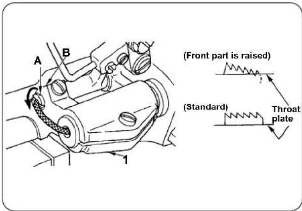
text_image
(Front part is raised) (Standard) Throat plate1) The standard inclination (horizontal) of the feed dog is obtained when marker dot (A) on the feed bar shaft is aligned with section (B) of feed bar base arm ①.
2) To adjust the inclination of the feed dog so that its front part is raised for the purpose of prevention of puckering, loosen the setscrew, insert a screwdriver into the feed bar shaft and turn the shaft in the direction of the arrow by 90 degrees of an angle.
3) To adjust the inclination of the feed dog so that its rear part is raised for the purpose of prevention of uneven material feed, turn the shaft in the opposite direction of the arrow by 90 degrees of an angle.

When you have adjusted the feed dog inclination, the feed dog height may change. So, be sure to re-check the feed dog height.
13. Height of the feed dog

CAUTION :
To avoid possible accident due to abrupt start of the sewing machine, turn off the power to the machine beforehand.

text_image
0.7 ~ 0.8mm Feed dog Throat plate1) Jutting amount of the feed dog from the throat plate has been factory-adjusted to 0.7 to 0.8 mm at the time of delivery.
2) In the case of sewing a light-weight material, stitch gathering may result if the jutting amount of the feed dog is excessive.
3) To adjust the height of the feed dog
① Loosen clamping screw ② in feed driving arm ①.
② Adjust the feed dog height by moving the feed bar up or down.
③ Securely tighten clamping screw ②.
14. Lateral position of the feed dog
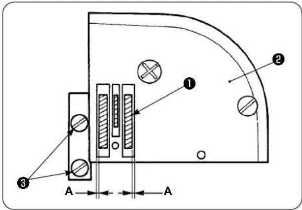
text_image
Technical diagram of a mechanical or electrical component with labeled parts and dimension annotations1) Adjust the lateral position of feed dog ① so that right and left clearances A between the feed dog ① and slots in throat plate ② are in parallel and equal by means of setscrews ③ in the feed dog. After the adjustment, secure the feed dog by tightening the setscrews.
15. Precautions to be taken when correcting the longitudinal position of the walking foot

CAUTION :
To avoid possible accident due to abrupt start of the sewing machine, turn off the power to the machine beforehand.
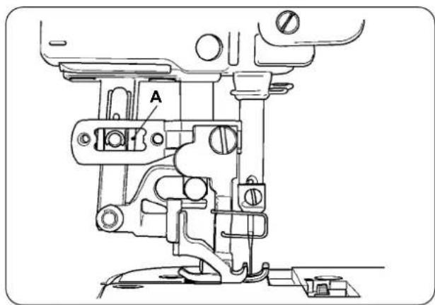
text_image
A1) The standard lateral position of the walking foot is obtained when a clearance of 1 mm is provided in section (A) by maximizing the top feed amount and bringing the walking foot to the front end position of its stroke. Adjust the longitudinal position of the walking foot so as to avoid abnormal noise or extra load while the sewing machine is in operation.
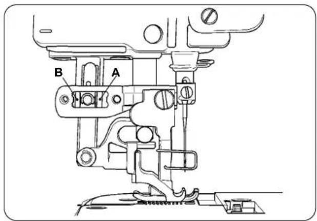
text_image
B A2) To operate the sewing machine with the longitudinal position of the walking foot slightly displaced, be sure to secure a clearance of 1 mm or more at sections (A) and (B) with the feed amount maximized.
IX. MAINTENANCE AND INSPECTION
1. Draining the filter regulator

CAUTION :
To avoid possible accident due to abrupt start of the sewing machine, turn off the power to the machine and make sure that the machine does not run even when you depress the start pedal.
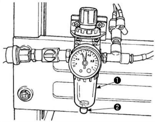
text_image
Technical diagram of a pressure regulator with labeled parts 1 and 21) Drain regulator ① before using the sewing machine to expel water from the regulator. (Loosen knob ② to drain the regulator.)
2) Water content affects the pneumatically controlled components. So, be careful.
3) When the air pressure drops, the pressure gauge switch for regulator ① is activated to cause an error.
2. Cleaning the sensor

CAUTION :
To avoid possible accident due to abrupt start of the sewing machine, turn off the power to the machine and make sure that the machine does not run even when you depress the start pedal.

natural_image
Pure mechanical diagram showing a tool interacting with a bracket (no text or symbols)1) When sensor is stained with dust, malfunction will result. Blow away dust from the lens, slits, angular part at the back of the sensor, and reflecting plate with an air gun supplied with the unit. 2) When the sensor is stained with oil, dust will easily gather on the sensor. If the sensor is stained with oil by any possibility, remove it with benzine or the line immediately.

Carefully clean up the slit in the throat plate sensor in particular.
3. Lubricating the manipulator roller section

CAUTION :
To avoid possible accident due to abrupt start of the sewing machine, turn off the power to the machine and make sure that the machine does not run even when you depress the start pedal.

text_image
Upper maLower manipulator
1) If the upper/lower manipulator shaft section generates abnormal noise, apply a little amount of grease on to the shaft section. (The sections shown with bold arrows in the illustration.)
4. Replacing the fuse

CAUTION :
- In order to prevent accidents caused by electrical shock, be sure to turn OFF the power to the sewing machine and wait for five minutes before opening the cover.
- Be sure to open the control box cover after having turned OFF the power switch, and replace the fuse with a new one of the designated capacity.
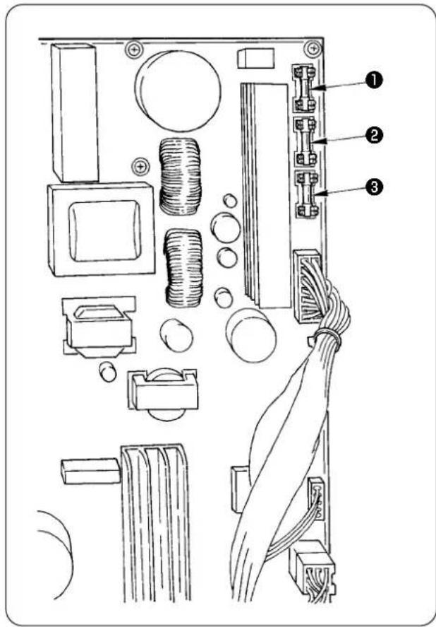
text_image
Technical diagram of an electronic circuit board with labeled components and wiring connectionsUse three fuses.
① For protection of the power to the stepping motor 5 A (Time lag fuse)
② For protection of the power to the solenoid and stepping motor
3.15 A (Time lag fuse)
③ For protection of the power to the control box 2 A (Quick blowout type fuse)
5. List of optional parts for AE-200AN
| Part name Part number | |
| Pin tuck device 40088621 | |
| 2-pedal unit 40084064 | |
| Bobbin thread remaining amount detecting device 40088623 | |
| Stacker device 40088624 | |
| Electric bobbin winding device 40088627 | |
| 4/4 sensor for heavy-weight materials 40084101 | |
| 4/4 cloth guide for heavy-weight materials 40088212 | |
| 2/2 sensor for light-weight materials 40084102 | |
| 2/2 cloth guide for light-weight materials 40088211 | |
| Thread breakage detecting device 40088632 | |
| Throat plate for light-weight materials 40098871 | |
| Feed dog for light-weight materials 22881700 | |
| Urethane upper feed dog 40088215 | |
| Cloth guide 4/4 for small curves 18076257 | |
| Cloth guide 4/2 for small curves 18076356 | |
| Cloth guide 2/2 for small curves 18076059 | |
| High-voltage transformer | 40005422 |
6. Disposal of batteries

The operation panel has a built-in battery to back up the memory even when the power to the operation panel is OFF.
Be sure to dispose of the battery following the local laws and regulations.
[How to remove the battery]
![JUKI AE-200AN - [How to remove the battery] - 1](/content/2026/06/1214279/images/8e194d5ceee45707255bfc8fe6f081dcada52b8613130a30631344f1cc889487.jpg)
natural_image
Technical line drawing of a sewing machine with a digital device labeled (no text or symbols present)1) Remove panel ① from the main body of sewing machine.
![JUKI AE-200AN - [How to remove the battery] - 2](/content/2026/06/1214279/images/d0ba68f00ed03a6a5ebcf5d4b493147be37b8e9d84a80048ce34af1c1472ef4a.jpg)
text_image
Technical diagram of a device rear panel with numbered annotations pointing to key components.2) Loosen screw ② from the rear surface of the operation panel. Detach case ③.
![JUKI AE-200AN - [How to remove the battery] - 3](/content/2026/06/1214279/images/2aa6606bedf521c19f3713ed4a0b435bb512b3e53f5a4e0198e8c9417f475d10.jpg)
text_image
Technical diagram of a device casing with numbered components for identification3) Remove screws ④ and remove copper foil tape ⑤. Detach shielding plate ⑥.
![JUKI AE-200AN - [How to remove the battery] - 4](/content/2026/06/1214279/images/7fd63c4648184ba72fd2a2c88d259a11a17c0a7ed42ceaed6dd9b45b898df3bd.jpg)
text_image
Diagram of a device rear panel with labeled components and directional arrows indicating movement or flow.4) ⑦ is the backup battery. Model number: VL1220/HFR
![JUKI AE-200AN - [How to remove the battery] - 5](/content/2026/06/1214279/images/d8bfa013a99219a9bcc4b87e1c4c77b518f44ea28573573a78e25152f472fa44.jpg)
text_image
A direction side B direction side5) Cut metal plate (D) that secures battery 7 with nippers or the like at position (A). 6) Cut metal plate (C) that secures battery 7 with nippers or the like at position (B). Then, remove battery 7.
![JUKI AE-200AN - [How to remove the battery] - 6](/content/2026/06/1214279/images/6e6b403324ffbd954b7524a8b626fb732e397f9d5ac8e9fa96eb30ca10fd10cc.jpg)
text_image
Carefully protect your fingers from being cut with the cut edge of the metal plate.- Setting data recording paper for AE-200AN
| 1 2 3 4 | 5 6 7 8 9 10 | |||||||||
| Name of sewing | Factory-delivered state | Factory-delivered state | ||||||||
| Pattern number 1 1 2 3 | ||||||||||
| Process (2-ply joining, pin tuck) | 2-ply sewing | Pin tuck | 2-ply sewing | 2-ply sewing | ||||||
| Product name | ||||||||||
| Material type | Contact Intracell Co. | Contact Intracell | ||||||||
| Needle thread; type and yarn count | Span Thread #50 Span thread A#6 | |||||||||
| Bobbin thread; type and yarn count | Span Thread #50 Span thread A#6 | |||||||||
| Needle; type and count | DB×1#11 | DB×1#11 | ||||||||
| Joining edge width (mm) - 3×5mm | ||||||||||
| Sewing machine stitch length 2.5mm 2.5mm | ||||||||||
| Height of the presser spring regulating 45mm 45mm | ||||||||||
| Walking foot regulating knob 53mm 53mm | ||||||||||
| Function setting item | ||||||||||
| Item Description | ||||||||||
| S20 | Upper scrape-out speed of manipulator | 8 8 8 8 | ||||||||
| S21 | Upper draw-in speed of manipulator | 8 8 8 8 | ||||||||
| S22 | Lower scrape-out speed of manipulator | 8 9 8 8 | ||||||||
| S23 | Lower draw-in speed of manipulator | 8 | 4 | 8 | 8 | |||||
| S24 | Cloth fluff detection level | - | - | 0 | 0 | |||||
| S25 | Setting of manipulator-pressure intermittent-adjustment section | No setting | No setting | No setting | No setting | |||||
| S26 | Number of stitches for intermittent interval of upper manipulator pressure | - | - | - | - | |||||
| S27 | Number of stitches for intermittent interval of lower manipulator pressure | - | - | - | - | |||||
| S28 | A speed of machine (rabbit) | 3500 | 2500 | 3500 | 3500 | |||||
| S29 | B speed of machine (turtle) | 1500 | 1500 | 1500 | 1500 | |||||
| S30 | Sewing start - Selection of back tack | Without | Without | Without | Without | |||||
| S31 | Sewing start - Number of back tack stitches - A | - | - | - | - | |||||
| S32 | Sewing start - Number of back tack stitches - B | - | - | - | - | |||||
| S33 | Sewing start - State of back tack manipulator | - | - | - | - | |||||
| S34 | Sewing end - Selection of back tack | Without | Without | Without | Without | |||||
| S35 | Sewing end - Number of back tack stitches - C | - | - | - | - | |||||
| S36 | Sewing end - Number of back tack stitches - D | - | - | - | - | |||||
| S37 | Sewing end - State of back tack manipulator | - | - | - | - | |||||
| S40 | Section A - Shirring amount | - | - | - | - | |||||
| S40 | Section A - Shirring ratio | 110 to130 | 110 | 110 | 110 | |||||
| S41 | Machine head section speed A | 3500 | 3500 | 3500 | 3500 | |||||
| S42 | Shirring changeover position A (number of stitches) | 0 0 0 0 | ||||||||
| S43 | Section B - Shirring amount | - | - | - | - | |||||
| S43 | Section B - Shirring ratio | - | - | - | - | |||||
| S44 | Machine head section speed B | - | - | - | - | |||||
| S45 | Shirring changeover position B (number of stitches) | - | - | - | - | |||||
| S46 | Section C - Shirring amount | - | - | - | - | |||||
| S46 | Section C - Shirring ratio | - | - | - | - | |||||
| S47 | Machine head section speed C | - | - | - | - | |||||
| S48 | Shirring changeover position C (number of stitches) | - | - | - | - | |||||
| S49 | Section D - Shirring amount | - | - | - | - | |||||
| S49 | Section D - Shirring ratio | - | - | - | - | |||||
| S50 | Machine head section speed D | - | - | - | - | |||||
| S51 | Shirring changeover position D (number of stitches) | - | - | - | - | |||||
| S80 | Section A - Upper manipulator pressure | 70 to 100 | 100 | 100 | 100 | |||||
| S81 | Section A - Lower manipulator pressure | 100 to 130 | 100 to 130 | 100 | 100 | |||||
| S82 | Upper/lower manipulator pressure change-over position A (number of stitches) | 0 0 0 0 | ||||||||
| S83 | Section B - Upper manipulator pressure | - | - | - | - | |||||
| S84 | Section B - Lower manipulator pressure | - | - | - | - | |||||
| S85 | Upper/lower manipulator pressure change-over position B (number of stitches) | - | - | - | - | |||||
| S86 | Section C - Upper manipulator pressure | - | - | - | - | |||||
| S87 | Section C - Lower manipulator pressure | - | - | - | - | |||||
| S88 | Upper/lower manipulator pressure change-over position C (number of stitches) | - | - | - | - | |||||
| S89 | Section D - Upper manipulator pressure | - | - | - | - | |||||
| S90 | Section D - Lower manipulator pressure | - | - | - | - | |||||
| S91 | Upper/lower manipulator pressure change-over position D (number of stitches) | - | - | - | - | |||||
| S130 | Selection of stacker operation | Selections of specifications | Selections of specifications | - | - | |||||
| S131 | Stacker operating position | - | - | - | - | |||||
| S132 | Selection of the number of times of stacker operation | - | - | - | - | |||||