AK85C - Sewing machine JUKI - Free user manual and instructions
Find the device manual for free AK85C JUKI in PDF.

User questions about AK85C JUKI
0 question about this device. Answer the ones you know or ask your own.
Ask a new question about this device
Download the instructions for your Sewing machine in PDF format for free! Find your manual AK85C - JUKI and take your electronic device back in hand. On this page are published all the documents necessary for the use of your device. AK85C by JUKI.
USER MANUAL AK85C JUKI
Congratulations on your purchase of a JUKI's window-plate-mounting type Auto lifter.
The main features of this device are as follows: 1) Simple installation, 2) Usable in combination with the knee lifter.
Please read these instructions to assure long-term satisfactory usage.
INSTALLATION
text_image
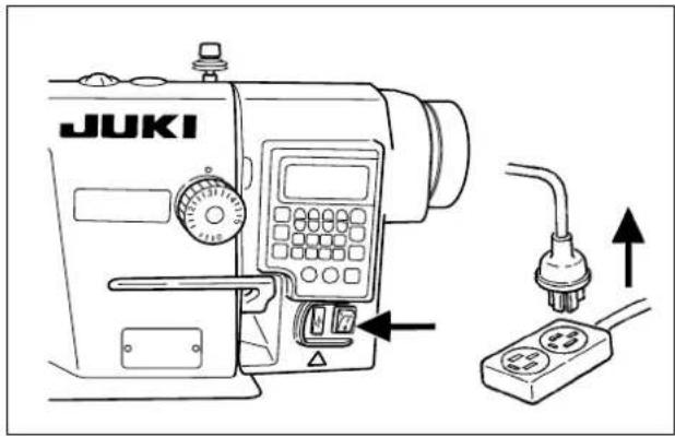
JUKI- Press the OFF button of the power switch to turn OFF the power after confirming that the sewing machine has stopped.
- Check to make sure that the power switch is in the OFF state. Then, unplug the power cord. Perform the work of step 3. after confirming that the power has been cut and it has passed for 5 minutes or more.
text_image
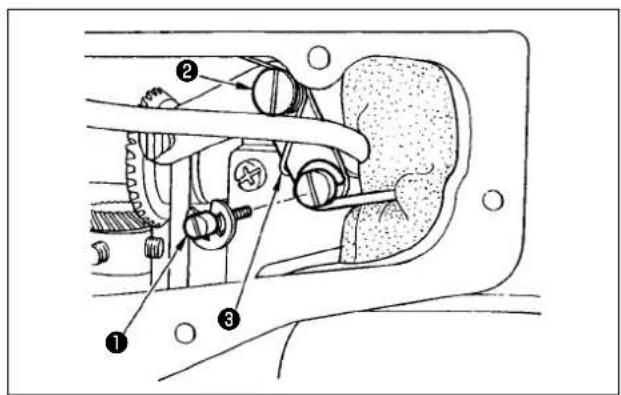
Technical diagram of a mechanical assembly with numbered components labeled ①, ②, and ③- Remove the side plate.
Replace the hinge screw of the knee lifter horizontal bar and the hinge screw of the knee lifter link with horizontal bar pin ① and hinge screw ② supplied with the unit. Install knee lifter link spring ③ as illustrated in the figure.
text_image
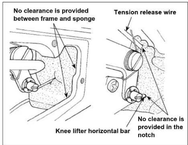
No clearance is provided between frame and sponge Tension release wire Knee lifter horizontal bar No clearance is provided in the notch- Make sure that a sponge is placed as illustrated in the figure. If not, pass the tension release wire in the upper notch and pass the knee lifter horizontal bar in the lower notch so that no clearance is provided in the notches. In addition, make sure that there is no clearance between the frame and the sponge.
* Improperly-installed sponge can be a cause of oil leakage from the bobbin winder.
text_image
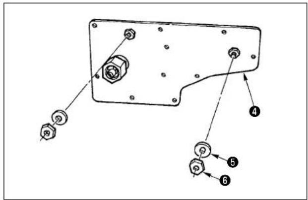
Technical diagram of a mechanical component with numbered parts labeled 4, 5, and 6 pointing to different features.- Remove washer ⑤ and nut ⑥ from side plate (asm.) ④ of the device.

text_image
Technical diagram of a mechanical assembly with numbered components labeled 1, 4, and 7- Install side plate (asm.) ④ on the sewing machine. At this time, install side plate (asm.) so that the slot in solenoid link ⑦ fits over knee lifter horizontal bar pin ①.

text_image
Technical diagram of an electrical switchgear with numbered components and labeled parts- Install solenoid (asm.) ⑧ with washer ⑤ and nut ⑥.
text_image
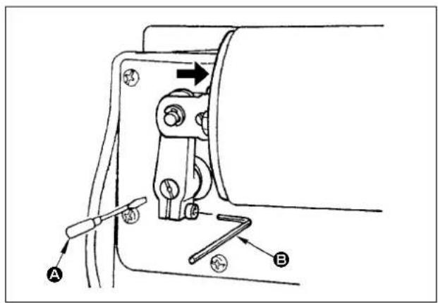
Technical diagram of a mechanical clamp or bracket with labeled parts A and B, showing tool path and directional arrows.- Lower the presser foot until it comes in close contact with the throat plate. Turn solenoid shaft counterclockwise with a screwdriver A with the solenoid pressed in the direction of the arrow, then tighten the connecting stud clamping screw with hexagonal wrench key B. (Caution) The adequate tightening torque is 3.4 to 5.9 N·m. Be aware, if the connecting stud clamping screw is excessively tightened, the solenoid arm can break.
natural_image
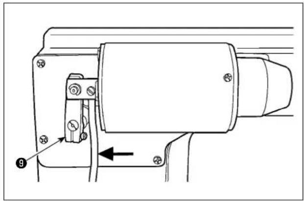
Technical line drawing of a mechanical assembly with no visible text or symbols- Pass the solenoid cord inside solenoid shaft ⑨.

text_image
Connector connection diagram Auto-lifter Solenoid & LED/TB unit For upgrading Pedal- Connect the solenoid connector to connector Ⓐ for the AK solenoid on the back surface of the control box.

natural_image
Line drawing of a car seatbelt mechanism with no text or symbolsAlmost aligned
text_image
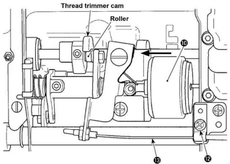
Thread trimmer cam Roller 10 13 12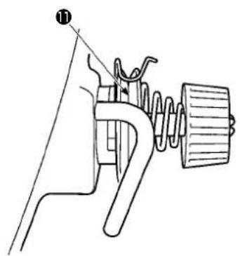
text_image
Technical diagram of a mechanical device with labeled component ①- Adjustment of the floating amount of the tension disc No. 2.
A. How to check the floating amount of the tension disc No. 2
-
Turn the main shaft until the bottom end face of needle eyelet is almost aligned with the top surface of throat plate.
-
Press thread trimmer solenoid plunger 10 to the left.
-
Check to make sure that the roller does not come in contact with the thread trimmer cam.
-
Check to make sure that the floating amount of the tension disc No. 2 is in the range of 0.5 mm to 1 mm.
B. How to adjust the floating amount of the tension disc No. 2
-
To increase the floating amount, loosen screw ⑫, and move tension release wire ⑬ to the right.
-
To decrease the floating amount, loosen screw 12, and move tension release wire 13 to the left. After adjustment, securely tighten screw 12.
(Caution) 1. To perform re-turning ON of the power, be sure to perform after the time of one second or more has passed. (If ON / OFF operation of the power is performed quickly, setting may be not changed over well.)
-
Auto-lifter is not actuated unless this function is properly selected.
-
When "FL ON" is selected without installing the auto-lifter device, starting is momentarily delayed at the start of sewing. In addition, be sure to select "FL OFF" when the auto-lifter is not installed since the touch-back switch may not work.
SPECIFICATIONS
○ Presser foot lifting amount : Standard 9mm.
○ Max. presser foot pressure : 88N.
* Line voltage : At 100%